CN110722749A - Mould for making shell, shell and manufacturing method thereof, and electronic device - Google Patents
Mould for making shell, shell and manufacturing method thereof, and electronic deviceDownload PDFInfo
- Publication number
- CN110722749A CN110722749ACN201910956440.7ACN201910956440ACN110722749ACN 110722749 ACN110722749 ACN 110722749ACN 201910956440 ACN201910956440 ACN 201910956440ACN 110722749 ACN110722749 ACN 110722749A
- Authority
- CN
- China
- Prior art keywords
- mold
- texture
- shell
- electromagnetic induction
- casing
- Prior art date
- Legal status (The legal status is an assumption and is not a legal conclusion. Google has not performed a legal analysis and makes no representation as to the accuracy of the status listed.)
- Pending
Links
Images


Classifications
- B—PERFORMING OPERATIONS; TRANSPORTING
- B29—WORKING OF PLASTICS; WORKING OF SUBSTANCES IN A PLASTIC STATE IN GENERAL
- B29C—SHAPING OR JOINING OF PLASTICS; SHAPING OF MATERIAL IN A PLASTIC STATE, NOT OTHERWISE PROVIDED FOR; AFTER-TREATMENT OF THE SHAPED PRODUCTS, e.g. REPAIRING
- B29C45/00—Injection moulding, i.e. forcing the required volume of moulding material through a nozzle into a closed mould; Apparatus therefor
- B29C45/17—Component parts, details or accessories; Auxiliary operations
- B29C45/26—Moulds
- B29C45/37—Mould cavity walls, i.e. the inner surface forming the mould cavity, e.g. linings
- B29C45/372—Mould cavity walls, i.e. the inner surface forming the mould cavity, e.g. linings provided with means for marking or patterning, e.g. numbering articles
- B—PERFORMING OPERATIONS; TRANSPORTING
- B29—WORKING OF PLASTICS; WORKING OF SUBSTANCES IN A PLASTIC STATE IN GENERAL
- B29C—SHAPING OR JOINING OF PLASTICS; SHAPING OF MATERIAL IN A PLASTIC STATE, NOT OTHERWISE PROVIDED FOR; AFTER-TREATMENT OF THE SHAPED PRODUCTS, e.g. REPAIRING
- B29C45/00—Injection moulding, i.e. forcing the required volume of moulding material through a nozzle into a closed mould; Apparatus therefor
- B29C45/0053—Injection moulding, i.e. forcing the required volume of moulding material through a nozzle into a closed mould; Apparatus therefor combined with a final operation, e.g. shaping
- B—PERFORMING OPERATIONS; TRANSPORTING
- B29—WORKING OF PLASTICS; WORKING OF SUBSTANCES IN A PLASTIC STATE IN GENERAL
- B29C—SHAPING OR JOINING OF PLASTICS; SHAPING OF MATERIAL IN A PLASTIC STATE, NOT OTHERWISE PROVIDED FOR; AFTER-TREATMENT OF THE SHAPED PRODUCTS, e.g. REPAIRING
- B29C45/00—Injection moulding, i.e. forcing the required volume of moulding material through a nozzle into a closed mould; Apparatus therefor
- B29C45/17—Component parts, details or accessories; Auxiliary operations
- B29C45/72—Heating or cooling
- B29C45/73—Heating or cooling of the mould
- B—PERFORMING OPERATIONS; TRANSPORTING
- B29—WORKING OF PLASTICS; WORKING OF SUBSTANCES IN A PLASTIC STATE IN GENERAL
- B29C—SHAPING OR JOINING OF PLASTICS; SHAPING OF MATERIAL IN A PLASTIC STATE, NOT OTHERWISE PROVIDED FOR; AFTER-TREATMENT OF THE SHAPED PRODUCTS, e.g. REPAIRING
- B29C45/00—Injection moulding, i.e. forcing the required volume of moulding material through a nozzle into a closed mould; Apparatus therefor
- B29C45/0053—Injection moulding, i.e. forcing the required volume of moulding material through a nozzle into a closed mould; Apparatus therefor combined with a final operation, e.g. shaping
- B29C2045/0079—Injection moulding, i.e. forcing the required volume of moulding material through a nozzle into a closed mould; Apparatus therefor combined with a final operation, e.g. shaping applying a coating or covering
- B—PERFORMING OPERATIONS; TRANSPORTING
- B29—WORKING OF PLASTICS; WORKING OF SUBSTANCES IN A PLASTIC STATE IN GENERAL
- B29L—INDEXING SCHEME ASSOCIATED WITH SUBCLASS B29C, RELATING TO PARTICULAR ARTICLES
- B29L2031/00—Other particular articles
- B29L2031/34—Electrical apparatus, e.g. sparking plugs or parts thereof
- B29L2031/3431—Telephones, Earphones
- B29L2031/3437—Cellular phones
Landscapes
- Engineering & Computer Science (AREA)
- Manufacturing & Machinery (AREA)
- Mechanical Engineering (AREA)
- Moulds For Moulding Plastics Or The Like (AREA)
- Injection Moulding Of Plastics Or The Like (AREA)
Abstract
Description
Translated fromChinese技术领域technical field
本申请涉及电子设备制造领域,具体地,涉及用于制作壳体的模具、壳体及其制作方法、电子设备。The present application relates to the field of electronic equipment manufacturing, and in particular, to a mold for manufacturing a casing, a casing and a manufacturing method thereof, and electronic equipment.
背景技术Background technique
随着电子设备领域制备技术的不断发展,用于电子设备的壳体材料也随之丰富。塑料具有轻巧、导热效果好、便于加工成型、成本低、不会干扰信号等优点,被广泛应用于手机、平板电脑等电子设备中,并用于制作电子设备的外壳。With the continuous development of preparation technology in the field of electronic devices, the housing materials for electronic devices are also enriched. Plastic has the advantages of light weight, good thermal conductivity, easy processing, low cost, and no signal interference.
然而,目前的用于制作塑料壳体的模具、壳体及其制作方法、电子设备,仍有待改进。However, the current molds for making plastic shells, shells, and manufacturing methods thereof, and electronic devices still need to be improved.
发明内容SUMMARY OF THE INVENTION
本申请是基于发明人对以下事实和问题的发现和认识作出的:This application is made based on the inventor's findings and knowledge of the following facts and problems:
发明人发现,目前制作塑料壳体的方法存在工艺复杂、生产成本较高等问题。目前常用的制作塑料壳体的方法包括:首先通过注射压缩成型工艺或板材高压成型工艺等形成塑料壳体基体,然后在塑料壳体基体的表面形成LOGO、纹理、颜色等外观效果,最终制得具有较好外观效果的塑料壳体。其中,壳体的纹理效果通常利用UV转印的工序来实现,UV转印工序中使用的光刻胶(PR)母模是一种耗材,价格昂贵,且使用次数有限,因而显著增加了塑料壳体的生产成本。如果利用表面具有纹理的模具制作塑料壳体,则通过注塑可以一次成型表面具有纹理的壳体,将能省去通过UV转印等制作纹理层的工艺,将能在很大程度上节省塑料壳体的生产成本。但是,发明人通过深入研究以及大量实验发现,目前利用表面具有纹理的模具制作塑料壳体时,存在纹理转印率较差、纹理效果较差的问题,即模具表面的纹理不能较好地转印到塑料壳体中,塑料壳体所能实现的纹理效果较差。因此,如果能提出一种新的用于制作塑料壳体的模具,利用该模具制作塑料壳体时,通过注塑可以一次成型表面具有纹理的壳体,并且该模具的纹理转印率较高,制作的塑料壳体的纹理效果良好,将能在很大程度上解决上述问题。The inventor found that the current method for manufacturing the plastic shell has problems such as complicated process and high production cost. At present, the commonly used methods for making plastic shells include: firstly forming a plastic shell base through an injection compression molding process or a plate high-pressure molding process, and then forming LOGO, texture, color and other appearance effects on the surface of the plastic shell base, and finally making Plastic shell with better appearance. Among them, the texture effect of the shell is usually realized by the UV transfer process. The photoresist (PR) master mold used in the UV transfer process is a consumable material, which is expensive and has a limited number of uses, thus significantly increasing the number of plastic The production cost of the housing. If a plastic shell with a textured surface is used to make a plastic shell, the shell with a textured surface can be molded at one time by injection molding, which will save the process of making a textured layer through UV transfer printing, which will save the plastic shell to a great extent. body production costs. However, through in-depth research and a large number of experiments, the inventor found that when using a mold with a textured surface to make a plastic shell, there are problems of poor texture transfer rate and poor texture effect, that is, the texture on the surface of the mold cannot be transferred well. Printed into a plastic case, the texture that can be achieved with a plastic case is less effective. Therefore, if a new mold for making plastic shells can be proposed, when using the mold to make plastic shells, a shell with texture on the surface can be molded at one time by injection molding, and the texture transfer rate of the mold is high, The texture effect of the produced plastic shell is good, which will solve the above problems to a great extent.
本申请旨在至少在一定程度上解决相关技术中的技术问题之一。The present application aims to solve one of the technical problems in the related art at least to a certain extent.
在本申请的一个方面,本申请提出了一种用于制作壳体的模具。该用于制作壳体的模具包括:第一模具;以及第二模具,所述第一模具以及所述第二模具之间限定出注塑空间,其中,所述第一模具以及所述第二模具的至少之一在朝向所述注塑空间一侧的表面具有第一纹理;以及电磁感应加热装置,所述电磁感应加热装置设置在所述第一模具以及所述第二模具的至少之一中,所述电磁感应加热装置用于对所述第一模具以及所述第二模具的至少之一进行电磁感应加热。由此,利用该模具制作壳体时,通过注塑可以形成表面具有和第一纹理相对应的纹理的壳体,该模具的纹理转印率高,制作的壳体纹理效果良好,并能节省壳体的制作工艺,节约生产成本。In one aspect of the present application, the present application proposes a mold for making a shell. The mold for making a shell includes: a first mold; and a second mold, an injection space is defined between the first mold and the second mold, wherein the first mold and the second mold At least one of them has a first texture on the surface facing the injection space side; and an electromagnetic induction heating device, the electromagnetic induction heating device is arranged in at least one of the first mold and the second mold, The electromagnetic induction heating device is used for electromagnetic induction heating at least one of the first mold and the second mold. Therefore, when using the mold to make the shell, the shell with the texture corresponding to the first texture on the surface can be formed by injection molding, the texture transfer rate of the mold is high, the shell texture effect is good, and the shell can be saved. The production process of the body can save the production cost.
在本申请的另一方面,本申请提出了一种利用前面所述的模具制作壳体的方法。该方法包括:利用所述模具进行注塑成型处理,以便形成壳体基体,所述壳体基体的表面具有和所述第一纹理相对应的第二纹理;对所述壳体基体进行后处理,以便形成所述壳体。由此,该方法可以简便地形成具有良好的纹理效果的壳体,节省了专门制作纹理层的工序,节约了生产成本,并且制备的壳体外观效果良好。In another aspect of the present application, the present application proposes a method for manufacturing a casing using the aforementioned mold. The method includes: performing an injection molding process by using the mold, so as to form a shell base body, the surface of the shell base body has a second texture corresponding to the first texture; and post-processing the shell base body, in order to form the casing. Therefore, the method can easily form a shell with a good texture effect, saves the process of specially fabricating the texture layer, saves the production cost, and the prepared shell has a good appearance effect.
在本申请的又一方面,本申请提出了一种壳体。所述壳体是由前面所述的方法形成的。由此,该壳体具有前面所述的方法所制作的壳体所具有的全部特征以及优点,在此不再赘述。总的来说,该壳体外观效果良好,且生产工艺简单,生产成本较低。In yet another aspect of the present application, the present application provides a housing. The housing is formed by the method previously described. Therefore, the casing has all the features and advantages of the casing manufactured by the method described above, and will not be repeated here. In general, the shell has good appearance effect, simple production process and low production cost.
在本申请的又一方面,本申请提出了一种壳体。该壳体包括:壳体基体,所述壳体基体是利用前面所述的模具通过注塑成型处理形成的,所述壳体基体的表面具有和所述第一纹理相对应的第二纹理;颜色层,所述颜色层设置在所述壳体基体具有所述第二纹理的一侧;镀膜层,所述镀膜层设置在所述颜色层远离所述壳体基体的一侧。。由此,该壳体具有良好的外观效果,并且该壳体的制备工艺简单,无需专门通过UV转印等形成纹理层,节省了生产工艺,节约了生产成本。In yet another aspect of the present application, the present application provides a housing. The shell includes: a shell base, which is formed by injection molding using the aforementioned mold, and the surface of the shell base has a second texture corresponding to the first texture; a color layer, the color layer is arranged on the side of the casing base with the second texture; and the coating layer is arranged on the side of the color layer away from the casing base. . Therefore, the casing has a good appearance effect, and the preparation process of the casing is simple, and there is no need to specially form a texture layer through UV transfer printing, etc., which saves the production process and saves the production cost.
在本申请的又一方面,本申请提出了一种电子设备。该电子设备包括:前面所述的方法制作的壳体或前面所述的壳体,所述壳体限定出容纳空间;主板以及存储器,所述主板以及存储器位于所述容纳空间内部;以及屏幕,所述屏幕设置在所述容纳空间中,且与所述主板相连。由此,该电子设备具有前面所述的壳体或前面所述的方法所制作的壳体所具有的全部特征以及优点,在此不再赘述。总的来说,该电子设备外观效果良好,且生产成本较低。In yet another aspect of the present application, the present application provides an electronic device. The electronic device comprises: a housing manufactured by the aforementioned method or the aforementioned housing, the housing defining an accommodating space; a mainboard and a memory, the mainboard and the memory being located inside the accommodating space; and a screen, The screen is arranged in the accommodating space and connected with the main board. Therefore, the electronic device has all the features and advantages of the aforementioned casing or the casing manufactured by the aforementioned method, which will not be repeated here. In general, the electronic device has good appearance and low production cost.
附图说明Description of drawings
图1显示了根据本申请一个示例的模具的结构示意图;FIG. 1 shows a schematic structural diagram of a mold according to an example of the present application;
图2显示了根据本申请一个示例的模具的部分结构放大示意图;FIG. 2 shows an enlarged schematic diagram of a part of the structure of a mold according to an example of the present application;
图3显示了根据本申请另一个示例的模具的结构示意图;FIG. 3 shows a schematic structural diagram of a mold according to another example of the present application;
图4显示了根据本申请一个示例的制作壳体的方法流程示意图;FIG. 4 shows a schematic flowchart of a method for manufacturing a casing according to an example of the present application;
图5显示了根据本申请另一个示例的制作壳体的方法流程示意图;FIG. 5 shows a schematic flowchart of a method for manufacturing a casing according to another example of the present application;
图6显示了根据本申请又一个示例的制作壳体的方法流程示意图;FIG. 6 shows a schematic flowchart of a method for manufacturing a casing according to yet another example of the present application;
图7显示了根据本申请一个示例的壳体基体的结构示意图;FIG. 7 shows a schematic structural diagram of a housing base according to an example of the present application;
图8显示了根据本申请一个示例的壳体的部分结构示意图;FIG. 8 shows a partial structural schematic diagram of a housing according to an example of the present application;
图9显示了根据本申请另一个示例的壳体的部分结构示意图;以及FIG. 9 shows a partial structural schematic diagram of a housing according to another example of the present application; and
图10显示了根据本申请一个示例的电子设备的结构示意图。FIG. 10 shows a schematic structural diagram of an electronic device according to an example of the present application.
附图标记说明:Description of reference numbers:
100:模具;110:第一模具;111:第一纹理;120:第二模具;130:注塑空间;140:电磁感应加热装置;150:冷却装置;200:壳体;210:壳体基体;211:第二纹理;220:颜色层;230:镀膜层;240:盖底层;250:硬化层;1000:电子设备。100: mold; 110: first mold; 111: first texture; 120: second mold; 130: injection space; 140: electromagnetic induction heating device; 150: cooling device; 200: shell; 210: shell base; 211: second texture; 220: color layer; 230: coating layer; 240: cover bottom layer; 250: hardened layer; 1000: electronic device.
具体实施方式Detailed ways
下面详细描述本申请的示例,所述示例的示例在附图中示出。下面通过参考附图描述的示例是示例性的,旨在用于解释本申请,而不能理解为对本申请的限制。Examples of the present application are described in detail below, examples of which are illustrated in the accompanying drawings. The examples described below with reference to the accompanying drawings are exemplary, and are intended to explain the present application, but should not be construed as limiting the present application.
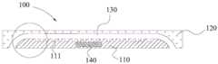
在本申请的一个方面,本申请提出了一种用于制作壳体的模具。根据本申请的一些示例,参考图1,该模具100包括:第一模具110、第二模具120以及电磁感应加热装置140,第一模具110以及第二模具120之间限定出注塑空间130,其中,第一模具110以及第二模具110的至少之一在朝向注塑空间130一侧的表面具有第一纹理(例如参考图1中所示出的,第一模具110在朝向注塑空间130一侧的表面具有第一纹理111),电磁感应加热装置140设置在第一模具110以及第二模具120的至少之一中,电磁感应加热装置140用于对第一模具110以及第二模具120的至少之一进行电磁感应加热。由此,利用该模具100制作壳体时,通过注塑可以形成表面具有和第一纹理111相对应的纹理的壳体,该模具100的纹理转印率较高,该模具100制作的壳体纹理效果良好,并能节省壳体的制作工艺,节约生产成本。需要说明的是,“转印率”即该模具表面的第一纹理转移至注塑形成的塑料壳体上时,塑料壳体上的纹理和该第一纹理的相似程度。In one aspect of the present application, the present application proposes a mold for making a shell. According to some examples of the present application, referring to FIG. 1 , the
为了方便理解,下面对该模具能获得上述有益效果的原理作简单说明:In order to facilitate understanding, the principle that the mold can obtain the above-mentioned beneficial effects is briefly explained below:
如前所述,目前制作塑料壳体的方法中,在壳体中形成纹理效果时,通常采用UV转印的方法实现,该方法采用的光刻胶母模价格昂贵,极大地增加了塑料壳体的生产成本。而根据本申请实施例的用于制作壳体的模具,通过在模具的内表面(即模具的靠近注塑空间的表面)形成第一纹理,后续通过注塑形成壳体时,可以一次注塑成型表面具有纹理的壳体,从而可以省去专门通过UV转印等方法在壳体中形成纹理效果的步骤,节省了壳体的生产工艺和生产成本;并且,根据本申请实施例的模具,通过电磁感应加热装置对模具进行加热,该电磁感应加热装置的加热温度范围宽,加热速度快,并且塑胶粒子注射完成后,可以停止给电磁感应加热装置通电,即可较为迅速地给模具降温,从而有利于模具表面的第一纹理较好地转印到塑料壳体中第一纹理的转印率较高,塑料壳体的纹理效果较好,且后续可以在该壳体的具有纹理的一侧依次形成颜色层、镀膜层等,即可获得外观效果良好的塑料壳体。As mentioned above, in the current method of making plastic shells, when the texture effect is formed in the shell, it is usually realized by the method of UV transfer printing. The photoresist master mold used in this method is expensive, which greatly increases the plastic shell. body production costs. However, according to the mold for making the shell according to the embodiment of the present application, by forming the first texture on the inner surface of the mold (that is, the surface of the mold close to the injection space), when the shell is subsequently formed by injection molding, the surface can have the first texture in one injection molding. The textured shell can save the step of forming a texture effect in the shell through methods such as UV transfer printing, which saves the production process and production cost of the shell; and, according to the mold of the embodiment of the present application, through electromagnetic induction The heating device heats the mold. The electromagnetic induction heating device has a wide heating temperature range and a fast heating speed. After the injection of the plastic particles is completed, the electromagnetic induction heating device can be stopped to energize the mold, and the mold can be cooled relatively quickly, which is beneficial to The first texture on the surface of the mold is better transferred to the plastic shell. Color layer, coating layer, etc., can obtain a plastic shell with good appearance effect.
此外,发明人发现,目前的一些利用模具制作塑料壳体的方法,存在生产周期较长(例如注塑过程中对模具进行加热以及冷却的时间较长),生产效率较低等问题,并且,塑料熔体的流动性较差,制作的壳体厚度较厚(例如厚度在1.1mm左右),不利于壳体以及电子设备的轻薄化设计,并且难以制作对尺寸和精度要求较高的壳体。而根据本申请实施例的用于制作塑料壳体的模具中,该电磁感应加热装置140可以对第一模具110以及第二模具120的至少之一进行电磁感应加热,该电磁感应加热装置140的加热速度较快,即该电磁感应加热装置可以对塑料熔体进行快速加热,从而可以增加塑料熔体的流动性和流长比(例如,塑料熔体的流长比相对于常用的电热棒加热以及蒸汽加热可以增加近50%),进而该模具100可以对粘度较大的工程树脂等进行注塑成型,应用范围广,并且可以制作结构较为精细的壳体,制备的壳体的厚度可以较小(例如可以制作厚度为0.3mm-1mm的壳体),且制作的壳体质量较好,减少了如熔迹线、缩痕、流线及灼痕等缺陷,因而制作的壳体表面光泽度较高;并且,该电磁感应加热装置140可以加热的最高温度较高,因而在注射成型之前对第一模具110以及第二模具120进行加热的温度不再受限,塑料熔体注入注塑空间130后,可以迅速进行高温塑型,从而大大缩短了塑料熔体的成型周期(跟采用热水系统等电磁感应加热装置的模具相比,塑料熔体的塑型时间可降低33%),进而提高了生产效率,节约了能源,节约了生产成本。并且,如前所述,塑胶粒子注射完成后,可以停止给电磁感应加热装置通电,进而可以较为迅速地给模具降温,从而进一步缩短了壳体的生产周期,且形成的壳体外观效果较好,表面光泽度较高,表面无纤维特征。In addition, the inventor found that some of the current methods for making plastic shells by using molds have problems such as long production cycle (for example, long heating and cooling time for the mold during the injection molding process) and low production efficiency, and the plastic The fluidity of the melt is poor, and the thickness of the produced shell is relatively thick (for example, the thickness is about 1.1 mm), which is not conducive to the thin and light design of the shell and electronic equipment, and it is difficult to make a shell with high requirements on size and accuracy. In the mold for manufacturing a plastic casing according to the embodiment of the present application, the electromagnetic
根据本申请的一些示例,参考图1,形成第一模具110以及第二模具120的材料不受特别限制,例如可以为金属材料;具体的,第一模具110以及第二模具120的具体形状等不受特别限制,本领域技术人员可以根据需要制作的壳体等的形状进行设计,例如,第一模具110和第二模具120之间的注塑空间130(即后续通过注塑形成的壳体的形状)可以是平板形的,也可以是具有一定弯曲弧度的,例如可以是2D、2.5D或3D形状的,并且注塑空间130可以是等厚的,也可以是不等厚的,例如注塑空间130的边缘可以较厚,从而可以提高形成的壳体边缘的强度,提高壳体的使用性能。According to some examples of the present application, referring to FIG. 1 , the materials for forming the
根据本申请的实施例,第一模具110以及第二模具120的至少之一在朝向注塑空间130一侧的表面具有第一纹理,例如参考图1中所示出的,第一模具110在朝向注塑空间130一侧的表面具有第一纹理111。也即是说,第一纹理可以设置在第一模具110以及第二模具的一个上,也可以同时设置在两个上,本领域技术人员可以根据所要实现的壳体的外观效果进行设计。具体的,参考图1,第一纹理111可以设置在形成的壳体用于电子设备中时,朝向电子设备内部一侧的表面,由此,后续可以在该壳体具有纹理的一侧依次形成LOGO、颜色层、镀膜层等外观等,进一步提高所制备的壳体的外观效果和使用性能。According to an embodiment of the present application, at least one of the
根据本申请的一些示例,第一纹理111可以是利用飞秒激光对第一模具110以及第二模具120的至少之一的朝向注塑空间130一侧的表面进行微蚀刻加工形成的。具体的,参考图1,可以利用飞秒激光对第一模具110的朝向注塑空间130一侧的表面进行微蚀刻加工,例如可以在圆偏振激光的诱导下,对金属材料形成的第一模具110的表面进行微刻蚀加工,以便形成第一纹理111。由此,通过飞秒激光的微刻蚀加工,可以在第一模具110的表面形成精细的纹理图案,例如可以形成纳米级的波纹结构,还可以形成多色纹理,3D立体纹理等结构,丰富了制作的壳体的纹理效果;通过对激光参数进行选择,可以简便地控制形成的第一纹理111的形状以及深度等;并且,飞秒激光的加工速度快,激光和第一模具110的作用时间短,不会对未被激光照射的第一模具110造成损伤,并且加工过程中不会产生碎屑,并能获得较大的深径比,进一步提高了所制备的第一纹理111的外观效果。According to some examples of the present application, the
根据本申请的一些示例,飞秒激光的中心波长可以为600-1000nm,飞秒激光的脉宽可以为100-150s,飞秒激光的脉冲重复频率可以为0.4-1.4kHz,飞秒激光的光斑直径可以为18-24μm,飞秒激光的能量密度可以为0.1-0.18J/cm2。由此,飞秒激光的参数在上述范围时,可以较好地在第一模具110的表面形成精细的第一纹理。具体的,飞秒激光对第一模具110进行扫描的扫描速度可以为10-20mm/s,扫描间距可为0.01-0.03mm。由此,可以在第一模具110的表面形成规则和方向统一的条纹结构,并且,如前所述,形成的第一纹理111的间距可以为5-15μm,深度可以为200-500nm,进一步提高了所制备的壳体的纹理效果以及外观效果。According to some examples of the present application, the center wavelength of the femtosecond laser may be 600-1000 nm, the pulse width of the femtosecond laser may be 100-150 s, the pulse repetition frequency of the femtosecond laser may be 0.4-1.4 kHz, and the spot of the femtosecond laser may be The diameter may be 18-24 μm, and the energy density of the femtosecond laser may be 0.1-0.18 J/cm2 . Therefore, when the parameters of the femtosecond laser are within the above range, a fine first texture can be preferably formed on the surface of the
根据本申请的实施例,第一纹理111的具体种类和排布方式不受特别限制,例如第一纹理111可以是条纹形的,也可以是圆点形的,也可以具有较复杂的图案等;第一纹理111的各条纹之间可以是等间距的,也可以是不等间距的;第一纹理111各个位置处的深度可以相同,也可以不相同。具体的,参考图1以及图2(图2为图1中圆圈部分的放大图),第一纹理111的间距d可以为5-15μm,例如可以为6μm,可以为7μm,可以为8μm,可以为9μm,可以为10μm,可以为12μm,可以为14μm等,第一纹理的深度L可以为200-500nm,例如可以为250nm,可以为300μm,可以为350μm,可以为400μm,可以为450μm等。由此,该第一纹理111的间距以及深度在上述范围中时,后续通过注塑可以在壳体的表面形成外观效果良好的纹理。According to the embodiments of the present application, the specific type and arrangement of the
根据本申请的一些示例,参考图3,模具100可以进一步包括冷却装置150,冷却装置150设置在第一模具110以及第二模具120的至少之一中,冷却装置150可对第一模具110以及第二模具120的至少之一进行快速冷却。如前所述,根据本申请实施例的模具中不仅缩短了壳体的生产周期,并且可以提高第一模具110表面的第一纹理111的转印率(即将第一纹理转印在壳体表面的转印率,转印率不小于95%,例如可达97%),甚至可以将第一模具110表面的第一纹理111完全转印复制到壳体中,且形成的壳体外观效果较好,表面光泽度较高,表面无纤维特征。According to some examples of the present application, referring to FIG. 3 , the
根据本申请的一些示例,电磁感应加热装置140的具体类型不受特别限制,只要能对第一模具110以及第二模具120进行电磁感应加热即可,例如电磁感应加热装置140可以进一步包括加热管道以及电磁感应线圈,电磁感应线圈设置在加热管道中,由此,可以简便地对第一模具110以及第二模具120进行电磁感应加热,提高了加热速率和加热温度。具体的,加热管道设置在第一模具110以及第二模具120的至少之一中,加热管道的形状等可以根据第一模具110以及第二模具120的形状等进行设计。更具体地,形成电磁感应线圈的材料可以包括玻璃纤维包裹的铜丝,由此,通过铜丝产生磁场,带磁性的第一模具110以及第二模具120可以通过磁感应直接对第一模具110以及第二模具120朝向注塑空间130一侧的表面进行加热,加热效率高,加热温度高,并且由于是非热传导加热,可以节省能源,例如相比于常规的热传导加热,可以节省40%以上的能源。According to some examples of the present application, the specific type of the electromagnetic
具体的,冷却装置150的具体类型不受特别限制,例如可以为冷却管路,冷却管路可以在塑料熔体注射完成之后,对第一模具110以及第二模具120进行快速冷却降温。需要说明的是,现有的采用热传导加热的模具中,当需要冷却降温时,加热装置(例如热水管)的温度仍然较高,无法迅速停止加热,并且采用水循环系统进行冷却时,冷却管中的水温无法迅速地降低,因此,现有的模具中的冷却装置冷却较为缓慢。而本申请中,如前所述,本申请的模具100中,采用电磁感应加热,当注塑完成需要冷却时,停止给电磁感应加热装置140通电,即可迅速地停止给模具加热,然后在冷却管路中通入冷水,可以更加迅速地度对第一模具110以及第二模具120进行快速冷却降温,从而进一步缩短了壳体的生产周期,且形成的壳体外观效果较好,表面光泽度较高,表面无纤维特征。Specifically, the specific type of the
具体的,电磁感应加热装置140的加热效率可以为20-25℃/s,例如可以为21℃/s,可以为22℃/s,可以为23℃/s,可以为24℃/s等,由此,该电磁感应加热装置140的加热效率较高,可以缩短利用该模具100制作壳体的生产周期,可以提高利用该模具100制作壳体的效率,并能提高所制作的壳体的精细度和壳体质量;具体的,电磁感应加热装置140的加热温度可为30-1000℃,例如可以为100℃,可以为200℃,可以为300℃,可以为400℃,可以为500℃,可以为600℃,可以为700℃,可以为800℃,可以为900℃等。由此,该电磁感应加热装置140的加热温度较高,可以进一步缩短利用该模具100制作壳体的时间,并能提高所制作的壳体的精细度和壳体质量。Specifically, the heating efficiency of the electromagnetic
综上可知,利用该模具制作壳体时,通过注塑可以形成表面具有和第一纹理相对应的纹理的壳体,该模具制作的壳体外观效果良好,可以省去利用UV转印等方法制作纹理层的工序,节约了生产工艺和生产成本;并且,利用该模具制作壳体时,模具中的电磁感应加热装置可以对模具进行电磁感应加热,加热速度快,加热温度高,模具中的冷却装置可以对注射后的模具进行急速冷却,进而可以缩短塑料壳体的生产周期,提高生产效率,节约能源,进一步节约生产成本,并且并能提高所制作的壳体的精细度和壳体质量。To sum up, when using this mold to make a shell, a shell with a texture corresponding to the first texture on the surface can be formed by injection molding. The process of the texture layer saves the production process and production cost; and when the mold is used to make the shell, the electromagnetic induction heating device in the mold can perform electromagnetic induction heating on the mold, the heating speed is fast, the heating temperature is high, and the cooling in the mold is reduced. The device can rapidly cool the injected mold, thereby shortening the production cycle of the plastic shell, improving production efficiency, saving energy, further saving production costs, and improving the fineness and quality of the fabricated shell.
在本申请的另一方面,本申请提出了一种制作壳体的方法。该方法利用前面所述的模具制作壳体基体,由此,该方法具有利用前面所述的模具制作壳体时所具有的全部特征以及优点,在此不再赘述。该方法通过一次注塑处理可以简便地形成具有第二纹理的壳体,节省了专门制作纹理层的工序,并且生产周期短,生产效率高,节约了生产成本,并且制备的壳体纹理效果以及外观效果良好。In another aspect of the present application, the present application provides a method of manufacturing a casing. The method utilizes the aforementioned mold to manufacture the shell base, and thus, this method has all the features and advantages of using the aforementioned mold to manufacture the shell, and will not be repeated here. The method can easily form a shell with a second texture through one injection molding process, saves the process of specially fabricating the texture layer, has short production cycle, high production efficiency, saves production cost, and has the texture effect and appearance of the prepared shell. Works well.
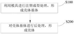
根据本申请的一些示例,参考图4,该方法包括:According to some examples of the present application, with reference to Figure 4, the method includes:
S100:利用模具进行注塑成型处理,形成壳体基体S100: Use a mold for injection molding to form a shell base
在该步骤中,利用前面所述的模具进行注塑成型处理,形成壳体基体。根据本申请的一些示例,该步骤中形成的壳体基体的表面具有和模具中的第一纹理相对应的第二纹理。具体的,如前所述,壳体基体表面的第二纹理的形状等可以和模具中的第一纹理相对应,例如壳体基体表面的第二纹理的间距可以为5-15μm,第二纹理的高度可以为200-500nm等。由此,该壳体基体表面的第二纹理的外观效果较好,且节省了专门制作纹理层的工艺。需要说明的是,该第二纹理的“高度”和前面所述的第一纹理的“深度”是相对应的,表示第二纹理相对于壳体表面的凸出程度或凹陷程度。In this step, an injection molding process is performed using the aforementioned mold to form the housing base. According to some examples of the present application, the surface of the shell base formed in this step has a second texture corresponding to the first texture in the mold. Specifically, as mentioned above, the shape and the like of the second texture on the surface of the shell base may correspond to the first texture in the mold. The height can be 200-500nm and so on. Therefore, the appearance effect of the second texture on the surface of the shell base body is better, and the process of specially fabricating the texture layer is saved. It should be noted that the "height" of the second texture corresponds to the "depth" of the first texture described above, and represents the degree of protrusion or depression of the second texture relative to the surface of the casing.
根据本申请的一些示例,参考图5,该方法进一步包括:According to some examples of the present application, with reference to FIG. 5, the method further includes:
S110:将塑料注入模具的注塑空间内,并开启电磁感应加热装置S110: Inject the plastic into the injection space of the mold, and turn on the electromagnetic induction heating device
在该步骤中,将塑料注入前面所述的模具的注塑空间内,并开启电磁感应加热装置。具体的,塑料的具体种类不受特别限制,例如,塑料可以包括:聚碳酸酯、聚甲基丙烯酸甲酯、聚对苯二甲酸乙二醇酯、聚酰胺、聚丙烯、烯丙基磺酸钠聚合物、聚苯乙烯的至少之一。上述材料形成的壳体基体强度以及透明度较好,提高了最终制备的壳体的使用性能。具体的,如前所述,注塑空间的具体形状不受特别限制,即形成的壳体基体的形状不受特别限制,例如壳体基体可以具有3D结构等。具体的,电磁感应加热装置可以和前面描述的相同,例如电磁感应加热装置的加热效率可以为20-25℃/s,电磁感应加热装置的加热温度可为30-1000℃等。如前所述,电磁感应加热装置可以对第一模具以及第二模具的至少之一进行电磁感应加热,由此,该电磁感应加热装置的加热速度快,加热温度高,且加热温度精确可控,可以缩短利用该模具制作壳体基体的时间,提高生产效率,并能提高所制作的壳体基体的精细度和壳体质量。In this step, plastic is injected into the injection space of the aforementioned mold, and the electromagnetic induction heating device is turned on. Specifically, the specific type of plastic is not particularly limited, for example, the plastic may include: polycarbonate, polymethyl methacrylate, polyethylene terephthalate, polyamide, polypropylene, allyl sulfonic acid At least one of sodium polymer and polystyrene. The shell matrix formed by the above materials has better strength and transparency, which improves the service performance of the finally prepared shell. Specifically, as mentioned above, the specific shape of the injection molding space is not particularly limited, that is, the shape of the formed shell base is not particularly limited, for example, the shell base may have a 3D structure or the like. Specifically, the electromagnetic induction heating device can be the same as described above. For example, the heating efficiency of the electromagnetic induction heating device can be 20-25°C/s, and the heating temperature of the electromagnetic induction heating device can be 30-1000°C. As mentioned above, the electromagnetic induction heating device can perform electromagnetic induction heating on at least one of the first mold and the second mold, thus, the electromagnetic induction heating device has fast heating speed, high heating temperature, and accurate and controllable heating temperature , the time for making the shell base body by using the mold can be shortened, the production efficiency can be improved, and the fineness and the shell quality of the made shell base body can be improved.
需要说明的是,为了进一步缩短利用该模具制作壳体基体的时间,该方法可以进一步包括:将塑料注入模具的注塑空间内之前,预先开启电磁感应加热装置,即可以在上一批产品取出之后,立即对第一模具以及第二模具进行加热。由此,在注射塑料熔体之前,预先对第一模具以及第二模具进行电磁感应加热,可以进一步缩短塑料熔体的高温塑型时间,缩短壳体基体的生产周期,提高生产效率。It should be noted that, in order to further shorten the time for using the mold to make the shell base, the method may further include: before injecting the plastic into the injection space of the mold, turning on the electromagnetic induction heating device in advance, that is, after the last batch of products is taken out , the first mold and the second mold are heated immediately. Therefore, before injecting the plastic melt, electromagnetic induction heating is performed on the first mold and the second mold in advance, which can further shorten the high-temperature molding time of the plastic melt, shorten the production cycle of the shell matrix, and improve the production efficiency.
S120:开启冷却装置S120: Turn on the cooling device
在该步骤中,在前面步骤中将塑料注射成型之后,可以开启冷却装置,冷却装置可以对第一模具以及第二模具进行快速冷却。根据本申请的一些示例,冷却装置可以和前面描述的相同,具体的,冷却装置可以包括冷却管路。由此,可以进一步缩短利用该模具制作壳体基体的时间,并能提高所制作的壳体基体的精细度和壳体质量。In this step, after the plastic is injection-molded in the previous step, the cooling device can be turned on, and the cooling device can rapidly cool the first mold and the second mold. According to some examples of the present application, the cooling device may be the same as that described above, and specifically, the cooling device may include a cooling pipeline. Therefore, the time for manufacturing the housing base body by using the mold can be further shortened, and the fineness and the quality of the manufactured housing base body can be improved.
如前所述,该制作壳体的方法中,利用模具中的电磁感应加热装置和冷却装置,对第一模具和第二模具进行快速加热和快速冷却,不仅能提高壳体基体的生产效率,并且,可以提高将第一模具表面的第一纹理转印到壳体基体上形成第二纹理的转印率,具体的,第一纹理转印至壳体基体表面形成第二纹理的转印率可以不小于95%,例如可以为97%等,由此,该方法中将第一纹理转印至壳体基体表面形成第二纹理的转印率较高,可以较为完整和清晰地将第一模具表面的纹理图案等转印到壳体基体中,在壳体基体中形成精细的纹理图案,进一步提高了所制作的壳体的外观效果。并且,该方法制作的壳体基体表面的光泽度较高,具体的,壳体基体表面的光泽度相对于常规的例如通过热传导加热制作的壳体基体,可提高90%及以上,例如,利用常规方法制作的壳体基体表面的光泽度为53GU时,利用本申请中的方法制作的壳体基体的表面光泽度可以为102GU等,由此,该方法制作的壳体基体,不仅表面的纹理效果良好,而且表面光泽度较高,进一步提高了所制备的壳体的外观效果。As mentioned above, in the method for making the shell, the electromagnetic induction heating device and the cooling device in the mold are used to rapidly heat and cool the first mold and the second mold, which can not only improve the production efficiency of the shell matrix, but also In addition, the transfer rate of transferring the first texture on the surface of the first mold to the housing base to form the second texture can be increased, specifically, the transfer rate of transferring the first texture to the surface of the housing base to form the second texture It may not be less than 95%, for example, it may be 97%, etc. Therefore, in this method, the transfer rate of transferring the first texture to the surface of the shell base to form the second texture is relatively high, and the first texture can be more completely and clearly The texture patterns and the like on the surface of the mold are transferred into the shell base body, and fine texture patterns are formed in the shell base body, which further improves the appearance effect of the manufactured shell body. In addition, the surface gloss of the shell base produced by this method is relatively high. Specifically, the gloss of the shell base surface can be increased by 90% or more compared with the conventional shell base made by heat conduction heating, for example, by using When the gloss of the surface of the shell base made by the conventional method is 53GU, the surface gloss of the shell base made by the method in the present application can be 102GU, etc. Therefore, the shell base made by this method, not only the surface texture The effect is good, and the surface gloss is high, which further improves the appearance effect of the prepared shell.
并且,如前所述,该制作壳体的方法中,利用模具中的电磁感应加热装置和冷却装置,对第一模具和第二模具进行快速加热和快速冷却,还可以避免形成的壳体基体表面产生浮纤问题,提高形成的壳体基体的表面光泽度。由此,进一步提高了所制作的壳体的外观效果。Moreover, as mentioned above, in the method for making the shell, the electromagnetic induction heating device and the cooling device in the mold are used to rapidly heat and cool the first mold and the second mold, and the shell matrix formed can also be avoided. The problem of floating fibers occurs on the surface, which improves the surface gloss of the formed shell matrix. Thereby, the appearance effect of the manufactured casing is further improved.
S200:对壳体基体进行后处理,形成壳体S200: post-processing the shell base to form a shell
在该步骤中,对前面步骤中形成的具有第二纹理的壳体基体进行后处理,以便形成壳体。具体的,该后处理即在壳体基体的具有第二纹理的一侧形成LOGO、颜色层、镀膜层、盖底层等外观层,以便形成外观效果良好的壳体。如前所述,该方法中,通过一次注塑可以形成具有第二纹理的壳体基体,因此,在该后处理步骤中,可以省去通过UV转印等形成纹理层的步骤,节约了生产工艺和生产成本,并且不影响最终制备的壳体的外观效果。In this step, the shell substrate with the second texture formed in the previous step is post-processed to form the shell. Specifically, the post-processing is to form a LOGO, a color layer, a coating layer, a cover layer and other appearance layers on the side of the casing base with the second texture, so as to form a casing with good appearance effect. As mentioned above, in this method, the shell base body with the second texture can be formed by one injection. Therefore, in this post-processing step, the step of forming the texture layer by UV transfer printing can be omitted, and the production process can be saved and production cost, and does not affect the appearance of the final prepared shell.
具体的,可以在壳体基体具有第二纹理的一侧形成LOGO,例如可以在壳体基体具有第二纹理的一侧通过丝网印刷,丝印镜面银或者镜面金等镜面油墨,然后热固化成型形成LOGO。Specifically, the LOGO can be formed on the side of the shell base with the second texture. For example, the side of the shell base with the second texture can be screen-printed, screen-printed with mirror ink such as mirror silver or mirror gold, and then thermally cured. Form a LOGO.
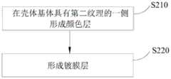
根据本申请的一些示例,参考图6,形成LOGO之后,该方法进一步包括:According to some examples of the present application, referring to FIG. 6 , after the LOGO is formed, the method further includes:
S210:在壳体基体具有第二纹理的一侧形成颜色层S210 : forming a color layer on the side of the shell base with the second texture
该步骤中,在壳体基体具有第二纹理的一侧形成颜色层。根据本申请的一些示例,颜色层的具体颜色以及种类等不受特别限制,本领域技术人员可以根据需要的壳体的外观效果进行设计。具体的,可以在壳体基体具有第二纹理的一侧印刷颜色油墨,以便形成颜色层。具体的,也可以先在壳体基体具有第二纹理的一侧蒸镀形成第一增亮膜,然后通过磁控溅射镀膜的方法,在第一增亮膜的表面形成第二增亮膜,然后在第二增亮膜的表面通过镀膜工艺形成光学颜色膜,最后再在光学颜色膜的表面通过浸染的方法形成渐变色。由此,上述方法可以形成色彩丰富、光泽度高且外观效果良好的颜色层。并且该颜色层可以和前面所述的壳体基体中的第二纹理进行叠加,形成丰富多彩的外观效果。In this step, a color layer is formed on the side of the shell base having the second texture. According to some examples of the present application, the specific color and type of the color layer are not particularly limited, and those skilled in the art can design according to the desired appearance effect of the casing. Specifically, color inks may be printed on the side of the housing base having the second texture, so as to form a color layer. Specifically, a first brightness enhancement film can also be formed by vapor deposition on the side of the casing substrate with the second texture, and then a second brightness enhancement film can be formed on the surface of the first brightness enhancement film by magnetron sputtering coating method. Then, an optical color film is formed on the surface of the second brightness enhancement film by a coating process, and finally a gradient color is formed on the surface of the optical color film by a dip dyeing method. Thus, the above method can form a color layer with rich color, high gloss and good appearance effect. And the color layer can be superimposed with the second texture in the shell base described above to form a colorful appearance effect.
S220:形成镀膜层S220: forming a coating layer
在该步骤中,在前面步骤中形成的颜色层远离壳体基体的一侧形成镀膜层。具体的,镀膜层的形成方法不受特别限制,例如可以是通过物理气相沉积法(PVD)形成的,也可以是通过真空镀膜法,例如真空不导电镀膜法(NVCM)形成的。由此,可以进一步提升制备的壳体的外观效果,并且,该镀膜层和前面所述的颜色层以及壳体基体中的第二纹理可以相互叠加,形成丰富多彩的外观效果。In this step, a coating layer is formed on the side of the color layer formed in the previous step away from the housing base. Specifically, the method for forming the coating layer is not particularly limited, for example, it can be formed by physical vapor deposition (PVD), or it can be formed by vacuum coating method, such as vacuum non-conductive coating method (NVCM). Therefore, the appearance effect of the prepared shell can be further improved, and the coating layer, the aforementioned color layer and the second texture in the shell base can be superimposed on each other to form a colorful appearance effect.
根据本申请的一些示例,为了进一步提高所制备的壳体的使用性能,该方法可以进一步包括:在镀膜层远离颜色层的一侧印刷盖底油墨,以便形成盖底层。具体的,盖底层的光透过率不大于1%。由此,该壳体用于电子设备中时,该盖底层可以遮挡电子设备内部的元件等,进一步提高该壳体的使用性能。According to some examples of the present application, in order to further improve the use performance of the prepared casing, the method may further include: printing a cover bottom ink on a side of the coating layer away from the color layer, so as to form a cover bottom layer. Specifically, the light transmittance of the cover bottom layer is not more than 1%. Therefore, when the casing is used in an electronic device, the cover bottom layer can shield the components and the like inside the electronic device, thereby further improving the use performance of the casing.
根据本申请的一些示例,为了进一步提高所制作的壳体的使用性能,在形成盖底层之后,该方法可以进一步包括:对前面步骤中形成的壳体进行热压成型处理,以便形成具有预定弧度的壳体。由此,进一步丰富了所制作的壳体的外观。According to some examples of the present application, in order to further improve the usability of the manufactured casing, after forming the cover bottom layer, the method may further include: performing a thermoforming process on the casing formed in the previous steps, so as to form a casing having a predetermined arc. 's shell. Thereby, the appearance of the manufactured casing is further enriched.
根据本申请的一些示例,为了进一步提高所制作的壳体的使用性能,在形成盖底层之后,该方法可以进一步包括在壳体基体远离颜色层的一侧形成硬化层。具体的,可以在壳体基体远离颜色层的一侧淋涂硬化层材料,并通过UV固化的方式形成硬化层。由此,硬化层可以进一步增强所制作的壳体的硬度等,提高所制作的壳体的使用性能。According to some examples of the present application, in order to further improve the use performance of the fabricated case, after forming the cover bottom layer, the method may further include forming a hardened layer on the side of the case base away from the color layer. Specifically, the hardened layer material can be spray-coated on the side of the housing base away from the color layer, and the hardened layer can be formed by UV curing. Thereby, the hardened layer can further enhance the hardness of the produced case, etc., and improve the usability of the produced case.
为了进一步提高所制作的壳体的使用性能,在形成硬化层之后,可以进一步对制作的壳体进行切割处理,例如CNC(数控加工)处理,除去多余的边角料等等,获得具有特定尺寸和形状的适合装配的壳体。In order to further improve the performance of the fabricated shell, after the hardened layer is formed, the fabricated shell can be further cut, such as CNC (Numerical Control Machining) processing, to remove excess scraps, etc., to obtain a specific size and shape. suitable housing for assembly.
综上可知,该方法利用前面所述的模具可以简便地形成具有第二纹理的壳体基体,可以省去利用UV转印等方法制作纹理层的工序,节约了生产工艺和生产成本;并且,该方法制作壳体时,模具中的电磁感应加热装置可以对模具进行电磁感应加热,加热速度快,加热温度高,模具中的冷却装置可以对注射后的模具进行急速冷却,进而可以缩短塑料壳体的生产周期,提高生产效率,节约能源,进一步节约生产成本,并能提高所制作的壳体的纹理效果、精细度和壳体质量。To sum up, the method can easily form the shell matrix with the second texture by using the aforementioned mold, and can save the process of making the texture layer by methods such as UV transfer printing, and save the production process and production cost; and, When the shell is made by the method, the electromagnetic induction heating device in the mold can perform electromagnetic induction heating on the mold, the heating speed is fast, and the heating temperature is high, and the cooling device in the mold can rapidly cool the injected mold, thereby shortening the plastic shell. The production cycle of the shell is improved, the production efficiency is improved, the energy is saved, the production cost is further saved, and the texture effect, the fineness and the shell quality of the manufactured shell can be improved.
在本申请的又一方面,本申请提出了一种壳体。根据本申请的一些示例,该壳体是由前面所述的方法形成的。由此,该壳体具有前面所述的方法所制作的壳体所具有的全部特征以及优点,在此不再赘述。总的来说,该壳体外观效果良好,且生产工艺简单,生产成本较低。In yet another aspect of the present application, the present application provides a housing. According to some examples of the present application, the housing is formed by the method described above. Therefore, the casing has all the features and advantages of the casing manufactured by the method described above, and will not be repeated here. In general, the shell has good appearance effect, simple production process and low production cost.
在本申请的又一方面,本申请提出了一种壳体。根据本申请的一些示例,该壳体包括壳体基体,该壳体基体可以是由前面所述的模具通过注塑成型处理形成的。由此,该壳体具有利用前面所述的模具制作壳体时所具有的全部特征以及优点,在此不再赘述。根据本申请的一些示例,参考图7和图8(图8为图7中的虚线框部分所对应的壳体的结构示意图),该壳体200包括壳体基体210、颜色层220以及镀膜层230,其中,壳体基体210是利用前面所述的模具通过注塑成型处理形成的,壳体基体210的表面具有和前面所述的模具的第一纹理相对应的第二纹理211,颜色层220设置在壳体基体210具有第二纹理211的一侧,镀膜层230设置在颜色层220远离壳体基体210的一侧。由此,该壳体200具有良好的纹理效果和外观效果,并且该壳体200的制备工艺简单,无需专门通过UV转印等形成纹理层,节省了生产工艺,节约了生产成本。In yet another aspect of the present application, the present application provides a housing. According to some examples of the present application, the housing includes a housing base, which may be formed by an injection molding process from the aforementioned mold. Therefore, the shell has all the features and advantages of using the aforementioned mold to make the shell, and will not be repeated here. According to some examples of the present application, referring to FIG. 7 and FIG. 8 ( FIG. 8 is a schematic structural diagram of the casing corresponding to the portion of the dashed frame in FIG. 7 ), the
根据本申请的一些示例,壳体基体210的厚度可以为0.3mm-1mm,例如可以为0.4mm,可以为0.5mm,可以为0.6mm,可以为0.7mm等,由此,该壳体基体210的厚度较小,有利于壳体的轻薄化。According to some examples of the present application, the thickness of the
根据本申请的一些示例,参考图9,壳体200可以进一步包括:盖底层240以及硬化层250,盖底层240可以设置在镀膜层230远离颜色层220的一侧,硬化层250可以设置在壳体基体210远离颜色层220的一侧。由此,进一步提高了该壳体200的使用性能。According to some examples of the present application, referring to FIG. 9 , the
在本申请的又一个方面,本申请提出了一种电子设备。根据本申请的一些示例,参考图10,该电子设备1000包括:前面所述的壳体200或前面所述的方法所制作的壳体、主板以及存储器、屏幕(图中未示出),壳体200限定出容纳空间,主板以及存储器位于容纳空间内部,屏幕设置在容纳空间中且与主板相连。由此,该电子设备1000具有前面所述的壳体200或前面所述的方法所制作的壳体组件所具有的全部特征以及优点,在此不再赘述。总的来说,该电子设备1000外观效果良好,且生产成本较低。In yet another aspect of the present application, the present application provides an electronic device. According to some examples of the present application, referring to FIG. 10 , the
示例性的,电子设备可以为移动或便携式并执行无线通信的各种类型的计算机系统设备中的任何一种。具体的,电子设备可以为移动电话或智能电话(例如,基于iPhoneTM,基于Android TM的电话),便携式游戏设备(例如Nintendo DS TM,PlayStationPortable TM,Gameboy Advance TM,iPhone TM)、膝上型电脑、PDA、便携式互联网设备、音乐播放器以及数据存储设备,其他手持设备以及诸如手表、入耳式耳机、吊坠、头戴式耳机等。Illustratively, the electronic device may be any of various types of computer system devices that are mobile or portable and that perform wireless communications. Specifically, the electronic device can be a mobile phone or a smart phone (eg, iPhoneTM-based, AndroidTM-based phones), portable gaming devices (eg, Nintendo DSTM, PlayStationPortableTM, Gameboy AdvanceTM, iPhoneTM), laptop computers, PDAs, portable internet devices, music players and data storage devices, other handheld devices and such as watches, earphones, pendants, headphones, etc.
电子设备还可以是多个电子设备中的任何一个,多个电子设备包括但不限于蜂窝电话、智能电话、其他无线通信设备、个人数字助理、音频播放器、其他媒体播放器、音乐记录器、录像机、照相机、其他媒体记录器、收音机、医疗设备、车辆运输仪器、计算器、可编程遥控器、寻呼机、膝上型计算机、台式计算机、打印机、上网本电脑、个人数字助理(PDA)、便携式多媒体播放器(PMP)、运动图像专家组(MPEG-1或MPEG-2)音频层3(MP3)播放器,便携式医疗设备以及数码相机及其组合。The electronic device may also be any of a number of electronic devices including, but not limited to, cellular phones, smart phones, other wireless communication devices, personal digital assistants, audio players, other media players, music recorders, Video recorders, cameras, other media recorders, radios, medical equipment, vehicle transportation equipment, calculators, programmable remote controls, pagers, laptops, desktop computers, printers, netbooks, personal digital assistants (PDAs), portable multimedia Players (PMP), Moving Picture Experts Group (MPEG-1 or MPEG-2) Audio Layer 3 (MP3) players, portable medical devices and digital cameras and combinations thereof.
下面通过具体的示例对本申请的方案进行说明,需要说明的是,下面的示例仅用于说明本申请,而不应视为限定本申请的范围。示例中未注明具体技术或条件的,按照本领域内的文献所描述的技术或条件或者按照产品说明书进行。The solution of the present application will be described below through specific examples. It should be noted that the following examples are only used to illustrate the present application, and should not be regarded as limiting the scope of the present application. If no specific technique or condition is specified in the example, the technique or condition described in the literature in the field or the product specification is used.
示例1Example 1
(1)制作表面具有纹理的模具。该模具包括第一模具和第二模具(参考图1中所示出的第一模具110和第二模具120),利用飞秒激光对第一模具朝向注塑空间一侧的表面进行微刻蚀加工,飞秒激光的中心波长为800nm,飞秒激光的脉宽为120s,飞秒激光的脉冲重复频率为1.0kHz,飞秒激光的光斑直径为20μm,飞秒激光的能量密度为0.15J/cm2,飞秒激光对第一模具进行扫描的扫描速度为15mm/s,扫描间距为0.02mm。经过飞秒激光微刻蚀之后,在第一模具的表面形成规则和方向统一的第一纹理,形成的第一纹理的间距为10μm,深度为350nm。(1) Make a mold with a textured surface. The mold includes a first mold and a second mold (refer to the
(2)利用步骤(1)中制作的模具进行注塑成型。采用的塑料为聚碳酸酯,将塑料熔体注入模具的注塑空间中,利用电磁感应加热装置对模具进行电磁感应加热,电磁感应加热装置包括设置在模具中的加热管道以及设置在加热管道中的玻纤包裹的铜丝,并利用冷却水管对注射后的模具进行快速冷却。模具的加热温度设定为140-170℃,模具的冷却温度设定为60-90℃,螺杆均段化温度设定为260-300℃,电磁感应加热装置的加热速率为23℃/s。制得表面具有第二纹理壳体基体A。(2) Injection molding is performed using the mold produced in step (1). The plastic used is polycarbonate, the plastic melt is injected into the injection molding space of the mold, and the mold is electromagnetically heated by an electromagnetic induction heating device. The electromagnetic induction heating device includes a heating pipe arranged in the mold and a heating pipe arranged in the heating pipe. The copper wire wrapped with glass fiber and the cooling water pipe are used to quickly cool the injected mold. The heating temperature of the mold is set to 140-170°C, the cooling temperature of the mold is set to 60-90°C, the homogenization temperature of the screw is set to 260-300°C, and the heating rate of the electromagnetic induction heating device is 23°C/s. A shell substrate A with a second textured surface was produced.
对比例1Comparative Example 1
其他操作同示例1,不同的是,该对比例1中的加热装置为常规的热传导加热,即蒸汽加热。制得表面具有第二纹理壳体基体B。Other operations are the same as in Example 1, except that the heating device in this Comparative Example 1 is conventional heat conduction heating, that is, steam heating. The resulting surface has a second textured shell base B.
性能测试Performance Testing
(1)分别利用示例1和对比例1中的模具制作壳体基体,经测试,示例1中的模具制作壳体基体A的时间比对比例1中减少了33%,且示例1中制作壳体的能源消耗比对比例1降低了40%。(1) The molds in Example 1 and Comparative Example 1 were used to make the shell base, respectively. After testing, the time for making the shell base A with the mold in Example 1 was reduced by 33% compared with that in Comparative Example 1, and the shell in Example 1 was produced. The energy consumption of the body is 40% lower than that of the comparative example 1.
(2)对示例1和对比例1形成的壳体基体进行表面光泽度测试,测得示例1中的壳体表面的光泽度为79GU,对比例1中的壳体表面的光泽度为23GU。因此,示例1中的壳体表面的光泽度显著高于对比例1。(2) Surface glossiness test was carried out on the shell substrates formed in Example 1 and Comparative Example 1. The measured glossiness of the shell surface in Example 1 was 79GU, and the glossiness of the shell surface in Comparative Example 1 was 23GU. Therefore, the glossiness of the case surface in Example 1 was significantly higher than that in Comparative Example 1.
(3)对示例1和对比例1中的壳体基体上的纹理转印率进行测试,测得示例1中的纹理的转印率为97%,对比例1中的纹理转印率为50%。(3) The texture transfer rate on the shell substrates in Example 1 and Comparative Example 1 was tested, and it was measured that the texture transfer rate in Example 1 was 97%, and the texture transfer rate in Comparative Example 1 was 50%. %.
测试结果表面,本申请中的模具中,采用电磁感应加热以及急速冷却,可以缩短塑料壳体的生产周期,提高生产效率,节约能源,进一步节约生产成本,并且并能提高所制作的壳体的表面光泽度和纹理转印率。The test results show that the use of electromagnetic induction heating and rapid cooling in the mold in this application can shorten the production cycle of the plastic shell, improve production efficiency, save energy, further save production costs, and improve the quality of the shell. Surface gloss and texture transfer rate.
以上详细描述了本申请的实施方式,但是,本申请并不限于上述实施方式中的具体细节,在本申请的技术构思范围内,可以对本申请的技术方案进行多种简单变型,这些简单变型均属于本申请的保护范围。另外需要说明的是,在上述具体实施方式中所描述的各个具体技术特征,在不矛盾的情况下,可以通过任何合适的方式进行组合。The embodiments of the present application have been described in detail above. However, the present application is not limited to the specific details in the above-mentioned embodiments. Within the scope of the technical concept of the present application, various simple modifications can be made to the technical solutions of the present application. It belongs to the protection scope of this application. In addition, it should be noted that each specific technical feature described in the above-mentioned specific implementation manner may be combined in any suitable manner under the circumstance that there is no contradiction.
在本说明书的描述中,参考术语“示例”、“一些示例”等的描述意指结合该示例或示例描述的具体特征、结构、材料或者特点包含于本申请的至少一个示例或示例中。在本说明书中,对上述术语的示意性表述不必须针对的是相同的示例或示例。而且,描述的具体特征、结构、材料或者特点可以在任一个或多个示例或示例中以合适的方式结合。此外,在不相互矛盾的情况下,本领域的技术人员可以将本说明书中描述的不同示例或示例以及不同示例或示例的特征进行结合和组合。In the description of this specification, reference to a description of the terms "example," "some examples," etc. means that a particular feature, structure, material, or characteristic described in connection with the example or example is included in at least one example or instance of the present application. In this specification, schematic representations of the above terms are not necessarily directed to the same example or instance. Furthermore, the particular features, structures, materials or characteristics described may be combined in any suitable manner in any one or more examples or examples. Furthermore, those skilled in the art may combine and combine the different examples or examples and features of the different examples or examples described in this specification without conflicting each other.
此外,术语“第一”、“第二”仅用于描述目的,而不能理解为指示或暗示相对重要性或者隐含指明所指示的技术特征的数量。由此,限定有“第一”、“第二”的特征可以明示或者隐含地包括一个或者更多个该特征。In addition, the terms "first" and "second" are only used for descriptive purposes, and should not be construed as indicating or implying relative importance or implying the number of indicated technical features. Thus, a feature defined as "first" or "second" may expressly or implicitly include one or more of that feature.
尽管上面已经示出和描述了本申请的示例,可以理解的是,上述示例是示例性的,不能理解为对本申请的限制,本领域的普通技术人员在本申请的范围内可以对上述示例进行变化、修改、替换和变型。Although the examples of the present application have been shown and described above, it should be understood that the above-mentioned examples are exemplary and should not be construed as limitations of the present application, and those of ordinary skill in the art can perform the above-mentioned examples within the scope of the present application. Variations, modifications, substitutions and variations.
Claims (17)
Translated fromChinesePriority Applications (1)
| Application Number | Priority Date | Filing Date | Title |
|---|---|---|---|
| CN201910956440.7ACN110722749A (en) | 2019-10-10 | 2019-10-10 | Mould for making shell, shell and manufacturing method thereof, and electronic device |
Applications Claiming Priority (1)
| Application Number | Priority Date | Filing Date | Title |
|---|---|---|---|
| CN201910956440.7ACN110722749A (en) | 2019-10-10 | 2019-10-10 | Mould for making shell, shell and manufacturing method thereof, and electronic device |
Publications (1)
| Publication Number | Publication Date |
|---|---|
| CN110722749Atrue CN110722749A (en) | 2020-01-24 |
Family
ID=69220895
Family Applications (1)
| Application Number | Title | Priority Date | Filing Date |
|---|---|---|---|
| CN201910956440.7APendingCN110722749A (en) | 2019-10-10 | 2019-10-10 | Mould for making shell, shell and manufacturing method thereof, and electronic device |
Country Status (1)
| Country | Link |
|---|---|
| CN (1) | CN110722749A (en) |
Cited By (3)
| Publication number | Priority date | Publication date | Assignee | Title |
|---|---|---|---|---|
| CN113115529A (en)* | 2021-04-07 | 2021-07-13 | 维沃移动通信有限公司 | Machining method of shell, shell and electronic equipment |
| CN113246379A (en)* | 2021-04-25 | 2021-08-13 | 广州安通林灯具有限公司 | Double-color injection molding process and application thereof in field of automobile lamp preparation |
| CN113878827A (en)* | 2020-07-01 | 2022-01-04 | Oppo广东移动通信有限公司 | Injection mold, injection molding machine and injection molding method |
Citations (6)
| Publication number | Priority date | Publication date | Assignee | Title |
|---|---|---|---|---|
| CN101277594A (en)* | 2007-03-30 | 2008-10-01 | 深圳富泰宏精密工业有限公司 | Electronic apparatus housing and method for manufacturing the same |
| KR100870857B1 (en)* | 2007-08-28 | 2008-11-27 | (주)쉘-라인 | Electronic device case and manufacturing method |
| CN102725117A (en)* | 2009-12-17 | 2012-10-10 | 三菱重工塑胶科技股份有限公司 | Molding method and manufacturing method of molded product |
| CN204123628U (en)* | 2014-09-18 | 2015-01-28 | 宏利科技(苏州)有限公司 | Adopt the mould of electromagnetic induction heating |
| CN104441408A (en)* | 2013-09-13 | 2015-03-25 | 联想(北京)有限公司 | Shell preparation method and electronic equipment |
| CN108215055A (en)* | 2016-12-21 | 2018-06-29 | 比亚迪股份有限公司 | A kind of shell and preparation method thereof and electronic product |
- 2019
- 2019-10-10CNCN201910956440.7Apatent/CN110722749A/enactivePending
Patent Citations (6)
| Publication number | Priority date | Publication date | Assignee | Title |
|---|---|---|---|---|
| CN101277594A (en)* | 2007-03-30 | 2008-10-01 | 深圳富泰宏精密工业有限公司 | Electronic apparatus housing and method for manufacturing the same |
| KR100870857B1 (en)* | 2007-08-28 | 2008-11-27 | (주)쉘-라인 | Electronic device case and manufacturing method |
| CN102725117A (en)* | 2009-12-17 | 2012-10-10 | 三菱重工塑胶科技股份有限公司 | Molding method and manufacturing method of molded product |
| CN104441408A (en)* | 2013-09-13 | 2015-03-25 | 联想(北京)有限公司 | Shell preparation method and electronic equipment |
| CN204123628U (en)* | 2014-09-18 | 2015-01-28 | 宏利科技(苏州)有限公司 | Adopt the mould of electromagnetic induction heating |
| CN108215055A (en)* | 2016-12-21 | 2018-06-29 | 比亚迪股份有限公司 | A kind of shell and preparation method thereof and electronic product |
Non-Patent Citations (1)
| Title |
|---|
| 吴舜英,徐敬一: "《泡沫塑料成型》", 31 March 1992, 北京:化学工业出版社* |
Cited By (3)
| Publication number | Priority date | Publication date | Assignee | Title |
|---|---|---|---|---|
| CN113878827A (en)* | 2020-07-01 | 2022-01-04 | Oppo广东移动通信有限公司 | Injection mold, injection molding machine and injection molding method |
| CN113115529A (en)* | 2021-04-07 | 2021-07-13 | 维沃移动通信有限公司 | Machining method of shell, shell and electronic equipment |
| CN113246379A (en)* | 2021-04-25 | 2021-08-13 | 广州安通林灯具有限公司 | Double-color injection molding process and application thereof in field of automobile lamp preparation |
Similar Documents
| Publication | Publication Date | Title |
|---|---|---|
| CN110722749A (en) | Mould for making shell, shell and manufacturing method thereof, and electronic device | |
| Chen et al. | Dynamic mold surface temperature control using induction heating and its effects on the surface appearance of weld line | |
| CN103780724B (en) | A kind of plastic shell with metal wire-drawing outward appearance and preparation method thereof | |
| CN203282709U (en) | Fused depositional 3D printer with local heating device | |
| JP7403011B2 (en) | Induction heating molding for parts with thermoplastic parts | |
| CN102672880B (en) | Carbon fiber member manufacturing method and carbon fiber member manufactured by method | |
| US20100007045A1 (en) | Method for manufacturing shell with textured appearance | |
| CN102480865B (en) | A kind of electronic product casing and manufacture method thereof | |
| CN111295062A (en) | Housing assembly and preparation method thereof, and electronic device | |
| CN101439582A (en) | Method for manufacturing light guide plate | |
| KR20140000549A (en) | Apparatus and method for manufacturing housing | |
| CN102416688A (en) | Treatment process of in-mold injection product | |
| CN106494111A (en) | Seamless cylindrical metallic working version and its processing technology | |
| CN101664996A (en) | Flat plate bending device for plastic blanks and flat plate bending process for plastic blanks | |
| CN112477493A (en) | Shell, preparation method thereof and mobile terminal | |
| CN110877461A (en) | A molding method for a mobile terminal high-bright texture battery cover | |
| Nian et al. | Multilayer injection molding of high‐profile convex lens | |
| WO2022028072A1 (en) | Housing structure, preparation method therefor, and electronic device | |
| CN105428780B (en) | A kind of workpiece production method, workpiece and electronic equipment | |
| CN101712193B (en) | In-mold decoration method | |
| CN101340787A (en) | In-mold decoration injection molding shell and manufacturing method thereof | |
| CN107009571B (en) | A kind of plastic surface treatment method, plastic surface and combined shell | |
| JP2016155337A (en) | Lamination molding apparatus and lamination molding method | |
| CN104118088A (en) | Plastic product and molding method thereof | |
| WO2019001261A1 (en) | Optical film, mold and electronic device cover plate |
Legal Events
| Date | Code | Title | Description |
|---|---|---|---|
| PB01 | Publication | ||
| PB01 | Publication | ||
| SE01 | Entry into force of request for substantive examination | ||
| SE01 | Entry into force of request for substantive examination | ||
| RJ01 | Rejection of invention patent application after publication | Application publication date:20200124 | |
| RJ01 | Rejection of invention patent application after publication |