CN110720897A - Optical pulse wave image measuring instrument and pulse condition measuring method - Google Patents
Optical pulse wave image measuring instrument and pulse condition measuring methodDownload PDFInfo
- Publication number
- CN110720897A CN110720897ACN201811048854.1ACN201811048854ACN110720897ACN 110720897 ACN110720897 ACN 110720897ACN 201811048854 ACN201811048854 ACN 201811048854ACN 110720897 ACN110720897 ACN 110720897A
- Authority
- CN
- China
- Prior art keywords
- module
- measuring instrument
- light source
- pulse wave
- optical pulse
- Prior art date
- Legal status (The legal status is an assumption and is not a legal conclusion. Google has not performed a legal analysis and makes no representation as to the accuracy of the status listed.)
- Pending
Links
- 230000003287optical effectEffects0.000titleclaimsabstractdescription51
- 238000000034methodMethods0.000titleclaimsabstractdescription28
- 238000003384imaging methodMethods0.000claimsabstractdescription84
- 210000000707wristAnatomy0.000claimsabstractdescription49
- 238000009532heart rate measurementMethods0.000claimsabstractdescription13
- 210000004204blood vesselAnatomy0.000claimsdescription18
- 238000005259measurementMethods0.000claimsdescription12
- 238000001228spectrumMethods0.000claimsdescription8
- 230000001360synchronised effectEffects0.000claimsdescription7
- 230000000004hemodynamic effectEffects0.000claimsdescription3
- 230000007246mechanismEffects0.000claimsdescription3
- 238000012545processingMethods0.000claimsdescription3
- 230000002093peripheral effectEffects0.000claims2
- 230000000007visual effectEffects0.000claims1
- 230000005540biological transmissionEffects0.000description11
- 238000003745diagnosisMethods0.000description11
- 238000004364calculation methodMethods0.000description10
- 238000010586diagramMethods0.000description10
- 238000001514detection methodMethods0.000description8
- 238000004891communicationMethods0.000description6
- 238000002559palpationMethods0.000description6
- 230000008859changeEffects0.000description5
- 210000002321radial arteryAnatomy0.000description5
- 238000000691measurement methodMethods0.000description4
- 238000003825pressingMethods0.000description4
- 238000004458analytical methodMethods0.000description3
- 230000008569processEffects0.000description3
- 230000010349pulsationEffects0.000description3
- 238000005070samplingMethods0.000description3
- 239000003814drugSubstances0.000description2
- 238000007667floatingMethods0.000description2
- 239000000463materialSubstances0.000description2
- NJPPVKZQTLUDBO-UHFFFAOYSA-NnovaluronChemical compoundC1=C(Cl)C(OC(F)(F)C(OC(F)(F)F)F)=CC=C1NC(=O)NC(=O)C1=C(F)C=CC=C1FNJPPVKZQTLUDBO-UHFFFAOYSA-N0.000description2
- 230000035485pulse pressureEffects0.000description2
- 238000005452bendingMethods0.000description1
- 230000000903blocking effectEffects0.000description1
- 230000000295complement effectEffects0.000description1
- 238000006073displacement reactionMethods0.000description1
- 238000005516engineering processMethods0.000description1
- 238000005286illuminationMethods0.000description1
- 238000012986modificationMethods0.000description1
- 230000004048modificationEffects0.000description1
- 238000012634optical imagingMethods0.000description1
- 230000000149penetrating effectEffects0.000description1
- 210000005259peripheral bloodAnatomy0.000description1
- 239000011886peripheral bloodSubstances0.000description1
- 230000000284resting effectEffects0.000description1
- 239000004065semiconductorSubstances0.000description1
- 230000035807sensationEffects0.000description1
- 230000002792vascularEffects0.000description1
Images


Classifications
- A—HUMAN NECESSITIES
- A61—MEDICAL OR VETERINARY SCIENCE; HYGIENE
- A61B—DIAGNOSIS; SURGERY; IDENTIFICATION
- A61B5/00—Measuring for diagnostic purposes; Identification of persons
- A61B5/02—Detecting, measuring or recording for evaluating the cardiovascular system, e.g. pulse, heart rate, blood pressure or blood flow
- A—HUMAN NECESSITIES
- A61—MEDICAL OR VETERINARY SCIENCE; HYGIENE
- A61B—DIAGNOSIS; SURGERY; IDENTIFICATION
- A61B5/00—Measuring for diagnostic purposes; Identification of persons
- A61B5/0059—Measuring for diagnostic purposes; Identification of persons using light, e.g. diagnosis by transillumination, diascopy, fluorescence
Landscapes
- Health & Medical Sciences (AREA)
- Life Sciences & Earth Sciences (AREA)
- Biomedical Technology (AREA)
- Heart & Thoracic Surgery (AREA)
- Veterinary Medicine (AREA)
- Biophysics (AREA)
- Pathology (AREA)
- Engineering & Computer Science (AREA)
- Public Health (AREA)
- Physics & Mathematics (AREA)
- Medical Informatics (AREA)
- Molecular Biology (AREA)
- Surgery (AREA)
- Animal Behavior & Ethology (AREA)
- General Health & Medical Sciences (AREA)
- Cardiology (AREA)
- Physiology (AREA)
- Measuring Pulse, Heart Rate, Blood Pressure Or Blood Flow (AREA)
Abstract
Translated fromChinese
Description
Translated fromChinese技术领域technical field
本发明是关于一种脉象量测仪,特别是关于一种利用光学成像系统进行量测并对脉波影像进行分析的光学脉波影像量测仪。The present invention relates to a pulse condition measuring instrument, in particular to an optical pulse wave image measuring instrument that utilizes an optical imaging system to measure and analyze pulse wave images.
背景技术Background technique
在传统把脉时,中医师透过触、摸、压等动作按压患者手腕的桡动脉来感觉患者双手手腕的寸、关、尺三部位的浮、中、沉三个按压深度的脉象,并施以不同的按压力度来感测不同的脉象变化。然而,脉诊的准确度会因不同中医师的触诊位置、触诊习惯以及按压力度的不同而有所差异,并无法客观地描述脉象,如此一来将使脉象变化的结果具有较大的变异性,更容易对患者发出错误的诊断结果。In the traditional pulse measurement, the TCM practitioner presses the radial artery of the patient's wrist by touching, touching, pressing, etc., to feel the pulse of the patient's wrist and wrist at the three pressing depths of floating, middle and sinking, and apply Sensing different pulse changes with different pressing force. However, the accuracy of pulse diagnosis will vary depending on the palpation position, palpation habits and pressing force of different TCM physicians, and it is impossible to objectively describe the pulse condition, so the results of pulse condition changes will have a greater impact. Variability, making it easier to issue erroneous diagnoses to patients.
为了解决上述问题,相关技术人员提出一种触感结合把脉辅助装置,其通过中医师于手指上配戴一包含感测单元的把脉辅助装置,以即时侦测中医师于把脉时施予患者手腕的压力大小,以利于在把脉的过程中调整按压力道,并可将所得的脉象信息数字化,进而提供患者一客观的脉象诊断结果。然而,前述的触感结合把脉辅助装置在把脉的过程中仍须由中医师判断触诊位置并对患者手腕的施加压力,并无法对触诊位置及按压力度进行标准化,致使不同中医师对同一患者所发出的脉诊结果仍有差异。In order to solve the above-mentioned problems, a related artisan proposes an auxiliary device for tactile sensation combined with pulse detection, which can instantly detect the pulse pulse applied by the Chinese medicine practitioner to the patient's wrist during pulse detection by wearing a pulse detection auxiliary device including a sensing unit on the finger of the Chinese medicine practitioner. The pressure can be adjusted so as to adjust the pressure channel during the pulse detection process, and the obtained pulse information can be digitized, thereby providing the patient with an objective pulse diagnosis result. However, in the above-mentioned tactile-combined pulse sensing auxiliary device, the TCM physician still needs to determine the palpation position and apply pressure to the patient's wrist during the pulse sensing process. There are still differences in the pulse diagnosis results issued.
为了解决上述问题,相关技术人员更提出利用气囊等加压装置对患者的桡动脉加压,并撷取加压后所反应的脉压信号进行分析的脉诊检测仪,以获得标准化的脉诊结果。然而,前述的脉诊检测仪虽可避免不同中医师的触诊习惯所导致的结果误差,但仍须以外力对患者手腕施加压力并进行接触式诊断,以得到相对的脉压信号而进行后续的脉诊结果判定,不仅在操作方法上面较为繁复,亦可能因接触式的把脉方式而影响脉诊结果的准确率。In order to solve the above-mentioned problems, the relevant technical personnel further proposed a pulse diagnosis detector that uses a pressure device such as a balloon to pressurize the radial artery of a patient, and captures and analyzes the pulse pressure signal reflected after the pressurization, so as to obtain a standardized pulse diagnosis. result. However, although the aforementioned pulse diagnosis detector can avoid the result error caused by the palpation habits of different TCM physicians, it still requires external force to exert pressure on the patient's wrist and perform contact diagnosis to obtain the relative pulse pressure signal for subsequent follow-up. The judgment of the pulse diagnosis results of the 1000-degree pulse diagnosis is not only complicated in the operation method, but also may affect the accuracy of the pulse diagnosis results due to the contact-type pulse detection method.
因此,市面上亟需一种兼具使用便利性及达成客观的脉象结果诉求的脉象量测仪。Therefore, there is an urgent need in the market for a pulse condition measuring instrument that is convenient to use and achieves objective pulse condition results.
发明内容SUMMARY OF THE INVENTION
本发明的一态样在于提供一种光学脉波影像量测仪,其特征在于,包含一基座、一外罩、一成像模块、一光源模块、一结构光投影装置、一电路模块、一运算模块以及一显示模块。外罩设置于基座上,用以提供一遮光范围。光源模块设置于成像模块的一侧边。结构光投影装置设置于外罩内。成像模块设置于外罩内,且成像模块用以撷取一待测区域的一影像。光源模块设置于成像模块的一侧边。电路模块电性连接成像模块与光源模块。运算模块信号连接电路模块。显示模块信号连接运算模块。An aspect of the present invention is to provide an optical pulse wave image measuring instrument, which is characterized by comprising a base, a cover, an imaging module, a light source module, a structured light projection device, a circuit module, and an operation module and a display module. The cover is arranged on the base to provide a shading range. The light source module is arranged on one side of the imaging module. The structured light projection device is arranged in the outer cover. The imaging module is disposed in the housing, and the imaging module is used for capturing an image of a region to be tested. The light source module is arranged on one side of the imaging module. The circuit module is electrically connected to the imaging module and the light source module. The operation module signal is connected to the circuit module. The display module signal is connected to the calculation module.
本发明的另一态样在于提供一种脉象量测方法,其特征在于,包含下述步骤:进行一定位调整步骤,其是透过一影像定位辅助方式以将一成像模块对准于一受测者的一手腕区域,并调整该成像模块及一结构光投影装置至一量测位置,其中手腕区域包含寸、关及尺三部位中至少一者;进行一拍摄步骤,其是利用成像模块撷取手腕区域的一影像信息;进行一运算步骤,其是利用一运算模块分析前述的影像信息,以得一运算结果;进行一比对步骤,其是利用运算模块将前述的运算结果与一脉象分类数据集合进行比对,以输出受测者的一脉象量测结果。Another aspect of the present invention is to provide a pulse condition measurement method, which is characterized by comprising the following steps: performing a positioning adjustment step, in which an imaging module is aligned with a subject through an image positioning assistance method. Measuring a wrist area of the subject, and adjusting the imaging module and a structured light projection device to a measurement position, wherein the wrist area includes at least one of three parts: inch, guan and chi; performing a photographing step, which is by using the imaging module Capture an image information of the wrist area; perform a calculation step, which is to use an calculation module to analyze the aforementioned image information to obtain a calculation result; perform a comparison step, which is to use the calculation module to compare the aforementioned calculation result with a The pulse condition classification data sets are compared to output a pulse condition measurement result of the subject.
借此,本发明的光学脉波影像量测仪与脉象量测方法利用成像模块自动撷取受测者的手腕区域影像信息,并透过运算模块进行运算与分析,以进一步将脉象信息视觉化,并可同时对脉象的量测手法及其结果等数据进行标准化,避免已知利用触诊式或压力式脉象侦测所造成的结果误差,进而提供一客观且准确的脉象量测结果。Thereby, the optical pulse wave image measuring instrument and pulse condition measuring method of the present invention use the imaging module to automatically capture the image information of the subject's wrist region, and perform operations and analysis through the operation module, so as to further visualize the pulse condition information It can also standardize the pulse measurement methods and the results and other data at the same time, so as to avoid the result error caused by the known use of palpation or pressure pulse detection, thereby providing an objective and accurate pulse measurement result.
附图说明Description of drawings
为让本发明的上述和其他目的、特征、优点与实施例能更明显易懂,所附附图的说明如下:In order to make the above and other objects, features, advantages and embodiments of the present invention more clearly understood, the accompanying drawings are described as follows:
图1是绘示本发明一实施方式的光学脉波影像量测仪的架构示意图;FIG. 1 is a schematic diagram illustrating the structure of an optical pulse wave image measuring instrument according to an embodiment of the present invention;
图2是绘示本发明一实施方式的一实施例的光学脉波影像量测仪的示意图;2 is a schematic diagram illustrating an optical pulse wave image measuring instrument according to an example of an embodiment of the present invention;
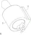
图3是绘示图2实施例的光学脉波影像量测仪的部分剖示图;FIG. 3 is a partial cross-sectional view illustrating the optical pulse wave image measuring instrument according to the embodiment of FIG. 2;
图4是绘示图3实施例的光学脉波影像量测仪的成像模块、结构光投影装置与移动模块的放大示意图;4 is an enlarged schematic diagram illustrating an imaging module, a structured light projection device and a moving module of the optical pulse wave image measuring instrument according to the embodiment of FIG. 3;
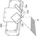
图5是绘示图4实施例的光学脉波影像量测仪的结构光投影装置与移动模块的放大示意图;5 is an enlarged schematic diagram illustrating a structured light projection device and a moving module of the optical pulse wave image measuring instrument according to the embodiment of FIG. 4;
图6是绘示图5实施例的光学脉波影像量测仪的结构光投影装置的放大示意图;FIG. 6 is an enlarged schematic view of the structured light projection device of the optical pulse wave image measuring instrument according to the embodiment of FIG. 5;
图7是绘示图2实施例的光学脉波影像量测仪的操作状态示意图;以及FIG. 7 is a schematic diagram illustrating an operation state of the optical pulse wave image measuring instrument according to the embodiment of FIG. 2; and
图8是绘示本发明另一实施方式的脉象量测方法的流程图。FIG. 8 is a flowchart illustrating a pulse condition measurement method according to another embodiment of the present invention.
【符号说明】【Symbol Description】
100:光学脉波影像量测仪100: Optical pulse wave image measuring instrument
110:基座110: Pedestal
111:承靠手腕脉枕111: Relying on the wrist pulse pillow
120:外罩120: Cover
200:成像模块200: Imaging Module
202:成像偏光片202: Imaging polarizer
204:成像镜头204: Imaging Lens
206:影像感测器206: Image Sensor
208:同步电路208: Synchronous circuit
300:光源模块300: Light source module
302:光源偏光片302: Light source polarizer
304:光源304: Light Source
308:同步电路308: Synchronous circuit
400:电路模块400: Circuit Module
402:电源电路402: Power circuit
404:控制电路404: Control circuit
406:驱动电路406: Drive circuit
408:数据传输电路408: Data transmission circuit
500:运算模块500: Operation module
600:显示模块600: Display module
700:结构光投影装置700: Structured light projection device
702:光源偏光片702: Light source polarizer
704:结构光光源704: Structured light source
708:同步电路708: Synchronization Circuit
720:数字微镜装置720: Digital Micromirror Device
730:反射镜730: Reflector
800:移动模块800: Mobile Module
900:脉象量测方法900: Pulse measurement method
910、920、930、940:步骤910, 920, 930, 940: Steps
11:手腕区域11: Wrist area
A:待测区域A: Area to be tested
P:投影条纹P: Projection fringes
R:光束R: Beam
具体实施方式Detailed ways
以下将参照附图说明本发明的多个实施例。为明确说明起见,许多实务上的细节将在以下叙述中一并说明。然而,应了解到,这些实务上的细节不应用以限制本发明。也就是说,在本发明部分实施例中,这些实务上的细节是非必要的。此外,为简化附图起见,一些已知惯用的结构与元件在附图中将以简单示意的方式绘示;并且重复的元件将可能使用相同的编号表示。Various embodiments of the present invention will be described below with reference to the accompanying drawings. For the sake of clarity, many practical details are set forth in the following description. It should be understood, however, that these practical details should not be used to limit the invention. That is, in some embodiments of the present invention, these practical details are unnecessary. Furthermore, for the purpose of simplifying the drawings, some well-known and conventional structures and elements will be shown in the drawings in simplified schematic form; and repeating elements will possibly be designated by the same reference numerals.
请参照图1、图2与图3,图1是绘示本发明一实施方式的光学脉波影像量测仪的架构示意图,图2是绘示本发明一实施方式的一实施例的光学脉波影像量测仪100的示意图,而图3则是绘示图2实施例的光学脉波影像量测仪100的部分剖示图。本发明旨在于提供一种光学脉波影像量测仪100,用以检测一受测者(图未绘示)的一待测区域A的脉象状态,其包含基座110、一外罩120、一成像模块200、一光源模块300、一结构光投影装置700、一电路模块400、一运算模块500以及一显示模块600。Please refer to FIG. 1 , FIG. 2 and FIG. 3 , FIG. 1 is a schematic diagram illustrating the structure of an optical pulse wave image measuring instrument according to an embodiment of the present invention, and FIG. 2 is an optical pulse wave image measuring instrument according to an embodiment of the present invention. FIG. 3 is a partial cross-sectional view of the optical pulse wave
基座110可包含一量测定位辅助装置(图未绘示)及一辅助手腕固定治具(图未绘示),用以辅助待测区域A放置于适当位置。较佳地,基座110可包含一承靠手腕脉枕111(标示于图3),以增加手腕的固定效率。外罩120设置于基座110上。较佳地,外罩120可用以阻隔待测区域A的所有周边环境光源。具体言之,外罩120可为一遮蔽环境干扰挡板,用以阻隔所有周边环境的干扰光,且外罩120的材质可为全波段不穿透材料,但本发明并不以此为限。The base 110 may include an auxiliary device for measuring and positioning (not shown in the figure) and an auxiliary wrist fixing jig (not shown in the figure) to assist in placing the area A to be measured in a proper position. Preferably, the
成像模块200设置于外罩120内,且成像模块200是以一方向角度撷取待测区域A的一影像。成像模块200可包含一成像偏光片202、一成像镜头204、一影像感测器206以及一同步电路208,其中成像偏光片202可包含一线偏振片,而成像镜头204则可包含多片透镜,至于透镜的数目及其设置方式并非本发明的主要特征,在此不再赘述。影像感测器206可为感光耦合元件(Charge-coupled device,CCD)或互补性氧化金属半导体(Complementarymetal-oxide-semiconductor,CMOS),且本发明并不以此为限。The
光源模块300设置于成像模块200的一侧边,且光源模块300可包含一光源304、光源偏光片302以及一同步电路308,其中光源偏光片302可包含一线偏振片,而成像模块200的成像偏光片202与光源模块300的光源偏光片302可为正交配置,但本发明并不以此为限。具体地,光源模块300可设置于成像模块200的至少一侧边或与成像模块200同轴设置。光源304可为发光二极管(Light-emitting diode,LED)闪光灯、频闪灯(Stroboscopic lamp)或Lamp光源机等照射装置。然在此须说明的是,光源模块300的数量可视实际需求而配置为二个或二个以上,二光源模块300是环绕设置于成像模块200的周边,借以对待测区域A提供较佳的亮度,且本发明并不以前述说明与附图揭露的内容为限。The
结构光投影装置700设置于外罩120内,用以提供待测区域A一结构光,且结构光投影装置700可包含一结构光光源704、光源偏光片702以及一同步电路708,其中光源偏光片702可包含一线偏振片,而成像模块200的成像偏光片202与结构光投影装置700的光源偏光片702可为正交配置,但本发明并不以此为限。具体地,结构光投影装置700是利用非接触式空间频率域影像技术(Spatial Frequency Domain Imaging,SFDI)进行结构光投影,且撷取结构光投影至待测区域A后所反射的光线,并根据待测区域A的反射光所呈现的光波信号变化计算脉动位置、脉动深度等信息,进而取得待测区域A的血管的血流动力学变化所产生的压力波形变而对血管的管径宽度及高度方向或周边组织的一应变量。较佳地,结构光投影装置700可包含数字光学处理投影机(DLP Projector)或液晶投影机(LCD Projector),而数字光学处理投影机可包含一数字微镜装置(Digital Micromirror Device)以及一数字微镜装置控制模块(图未绘示)。再者,结构光投影装置700的光源频谱可包含可见光波段(波长范围约为400nm至700nm)至近红外光波段(Near InfraRed,NIR,波长范围约为700nm至1000nm)。The structured
电路模块400可设置于基座110内并电性连接成像模块200、光源模块300与结构光投影装置700,且电路模块400可包含一电源电路402、一控制电路404、一驱动电路406以及一数据传输电路408,其中控制电路404可用以控制前述各构件中所可能包含的电路电源,而数据传输电路408则可用以将成像模块200所撷取的影像的信息传输至运算模块500。此外,数据传输电路408可包含一无线通讯传输模块(图未绘示)或一有线通讯传输模块(图未绘示),其中无线通讯传输模块可为一蓝芽无线通讯传输模块、一红外线无线通讯传输模块或无线区域网络模块,但本发明并不以此为限。The
运算模块500信号连接电路模块400,借以透过电路模块400的数据传输电路408接收成像模块200所撷取的影像信息,并透过运算模块500对前述的影像信息进行分析与运算,以输出一脉象量测结果。较佳地,运算模块500可包含一计算机处理器、一移动装置运算单元或可完成前述动作的模块,例如微控制器(Micro Controller Unit,MCU)、中央处理器(Central Processing Unit,CPU)、进阶精简指令集机器(Advanced RISC Machine,ARM)、数字信号处理器(Digital Signal Processor,DSP)或智能移动装置,但本发明并不以此为限。较佳地,运算模块500可以非接触式空间频率域影像(SFDI)解调变演算法分析待测区域A的影像的影像信息,如手腕区域的血管的血流动力学变化所产生的压力波形变而对血管的管径宽度及高度方向或周边组织的一应变量,并经由所测得的应力与应变曲线来观察压力波改变对脉象结构变化,借以获得客观且标准化的脉象量测结果。The
显示模块600信号连接运算模块500,借以接收并显示影像与脉搏量测结果等信息,且显示模块600可包含一显示器、一有线显示装置或一无线显示装置。具体而言,运算模块500可建置于一移动装置或一个人电脑中,或可整合并内建于外罩120或基座110上,且本发明并不以任一实施方式或实施例为限。The display module 600 is signal-connected to the
另外,如图1所示,光学脉波影像量测仪100可还包含一移动模块800,连接于成像模块200,且成像模块200与结构光投影装置700可透过移动模块800而同步位移。较佳地,移动模块800可包含马达、气压缸、微机电等移动源,并可包含一移动机构(图未绘示),用以带动成像模块200与结构光投影装置700于垂直方向、水平方向及倾斜方向移动,借以将成像模块200与结构光投影装置700调整至适当的拍摄位置。In addition, as shown in FIG. 1 , the optical pulse wave
请参照图2与图3,光学脉波影像量测仪100是用以检测一受测者的手腕区域11(即前述的待测区域A)处的脉象状态,且光学脉波影像量测仪100的架构大致上如图1所示,即包含一基座110、一外罩120、一成像模块200、一光源模块300、一结构光投影装置700、一电路模块400、一运算模块500以及一显示模块600。Please refer to FIG. 2 and FIG. 3 , the optical pulse wave
光学脉波影像量测仪100的基座110可为一矩形座体,而外罩120则为一设置于基座110上的一概呈半圆形的壳体,用以阻隔所有周边环境光。具体地,前述的遮光范围是位于基座110与外罩120之间,而待测区域则位于外罩120的遮光范围中,以进一步防止外界光源影响光学脉波影像量测仪100的脉象量测准确度。The
成像模块200设置于外罩120的内侧,并以一方向角度撷取手腕区域11的一影像信息,其中成像模块200的成像范围约为50mm2至100mm2。光源模块300环绕设置于成像模块200的周围并抵靠于外罩120上,而待测区域(图未标示)则位于外罩120的遮光范围中并为成像模块200、光源模块300与结构光投影装置700所环绕,以在本发明的光学脉波影像量测仪100对受测者的手腕区域11处的脉象进行量测时提供充足的光线。较佳地,在图2与图3的实施例中,光源模块300的数量可为二,二光源模块300彼此相对地环绕设置于成像模块200的周围,且二光源模块300是分别抵靠于外罩120上,以有效地维持外罩120内的空间尺寸并对其提供充足的光源,但本发明并不以此为限。The
请同时参照图4、图5与图6,图4是绘示图3实施例的光学脉波影像量测仪100的成像模块200、结构光投影装置700与移动模块800的放大示意图,图5是绘示图4实施例的光学脉波影像量测仪100的结构光投影装置700与移动模块800的放大示意图,而图6则是绘示图5实施例的光学脉波影像量测仪100的结构光投影装置700的放大示意图。Please refer to FIGS. 4 , 5 and 6 at the same time. FIG. 4 is an enlarged schematic diagram illustrating the
结构光投影装置700设置于外罩120内并邻设于成像模块200,且结构光投影装置700可包含一结构光光源704、一数字微镜装置720以及一反射镜730,且光学脉波影像量测仪100可还包含一移动模块800。详细而言,结构光光源704将会发射一光束R,而光束R将会被反射镜730反射至数字微镜装置720中,数字微镜装置720则会进一步处理光束R的光学性质而产生具有投影条纹P的结构光,再由数字微镜装置720将结构光投射至手腕区域11,并由成像模块200采集受手腕区域11所反射的光线,以利后续的分析。移动模块800则连接于成像模块200上,并进一步与结构光投影装置700连接,且成像模块200与结构光投影装置700则可透过移动模块800而同步位移。较佳地,移动模块800可包含一移动机构(图未绘示),用以带动成像模块200与结构光投影装置700于垂直方向、水平方向、倾斜方向及旋转方向移动,以将成像模块200及结构光投影装置700至一量测位置。The structured
此外,图2与图3的光学脉波影像量测仪100的其他构件如电路模块400、运算模块500以及显示模块600则已如前文所述,在此则不再赘述。In addition, other components of the optical pulse wave
以下将配合参照图7与图8,以说明本发明的光学脉波影像量测仪100进行脉象量测的方法。请参照图7与图8,图7是绘示图2实施例的光学脉波影像量测仪100的操作状态示意图,而图8则是绘示本发明另一实施方式的脉象量测方法900的流程图。脉象量测方法900包含步骤910、步骤920、步骤930以及步骤940。7 and 8 , the method for measuring pulse condition by the optical pulse wave
步骤910是进行一定位调整步骤,其是透过影像定位辅助方式以将成像模块200对准于与受测者的一手腕区域11,并调整成像模块200及结构光投影装置700至一量测位置,其中手腕区域11包含寸、关及尺(图未标示)三部位中至少一者。详细而言,当受测者欲使用本发明的光学脉波影像量测仪100进行脉象量测时,受测者将先以手心朝上的姿势置于基座110与外罩120之间的遮光范围中,并将手腕区域11放置于基座110的承靠基座脉枕111上,以将手腕区域11定位至正确的量测位置,并调整受测者的手腕区域11高度与心脏齐平,此时光学脉波影像量测仪100将于一空间频率分别调变结构光投影装置700的结构光光源704与成像模块200,以找手腕区域11的桡动脉或周边血管的延伸方向,并找出桡动脉的脉动最明显的地方,借以定位寸、关、尺三部位。Step 910 is to perform a positioning adjustment step, which is to align the
较佳地,定位调整步骤可进一步透过移动模块800带动成像模块200以及结构光投影装置700进行垂直方向、水平方向、倾斜方向及旋转方向的同步位移,以将成像模块200与结构光投影装置700移动至一个最佳的量测位置。另外,定位调整步骤可调整成像模块200与结构光投影装置700的位置,以使成像模块200的视野范围同时包含手腕区域11的寸、关、尺三部位,以对同时对寸、关、尺三部位进行脉象的量测。较佳地,前述的结构光投影装置700的光源频谱的波段范围为可见光波段(波长范围为400nm–700nm)至近红外光波段(波长范围为700nm–1000nm)。具体地,影像定位辅助方式是利用皮肤表面纹理特征与结构光调变解算高度信息侦测手腕区域11的特征,并利用一影像感测器与结构光投影装置700的光源频谱进行影像定位,以找出关部的位置,而关部沿血管延伸方向往手掌延伸约10mm的位置则为寸部,关部沿血管延伸方向往手肘延伸约10mm的位置则为尺部,其中前述的影像感测器可为RGB感测器,但本发明并不以此为限。Preferably, in the positioning adjustment step, the moving
步骤920为进行一拍摄步骤,其是利用成像模块200撷取手腕区域11的一影像信息,其中手腕区域11的影像信息包含血管的管径宽度形变数据及血管的高度方向形变数据或周边组织形变数据。详细而言,拍摄步骤是透过调变频率为0.0142mm-1至0.5mm-1的结构光光源704与成像模块200,以同步高速摄影方法撷取手腕区域11的不同量测点于不同空间频率的调变影像,其中,结构光空间频率可包含最低至频率为零(亦即,光源中不包含结构光成分)的调变影像,以及最高至成像模块200可解析的空间频率调变影像。Step 920 is to perform a photographing step, which is to use the
另外,同步高速摄影方法可包含同步更新结构光光源704与成像模块200的步骤,其中结构光光源704与成像模块200的同步更新率是满足奈奎斯特取样定理(NyquistTheorem)的取样频率,其约为120FPS(Frame per Second)至240FPS以上的取样频率,以避免脉波混迭现象发生。In addition, the synchronous high-speed photography method may include the step of synchronously updating the structured
步骤930为进行一运算步骤,其是利用运算模块500分析影像信息,以得一运算结果。详细而言,运算模块500先计算结构光的投影条纹P受手腕区域11调变的弯曲程度,再利用运算模块500以非接触式空间频率域影像解调变演算法解调变投影条纹P的弯曲程度而得到手腕区域11的相位信息,并将前述的相位信息转换为血管的管径宽度形变数据及血管的高度方向形变数据或周边组织形变数据,并分析血管的血流动力学变化所产生的压力波形变所致的血管的管径宽度及高度方向或周边组织的应变量,以获得桡动脉或周边血管位置、血管深度等信息,进而重建手腕区域11的血管分布状况及单位时间内的脉象变化情形的运算结果。Step 930 is an operation step, which uses the
步骤940为进行一比对步骤,其是利用运算模块500将前述的运算结果与一脉象分类数据集合进行比对,以输出受测者的一脉象量测结果。详细而言,脉象分类数据集合包含浮、沈、虚、实、迟、数的六大类共二十八种脉象特征,而运算模块500则会将运算结果与前述二十八种脉象特征进行比对,以提供对应的脉象量测结果。Step 940 is a comparison step, which uses the
综上所述,本发明的光学脉波影像量测仪利用成像模块自动撷取受测者的手腕区域影像信息,并透过运算模块进行运算与分析,以进一步将脉象信息视觉化,并可同时对脉象的量测手法及其结果等数据进行标准化,避免已知利用触诊式或压力式脉象侦测所造成的结果误差。再者,本发明的脉象量测方法透过将非接触式空间频率域影像技术应用于脉象量测中,且以自动化撷取脉象的影像信息与计算,并将结果与脉象分类数据集合进行比对,以辅助中医师进行把脉与诊断,进而提供一客观且准确的脉象量测结果。To sum up, the optical pulse wave image measuring instrument of the present invention uses the imaging module to automatically capture the image information of the subject's wrist region, and performs calculation and analysis through the operation module, so as to further visualize the pulse condition information, and can At the same time, the data such as pulse measurement methods and results are standardized, so as to avoid the result error caused by the known use of palpation or pressure pulse detection. Furthermore, the pulse condition measurement method of the present invention applies the non-contact spatial frequency domain imaging technology to the pulse condition measurement, and automatically captures the image information and calculation of the pulse condition, and compares the result with the pulse condition classification data set. Yes, to assist TCM physicians in pulse detection and diagnosis, thereby providing an objective and accurate pulse measurement result.
虽然本发明已以实施方式揭露如上,然其并非用以限定本发明,任何熟悉此技艺者,在不脱离本发明的精神和范围内,当可作各种的更动与润饰,因此本发明的保护范围当视所附的权利要求书所界定的范围为准。Although the present invention has been disclosed in the above embodiments, it is not intended to limit the present invention. Anyone skilled in the art can make various changes and modifications without departing from the spirit and scope of the present invention. Therefore, the present invention The scope of protection shall be subject to the scope defined by the appended claims.
Claims (22)
Applications Claiming Priority (2)
| Application Number | Priority Date | Filing Date | Title |
|---|---|---|---|
| TW107124536ATWI687200B (en) | 2018-07-16 | 2018-07-16 | Optical pulse image measuring device and method for analyzing change of pulse waveform |
| TW107124536 | 2018-07-16 |
Publications (1)
| Publication Number | Publication Date |
|---|---|
| CN110720897Atrue CN110720897A (en) | 2020-01-24 |
Family
ID=69217635
Family Applications (1)
| Application Number | Title | Priority Date | Filing Date |
|---|---|---|---|
| CN201811048854.1APendingCN110720897A (en) | 2018-07-16 | 2018-09-10 | Optical pulse wave image measuring instrument and pulse condition measuring method |
Country Status (2)
| Country | Link |
|---|---|
| CN (1) | CN110720897A (en) |
| TW (1) | TWI687200B (en) |
Cited By (2)
| Publication number | Priority date | Publication date | Assignee | Title |
|---|---|---|---|---|
| CN111700598A (en)* | 2020-05-19 | 2020-09-25 | 上海掌门科技有限公司 | A pulse diagnosis device |
| CN112773333A (en)* | 2021-01-27 | 2021-05-11 | 中国人民解放军联勤保障部队第九二四医院 | Portable blood vessel developing device |
Families Citing this family (1)
| Publication number | Priority date | Publication date | Assignee | Title |
|---|---|---|---|---|
| TWI759757B (en)* | 2020-06-05 | 2022-04-01 | 揚明光學股份有限公司 | Optical characteristic measurement device and fabrication method thereof |
Citations (13)
| Publication number | Priority date | Publication date | Assignee | Title |
|---|---|---|---|---|
| CN2460987Y (en)* | 2000-09-15 | 2001-11-21 | 清华大学 | Real-time investigating device for welded seam path trajectory |
| CN101825445A (en)* | 2010-05-10 | 2010-09-08 | 华中科技大学 | Three-dimension measuring system for dynamic object |
| KR20120134477A (en)* | 2011-06-02 | 2012-12-12 | 경북대학교 산학협력단 | Pulse analyzing system using optical coherence tomography for oriental medical and the method |
| US20140213910A1 (en)* | 2013-01-25 | 2014-07-31 | The Regents Of The University Of California | Method and apparatus for performing qualitative and quantitative analysis of burn extent and severity using spatially structured illumination |
| CN104248423A (en)* | 2014-08-03 | 2014-12-31 | 李志芳 | Non-contact three-dimensional pulse measuring and analyzing method |
| CN104568963A (en)* | 2014-12-17 | 2015-04-29 | 华南理工大学 | Online three-dimensional detection device based on RGB structured light |
| CN105136059A (en)* | 2015-05-26 | 2015-12-09 | 东莞市盟拓光电科技有限公司 | 3D measurement system that can reduce reflection on the surface of the measured object |
| CN105942992A (en)* | 2016-04-12 | 2016-09-21 | 中国科学院合肥物质科学研究院 | A real-time pulse wave detection device based on CCD |
| CN106175676A (en)* | 2016-07-11 | 2016-12-07 | 天津大学 | Imaging space of lines follows the trail of lingual surface color three dimension formation method and system |
| US20170164904A1 (en)* | 2013-11-27 | 2017-06-15 | Koninklijke Philips N.V. | Device and method for obtaining pulse transit time and/or pulse wave velocity information of a subject |
| US20170209055A1 (en)* | 2016-01-22 | 2017-07-27 | Fitbit, Inc. | Photoplethysmography-based pulse wave analysis using a wearable device |
| CN107149462A (en)* | 2017-04-10 | 2017-09-12 | 东北大学 | A kind of vein displaying based on intelligent terminal is as device and method |
| CN107802269A (en)* | 2017-10-30 | 2018-03-16 | 温州医科大学 | Real-time single snap shot multifrequency demodulation spatial frequency domain imaging method |
- 2018
- 2018-07-16TWTW107124536Apatent/TWI687200B/enactive
- 2018-09-10CNCN201811048854.1Apatent/CN110720897A/enactivePending
Patent Citations (13)
| Publication number | Priority date | Publication date | Assignee | Title |
|---|---|---|---|---|
| CN2460987Y (en)* | 2000-09-15 | 2001-11-21 | 清华大学 | Real-time investigating device for welded seam path trajectory |
| CN101825445A (en)* | 2010-05-10 | 2010-09-08 | 华中科技大学 | Three-dimension measuring system for dynamic object |
| KR20120134477A (en)* | 2011-06-02 | 2012-12-12 | 경북대학교 산학협력단 | Pulse analyzing system using optical coherence tomography for oriental medical and the method |
| US20140213910A1 (en)* | 2013-01-25 | 2014-07-31 | The Regents Of The University Of California | Method and apparatus for performing qualitative and quantitative analysis of burn extent and severity using spatially structured illumination |
| US20170164904A1 (en)* | 2013-11-27 | 2017-06-15 | Koninklijke Philips N.V. | Device and method for obtaining pulse transit time and/or pulse wave velocity information of a subject |
| CN104248423A (en)* | 2014-08-03 | 2014-12-31 | 李志芳 | Non-contact three-dimensional pulse measuring and analyzing method |
| CN104568963A (en)* | 2014-12-17 | 2015-04-29 | 华南理工大学 | Online three-dimensional detection device based on RGB structured light |
| CN105136059A (en)* | 2015-05-26 | 2015-12-09 | 东莞市盟拓光电科技有限公司 | 3D measurement system that can reduce reflection on the surface of the measured object |
| US20170209055A1 (en)* | 2016-01-22 | 2017-07-27 | Fitbit, Inc. | Photoplethysmography-based pulse wave analysis using a wearable device |
| CN105942992A (en)* | 2016-04-12 | 2016-09-21 | 中国科学院合肥物质科学研究院 | A real-time pulse wave detection device based on CCD |
| CN106175676A (en)* | 2016-07-11 | 2016-12-07 | 天津大学 | Imaging space of lines follows the trail of lingual surface color three dimension formation method and system |
| CN107149462A (en)* | 2017-04-10 | 2017-09-12 | 东北大学 | A kind of vein displaying based on intelligent terminal is as device and method |
| CN107802269A (en)* | 2017-10-30 | 2018-03-16 | 温州医科大学 | Real-time single snap shot multifrequency demodulation spatial frequency domain imaging method |
Non-Patent Citations (4)
| Title |
|---|
| AMR YAFI等: "《Quantitative Skin Assessment Using Spatial Frequency》", 《LASERS IN SURGERY AND MEDICINE》* |
| YING-YUN CHEN 等: "《A Non-Contact Pulse Automatic Positioning Measurement System for Traditional Chinese Medicine》", 《SENSORS》* |
| 刘金龙等: "《大学物理实验 第2版》", 31 August 2017* |
| 曹自立: "《实时空间频域成像的理论与方法研究》", 《万方中国学位论文全文数据库》* |
Cited By (3)
| Publication number | Priority date | Publication date | Assignee | Title |
|---|---|---|---|---|
| CN111700598A (en)* | 2020-05-19 | 2020-09-25 | 上海掌门科技有限公司 | A pulse diagnosis device |
| CN111700598B (en)* | 2020-05-19 | 2023-09-15 | 上海掌门科技有限公司 | Pulse feeling device |
| CN112773333A (en)* | 2021-01-27 | 2021-05-11 | 中国人民解放军联勤保障部队第九二四医院 | Portable blood vessel developing device |
Also Published As
| Publication number | Publication date |
|---|---|
| TWI687200B (en) | 2020-03-11 |
| TW202005604A (en) | 2020-02-01 |
Similar Documents
| Publication | Publication Date | Title |
|---|---|---|
| US10492691B2 (en) | Systems and methods for tissue stiffness measurements | |
| EP3232909B1 (en) | Approach for measuring capillary refill time | |
| EP3813653B1 (en) | Mobile device applications to measure blood pressure | |
| CN109906052B (en) | Device comprising a blood pressure sensor and method for controlling the device | |
| CN106037674B (en) | A kind of vein imaging system based on high light spectrum image-forming | |
| US7705291B2 (en) | Apparatus and method for wound diagnosis | |
| KR20090010087A (en) | Wound Site Management System and Method | |
| KR101432651B1 (en) | Infrared thermography detection method | |
| KR20090013216A (en) | Wound Site Management System and Method | |
| US20130053701A1 (en) | Dermatoscope and elevation measuring tool | |
| CN102670177B (en) | Skin optical diagnosis device and operation method thereof | |
| CN110720897A (en) | Optical pulse wave image measuring instrument and pulse condition measuring method | |
| EP2945529A1 (en) | Systems and methods for noninvasive health monitoring | |
| CN111374670A (en) | Intelligent detection device and detection method for scoliosis of human body | |
| EP3685304A1 (en) | Contactless rolled fingerprints | |
| TWI717992B (en) | Optical pulse image measuring device and method for analyzing change of pulse waveform | |
| KR102266345B1 (en) | Fingernails and toenails diseases detection apparatus and method thereof | |
| TW202023478A (en) | System and method for measuring scoliosis | |
| CN209951236U (en) | Optical image pulse measuring system | |
| CN203898276U (en) | Vein imaging and indicating device | |
| WO2015060070A1 (en) | Organ image capture device | |
| CN110664368A (en) | Palm thermal infrared image acquisition system and acquisition method | |
| KR102049040B1 (en) | Apparatus for diagnosing biometric roughness | |
| KR20110017093A (en) | Pulse and its operation method | |
| CN118592922B (en) | Scoliosis recognition system and method based on active millimeter wave imaging technology |
Legal Events
| Date | Code | Title | Description |
|---|---|---|---|
| PB01 | Publication | ||
| PB01 | Publication | ||
| SE01 | Entry into force of request for substantive examination | ||
| SE01 | Entry into force of request for substantive examination | ||
| WD01 | Invention patent application deemed withdrawn after publication | ||
| WD01 | Invention patent application deemed withdrawn after publication | Application publication date:20200124 |