CN110720826A - An electric pressure cooker with pressure relief function - Google Patents
An electric pressure cooker with pressure relief functionDownload PDFInfo
- Publication number
- CN110720826A CN110720826ACN201911098546.4ACN201911098546ACN110720826ACN 110720826 ACN110720826 ACN 110720826ACN 201911098546 ACN201911098546 ACN 201911098546ACN 110720826 ACN110720826 ACN 110720826A
- Authority
- CN
- China
- Prior art keywords
- nozzle
- pressure relief
- jet
- relief function
- pot
- Prior art date
- Legal status (The legal status is an assumption and is not a legal conclusion. Google has not performed a legal analysis and makes no representation as to the accuracy of the status listed.)
- Pending
Links
- XLYOFNOQVPJJNP-UHFFFAOYSA-NwaterSubstancesOXLYOFNOQVPJJNP-UHFFFAOYSA-N0.000claimsabstractdescription51
- 239000000498cooling waterSubstances0.000claimsabstractdescription33
- 238000001816coolingMethods0.000claimsabstractdescription31
- 239000007921spraySubstances0.000claimsabstractdescription18
- 238000005192partitionMethods0.000claimsdescription20
- 238000005507sprayingMethods0.000claimsdescription5
- 239000007787solidSubstances0.000claimsdescription3
- 238000004904shorteningMethods0.000abstractdescription2
- 238000010586diagramMethods0.000description15
- 238000010411cookingMethods0.000description10
- 230000000694effectsEffects0.000description7
- 235000013305foodNutrition0.000description7
- 238000000034methodMethods0.000description6
- 230000017525heat dissipationEffects0.000description3
- 235000021056liquid foodNutrition0.000description2
- 230000001133accelerationEffects0.000description1
- 238000004140cleaningMethods0.000description1
- 239000002826coolantSubstances0.000description1
- 238000005516engineering processMethods0.000description1
- 239000012535impuritySubstances0.000description1
- 238000009434installationMethods0.000description1
- 238000012986modificationMethods0.000description1
- 230000004048modificationEffects0.000description1
- 235000015097nutrientsNutrition0.000description1
- 230000000149penetrating effectEffects0.000description1
- 238000011084recoveryMethods0.000description1
- 230000033764rhythmic processEffects0.000description1
Images


Classifications
- A—HUMAN NECESSITIES
- A47—FURNITURE; DOMESTIC ARTICLES OR APPLIANCES; COFFEE MILLS; SPICE MILLS; SUCTION CLEANERS IN GENERAL
- A47J—KITCHEN EQUIPMENT; COFFEE MILLS; SPICE MILLS; APPARATUS FOR MAKING BEVERAGES
- A47J27/00—Cooking-vessels
- A47J27/08—Pressure-cookers; Lids or locking devices specially adapted therefor
- A47J27/09—Safety devices
- A47J27/092—Devices for automatically releasing pressure before opening
- A—HUMAN NECESSITIES
- A47—FURNITURE; DOMESTIC ARTICLES OR APPLIANCES; COFFEE MILLS; SPICE MILLS; SUCTION CLEANERS IN GENERAL
- A47J—KITCHEN EQUIPMENT; COFFEE MILLS; SPICE MILLS; APPARATUS FOR MAKING BEVERAGES
- A47J27/00—Cooking-vessels
- A47J27/08—Pressure-cookers; Lids or locking devices specially adapted therefor
Landscapes
- Engineering & Computer Science (AREA)
- Food Science & Technology (AREA)
- Cookers (AREA)
Abstract
Translated fromChineseDescription
Translated fromChinese技术领域technical field
本发明涉及电压力锅技术领域,特别是涉及一种具有泄压功能的电压力锅。The invention relates to the technical field of electric pressure cookers, in particular to an electric pressure cooker with a pressure relief function.
背景技术Background technique
随着人们生活节奏的加快,厨房烹饪器具需要满足人们对快捷方便的需求。现有的电压力锅具有烹饪快速、烹饪温度高、烹饪食物营养流失少、食物口感好、省电等众多优点,已经成为家庭厨房中必不可少的烹饪器具。然而,传统的电压力锅烹饪工作结束后,因为锅内有高压,用户不能马上打开锅盖,而必须拨开或按下泄压阀进行排气降压,或者让锅内食物自然冷却,等到锅内压力降低到常压后才能开盖取出食物,因在快速烹饪美食后不能快速打开锅盖而不能立即享受美食,造成等待时间过长,这给用户带来很大的不便。With the acceleration of people's life rhythm, kitchen cooking utensils need to meet people's needs for quickness and convenience. The existing electric pressure cooker has many advantages, such as fast cooking, high cooking temperature, less nutrient loss of cooked food, good food taste, power saving, etc., and has become an indispensable cooking appliance in home kitchens. However, after the traditional electric pressure cooker is finished cooking, the user cannot open the lid immediately because of the high pressure in the pot, but must open or press the pressure relief valve to exhaust and reduce pressure, or let the food in the pot cool down naturally, and wait until the pot is inside. After the pressure is reduced to normal pressure, the lid can be opened to take out the food. Because the lid of the pot cannot be opened quickly after cooking the food quickly and the food cannot be enjoyed immediately, the waiting time is too long, which brings great inconvenience to the user.
为了解决传统电压力锅存在的不能快速开盖的技术问题,行内提出了一些技术解决方案:一是通过散热风扇吹出的冷却风在烹饪结束后对锅胆或锅盖进行冷却,但是在实际应用过程中发现,风冷效果并不明显,用户仍然不能很快地打开锅盖;二是通过锅盖上安装的排气装置在烹饪结束后主动排出锅内气体,在用户拨开或按下泄压阀排气降压的过程中,如果锅内烹饪的是流体食物,则锅内的流体食物容易被高压蒸汽从排气口处喷出,给用户造成危险,同时也会污染锅体内外表面和环境,带来清洁问题。In order to solve the technical problem that the traditional electric pressure cooker cannot open the lid quickly, the industry has proposed some technical solutions: First, the cooling air blown by the cooling fan cools the inner pot or lid after cooking, but in the actual application process It is found that the air cooling effect is not obvious, and the user still cannot open the lid quickly; the second is to actively discharge the gas in the pot after the cooking is completed through the exhaust device installed on the lid, and the user opens or presses the pressure relief valve. During the process of exhausting and depressurizing, if the liquid food is cooked in the pot, the liquid food in the pot will be easily ejected from the exhaust port by the high-pressure steam, which will cause danger to the user, and will also pollute the inner and outer surfaces of the pot and the environment. , causing cleaning problems.
因此亟需一种新的具有泄压功能的电压力锅。Therefore, there is an urgent need for a new electric pressure cooker with a pressure relief function.
发明内容SUMMARY OF THE INVENTION
本发明实施例提供一种具有泄压功能的电压力锅,采用冲击射流,可以使受到冲击的表面区域产生很强的换热效果,提高冷却效果,快速降低锅内温度,进而加快压力下降速度,缩短泄压时间,性能稳定、安全可靠、开盖方便快捷,同时也可以减少所需冷却水的质量,进而减小电压力锅的整体体积。The embodiment of the present invention provides an electric pressure cooker with a pressure relief function. The impact jet can produce a strong heat exchange effect on the impacted surface area, improve the cooling effect, quickly reduce the temperature in the cooker, and further accelerate the pressure drop rate. The pressure relief time is shortened, the performance is stable, safe and reliable, and the lid is convenient and quick to open. At the same time, it can also reduce the quality of the cooling water required, thereby reducing the overall volume of the electric pressure cooker.
一方面,根据本发明实施例提出了一种具有泄压功能的电压力锅,包括:锅体;锅盖,锅盖与锅体配套使用;射流冲击冷却装置,射流冲击冷却装置包括循环水路、连接于循环水路上的射流泵以及设置于锅盖内的喷射装置;其中,喷射装置与循环水路相连通。On the one hand, according to an embodiment of the present invention, an electric pressure cooker with a pressure relief function is proposed, which includes: a pot body; a pot cover, which is used in conjunction with the pot body; a jet impact cooling device, which includes a circulating water circuit, a connection The jet pump on the circulating water path and the spraying device arranged in the pot cover; wherein, the spraying device is communicated with the circulating water path.
根据本发明实施例的一个方面,循环水路包括储水箱、射流管以及回水管;其中,According to an aspect of the embodiments of the present invention, the circulating water circuit includes a water storage tank, a jet pipe and a water return pipe; wherein,
储水箱、射流泵、射流管及回水管顺次连接为一水流回路,且喷射装置与射流管相连通,射流管内的冷却水可由喷射装置喷出。The water storage tank, the jet pump, the jet pipe and the water return pipe are connected in sequence to form a water flow circuit, and the spray device is connected with the jet pipe, and the cooling water in the jet pipe can be sprayed out by the spray device.
根据本发明实施例的一个方面,射流管部分设置于锅盖内,用于布置喷射装置。According to an aspect of the embodiment of the present invention, the jet pipe portion is provided in the pot cover for arranging the jetting device.
根据本发明实施例的一个方面,设置于锅盖内的射流管包括总管路及均与总管路相连通的多排矩形管路;或者,设置于锅盖内的射流管包括至少一个环形管路;或者,设置于锅盖内的射流管包括圆形平板管路。According to one aspect of the embodiments of the present invention, the jet pipe provided in the pot cover includes a main pipeline and multiple rows of rectangular pipes all communicated with the main pipe; or, the jet pipe provided in the pot cover includes at least one annular pipe ; Or, the jet pipe arranged in the pot cover includes a circular flat pipe.
根据本发明实施例的一个方面,锅盖包括包括层叠设置的外盖、隔板及内盖;其中,外盖、隔板及内盖间隔设置。According to an aspect of the embodiments of the present invention, the pot cover includes an outer cover, a partition plate and an inner cover arranged in layers; wherein the outer cover, the partition plate and the inner cover are arranged at intervals.
根据本发明实施例的一个方面,位于锅盖内的射流管设置于外盖与隔板之间;或者,外盖的内壁与隔板面向外盖的一侧表面共同形成位于锅盖内的射流管。According to an aspect of the embodiment of the present invention, the jet pipe located in the pot cover is disposed between the outer cover and the partition; or, the inner wall of the outer cover and the side surface of the partition facing the outer cover together form the jet located in the pot cover Tube.
根据本发明实施例的一个方面,射流管上靠近锅体的一侧设置有多个第一通孔,喷射装置包括多个与第一通孔一一对应设置的喷嘴。According to an aspect of the embodiment of the present invention, a plurality of first through holes are provided on the side of the jet pipe close to the pot body, and the spray device includes a plurality of nozzles arranged in a one-to-one correspondence with the first through holes.
根据本发明实施例的一个方面,隔板上设有多个与第一通孔一一对应设置的第二通孔。According to an aspect of the embodiment of the present invention, a plurality of second through holes are provided on the separator and are arranged in a one-to-one correspondence with the first through holes.
根据本发明实施例的一个方面,喷嘴为实心结构,且喷嘴与隔板上围绕形成第二通孔的侧壁之间具有间隙,冷却水可由间隙喷出。According to an aspect of the embodiment of the present invention, the nozzle is a solid structure, and there is a gap between the nozzle and the side wall surrounding the second through hole on the partition, and the cooling water can be ejected from the gap.
根据本发明实施例的一个方面,喷嘴通过多个肋板与隔板上围绕形成第二通孔的侧壁相连接,且多个肋板沿第二通孔的周向间隔设置。According to an aspect of the embodiment of the present invention, the nozzle is connected to the side wall of the separator around the second through hole formed by a plurality of ribs, and the plurality of ribs are arranged at intervals along the circumference of the second through hole.
根据本发明实施例的一个方面,喷嘴为空心结构,喷嘴上设有沿垂直于隔板厚度方向上贯通喷嘴的喷水孔,冷却水可由喷水孔喷出。According to an aspect of the embodiment of the present invention, the nozzle is a hollow structure, and the nozzle is provided with a water spray hole penetrating the nozzle in a direction perpendicular to the thickness of the partition plate, and the cooling water can be sprayed from the water spray hole.
根据本发明实施例的一个方面,喷嘴为圆锥形喷嘴、条缝隙喷嘴、柱形喷嘴或压力旋流喷嘴。According to one aspect of the embodiment of the present invention, the nozzle is a conical nozzle, a strip slit nozzle, a cylindrical nozzle or a pressure swirl nozzle.
本发明实施例提供的一种具有泄压功能的电压力锅,包括:锅体、锅盖及射流冲击冷却装置,锅盖与锅体配套使用;射流冲击冷却装置包括循环水路、连接于循环水路上的射流泵以及设置于锅盖内的喷射装置;其中,喷射装置与循环水路相连通。利用射流冲击冷却锅盖,快速降低锅内温度,进而加快锅内压力下降速度,缩短泄压时间,利用射流冲击冷却的强大换热能力,可以减少冷却水的需求量,减小蓄水装置体积和整机体积。An electric pressure cooker with a pressure relief function provided by an embodiment of the present invention includes: a pot body, a pot cover and a jet impingement cooling device, the pot cover and the pot body are used together; the jet impingement cooling device includes a circulating water path and is connected to the circulating water path. The jet pump and the jetting device arranged in the pot cover; wherein, the jetting device is communicated with the circulating water path. The use of jet impingement cooling the lid to quickly reduce the temperature in the pot, thereby accelerating the pressure drop in the pot, shortening the pressure relief time, and using the powerful heat exchange capacity of jet impingement cooling, it can reduce the demand for cooling water and reduce the volume of the water storage device and overall volume.
附图说明Description of drawings
下面将参考附图来描述本发明示例性实施例的特征、优点和技术效果。Features, advantages, and technical effects of exemplary embodiments of the present invention will be described below with reference to the accompanying drawings.
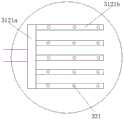
图1是本发明实施例的具有泄压功能的电压力锅的结构示意图;1 is a schematic structural diagram of an electric pressure cooker with a pressure relief function according to an embodiment of the present invention;
图2-1是本发明一种实施例的射流管在内盖内的布置结构图;FIG. 2-1 is a structural diagram of the arrangement of the jet tube in the inner cover according to an embodiment of the present invention;
图2-2是本发明另一种实施例的射流管在内盖内的布置结构图;2-2 is a structural diagram of the arrangement of the jet tube in the inner cover according to another embodiment of the present invention;
图2-3是本发明又一种实施例的射流管在内盖内的布置结构图;2-3 is a structural diagram of the arrangement of the jet tube in the inner cover according to another embodiment of the present invention;
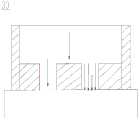
图3-1是本发明一种实施例隔板与喷嘴的组合结构示意图;Figure 3-1 is a schematic diagram of the combined structure of a separator and a nozzle according to an embodiment of the present invention;
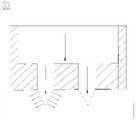
图3-2是本发明另一种实施例隔板与喷嘴的组合结构示意图;3-2 is a schematic diagram of the combined structure of a separator and a nozzle according to another embodiment of the present invention;
图3-3是本发明又一种实施例隔板与喷嘴的组合结构示意图;3-3 is a schematic diagram of the combined structure of a separator and a nozzle according to another embodiment of the present invention;
图3-4是本发明又一种实施例隔板与喷嘴的组合结构示意图。3-4 are schematic diagrams of the combined structure of a separator and a nozzle according to another embodiment of the present invention.
图中,In the figure,
100-电压力锅;100- electric pressure cooker;
10-锅体;10-pot body;
20-锅盖;21-外盖;22-隔板;221-第二通孔;23-内盖;20-pot cover; 21-outer cover; 22-partition plate; 221-second through hole; 23-inner cover;
311-储水箱;312-射流管;3121a-总管路;3121b-矩形管路;3122-环形管路;3123-圆形平板管路;313-回水管;32-射流泵;33-喷嘴;34-肋板。311-water storage tank; 312-jet pipe; 3121a-main pipeline; 3121b-rectangular pipeline; 3122-ring pipeline; 3123-circular plate pipeline; 313-return pipe; 32-jet pump; 33-nozzle; 34 - Ribs.
在附图中,相同的部件使用相同的附图标记。附图并未按照实际的比例绘制。In the drawings, the same components are given the same reference numerals. The drawings are not drawn to actual scale.
具体实施方式Detailed ways
下面将详细描述本发明的各个方面的特征和示例性实施例。在下面的详细描述中,提出了许多具体细节,以便提供对本发明的全面理解。但是,对于本领域技术人员来说很明显的是,本发明可以在不需要这些具体细节中的一些细节的情况下实施。下面对实施例的描述仅仅是为了通过示出本发明的示例来提供对本发明的更好的理解。在附图和下面的描述中,至少部分的公知结构和技术没有被示出,以便避免对本发明造成不必要的模糊;并且,为了清晰,可能夸大了部分结构的尺寸。此外,下文中所描述的特征、结构或特性可以以任何合适的方式结合在一个或更多实施例中。Features and exemplary embodiments of various aspects of the invention are described in detail below. In the following detailed description, numerous specific details are set forth in order to provide a thorough understanding of the present invention. However, it will be apparent to one skilled in the art that the present invention may be practiced without some of these specific details. The following description of the embodiments is only intended to provide a better understanding of the present invention by illustrating examples of the invention. In the drawings and the following description, at least some well-known structures and techniques are not shown in order to avoid unnecessarily obscuring the present invention; and, the dimensions of some structures may be exaggerated for clarity. Furthermore, the features, structures or characteristics described below may be combined in any suitable manner in one or more embodiments.
下述描述中出现的方位词均为图中示出的方向,并不是对本发明的具有泄压功能的电压力锅100的具体结构进行限定。在本发明的描述中,还需要说明的是,除非另有明确的规定和限定,术语“安装”、“连接”应做广义理解,例如,可以是固定连接,也可以是可拆卸连接,或一体地连接;可以是直接相连,也可以间接相连。对于本领域的普通技术人员而言,可视具体情况理解上述术语在本发明中的具体含义。The orientation words appearing in the following description are all directions shown in the figures, and are not intended to limit the specific structure of the
本发明实施例提供一种具有泄压功能的电压力锅100,利用射流冲击冷却技术加快锅盖20内盖23的散热,快速降低锅内温度,加快锅内压力下降,缩短泄压时间。The embodiment of the present invention provides an
为了更好地理解本发明,下面结合图1至图3-4根据本发明实施例的具有泄压功能的电压力锅100进行详细描述。For a better understanding of the present invention, the
请参阅图1至图3-4,图1示出了本发明实施例的具有泄压功能的电压力锅100的结构示意图;图2-1示出了本发明一种实施例的射流管312在内盖23内的布置结构图;图2-2示出了本发明另一种实施例的射流管312在内盖23内的布置结构图;图2-3示出了本发明又一种实施例的射流管312在内盖23内的布置结构图;图3-1示出了本发明一种实施例隔板22与喷嘴33的组合结构示意图;图3-2示出了本发明另一种实施例隔板22与喷嘴33的组合结构示意图;图3-3示出了本发明又一种实施例隔板22与喷嘴33的组合结构示意图;图3-4示出了本发明又一种实施例隔板22与喷嘴33的组合结构示意图。Please refer to FIGS. 1 to 3-4. FIG. 1 shows a schematic structural diagram of an
请参阅图1至图3-4,本发明实施例提供的一种具有泄压功能的电压力锅100,包括:锅体10、锅盖20及射流冲击冷却装置,锅盖20与锅体10配套使用,射流冲击冷却装置包括循环水路、连接于循环水路上的射流泵32以及设置于锅盖20内的喷射装置;其中,喷射装置与循环水路相连通。Referring to FIGS. 1 to 3-4 , an
本发明实施例提供的一种具有泄压功能的电压力锅100,循环水路包括储水箱311、射流管312以及回水管313;其中,储水箱311、射流泵32、射流管312及回水管313顺次连接为一水流回路,且喷射装置与射流管312相连通,射流管312内的冷却水可由喷射装置喷出。在一些可选的实施例中,储水箱311及射流泵32均设置于锅体10的侧壁内。In an
本发明实施例提供的一种具有泄压功能的电压力锅100,射流管312部分设置于锅盖20内。设置于锅盖20内的射流管312包括总管路3121a及均与总管路3121a相连通的多排矩形管路3121b;或者,设置于锅盖20内的射流管312包括至少一个环形管路3122;或者,设置于锅盖20内的射流管312包括圆形平板管路3123。The embodiment of the present invention provides an
本发明实施例提供的一种具有泄压功能的电压力锅100,锅盖20包括包括层叠设置的外盖21、隔板22及内盖23;其中,外盖21、隔板22及内盖23间隔设置。位于锅盖20内的射流管312设置于外盖21与隔板22之间;或者,外盖21的内壁与隔板22面向外盖21的一侧表面共同形成位于锅盖20内的射流管312。The embodiment of the present invention provides an
本发明实施例提供的一种具有泄压功能的电压力锅100,射流管312上靠近锅体10的一侧设置有多个第一通孔,喷射装置包括多个与第一通孔一一对应设置的喷嘴33。隔板22上设有多个与第一通孔一一对应设置的第二通孔221。喷嘴33为实心结构,且喷嘴33与隔板22上围绕形成第二通孔221的侧壁之间具有间隙,冷却水可由间隙喷出;喷嘴33通过多个肋板34与隔板22上围绕形成第二通孔221的侧壁相连接,且多个肋板34沿第二通孔221的周向间隔设置。或者,在一些可选的实施例中喷嘴33为空心结构,喷嘴33上设有沿垂直于隔板22厚度方向上贯通喷嘴33的喷水孔,冷却水可由喷水孔喷出。可选的,如图3-2所示,喷嘴33为空心圆锥形喷嘴33;如图1所示,喷嘴33为条缝隙喷嘴33;如图3-3所示,喷嘴33为压力旋流喷嘴33;如图3-4所示,喷嘴33为平孔喷嘴33;可以理解的是,在其他实施例中,喷嘴33还可以为柱形喷嘴33。The embodiment of the present invention provides an
请进一步参阅图1,本发明实施例提供的一种具有泄压功能的电压力锅100的各个部件的作用如下:Referring further to FIG. 1 , the functions of each component of an
储水箱311,用于储存冷却锅盖20内盖23的射流冷却水,储水箱311内安装有过滤滤网,滤网可以过滤进入射流泵32的冷却水杂质,有效防止射流喷嘴33堵塞;射流泵32,用于给冷却水加压,通过管路将高压冷却水输送到射流管312,保证冷却水从喷嘴33喷出所需的射流压力;射流管312,如图2-1至2-3所示,射流管312由多排矩形管路3121b、环形管路3122或圆形平板管路3123构成,用于布置多个射流喷嘴33;喷嘴33,用于产生冲击射流,喷嘴33喷射出的高速冷却水冲击锅盖20内盖23,快速冷却锅盖20内盖23,喷嘴33形状可以选用圆形喷嘴33、窄缝型喷嘴33或柱形喷嘴33,圆形喷嘴33孔径范围为0.5mm~3mm,柱形喷嘴33等效孔径范围为0.3mm~3mm,窄缝型喷嘴33条形缝宽度范围为0.5mm~3mm;回水管313,将冲击射流吸收内盖23热量后的冷却水输送回储水箱311,形成循环冷却水利用;储水箱311进水口,通过储水箱311进水口进行冷却水添加,同时用于冷却过程中的冷却水回收;锅盖20,锅盖20内安装射流管312和喷嘴33等部分射流冲击冷却装置;锅体10,用于盛放烹饪食物,烹饪过程中锅内存在高温高压蒸汽;内盖23,与锅内蒸汽直接接触,通过冷却水射流冲击内盖23,与锅内高温高压蒸汽进行热量交换,将高温高压蒸汽的热量带走,降低锅内温度和压力,实现快速泄压。The
本发明实施例提供的一种具有泄压功能的电压力锅100的工作原理为:以储水箱311内的冷却水为冷却介质,通过射流泵32加压冷却水为射流冲击提供压力,高压冷却水通过射流管312输送到喷嘴33,通过圆形或窄缝型喷嘴33直接喷射到锅盖20内盖23表面进行冷却,射流冲击冷却由于冷却水直接接触到需要冷却的表面,高动量冲击产生很强的冷却效果,冷却水快速从内盖23吸收热量,快速降低内盖23温度,加快锅内高温高压蒸汽向冷却水散热,进而实现锅内快速降温泄压。射流冲击冷却内盖23表面平均换热系数高达10000W/m2,是普通水冷平均换热系数的10倍左右。射流管312由多排矩形管路3121b、环形管路3122或圆形平板管路3123构成,布置多个射流喷嘴33,保证射流喷射冷却水覆盖锅盖20内盖23表面,增大射流冷却水与内盖23的换热面积,增强内盖23的散热能力。采用射流冲击冷却可以实现电压力锅100快速泄压,缩短泄压时间,比普通水冷泄压时间缩短30%以上;同时,由于射流冲击冷却换热能力强,在冷却水温度较高的情况下,仍然可以保证很强的冷却效果,因此,射流冲击所需冷却水水量比普通水冷减少30%以上,可以减小储水箱311和电压力锅100整机体积和重量。The working principle of the
本发明实施例提供的一种具有泄压功能的电压力锅100,采用射流冲击冷却,能够产生很强的冷却效果,快速冷却锅盖20内盖23,将锅内高温高压蒸汽的热量快速带走,降低锅内温度和压力,缩短电压力锅100泄压时间,实现快速泄压,同时可以减少冷却水的需求,减小储水箱311的体积和电压力锅100整机体积和重量。An
虽然已经参考可选择的实施例对本发明进行了描述,但在不脱离本发明的范围的情况下,可以对其进行各种改进并且可以用等效物替换其特征在于的部件。尤其是,只要不存在结构冲突,各个实施例中所提到的各项技术特征均可以任意方式组合起来。本发明并不局限于文中公开的特定实施例,而是包括落入权利要求的范围内的所有技术方案。While the present invention has been described with reference to alternative embodiments, various modifications may be made and equivalents may be substituted for the features featured therein without departing from the scope of the invention. In particular, as long as there is no structural conflict, each technical feature mentioned in each embodiment can be combined in any manner. The present invention is not limited to the specific embodiments disclosed herein, but includes all technical solutions falling within the scope of the claims.
Claims (12)
Translated fromChinesePriority Applications (1)
| Application Number | Priority Date | Filing Date | Title |
|---|---|---|---|
| CN201911098546.4ACN110720826A (en) | 2019-11-12 | 2019-11-12 | An electric pressure cooker with pressure relief function |
Applications Claiming Priority (1)
| Application Number | Priority Date | Filing Date | Title |
|---|---|---|---|
| CN201911098546.4ACN110720826A (en) | 2019-11-12 | 2019-11-12 | An electric pressure cooker with pressure relief function |
Publications (1)
| Publication Number | Publication Date |
|---|---|
| CN110720826Atrue CN110720826A (en) | 2020-01-24 |
Family
ID=69223917
Family Applications (1)
| Application Number | Title | Priority Date | Filing Date |
|---|---|---|---|
| CN201911098546.4APendingCN110720826A (en) | 2019-11-12 | 2019-11-12 | An electric pressure cooker with pressure relief function |
Country Status (1)
| Country | Link |
|---|---|
| CN (1) | CN110720826A (en) |
Cited By (3)
| Publication number | Priority date | Publication date | Assignee | Title |
|---|---|---|---|---|
| US11134808B2 (en) | 2020-03-30 | 2021-10-05 | Sharkninja Operating Llc | Cooking device and components thereof |
| US11627834B2 (en) | 2017-08-09 | 2023-04-18 | Sharkninja Operating Llc | Cooking system for cooking food |
| US11751710B2 (en) | 2019-02-25 | 2023-09-12 | Sharkninja Operating Llc | Guard for cooking system |
Citations (4)
| Publication number | Priority date | Publication date | Assignee | Title |
|---|---|---|---|---|
| CN201767749U (en)* | 2010-05-24 | 2011-03-23 | 九阳股份有限公司 | Electric pressure appliance with cooling device |
| CN106889877A (en)* | 2017-04-14 | 2017-06-27 | 广东美的智美科技有限公司 | Pressure cooking appliance |
| CN106889878A (en)* | 2017-04-14 | 2017-06-27 | 广东美的智美科技有限公司 | Pressure cooking appliance |
| CN211748828U (en)* | 2019-11-12 | 2020-10-27 | 珠海格力电器股份有限公司 | Electric pressure cooker with pressure relief function |
- 2019
- 2019-11-12CNCN201911098546.4Apatent/CN110720826A/enactivePending
Patent Citations (4)
| Publication number | Priority date | Publication date | Assignee | Title |
|---|---|---|---|---|
| CN201767749U (en)* | 2010-05-24 | 2011-03-23 | 九阳股份有限公司 | Electric pressure appliance with cooling device |
| CN106889877A (en)* | 2017-04-14 | 2017-06-27 | 广东美的智美科技有限公司 | Pressure cooking appliance |
| CN106889878A (en)* | 2017-04-14 | 2017-06-27 | 广东美的智美科技有限公司 | Pressure cooking appliance |
| CN211748828U (en)* | 2019-11-12 | 2020-10-27 | 珠海格力电器股份有限公司 | Electric pressure cooker with pressure relief function |
Cited By (7)
| Publication number | Priority date | Publication date | Assignee | Title |
|---|---|---|---|---|
| US11627834B2 (en) | 2017-08-09 | 2023-04-18 | Sharkninja Operating Llc | Cooking system for cooking food |
| US11751710B2 (en) | 2019-02-25 | 2023-09-12 | Sharkninja Operating Llc | Guard for cooking system |
| US12226039B2 (en) | 2019-02-25 | 2025-02-18 | Sharkninja Operating Llc | Guard for cooking system |
| US11134808B2 (en) | 2020-03-30 | 2021-10-05 | Sharkninja Operating Llc | Cooking device and components thereof |
| US11647861B2 (en) | 2020-03-30 | 2023-05-16 | Sharkninja Operating Llc | Cooking device and components thereof |
| US11678765B2 (en) | 2020-03-30 | 2023-06-20 | Sharkninja Operating Llc | Cooking device and components thereof |
| US11969118B2 (en) | 2020-03-30 | 2024-04-30 | Sharkninja Operating Llc | Cooking device and components thereof |
Similar Documents
| Publication | Publication Date | Title |
|---|---|---|
| CN110720826A (en) | An electric pressure cooker with pressure relief function | |
| CN109008590B (en) | Condensate water reflux structure of electric steaming furnace | |
| CN211748828U (en) | Electric pressure cooker with pressure relief function | |
| CN211879185U (en) | Cooling device for single-phase dry-type transformer | |
| CN212690274U (en) | Double-effect cooling device of compressor of natural gas long-distance pipeline gas station | |
| WO2024141116A1 (en) | Gas water heater | |
| WO2024141115A1 (en) | Gas water heater | |
| CN110367812B (en) | Safe and energy-saving cooking utensil | |
| CN218432901U (en) | Alcohol-based fuel storage jar with cooling effect | |
| CN201526947U (en) | Environment-friendly atmospheric high-temperature steam generator | |
| CN211146968U (en) | Spray absorber | |
| CN216049393U (en) | Slow flow pipeline joint for heat exchanger and heat exchanger | |
| CN202885587U (en) | Air-cooled gas cooler | |
| CN212326131U (en) | Steam cooking apparatus | |
| CN209639574U (en) | A Microchannel Heat Exchanger Structure with Nozzles | |
| CN217515377U (en) | Jet nozzle of aircraft engine | |
| CN107259972B (en) | High-temperature boiler | |
| CN206777179U (en) | Cooling water cup based on Enhancing Heat Transfer With Jet Impingement technology | |
| CN208186750U (en) | A kind of diffuser design | |
| CN111678340A (en) | Zinc alloy energy-saving environment-friendly gas crucible furnace | |
| CN218074606U (en) | Oven with steam cooking function | |
| CN206700032U (en) | Steam valve and electric cooker | |
| CN218588086U (en) | Energy-conserving efficient deep-fry device | |
| CN211902812U (en) | Quick steam generator | |
| CN212585463U (en) | An energy-saving and environmentally friendly gas crucible furnace |
Legal Events
| Date | Code | Title | Description |
|---|---|---|---|
| PB01 | Publication | ||
| PB01 | Publication | ||
| SE01 | Entry into force of request for substantive examination | ||
| SE01 | Entry into force of request for substantive examination |