CN110716213B - Voice navigation positioning system based on GPS - Google Patents
Voice navigation positioning system based on GPSDownload PDFInfo
- Publication number
- CN110716213B CN110716213BCN201911051913.5ACN201911051913ACN110716213BCN 110716213 BCN110716213 BCN 110716213BCN 201911051913 ACN201911051913 ACN 201911051913ACN 110716213 BCN110716213 BCN 110716213B
- Authority
- CN
- China
- Prior art keywords
- rod
- camera
- lifting rod
- electrically connected
- arc
- Prior art date
- Legal status (The legal status is an assumption and is not a legal conclusion. Google has not performed a legal analysis and makes no representation as to the accuracy of the status listed.)
- Active
Links
Images


Classifications
- G—PHYSICS
- G01—MEASURING; TESTING
- G01S—RADIO DIRECTION-FINDING; RADIO NAVIGATION; DETERMINING DISTANCE OR VELOCITY BY USE OF RADIO WAVES; LOCATING OR PRESENCE-DETECTING BY USE OF THE REFLECTION OR RERADIATION OF RADIO WAVES; ANALOGOUS ARRANGEMENTS USING OTHER WAVES
- G01S19/00—Satellite radio beacon positioning systems; Determining position, velocity or attitude using signals transmitted by such systems
- G01S19/01—Satellite radio beacon positioning systems transmitting time-stamped messages, e.g. GPS [Global Positioning System], GLONASS [Global Orbiting Navigation Satellite System] or GALILEO
- G01S19/13—Receivers
- G01S19/14—Receivers specially adapted for specific applications
- G—PHYSICS
- G01—MEASURING; TESTING
- G01C—MEASURING DISTANCES, LEVELS OR BEARINGS; SURVEYING; NAVIGATION; GYROSCOPIC INSTRUMENTS; PHOTOGRAMMETRY OR VIDEOGRAMMETRY
- G01C21/00—Navigation; Navigational instruments not provided for in groups G01C1/00 - G01C19/00
- G01C21/26—Navigation; Navigational instruments not provided for in groups G01C1/00 - G01C19/00 specially adapted for navigation in a road network
- G01C21/34—Route searching; Route guidance
- G01C21/36—Input/output arrangements for on-board computers
- G01C21/3626—Details of the output of route guidance instructions
- G01C21/3629—Guidance using speech or audio output, e.g. text-to-speech
- G—PHYSICS
- G01—MEASURING; TESTING
- G01C—MEASURING DISTANCES, LEVELS OR BEARINGS; SURVEYING; NAVIGATION; GYROSCOPIC INSTRUMENTS; PHOTOGRAMMETRY OR VIDEOGRAMMETRY
- G01C21/00—Navigation; Navigational instruments not provided for in groups G01C1/00 - G01C19/00
- G01C21/26—Navigation; Navigational instruments not provided for in groups G01C1/00 - G01C19/00 specially adapted for navigation in a road network
- G01C21/34—Route searching; Route guidance
- G01C21/36—Input/output arrangements for on-board computers
- G01C21/3697—Output of additional, non-guidance related information, e.g. low fuel level
- G—PHYSICS
- G01—MEASURING; TESTING
- G01S—RADIO DIRECTION-FINDING; RADIO NAVIGATION; DETERMINING DISTANCE OR VELOCITY BY USE OF RADIO WAVES; LOCATING OR PRESENCE-DETECTING BY USE OF THE REFLECTION OR RERADIATION OF RADIO WAVES; ANALOGOUS ARRANGEMENTS USING OTHER WAVES
- G01S19/00—Satellite radio beacon positioning systems; Determining position, velocity or attitude using signals transmitted by such systems
- G01S19/38—Determining a navigation solution using signals transmitted by a satellite radio beacon positioning system
- G01S19/39—Determining a navigation solution using signals transmitted by a satellite radio beacon positioning system the satellite radio beacon positioning system transmitting time-stamped messages, e.g. GPS [Global Positioning System], GLONASS [Global Orbiting Navigation Satellite System] or GALILEO
- G01S19/42—Determining position
- G—PHYSICS
- G11—INFORMATION STORAGE
- G11B—INFORMATION STORAGE BASED ON RELATIVE MOVEMENT BETWEEN RECORD CARRIER AND TRANSDUCER
- G11B31/00—Arrangements for the associated working of recording or reproducing apparatus with related apparatus
Landscapes
- Engineering & Computer Science (AREA)
- Radar, Positioning & Navigation (AREA)
- Remote Sensing (AREA)
- General Physics & Mathematics (AREA)
- Physics & Mathematics (AREA)
- Automation & Control Theory (AREA)
- Multimedia (AREA)
- Computer Networks & Wireless Communication (AREA)
- General Health & Medical Sciences (AREA)
- Audiology, Speech & Language Pathology (AREA)
- Health & Medical Sciences (AREA)
- Position Fixing By Use Of Radio Waves (AREA)
- Studio Devices (AREA)
- Navigation (AREA)
- Traffic Control Systems (AREA)
Abstract
Description
Translated fromChinese技术领域technical field
本发明涉及一种基于GPS的语音导航定位系统。The invention relates to a voice navigation and positioning system based on GPS.
背景技术Background technique
汽车行业在中国属于朝阳产业,汽车保有量逐渐增加。在汽车工业的大发展阶段,GPS(Global Positioning System,全球定位系统)导航系统也成为每辆汽车的必备配件。然而,GPS导航系统除了导航作用外,并无其他功能,导致其作用单一。The automobile industry is a sunrise industry in China, and the number of automobiles is gradually increasing. In the stage of great development of the automobile industry, the GPS (Global Positioning System, Global Positioning System) navigation system has also become an essential accessory for every automobile. However, the GPS navigation system has no other functions except the navigation function, resulting in a single function.
发明内容Contents of the invention
基于此,有必要提供一种功能较多的基于GPS的语音导航定位系统。Based on this, it is necessary to provide a voice navigation and positioning system based on GPS with more functions.
一种基于GPS的语音导航定位系统,包括导航仪本体、语音输出器件、控制器与播放器,所述导航仪本体上设置有照明灯,所述语音输出器件与所述导航仪本体电性连接,用于输出导航语音,所述语音输出器件及所述播放器均与所述控制器电性连接,当所述控制器判断所述语音输出器件闲置时,所述控制器控制所述播放器播放音乐。A voice navigation and positioning system based on GPS, comprising a navigator body, a voice output device, a controller and a player, the navigator body is provided with a lighting lamp, and the voice output device is electrically connected to the navigator body , for outputting navigation voice, the voice output device and the player are electrically connected to the controller, when the controller judges that the voice output device is idle, the controller controls the player play music.
在其中一个实施方式中,所述导航仪本体包括壳体、显示屏以及电路模块,所述电路模块设置于所述壳体内,所述显示屏设置于所述壳体上并与所述电路模块电性连接。In one of the embodiments, the navigator body includes a housing, a display screen and a circuit module, the circuit module is arranged in the housing, the display screen is arranged on the housing and connected to the circuit module electrical connection.
在其中一个实施方式中,所述电路模块包括芯片、天线、处理器与内存,所述天线、所述处理器及所述内存均与所述芯片电性连接。In one embodiment, the circuit module includes a chip, an antenna, a processor, and a memory, and the antenna, the processor, and the memory are all electrically connected to the chip.
在其中一个实施方式中,所述语音输出器件与所述处理器电性连接。In one of the implementation manners, the voice output device is electrically connected with the processor.
在其中一个实施方式中,所述壳体上形成有围绕框,所述围绕框围绕所述显示屏,所述照明灯安装于所述围绕框上。In one embodiment, a surrounding frame is formed on the casing, the surrounding frame surrounds the display screen, and the lighting lamp is installed on the surrounding frame.
在其中一个实施方式中,所述壳体上设置有插槽,所述插槽内设置有电性接触片,所述照明灯插设于所述插槽内并与所述电性接触片电性连接。In one embodiment, a slot is provided on the housing, and an electrical contact piece is arranged in the slot, and the lighting lamp is inserted in the slot and electrically connected to the electrical contact piece. sexual connection.
在其中一个实施方式中,所述插槽为矩形插槽,所述照明灯包括灯座与设置于所述灯座上的灯珠,所述灯座的底部设置有插设体,所述插设体插设于所述插槽内。In one embodiment, the slot is a rectangular slot, the lighting lamp includes a lamp holder and a lamp bead arranged on the lamp holder, an insertion body is provided at the bottom of the lamp holder, and the insertion body The body is inserted into the slot.
在其中一个实施方式中,所述插设体内设置有接电片,所述接电片为弹性片,所述接电片抵接于所述电性接触片上。In one of the embodiments, a power connection piece is arranged in the insertion body, the power connection piece is an elastic piece, and the power connection piece abuts on the electrical contact piece.
在其中一个实施方式中,所述电路模块还包括供电电路,所述供电电路与所述电性接触片电性连接,用于所述照明灯供电。In one embodiment, the circuit module further includes a power supply circuit, the power supply circuit is electrically connected to the electrical contact piece, and is used for supplying power to the illuminating lamp.
在其中一个实施方式中,所述壳体为矩形壳体,且由塑胶材料制成。In one embodiment, the housing is a rectangular housing made of plastic material.
所述基于GPS的语音导航定位系统在使用时,所述导航仪本体能够进行导航并通过所述语音输出器件播放导航语音,而在导航语音的播放间隔中,所述控制器控制所述播放器播放音乐。另外,所述照明灯能够对车内进行照明。因此所述基于GPS的语音导航定位系统集成了导航、播放音乐以及照明三项功能,提高了其娱乐性能。When the voice navigation and positioning system based on GPS is in use, the navigator body can perform navigation and play the navigation voice through the voice output device, and in the playing interval of the navigation voice, the controller controls the player play music. In addition, the lighting lamp can illuminate the interior of the vehicle. Therefore, the GPS-based voice navigation and positioning system integrates three functions of navigation, playing music and lighting, and improves its entertainment performance.
附图说明Description of drawings
图1为一实施例的基于GPS的语音导航定位系统的模块方框图。FIG. 1 is a module block diagram of a GPS-based voice navigation and positioning system according to an embodiment.
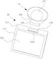
图2为一实施例的导航仪本体的立体示意图。Fig. 2 is a three-dimensional schematic diagram of a navigator body according to an embodiment.
图3为一实施例的摄像头及摄像组件的立体分解示意图。FIG. 3 is a three-dimensional exploded schematic diagram of a camera and a camera assembly according to an embodiment.
图4为一实施例的摄像组件的部分结构的立体示意图。FIG. 4 is a perspective schematic diagram of a partial structure of a camera assembly according to an embodiment.
具体实施方式Detailed ways
为了便于理解本发明,下面将参照相关附图对本发明进行更全面的描述。附图中给出了本发明的较佳实施方式。但是,本发明可以以许多不同的形式来实现,并不限于本文所描述的实施方式。相反地,提供这些实施方式的目的是使对本发明的公开内容理解的更加透彻全面。In order to facilitate the understanding of the present invention, the present invention will be described more fully below with reference to the associated drawings. Preferred embodiments of the invention are shown in the accompanying drawings. However, the present invention can be embodied in many different forms and is not limited to the embodiments described herein. On the contrary, the purpose of providing these embodiments is to make the disclosure of the present invention more thorough and comprehensive.
需要说明的是,当元件被称为“固定于”另一个元件,它可以直接在另一个元件上或者也可以存在居中的元件。当一个元件被认为是“连接”另一个元件,它可以是直接连接到另一个元件或者可能同时存在居中元件。本文所使用的术语“垂直的”、“水平的”、“左”、“右”以及类似的表述只是为了说明的目的,并不表示是唯一的实施方式。It should be noted that when an element is referred to as being “fixed” to another element, it can be directly on the other element or there can also be an intervening element. When an element is referred to as being "connected to" another element, it can be directly connected to the other element or intervening elements may also be present. The terms "vertical," "horizontal," "left," "right," and similar expressions are used herein for purposes of illustration only and are not intended to represent the only embodiments.
除非另有定义,本文所使用的所有的技术和科学术语与属于本发明的技术领域的技术人员通常理解的含义相同。本文中所使用的术语只是为了描述具体的实施方式的目的,不是旨在于限制本发明。本文所使用的术语“及/或”包括一个或多个相关的所列项目的任意的和所有的组合。Unless otherwise defined, all technical and scientific terms used herein have the same meaning as commonly understood by one of ordinary skill in the technical field of the invention. The terms used herein are for the purpose of describing specific embodiments only, and are not intended to limit the present invention. As used herein, the term "and/or" includes any and all combinations of one or more of the associated listed items.
本发明涉及一种基于GPS的语音导航定位系统。例如,所述基于GPS的语音导航定位系统包括导航仪本体、语音输出器件、控制器与播放器,所述导航仪本体上设置有照明灯。例如,所述语音输出器件与所述导航仪本体电性连接,用于输出导航语音。例如,所述语音输出器件及所述播放器均与所述控制器电性连接,当所述控制器判断所述语音输出器件闲置时,所述控制器控制所述播放器播放音乐。The invention relates to a voice navigation and positioning system based on GPS. For example, the GPS-based voice navigation and positioning system includes a navigator body, a voice output device, a controller and a player, and the navigator body is provided with a lighting lamp. For example, the voice output device is electrically connected to the navigator body for outputting navigation voice. For example, both the voice output device and the player are electrically connected to the controller, and when the controller determines that the voice output device is idle, the controller controls the player to play music.
请参阅图1及图2,一种基于GPS的语音导航定位系统100,包括导航仪本体10、语音输出器件20、控制器30与播放器40,所述导航仪本体上设置有照明灯11,所述语音输出器件与所述导航仪本体电性连接,用于输出导航语音,所述语音输出器件及所述播放器均与所述控制器电性连接,当所述控制器判断所述语音输出器件闲置时,所述控制器控制所述播放器播放音乐。例如,基于GPS的语音导航定位系统适用于车辆上。Please refer to Fig. 1 and Fig. 2, a kind of voice
例如,所述基于GPS的语音导航定位系统在使用时,所述导航仪本体能够进行导航并通过所述语音输出器件播放导航语音,而在导航语音的播放间隔中,所述控制器控制所述播放器播放音乐。另外,所述照明灯能够对车内进行照明。因此所述基于GPS的语音导航定位系统集成了导航、播放音乐以及照明三项功能,提高了其娱乐性能。For example, when the voice navigation and positioning system based on GPS is in use, the navigator body can perform navigation and play navigation voice through the voice output device, and during the playing interval of the navigation voice, the controller controls the The player plays music. In addition, the lighting lamp can illuminate the interior of the vehicle. Therefore, the GPS-based voice navigation and positioning system integrates three functions of navigation, playing music and lighting, and improves its entertainment performance.
例如,为了便于插设所述照明灯,所述导航仪本体包括壳体111、显示屏112以及电路模块115,所述电路模块设置于所述壳体内,所述显示屏设置于所述壳体上并与所述电路模块电性连接。所述电路模块包括芯片1151、天线1152、处理器1153与内存1154,所述天线、所述处理器及所述内存均与所述芯片电性连接。所述语音输出器件与所述处理器电性连接。所述壳体上形成有围绕框113,所述围绕框围绕所述显示屏,所述照明灯安装于所述围绕框上。所述壳体上设置有插槽114,所述插槽内设置有电性接触片1141,所述照明灯插设于所述插槽内并与所述电性接触片电性连接。通过于所述壳体上设置插槽并于所述插槽内设置电性接触片,从而方便将所述照明灯插设于所述插槽内,进而为所述照明灯供电。同时当需要移除所述照明灯时,其也比较方便。For example, in order to facilitate the insertion of the lighting lamp, the navigator body includes a
例如,为了便有插设所述照明灯,所述插槽为矩形插槽,所述照明灯包括灯座116与设置于所述灯座上的灯珠117,所述灯座的底部设置有插设体118,所述插设体插设于所述插槽内。所述插设体内设置有接电片,所述接电片为弹性片,所述接电片抵接于所述电性接触片上。所述电路模块还包括供电电路1155,所述供电电路与所述电性接触片电性连接,用于所述照明灯供电。所述壳体为矩形壳体,且由塑胶材料制成。由于所述照明灯具有灯座,且所述灯座的插设体内设置有接电片,从而可以较为方便地时所述接电片发生弹性形变以适应所述电性接触片的形状,进而利用个所属电路模块的供电电路为所述照明灯供电。For example, in order to insert the lighting lamp, the slot is a rectangular slot, the lighting lamp includes a
例如,进一步地,请一并参阅图3及图4,为了便于观察车辆的状况以及周边情况,以防范危险状况,所述基于GPS的语音导航定位系统还包括摄像头50,所述摄像头及所述显示屏均与所述控制器电性连接,所述摄像头设置于车顶,所述导航仪本体设置于驾驶室内,所述控制器控制所述摄像头拍摄车辆的周边图像并控制所述显示屏显示所述周边图像,例如,所述显示屏上形成有周边显示区,所述周边图像显示于所述周边显示区上,从而方便司机及时观察周边道路情况与车辆的自身情况,例如是否着火现象。例如,为了便于控制所述摄像头的升降,以方便观察,所述基于GPS的语音导航定位系统包括摄像组件60,所述摄像组件包括升降杆61与弹性拉条62,所述升降杆的一端固定于驾驶室内的置物板上,另一端穿设于车顶中并暴露于车外侧,所述升降杆的顶部高于车顶。所述升降杆内形成有插设通道611,所述摄像头的底部形成有安装体51,所述安装体活动地插设于所述插设通道内,所述弹性拉条设置于所述插设通道内,所述弹性拉条的一端连接所述摄像头,另一端连接所述升降杆的中部。为了便于对所述摄像头进行导向,所述安装体的底部设置有插杆52,所述插杆滑动地设置于所述插设通道内,所述弹性拉条的端部连接于所述插杆的底部。通过设置所述弹性拉条,从而可以使得所述摄像头稳定地定位于所述升降杆的顶部。For example, further, please refer to Fig. 3 and Fig. 4 together, in order to observe the situation of the vehicle and surrounding conditions, to prevent dangerous situations, the voice navigation and positioning system based on GPS also includes a
而为了便于调整所述摄像头的高度,以便于观测更远处的状况,例如后面堵车的状况,以及前方货车的前面道路状况,所述摄像组件还包括两个回位支撑条63、两个弧形横条64与旋转操作件65,所述升降杆的相对两侧设置有多个限位半环631,所述两个回位支撑条分别设置于所述升降杆的相对两侧,并分别连接于所述摄像头的安装体的相对两侧,所述回位支撑条穿设于所述升降杆一侧的多个限位半环中,所述回位支撑条的一端固定于所述升降杆上,另一端连接于所述摄像头的安装体上。所述两个回位支撑条上均形成有拱形部635,所述两个回位支撑条的拱形部互相远离。所述升降杆上垂直凸设有安装杆636,所述安装杆上垂直凸设有作动杆637,所述安装杆与所述升降杆均与所述作动杆垂直。所述作动杆的中部连接于所述安装杆的端部,所述两个弧形横条分别设置于所述作动杆的相对两端,所述两个弧形横条的中部转动地设置于所述作动杆上,所述弧形横条包括相对设置的联动端641与结合端643,所述两个弧形横条的结合端分别固定于所述两个回位支撑条的拱形部上。所述结合端处于所述拱形部的中间部位。所述旋转操作件穿设于所述两个弧形横条的联动端,通过旋转所述旋转操作件旋转,可以驱动所述两个弧形横条转动,进而驱使所述两个拱形部互相远离或者互相靠近,从而驱使所述回位支撑条发生弹性变形并于所述多个限位半环中伸长或者缩短,进一步地驱动位于所述升降杆顶部的摄像头上升或者下降,从而实现对摄像头的高度的调节。And for the convenience of adjusting the height of the camera, so as to observe the situation farther away, such as the situation of the traffic jam in the back, and the road conditions in front of the front truck, the camera assembly also includes two return support bars 63, two arc Shaped
例如,为了便于所述旋转操作件旋转,所述旋转操作件包括柱体651与操作环653,所述柱体的一端凸设有止脱环655,所述柱体的中部形成有螺纹段,所述螺纹段延伸至所述止脱环处,所述操作环螺合于所述柱体的螺纹段上,所述两个弧形横条的联动端均套设于所述柱体上,并均位于所述止脱环与所述操作环之间,通过施力旋转所述操作环即可通过所述操作环抵压所述两个联动端,调节所述两个联动端之间的距离,从而带动调节所述两个拱形部之间的距离。例如,为了方便与所述柱体连接,所述联动端上开设有腰形孔,所述腰形孔活动套设于所述柱体上,从而避免了所述弧形横条旋转带来的配合问题。例如,所述拱形部的长度为所述弧形横条的长度的4-6倍。通过调节所述两个弧形横条的联动端之间的距离,可以改变所述两个拱形部之间的距离,进而引起所述回位支撑条的长度的较大的改变,即可以起到一定的放大作用。即在本案中,通过所述旋转操作件较小距离的改变,而引起所述回位支撑条的较大距离的改变,从而实现对所述摄像头的高度较大的调节。例如,所述两个联动端之间设置有压簧68,所述压簧的弹性系数小于所述回位支撑条的弹性系数,即所述压簧较难变形。所述旋转操作件的初始位置即是释放所述两个联动端,所述压簧自然伸长并迫使所述两个联动端互相远离,使得所述两个弧形横条压持所述两个拱形部贴设于所述升降杆上。当旋转所述操作环时,驱动所述两个联动端互相靠近而压持所述压簧,此时所述两个拱形部利用自身弹性回复原位,进而缩短所述回位支撑条的长度。由于所述两个拱形部具有弹性,在无外力时能够回复原位,因此在旋转所述操作环时,所述两个拱形部的弹性能够使得操作更为省力。For example, in order to facilitate the rotation of the rotary operation member, the rotary operation member includes a
以上所述实施例的各技术特征可以进行任意的组合,为使描述简洁,未对上述实施例中的各个技术特征所有可能的组合都进行描述,然而,只要这些技术特征的组合不存在矛盾,都应当认为是本说明书记载的范围。The technical features of the above-mentioned embodiments can be combined arbitrarily. To make the description concise, all possible combinations of the technical features in the above-mentioned embodiments are not described. However, as long as there is no contradiction in the combination of these technical features, should be considered as within the scope of this specification.
以上所述实施方式仅表达了本发明的几种实施方式,其描述较为具体和详细,但并不能因此而理解为对本发明专利范围的限制。应当指出的是,对于本领域的普通技术人员来说,在不脱离本发明构思的前提下,还可以做出若干变形和改进,这些都属于本发明的保护范围。因此,本发明专利的保护范围应以所附权利要求为准。The above-mentioned embodiments only express several embodiments of the present invention, and the description thereof is relatively specific and detailed, but should not be construed as limiting the patent scope of the present invention. It should be noted that those skilled in the art can make several modifications and improvements without departing from the concept of the present invention, and these all belong to the protection scope of the present invention. Therefore, the protection scope of the patent for the present invention should be based on the appended claims.
Claims (1)
Priority Applications (1)
| Application Number | Priority Date | Filing Date | Title |
|---|---|---|---|
| CN201911051913.5ACN110716213B (en) | 2018-12-27 | 2018-12-27 | Voice navigation positioning system based on GPS |
Applications Claiming Priority (2)
| Application Number | Priority Date | Filing Date | Title |
|---|---|---|---|
| CN201811609223.2ACN109612498B (en) | 2018-12-27 | 2018-12-27 | A Voice Navigation and Positioning System Based on GPS |
| CN201911051913.5ACN110716213B (en) | 2018-12-27 | 2018-12-27 | Voice navigation positioning system based on GPS |
Related Parent Applications (1)
| Application Number | Title | Priority Date | Filing Date |
|---|---|---|---|
| CN201811609223.2ADivisionCN109612498B (en) | 2018-12-27 | 2018-12-27 | A Voice Navigation and Positioning System Based on GPS |
Publications (2)
| Publication Number | Publication Date |
|---|---|
| CN110716213A CN110716213A (en) | 2020-01-21 |
| CN110716213Btrue CN110716213B (en) | 2022-11-04 |
Family
ID=66012717
Family Applications (2)
| Application Number | Title | Priority Date | Filing Date |
|---|---|---|---|
| CN201911051913.5AActiveCN110716213B (en) | 2018-12-27 | 2018-12-27 | Voice navigation positioning system based on GPS |
| CN201811609223.2AActiveCN109612498B (en) | 2018-12-27 | 2018-12-27 | A Voice Navigation and Positioning System Based on GPS |
Family Applications After (1)
| Application Number | Title | Priority Date | Filing Date |
|---|---|---|---|
| CN201811609223.2AActiveCN109612498B (en) | 2018-12-27 | 2018-12-27 | A Voice Navigation and Positioning System Based on GPS |
Country Status (1)
| Country | Link |
|---|---|
| CN (2) | CN110716213B (en) |
Citations (7)
| Publication number | Priority date | Publication date | Assignee | Title |
|---|---|---|---|---|
| JP2011209258A (en)* | 2010-03-30 | 2011-10-20 | Shigeo Oritani | Chargeable portable navigation machine equipped with lcd capable of registering point to facility map and writing character, photographed image/character or the like, still image display function, moving image display function, photographing function, navigation/gps function, music reproduction function, sound recognition function, voice recognition function, and other peripheral connection/operation function |
| KR101130676B1 (en)* | 2011-05-11 | 2012-04-02 | 주식회사 씽크풀 | Digital system and providing method thereof |
| CN205630647U (en)* | 2016-02-19 | 2016-10-12 | 竺林坤 | Locate automobile console's intelligent robot |
| CN206107158U (en)* | 2016-08-31 | 2017-04-19 | 褚绍华 | Novel intelligent automobile terminal |
| CN107966157A (en)* | 2018-01-24 | 2018-04-27 | 江苏海事职业技术学院 | A kind of Multifunction travelling navigation equipment |
| CN108169777A (en)* | 2017-11-03 | 2018-06-15 | 北京讯业互联科技股份有限公司 | A kind of vehicle navigation apparatus based on triones navigation system |
| CN208075877U (en)* | 2017-09-04 | 2018-11-09 | 中讯邮电咨询设计院有限公司 | Bicycle speech navigation device |
Family Cites Families (5)
| Publication number | Priority date | Publication date | Assignee | Title |
|---|---|---|---|---|
| AR064237A1 (en)* | 2006-09-27 | 2009-03-25 | Tomtom Int Bv | PORTABLE NAVIGATION DEVICE |
| US20080147308A1 (en)* | 2006-12-18 | 2008-06-19 | Damian Howard | Integrating Navigation Systems |
| CN104033739A (en)* | 2014-06-10 | 2014-09-10 | 深圳市长江力伟股份有限公司 | Mobile lighting equipment |
| KR20160045353A (en)* | 2014-10-17 | 2016-04-27 | 현대자동차주식회사 | Audio video navigation, vehicle and controlling method of the audio video navigation |
| CN207321508U (en)* | 2017-08-17 | 2018-05-04 | 诸暨搏远网络科技有限公司 | A kind of multi-functional vehicle audio navigation arrangement |
- 2018
- 2018-12-27CNCN201911051913.5Apatent/CN110716213B/enactiveActive
- 2018-12-27CNCN201811609223.2Apatent/CN109612498B/enactiveActive
Patent Citations (7)
| Publication number | Priority date | Publication date | Assignee | Title |
|---|---|---|---|---|
| JP2011209258A (en)* | 2010-03-30 | 2011-10-20 | Shigeo Oritani | Chargeable portable navigation machine equipped with lcd capable of registering point to facility map and writing character, photographed image/character or the like, still image display function, moving image display function, photographing function, navigation/gps function, music reproduction function, sound recognition function, voice recognition function, and other peripheral connection/operation function |
| KR101130676B1 (en)* | 2011-05-11 | 2012-04-02 | 주식회사 씽크풀 | Digital system and providing method thereof |
| CN205630647U (en)* | 2016-02-19 | 2016-10-12 | 竺林坤 | Locate automobile console's intelligent robot |
| CN206107158U (en)* | 2016-08-31 | 2017-04-19 | 褚绍华 | Novel intelligent automobile terminal |
| CN208075877U (en)* | 2017-09-04 | 2018-11-09 | 中讯邮电咨询设计院有限公司 | Bicycle speech navigation device |
| CN108169777A (en)* | 2017-11-03 | 2018-06-15 | 北京讯业互联科技股份有限公司 | A kind of vehicle navigation apparatus based on triones navigation system |
| CN107966157A (en)* | 2018-01-24 | 2018-04-27 | 江苏海事职业技术学院 | A kind of Multifunction travelling navigation equipment |
Non-Patent Citations (2)
| Title |
|---|
| 基于物联网技术的郑州市智慧交通系统设计研究;孙喜梅;《汽车工业研究》;20180705;1-4页* |
| 安防巡逻机器人设计研究;刘康轩;《中国优秀博硕士学位论文全文数据库(硕士)》;20180315;1-61页* |
Also Published As
| Publication number | Publication date |
|---|---|
| CN109612498B (en) | 2019-11-26 |
| CN109612498A (en) | 2019-04-12 |
| CN110716213A (en) | 2020-01-21 |
Similar Documents
| Publication | Publication Date | Title |
|---|---|---|
| US6412848B1 (en) | Vehicle display monitor system | |
| US20060284435A1 (en) | Headcrest mounted vehicle entertainment system with an integrated cooling system | |
| EP2033875A3 (en) | Vehicle steering apparatus with retractable steering column | |
| US20150000435A1 (en) | Supporting apparatus for display | |
| US11228135B2 (en) | Connector for displayed mobile device | |
| CN204124071U (en) | Vehicle-mounted flat electronic device stand | |
| CN110716213B (en) | Voice navigation positioning system based on GPS | |
| DE602007013452D1 (en) | HOLDER FOR AN ELECTRONIC ROAMING DEVICE | |
| US20060164228A1 (en) | Rearview mirror with multiple monitors | |
| US9323054B2 (en) | Display assembly hooks for installation improvement | |
| US20060288378A1 (en) | Vehicle entertainment system with quick service disconnect from headrest | |
| JP3207701U (en) | LED lighting device for room lamp | |
| CN207902179U (en) | A kind of display screen outline border | |
| EP1447258A4 (en) | AUTOMOTIVE DISPLAY | |
| KR20110060548A (en) | Vehicle cradle and vehicle black box assembly having same | |
| CN217496008U (en) | A bracket base and a vehicle-mounted bracket having the same | |
| CN209366041U (en) | Support device for portable terminal | |
| JP6216396B2 (en) | Display device for vehicle | |
| US20030076291A1 (en) | Flat display with suspension device for use in a vehicle | |
| KR101389705B1 (en) | Support device with power supply | |
| CN203528380U (en) | Vehicle camera and mounting structure of vehicle camera | |
| KR200264726Y1 (en) | Rearview mirror with a monitor | |
| DE502005003931D1 (en) | Vehicle lamp and method for mounting the vehicle lamp | |
| KR101235878B1 (en) | Apparatus for interfacing between display apparatus for navigation and navigation body with different specification | |
| CN205417416U (en) | On -vehicle projection equipment |
Legal Events
| Date | Code | Title | Description |
|---|---|---|---|
| PB01 | Publication | ||
| PB01 | Publication | ||
| SE01 | Entry into force of request for substantive examination | ||
| SE01 | Entry into force of request for substantive examination | ||
| GR01 | Patent grant | ||
| GR01 | Patent grant | ||
| TA01 | Transfer of patent application right | ||
| TA01 | Transfer of patent application right | Effective date of registration:20221021 Address after:Room 2011, building 1, No.35, Shishan Road, high tech Zone, Suzhou, Jiangsu 215000 Applicant after:SUZHOU XIQUAN SOFTWARE TECHNOLOGY Co.,Ltd. Address before:1105 Tiancheng Building, No. 8, South Tiancheng Road, Xiangcheng District, Suzhou City, Jiangsu Province, 215000 Applicant before:Xin Junyi | |
| TR01 | Transfer of patent right | ||
| TR01 | Transfer of patent right | Effective date of registration:20241011 Address after:No. 2008, Building 1, No. 29 Pingyang South Road, Xuefu Industrial Park, Shanxi Transformation Comprehensive Reform Demonstration Zone, Taiyuan City, Shanxi Province 030032 Patentee after:Huayuan Land Port Intelligent Chain Technology (Shanxi) Co.,Ltd. Country or region after:China Address before:Room 2011, building 1, No.35, Shishan Road, high tech Zone, Suzhou, Jiangsu 215000 Patentee before:SUZHOU XIQUAN SOFTWARE TECHNOLOGY Co.,Ltd. Country or region before:China |