CN110711032A - A miniaturized surgical robot with a rear motor - Google Patents
A miniaturized surgical robot with a rear motorDownload PDFInfo
- Publication number
- CN110711032A CN110711032ACN201911001627.8ACN201911001627ACN110711032ACN 110711032 ACN110711032 ACN 110711032ACN 201911001627 ACN201911001627 ACN 201911001627ACN 110711032 ACN110711032 ACN 110711032A
- Authority
- CN
- China
- Prior art keywords
- connecting rod
- motor
- wire
- driving
- sheath
- Prior art date
- Legal status (The legal status is an assumption and is not a legal conclusion. Google has not performed a legal analysis and makes no representation as to the accuracy of the status listed.)
- Granted
Links
- 230000007246mechanismEffects0.000claimsabstractdescription44
- 239000012636effectorSubstances0.000claimsabstractdescription13
- 239000000463materialSubstances0.000claimsdescription5
- 230000003028elevating effectEffects0.000claims2
- 229910000831SteelInorganic materials0.000description16
- 239000010959steelSubstances0.000description16
- 238000001356surgical procedureMethods0.000description8
- 238000010586diagramMethods0.000description7
- 230000009471actionEffects0.000description6
- 239000011111cardboardSubstances0.000description5
- 238000002324minimally invasive surgeryMethods0.000description4
- 238000000034methodMethods0.000description3
- 210000000683abdominal cavityAnatomy0.000description2
- 230000008878couplingEffects0.000description2
- 238000010168coupling processMethods0.000description2
- 238000005859coupling reactionMethods0.000description2
- 230000001186cumulative effectEffects0.000description2
- 230000005484gravityEffects0.000description2
- 238000009434installationMethods0.000description2
- 241000237983TrochidaeSpecies0.000description1
- 230000009286beneficial effectEffects0.000description1
- 230000000740bleeding effectEffects0.000description1
- 230000008859changeEffects0.000description1
- 230000007812deficiencyEffects0.000description1
- 239000013013elastic materialSubstances0.000description1
- 230000005611electricityEffects0.000description1
- 238000005516engineering processMethods0.000description1
- 208000014674injuryDiseases0.000description1
- 238000012986modificationMethods0.000description1
- 230000004048modificationEffects0.000description1
- 230000000399orthopedic effectEffects0.000description1
- 238000011084recoveryMethods0.000description1
- 238000002432robotic surgeryMethods0.000description1
- 238000000926separation methodMethods0.000description1
- 230000001360synchronised effectEffects0.000description1
- 230000008733traumaEffects0.000description1
- 230000002792vascularEffects0.000description1
Images


Classifications
- A—HUMAN NECESSITIES
- A61—MEDICAL OR VETERINARY SCIENCE; HYGIENE
- A61B—DIAGNOSIS; SURGERY; IDENTIFICATION
- A61B34/00—Computer-aided surgery; Manipulators or robots specially adapted for use in surgery
- A61B34/30—Surgical robots
- A—HUMAN NECESSITIES
- A61—MEDICAL OR VETERINARY SCIENCE; HYGIENE
- A61B—DIAGNOSIS; SURGERY; IDENTIFICATION
- A61B34/00—Computer-aided surgery; Manipulators or robots specially adapted for use in surgery
- A61B34/70—Manipulators specially adapted for use in surgery
Landscapes
- Health & Medical Sciences (AREA)
- Surgery (AREA)
- Engineering & Computer Science (AREA)
- Life Sciences & Earth Sciences (AREA)
- Biomedical Technology (AREA)
- Robotics (AREA)
- Nuclear Medicine, Radiotherapy & Molecular Imaging (AREA)
- Heart & Thoracic Surgery (AREA)
- Medical Informatics (AREA)
- Molecular Biology (AREA)
- Animal Behavior & Ethology (AREA)
- General Health & Medical Sciences (AREA)
- Public Health (AREA)
- Veterinary Medicine (AREA)
- Manipulator (AREA)
Abstract
Translated fromChinese
Description
Translated fromChinese技术领域technical field
本发明涉及医用手术机器人技术领域,具体涉及一种电机后置的微型化手术机器人。The invention relates to the technical field of medical surgical robots, in particular to a miniaturized surgical robot with a rear motor.
背景技术Background technique
随着科学技术的发展进步,“微创”这一概念已深入到外科手术的各种领域。微创手术,是指利用腹腔镜、胸腔镜等现代医疗器械及相关设备进行的手术。与传统手术相比,微创手术具有创伤小、疼痛轻、出血少、恢复快、住院时间短的优点,有利于提高外科手术质量和降低医疗成本,是外科手术革命性的进步,被喻为21世纪外科发展方向之一。微创手术器械及手术机器人的应用,更是改变了传统手术的方式,给医生操作手术带来便利的同时,带给患者较小的手术损伤,是目前的主流发展方向。With the development of science and technology, the concept of "minimally invasive" has penetrated into various fields of surgery. Minimally invasive surgery refers to the use of laparoscope, thoracoscope and other modern medical instruments and related equipment. Compared with traditional surgery, minimally invasive surgery has the advantages of less trauma, less pain, less bleeding, faster recovery, and shorter hospital stay, which is conducive to improving the quality of surgery and reducing medical costs. One of the development directions of surgery in the 21st century. The application of minimally invasive surgical instruments and surgical robots has changed the traditional way of surgery, bringing convenience to doctors to operate operations, while bringing less surgical damage to patients, which is the current mainstream development direction.
机器人手术系统是集多项现代高科技手段于一体的综合体,外科医生可以远离手术台操纵机器进行手术,完全不同于传统的手术概念,克服了传统外科手术中精确度差、手术时间过长、医生疲劳、和缺乏三维精度视野等问题,在临床微创手术以及战地救护、地震海啸救灾等方面有着广泛的应用前景,在世界微创外科领域是当之无愧的革命性外科手术工具。自上世纪90年代起,以达芬奇为代表的微创手术机器人逐渐成为国际机器人领域的前沿和研究热点,其系统融合诸多新兴学科,实现了外科手术微创化、智能化和数字化。目前手术机器人已知领域主要包括骨科机器人、神经外科机器人、血管介入机器人、腹腔镜手术机器人等等。The robotic surgery system is a complex that integrates a number of modern high-tech means. The surgeon can operate the machine away from the operating table. It has a wide range of application prospects in clinical minimally invasive surgery, field rescue, earthquake and tsunami disaster relief, etc. It is a well-deserved revolutionary surgical tool in the field of minimally invasive surgery in the world. Since the 1990s, the minimally invasive surgical robot represented by Da Vinci has gradually become the frontier and research hotspot in the field of international robotics. Its system integrates many emerging disciplines to realize minimally invasive, intelligent and digital surgery. At present, the known fields of surgical robots mainly include orthopedic robots, neurosurgery robots, vascular intervention robots, laparoscopic surgical robots, and so on.
现在大多数的手术机器人都是采用电机驱动的方式,利用电力驱动手术平台和机械臂向各方向移动,将驱动电机布置在机械臂的关节部位来实现手术机器人多个自由度的改变,以提高机器人的灵活性。但发明人发现这样的安装方式就会导致手术机器人头重脚轻,增大了关节的驱动力矩,容易导致机械臂系统发生震动,准确度下降,更可能导致医生注意力分散,从而增加手术风险。At present, most surgical robots are driven by motors, which use electricity to drive the surgical platform and the robotic arm to move in all directions, and arrange the drive motors at the joints of the robotic arm to realize the change of multiple degrees of freedom of the surgical robot, so as to improve the The flexibility of the robot. However, the inventor found that such an installation method would make the surgical robot top-heavy, increase the driving torque of the joints, easily lead to vibration of the robotic arm system, reduce the accuracy, and may cause distraction of doctors, thereby increasing the risk of surgery.
发明内容SUMMARY OF THE INVENTION
本发明的目的是为克服现有技术的不足,提供一种电机后置的微型化手术机器人,避免了机械臂的振动,机械臂动作准确度高,手术风险低。The purpose of the present invention is to overcome the deficiencies of the prior art and provide a miniaturized surgical robot with a rear motor, which avoids the vibration of the mechanical arm, has high motion accuracy of the mechanical arm, and has low surgical risk.
为实现上述目的,本发明采用下述技术方案:To achieve the above object, the present invention adopts the following technical solutions:
一种电机后置的微型化手术机器人,包括V型的第一连杆和第二连杆,第一连杆和第二连杆拐角位置通过连接轴连接,第一连杆底端与第一电机连接,第二连杆底端穿过有第二电机的输出轴,第二电机的输出轴与设置在第一连杆和第二连杆之间的摆臂的一端固定连接,摆臂的另一端与第三连杆的一端铰接,第三连杆另一端与V型杆一端铰接,V型杆拐角位置与连接轴转动连接,V型杆的另一端与第四连杆一端铰接,第四连杆另一端与滑台铰接,滑台与第一连杆及第二连杆的顶端转动连接,滑台安装有升降机构,所述升降机构与执行机构连接,执行机构用于连接末端执行元件。A miniaturized surgical robot with a rear motor, comprising a V-shaped first link and a second link, the corner positions of the first link and the second link are connected by a connecting shaft, and the bottom end of the first link is connected with the first link. The motor is connected, the bottom end of the second connecting rod passes through the output shaft of the second motor, and the output shaft of the second motor is fixedly connected with one end of the swing arm arranged between the first connecting rod and the second connecting rod. The other end is hinged with one end of the third connecting rod, the other end of the third connecting rod is hinged with one end of the V-shaped rod, the corner position of the V-shaped rod is rotatably connected with the connecting shaft, and the other end of the V-shaped rod is hinged with one end of the fourth connecting rod. The other end of the four-bar linkage is hinged with the sliding table, and the sliding table is rotatably connected with the top ends of the first and second connecting rods. element.
进一步的,所述第一电机及第二电机均固定在驱动线机构上,驱动线机构与第三电机连接,第三电机能够驱动线驱动机构的摆动,驱动线机构通过丝鞘与执行机构连接,能够驱动执行机构的工作。Further, the first motor and the second motor are both fixed on the driving wire mechanism, the driving wire mechanism is connected with the third motor, the third motor can drive the swing of the wire driving mechanism, and the driving wire mechanism is connected with the actuator through the wire sheath. , can drive the work of the actuator.
进一步的,所述升降机构包括固定在滑台顶端的第四电机,所述第四电机输出轴与丝杠连接,丝杠与滑块连接,所述滑块与执行机构连接,能够驱动执行机构的运动。Further, the lifting mechanism includes a fourth motor fixed on the top of the sliding table, the output shaft of the fourth motor is connected with the lead screw, the lead screw is connected with the slider, the slider is connected with the actuator, and can drive the actuator. exercise.
进一步的,所述驱动线机构包括架体,架体与固定设置的第三电机连接,由第三电机驱动其转动,所述架体上设置有多个第四电机,所述第四电机的输出轴与驱动轮固定连接,所述驱动轮上绕接有丝鞘的丝部,所述丝鞘的丝部一端与驱动轮固定连接,另一端与执行机构连接,驱动轮能够带动丝鞘的丝部运动,丝鞘的丝部带动执行机构工作。Further, the drive wire mechanism includes a frame body, the frame body is connected to a fixed third motor, and is driven to rotate by the third motor, a plurality of fourth motors are arranged on the frame body, and the fourth motors are The output shaft is fixedly connected with the driving wheel, and the wire portion of the wire sheath is wound around the driving wheel. One end of the wire portion of the wire sheath is fixedly connected with the driving wheel, and the other end is connected with the actuator. The silk part moves, and the silk part of the silk sheath drives the actuator to work.
进一步的,所述丝鞘的鞘部一端与固定在架体的卡扣连接,另一端与滑块固定连接。Further, one end of the sheath portion of the wire sheath is connected with the buckle fixed on the frame body, and the other end is fixedly connected with the slider.
进一步的,所述架体与支座转动连接,所述支座固定设置,支座与滑台之间设置有由柔性材质制成的丝鞘集束管,多个丝鞘布设在丝鞘集束管内部。Further, the frame body is rotatably connected with the support, the support is fixedly arranged, a wire sheath bundle tube made of flexible material is arranged between the support and the sliding table, and a plurality of wire sheaths are arranged on the wire sheath bundle tube. internal.
进一步的,所述架体上还安装有导向轮,用于对丝鞘的丝部进行导向。Further, a guide wheel is also installed on the frame body for guiding the wire portion of the wire sheath.
进一步的,所述执行机构包括中间箱体,所述中间箱体内设置有多个中间轴,所述丝鞘的丝部的另一端缠绕在中间轴上且端部与中间轴固定连接,所述中间轴的端部设置有位于箱体外部的从动轮,所述从动轮及中间箱体与快换机构连接,能够驱动快换机构的工作,所述快换机构用于连接末端执行元件。Further, the actuator includes an intermediate box body, a plurality of intermediate shafts are arranged in the intermediate box, the other end of the wire portion of the wire sheath is wound on the intermediate shaft and the end portion is fixedly connected with the intermediate shaft, the The end of the intermediate shaft is provided with a driven wheel located outside the box. The driven wheel and the intermediate box are connected to the quick-change mechanism, which can drive the quick-change mechanism to work. The quick-change mechanism is used to connect the end effector.
进一步的,所述快换机构包括外壳,所述外壳与中间箱体可拆卸连接,所述外壳连接有与从动轮同轴设置的驱动轴,所述驱动轴一端与外壳转动连接,另一端设置有卡槽,驱动轴通过卡槽与设置在从动轮上的卡块卡接连接,所述驱动轴上缠绕有驱动线,所述驱动线伸出至外壳外部用于与末端执行元件连接。Further, the quick-change mechanism includes a casing, the casing is detachably connected to the intermediate box, the casing is connected with a drive shaft coaxially arranged with the driven wheel, one end of the drive shaft is rotatably connected to the casing, and the other end is provided with There is a card slot through which the drive shaft is snap-connected to a card block arranged on the driven wheel, and a drive wire is wound around the drive shaft, and the drive wire extends out of the housing for connection with the end effector.
进一步的,所述外壳固定连接有套管,所述驱动线伸出至外壳外部的部分布置在套管内部,套管用于对驱动线进行集线,所述滑台底端连接有固定板,套管穿过所述固定板,固定板用于对套管进行固定。Further, the casing is fixedly connected with a sleeve, the part of the driving wire extending out of the casing is arranged inside the casing, the sleeve is used for collecting the driving wire, and the bottom end of the sliding table is connected with a fixing plate, The sleeve passes through the fixing plate, and the fixing plate is used to fix the sleeve.
本发明的有益效果:Beneficial effects of the present invention:
1.本发明的电机后置的手术机器人,由于第一连杆和第二连杆为V型结构,且第一电机和第二电机设置在第一连杆和第二连杆的底部,使得整个手术机器人的重心后移,使得操作更加稳定,减少了手术人员的配置,降低了重大手术事故的发生风险。1. The surgical robot with the motor rear of the present invention, because the first link and the second link are V-shaped structures, and the first motor and the second motor are arranged at the bottom of the first link and the second link, so that the The center of gravity of the entire surgical robot is moved back, which makes the operation more stable, reduces the configuration of surgical personnel, and reduces the risk of major surgical accidents.
2.本发明的电机后置的手术机器人,通过第三连杆、V型杆及第四连杆的设置,采用两个四连杆机构带动滑台绕其与第一连杆和第二连杆铰接点的转动,运动更加快捷灵活。2. The motor-rear-mounted surgical robot of the present invention adopts two four-bar linkages to drive the slide around the first connecting rod and the second connecting rod through the setting of the third connecting rod, the V-shaped connecting rod and the fourth connecting rod. The rotation of the hinge point of the rod makes the movement faster and more flexible.
3.本发明的电机后置的手术机器人,驱动线机构采用丝鞘驱动执行机构的工作,与传统的线驱动装置采用骨架和导向轮布线相比,丝鞘的累计误差小,驱动更加精准。3. In the surgical robot with the motor behind the present invention, the wire sheath is used as the driving wire mechanism to drive the work of the actuator. Compared with the traditional wire driving device using the skeleton and the guide wheel wiring, the cumulative error of the wire sheath is small and the driving is more accurate.
4.本发明的电机后置的手术机器人,中间箱体与快换机构的外壳可拆卸连接,方便对快换机构进行更换。4. In the surgical robot with the motor behind the present invention, the middle box is detachably connected to the shell of the quick-change mechanism, which facilitates the replacement of the quick-change mechanism.
附图说明Description of drawings
构成本申请的一部分的说明书附图用来提供对本申请的进一步理解,本申请的示意性实施例及其说明用于解释本申请,并不构成对本申请的限定。The accompanying drawings that constitute a part of the present application are used to provide further understanding of the present application, and the schematic embodiments and descriptions of the present application are used to explain the present application and do not constitute a limitation to the present application.
图1为本发明实施例1整体结构示意图;1 is a schematic diagram of the overall structure of
图2为本发明实施例1整体结构主视示意图;2 is a schematic front view of the overall structure of
图3为本发明实施例1第一连杆、第二连杆、摆臂、V型杆、第三连杆及第四连杆装配主视示意图;3 is a schematic front view of the assembly of the first connecting rod, the second connecting rod, the swing arm, the V-shaped rod, the third connecting rod and the fourth connecting rod according to
图4为本发明实施例1第一连杆、第二连杆、摆臂、V型杆、第三连杆及第四连杆装配侧视示意图;4 is a schematic side view of the assembly of the first connecting rod, the second connecting rod, the swing arm, the V-shaped rod, the third connecting rod and the fourth connecting rod according to
图5为本发明实施例1驱动线机构结构示意图;5 is a schematic structural diagram of a drive wire mechanism in
图6为本发明实施例1卡扣结构示意图;6 is a schematic diagram of a buckle structure in
图7为本发明实施例1中间箱体与从动轮装配示意图;7 is a schematic diagram of the assembly of the intermediate box and the driven wheel in
图8为本发明实施例1从动轮与驱动轴装配示意图;8 is a schematic diagram of the assembly of a driven wheel and a drive shaft according to
图9为本发明实施例1外壳结构示意图;FIG. 9 is a schematic diagram of the shell structure of
图10为本发明实施例1快换机构与中间箱体连接示意图;10 is a schematic diagram of the connection between the quick-change mechanism and the intermediate box according to
其中,1.支座,2.转轴,3.第三电机,4.电机支架,5.第一电机,6.第二电机,7.第一连杆,8.第二连杆,9.摆臂,10.连接轴,11.第三连杆,12.V型杆,13.第四连杆,14.滑台,15.第四电机,16.联轴器,17.丝杠,18.滑块,19.第一架体部,20.第二架体部,20-1.槽钢,20-2.第一固定钢板,20-3.第二固定钢板,21.驱动轮,22.丝部,23.鞘部,24.卡扣,24-1.第一卡扣部,24-2.第二卡扣部,25.第一导向轮,26.丝鞘集束管,27.中间箱体,28.从动轮,28-1.卡块,29.外壳,29-1.第一卡槽,29-2.第二卡槽,29-3.阶梯结构,29-4.压钩,30.驱动轴,31.驱动线,32.套管,33.固定板,34.插板,35.卡板,35-1.卡头,36.第二导向轮。Among them, 1. support, 2. shaft, 3. third motor, 4. motor bracket, 5. first motor, 6. second motor, 7. first connecting rod, 8. second connecting rod, 9. Swing arm, 10. Connecting shaft, 11. Third link, 12. V-rod, 13. Fourth link, 14. Slide table, 15. Fourth motor, 16. Coupling, 17. Lead screw, 18. Slider, 19. First frame body, 20. Second frame body, 20-1. Channel steel, 20-2. First fixed steel plate, 20-3. Second fixed steel plate, 21. Drive wheel , 22. wire part, 23. sheath part, 24. buckle, 24-1. first buckle part, 24-2. second buckle part, 25. first guide wheel, 26. wire sheath bundle tube, 27. Intermediate box, 28. Driven wheel, 28-1. Block, 29. Shell, 29-1. First card slot, 29-2. Second card slot, 29-3. Ladder structure, 29-4 .Press hook, 30. Drive shaft, 31. Drive wire, 32. Sleeve, 33. Fixed plate, 34. Insert plate, 35. Card plate, 35-1. Clip, 36. Second guide wheel.
具体实施方式Detailed ways
应该指出,以下详细说明都是例示性的,旨在对本申请提供进一步的说明。除非另有指明,本文使用的所有技术和科学术语具有与本申请所属技术领域的普通技术人员通常理解的相同含义。It should be noted that the following detailed description is exemplary and intended to provide further explanation of the application. Unless otherwise defined, all technical and scientific terms used herein have the same meaning as commonly understood by one of ordinary skill in the art to which this application belongs.
需要注意的是,这里所使用的术语仅是为了描述具体实施方式,而非意图限制根据本申请的示例性实施方式。如在这里所使用的,除非上下文另外明确指出,否则单数形式也意图包括复数形式,此外,还应当理解的是,当在本说明书中使用术语“包含”和/或“包括”时,其指明存在特征、步骤、操作、器件、组件和/或它们的组合。It should be noted that the terminology used herein is for the purpose of describing specific embodiments only, and is not intended to limit the exemplary embodiments according to the present application. As used herein, unless the context clearly dictates otherwise, the singular is intended to include the plural as well, furthermore, it is to be understood that when the terms "comprising" and/or "including" are used in this specification, it indicates that There are features, steps, operations, devices, components and/or combinations thereof.
为了方便叙述,本发明中如果出现“上”、“下”、“左”“右”字样,仅表示与附图本身的上、下、左、右方向一致,并不对结构起限定作用,仅仅是为了便于描述本发明和简化描述,而不是指示或暗示所指的设备或元件必须具有特定的方位,以特定的方位构造和操作,因此不能理解为对本发明的限制。For the convenience of description, if the words "up", "down", "left" and "right" appear in the present invention, it only means that the directions of up, down, left and right are consistent with the drawings themselves, and do not limit the structure. It is for the convenience of describing the present invention and simplifying the description, rather than indicating or implying that the device or element referred to must have a specific orientation, be constructed and operate in a specific orientation, and therefore should not be construed as a limitation of the present invention.
正如背景技术所介绍的,现有的手术机器人电机安装方式使机器人头重脚轻,容易导致机械臂系统发生震动,准确度下降,增加了手术风险,针对上述问题,本申请提出了一种电机后置的微型化手术机器人。As described in the background art, the existing surgical robot motor installation method makes the robot top-heavy, which easily causes vibration of the mechanical arm system, reduces the accuracy, and increases the risk of surgery. Miniaturized surgical robot.
本申请的一种典型实施方式实施例1中,如图1-10所示,一种电机后置的微型化手术机器人,包括U型的支座1,所述支座通过转轴2转动连接有驱动线机构,驱动线机构与转轴固定连接,转轴与支座通过轴承转动连接,所述转轴与第三电机3的输出轴通过联轴器连接,所述第三电机能够带动驱动线机构绕水平面内沿第一方向设置的轴线转动,所述第三电机固定在电机支架4上,所述电机支架固定在支座上。In Example 1 of a typical implementation of the present application, as shown in FIGS. 1-10 , a miniaturized surgical robot with a rear motor includes a
所述驱动线机构顶部固定有第一电机5和第二电机6,第一电机及第二电机同轴相向设置,所述第一电机的输出轴与第一连杆7底端固定连接,能够带动第一连杆转动,所述第二电机的输出轴穿过第二连杆8并与摆臂9的一端固定连接,所述第一连杆和第二连杆均为V型结构,第一连杆和第二连杆通过拐角位置处的连接轴10进行连接,第一电机能够通过连接轴带动第一连杆和第二连杆做同步运动。The top of the drive line mechanism is fixed with a
所述摆臂设置在第一连杆和第二连杆之间,摆臂的一端与第二电机的输出轴固定连接,另一端与第三连杆11的一端铰接,第三连杆的另一端与V型杆12的一端铰接,V型杆的拐角位置与连接轴转动连接,V型杆的另一端与两根第四连杆13的一端铰接,两根第四连杆的另一端与滑台14铰接,所述滑台的两侧面与第一连杆和第二连杆的顶端铰接The swing arm is arranged between the first connecting rod and the second connecting rod, one end of the swing arm is fixedly connected with the output shaft of the second motor, the other end is hinged with one end of the third connecting
所述滑台上安装有升降机构,所述升降机构与执行机构连接,所述执行机构用于连接末端执行元件。A lifting mechanism is installed on the sliding table, and the lifting mechanism is connected with an actuator, and the actuator is used for connecting the end effector.
所述升降机构包括固定在滑台上端的第四电机15,所述第四电机的输出轴通过联轴器16与丝杠17的一端连接,丝杠的另一端与轴承座转动连接,所述轴承座固定在滑台上,所述丝杠上连接有滑块18,所述滑块与设置在滑台上的滑道滑动连接,所述滑块与执行机构连接,能够驱动执行机构沿滑台的运动。The lifting mechanism includes a
第一电机能够带动第一连杆和第二连杆绕水平面内沿第二方向设置的轴线转动,所述第二方向垂直与第一方向。The first motor can drive the first connecting rod and the second connecting rod to rotate around an axis arranged along a second direction in the horizontal plane, and the second direction is perpendicular to the first direction.
第二电机能够带动摆臂转动,从而通过第三连杆、V型杆和第四连杆带动滑台绕其与第一连杆、第二连杆铰接点的转动。The second motor can drive the swing arm to rotate, so as to drive the sliding table to rotate around its hinge point with the first link and the second link through the third link, the V-shaped link and the fourth link.
通过第一电机和第二电机的作用,能够驱动末端执行元件位置和角度的调节,通过升降机构,能够带动末端执行元件进入或退出腹腔。The adjustment of the position and angle of the end effector can be driven by the action of the first motor and the second motor, and the end effector can be driven into or out of the abdominal cavity through the lifting mechanism.
所述驱动线机构通过丝鞘与执行机构连接,利用丝鞘驱动执行机构的动作,所述驱动线机构包括架体,所述架体包括第一架体部19和第二架体部20,所述第二架体部固定在第一架体部顶部,由四块钢板焊接而成,用于固定第一电机和第二电机,所述第二架体部包括两个相对设置的槽钢20-1,两个槽钢的两侧分别固定有第一固定钢板20-2和第二固定钢板20-3,第一固定钢板、第二固定钢板和两个槽钢形成了腔体结构。The drive wire mechanism is connected to the actuator through a wire sheath, and the wire sheath is used to drive the action of the actuator. The drive wire mechanism includes a frame body, and the frame body includes a first
所述第一固定钢板上固定有四个第五电机,第二固定钢板上固定有六个第五电机,所述第五电机上输出轴分别伸出至第一固定钢板和第二固定钢板外侧并固定连接有驱动轮21。Four fifth motors are fixed on the first fixed steel plate, six fifth motors are fixed on the second fixed steel plate, and the output shafts on the fifth motor respectively extend to the outside of the first fixed steel plate and the second fixed steel plate And the
本实施中,所述丝鞘包括鞘部23和位于鞘部内部的丝部22,所述丝部采用钢丝制成,所述鞘部采用橡胶材质制成,丝部两端伸出至鞘部的外侧。In this embodiment, the wire sheath includes a
所述丝部的一端缠绕在驱动轮上,且其端部与驱动轮固定连接,丝部的另一端与执行机构连接。One end of the wire portion is wound on the driving wheel, and the end portion is fixedly connected with the driving wheel, and the other end of the wire portion is connected with the actuator.
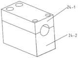
所述鞘部的一端与固定在架体上的卡扣24固定连接,另一端与滑块固定连接,所述卡扣包括第一卡扣部24-1和第二卡扣部24-2,第一卡扣部和第二卡块部内设置有用于与鞘部相匹配的半圆型槽,第一卡扣部和第二卡扣部通过螺栓固定连接,能够通过螺栓利用第一卡扣部和第二卡块部将丝鞘的鞘部端部进行压紧固定。One end of the sheath part is fixedly connected with the
本实施例中,部分由驱动轮引出的丝鞘的丝部配套设置有第一导向轮25,所述第一导向轮与架体转动连接,且与丝鞘的丝部接触,用于对丝鞘的丝部进行导向。In this embodiment, the wire portion of the wire sheath partially drawn out by the driving wheel is provided with a
本实施例中,所述滑块与支座之间设置有由柔性材质制成的丝鞘集束管26,经驱动轮引出的多个丝鞘进入丝鞘集束管内,丝鞘另一端穿出丝鞘集束管后与执行机构连接,所述丝鞘集束管用于将多个丝鞘进行集中,防止其散乱布置。In this embodiment, a wire
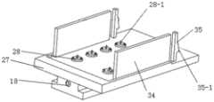
所述执行机构包括与滑块固定连接的中间箱体27,所述中间箱体内设置有十二个中间轴,中间轴与中间箱体转动连接,十二根丝鞘的丝部另一端伸入中间箱体内部并缠绕在中间轴上,丝鞘丝部的端部与中间轴固定连接,丝鞘的鞘部的该端端部与滑块固定连接。The actuator includes an
所述中间轴伸出至中间箱体外部并与从动轮28固定连接,所述从动轮及中间箱体与快换机构连接,所述快换机构用于连接末端执行元件。The intermediate shaft protrudes out of the intermediate box and is fixedly connected with the driven
所述快换机构包括外壳29,所述外壳包括顶部壳壁及固定在顶部壳壁四个边缘处的侧部壳壁,所述顶部壳壁的内侧面转动连接有多个驱动轴30,所述驱动轴与从动轮同轴设置,从动轮的端面上设置有三个卡块28-1,所述驱动轴的端部设置有三个与所述卡块相匹配的卡槽,驱动轴能够通过卡槽和卡块与从动轮卡接连接,从动轮的转动能够带动驱动轴做同步转动,所述驱动轴上缠绕有驱动线31,所述驱动线端部与驱动轴固定连接,驱动线绕接设置在顶部壳壁的第二导向轮36后平行伸出至外壳外部,多个驱动线用于连接末端执行元件。The quick-change mechanism includes a
所述外壳底部的侧部壳壁上固定有套管32,多个伸出至外壳外部的驱动线布置在套管内,套管用于对驱动线进行集线,所述滑台的底部通过螺栓可拆卸的连接有固定板33,套管穿过所述固定板,固定板用于对套管进行支撑和固定。A bushing 32 is fixed on the side wall of the bottom of the housing, and a plurality of driving wires extending out of the housing are arranged in the bushing. The bushing is used to gather the driving wires. The detached connection is provided with a fixing plate 33 through which the sleeve passes, and the fixing plate is used to support and fix the sleeve.
所述外壳与中间箱体可拆卸连接,所述中间箱体上设置有两个插板34,插板的一侧设置有由弹性塑料材质制成的卡板35,所述卡板具有三角形的卡头35-1,所述外壳与插板相对应的两个侧部壳壁上设置有第一卡槽29-1,插板能够插入第一卡槽中,第一卡槽的一侧设置有与第一卡槽端部相连通的第二卡槽29-2,第二卡槽贯穿侧部壳壁的端面设置,第一卡槽和第二卡槽能够形成一个阶梯结构29-3,卡板通过第一卡槽插入后,由于卡板为弹性塑料材质制成,第一卡槽的作用下,卡板可向插板一侧弯曲,使插板和卡板共同伸入第一卡槽内,当卡板到达第二卡槽位置时,卡板无法受到限制,回复原状,三角形的卡头与阶梯结构卡接固定,从而实现了外壳和中间箱体的固定。The outer shell is detachably connected to the middle box body, and two plug-in
所述外壳设置第二卡槽的端面上通过螺栓连接有由弹性材质支撑的压钩29-4,压钩能够在外界力的作用下对卡板施加压力,从而使卡板产生弯曲变形,使卡板能够伸入第一卡槽中,方便外壳与中间箱体的分离。A pressure hook 29-4 supported by an elastic material is connected by bolts on the end face of the casing with the second card slot. The pressure hook can exert pressure on the card plate under the action of external force, so that the card plate is bent and deformed, so that the The card board can be extended into the first card slot, so as to facilitate the separation of the outer casing and the middle box.
本实施例的电机后置的手术机器人,第一电机、第二电机、第三电机、第四电机及第五电机均与控制系统连接,接收控制系统的指令进行工作。In the surgical robot with the motor behind in this embodiment, the first motor, the second motor, the third motor, the fourth motor and the fifth motor are all connected to the control system, and receive instructions from the control system to work.
本实施例的电机后置的手术机器人,使用时,快换机构的外壳通过卡板和插板与中间箱体固定连接,且驱动轴与从动轮卡接固定,驱动线的末端连接末端执行元件,所述末端执行元件采用现有的手术执行元件即可,手术人员可根据实际需要进行选择,在此不进行详细叙述,控制系统向第一电机、第二电机及第三电机发送指令,调节末端执行元件的位置和角度,控制系统控制第四电机工作,能够控制末端执行元件进入或退出腹腔,控制系统控制第五电机工作,第五电机带动驱动轮工作,驱动轮能够对丝鞘的丝部进行收放线操作,从而带动从动轮的转动,从动轮带动驱动轴转动,驱动轴带动驱动线进行收放线工作,进而通过不同的驱动线的收放线动作带动末端执行元件的工作。In the surgical robot with the motor behind the present embodiment, when in use, the shell of the quick-change mechanism is fixedly connected to the intermediate box through the card plate and the plug-in plate, the drive shaft is fixedly connected to the driven wheel, and the end of the drive wire is connected to the end actuator. , the end effector can use the existing surgical effector, and the operator can select it according to the actual needs. It will not be described in detail here. The control system sends commands to the first motor, the second motor and the third motor to adjust the The position and angle of the end effector, the control system controls the fourth motor to work, can control the end effector to enter or exit the abdominal cavity, the control system controls the fifth motor to work, the fifth motor drives the drive wheel to work, and the drive wheel can control the wire of the wire sheath. The unit carries out the rewinding and reeling operation, thereby driving the rotation of the driven wheel, the driven wheel drives the driving shaft to rotate, and the driving shaft drives the driving line to carry out the rewinding and reeling work, and then drives the end actuator to work through the rewinding and reeling action of different driving lines.
本实施例的电机后置的手术机器人,第一电机、第二电机设置在第一连杆和第二连杆的底端,由于第一连杆和第二连杆为V型结构,所以第一电机和第二电机位于滑台的后侧,且滑台和第三电机分别设置在第一连杆和第二连杆的两侧,即第三电机也设置在手术机器人的后侧位置,则整个手术机器人的重心靠近后侧设置,避免了手术机器人头重脚轻的问题,使用时,整个手术机器人不会产生振动,准确度高,降低了手术事故发生的风险。In the surgical robot with the motor behind the present embodiment, the first motor and the second motor are arranged at the bottom ends of the first link and the second link. Since the first link and the second link are V-shaped structures, the A motor and a second motor are located on the rear side of the sliding table, and the sliding table and the third motor are respectively arranged on both sides of the first link and the second link, that is, the third motor is also arranged on the rear side of the surgical robot, Then the center of gravity of the entire surgical robot is set close to the rear side, which avoids the problem of the surgical robot being top-heavy. When in use, the entire surgical robot will not vibrate, with high accuracy and reducing the risk of surgical accidents.
且本实施例驱动线机构通过丝鞘带动执行机构动作,丝鞘的累计误差小,动作精度更高。In addition, in this embodiment, the drive wire mechanism drives the actuator to act through the wire sheath, the cumulative error of the wire sheath is small, and the action accuracy is higher.
上述虽然结合附图对本发明的具体实施方式进行了描述,但并非对本发明保护范围的限制,所属领域技术人员应该明白,在本发明的技术方案的基础上,本领域技术人员不需要付出创造性劳动即可做出的各种修改或变形仍在本发明的保护范围以内。Although the specific embodiments of the present invention have been described above in conjunction with the accompanying drawings, they do not limit the scope of protection of the present invention. Those skilled in the art should understand that on the basis of the technical solutions of the present invention, those skilled in the art do not need to pay creative work. Various modifications or deformations that can be made are still within the protection scope of the present invention.
Claims (10)
Priority Applications (1)
| Application Number | Priority Date | Filing Date | Title |
|---|---|---|---|
| CN201911001627.8ACN110711032B (en) | 2019-10-21 | 2019-10-21 | A miniaturized surgical robot with a rear motor |
Applications Claiming Priority (1)
| Application Number | Priority Date | Filing Date | Title |
|---|---|---|---|
| CN201911001627.8ACN110711032B (en) | 2019-10-21 | 2019-10-21 | A miniaturized surgical robot with a rear motor |
Publications (2)
| Publication Number | Publication Date |
|---|---|
| CN110711032Atrue CN110711032A (en) | 2020-01-21 |
| CN110711032B CN110711032B (en) | 2020-08-25 |
Family
ID=69213003
Family Applications (1)
| Application Number | Title | Priority Date | Filing Date |
|---|---|---|---|
| CN201911001627.8AActiveCN110711032B (en) | 2019-10-21 | 2019-10-21 | A miniaturized surgical robot with a rear motor |
Country Status (1)
| Country | Link |
|---|---|
| CN (1) | CN110711032B (en) |
Cited By (3)
| Publication number | Priority date | Publication date | Assignee | Title |
|---|---|---|---|---|
| CN112536789A (en)* | 2020-12-02 | 2021-03-23 | 山东大学 | Rigid-flexible combined type outer limb mechanical arm and auxiliary operation device thereof |
| CN113288432A (en)* | 2021-05-17 | 2021-08-24 | 杭州电子科技大学 | Minimally invasive surgery manipulator capable of replacing scalpel |
| WO2023136153A1 (en)* | 2022-01-14 | 2023-07-20 | キヤノン株式会社 | Continuum robot system |
Citations (7)
| Publication number | Priority date | Publication date | Assignee | Title |
|---|---|---|---|---|
| CN102697564A (en)* | 2012-06-20 | 2012-10-03 | 哈尔滨工业大学 | Flexible-arm robot for single-pore laparoscopic minimally-invasive operation |
| US20130244820A1 (en)* | 2004-09-30 | 2013-09-19 | Intuitive Surgical Operations, Inc. | [[Multi-Ply]] Strap guide system and methods thereof for robotic surgical arms Drive Trains for Robotic Arms |
| CN206630633U (en)* | 2017-01-04 | 2017-11-14 | 山东大学齐鲁医院 | One kind is used for minimally invasive surgical operation robot quick-changing mechanism |
| CN107693120A (en)* | 2017-09-11 | 2018-02-16 | 山东科技大学 | A kind of operated eye robot |
| CN109091236A (en)* | 2017-06-21 | 2018-12-28 | 山东威高手术机器人有限公司 | A kind of Minimally Invasive Surgery instrument auxiliary operation arm |
| CN208851537U (en)* | 2018-03-16 | 2019-05-14 | 上海形状记忆合金材料有限公司 | An adjustable bendable delivery sheath capable of displaying the bending angle |
| CN209285720U (en)* | 2018-11-13 | 2019-08-23 | 重庆金山医疗机器人有限公司 | Band driving wheel fixation with steel wire structure and surgical operation auxiliary robot device system |
- 2019
- 2019-10-21CNCN201911001627.8Apatent/CN110711032B/enactiveActive
Patent Citations (7)
| Publication number | Priority date | Publication date | Assignee | Title |
|---|---|---|---|---|
| US20130244820A1 (en)* | 2004-09-30 | 2013-09-19 | Intuitive Surgical Operations, Inc. | [[Multi-Ply]] Strap guide system and methods thereof for robotic surgical arms Drive Trains for Robotic Arms |
| CN102697564A (en)* | 2012-06-20 | 2012-10-03 | 哈尔滨工业大学 | Flexible-arm robot for single-pore laparoscopic minimally-invasive operation |
| CN206630633U (en)* | 2017-01-04 | 2017-11-14 | 山东大学齐鲁医院 | One kind is used for minimally invasive surgical operation robot quick-changing mechanism |
| CN109091236A (en)* | 2017-06-21 | 2018-12-28 | 山东威高手术机器人有限公司 | A kind of Minimally Invasive Surgery instrument auxiliary operation arm |
| CN107693120A (en)* | 2017-09-11 | 2018-02-16 | 山东科技大学 | A kind of operated eye robot |
| CN208851537U (en)* | 2018-03-16 | 2019-05-14 | 上海形状记忆合金材料有限公司 | An adjustable bendable delivery sheath capable of displaying the bending angle |
| CN209285720U (en)* | 2018-11-13 | 2019-08-23 | 重庆金山医疗机器人有限公司 | Band driving wheel fixation with steel wire structure and surgical operation auxiliary robot device system |
Cited By (3)
| Publication number | Priority date | Publication date | Assignee | Title |
|---|---|---|---|---|
| CN112536789A (en)* | 2020-12-02 | 2021-03-23 | 山东大学 | Rigid-flexible combined type outer limb mechanical arm and auxiliary operation device thereof |
| CN113288432A (en)* | 2021-05-17 | 2021-08-24 | 杭州电子科技大学 | Minimally invasive surgery manipulator capable of replacing scalpel |
| WO2023136153A1 (en)* | 2022-01-14 | 2023-07-20 | キヤノン株式会社 | Continuum robot system |
Also Published As
| Publication number | Publication date |
|---|---|
| CN110711032B (en) | 2020-08-25 |
Similar Documents
| Publication | Publication Date | Title |
|---|---|---|
| CN110711032B (en) | A miniaturized surgical robot with a rear motor | |
| EP3903715A1 (en) | Flexible surgical tool system | |
| EP3903711B1 (en) | Double-curved flexible surgical tool system | |
| WO2021184791A1 (en) | Serpentine surgical robot applied to minimally invasive surgery | |
| CN107080588A (en) | A kind of new micro-wound operation robot control device driven by line | |
| CN210354899U (en) | Medical surgical robot | |
| CN113040917B (en) | Concentric tube surgical robot for natural orifice | |
| EP4316403B1 (en) | Rear-end transmission apparatus, medical instrument and surgical robot | |
| CN107981932A (en) | A kind of urological surgery robot arm | |
| CN109009453A (en) | Intervene the force feedback type main manipulator of robot | |
| CN113040918B (en) | A surgical robot for the removal of bone lesions in confined spaces | |
| WO2023160486A1 (en) | End articulated arm, robotic arm, and medical cart | |
| CN113229935B (en) | A flexible robotic arm and endoscope locked by a driving wire | |
| CN211049592U (en) | A robotic device for single-port minimally invasive surgery | |
| CN219070434U (en) | Instrument transmission device, surgical instrument and surgical robot | |
| CN114668503A (en) | Diagnosis and treatment integrated surgical robot | |
| CN114948234A (en) | Robot for vascular intervention operation | |
| CN220213036U (en) | Pneumology thorax puncture positioning device | |
| CN117731402A (en) | General suspension arm system of interventional robot | |
| CN209611304U (en) | A kind of integral layout structure of the single hole operating robot with running fix joint | |
| CN114903599A (en) | Fixed point mechanism, mechanical arm and surgical robot | |
| CN115721413A (en) | Eight-degree-of-freedom minimally invasive surgery robot | |
| CN115919377A (en) | Biopsy accessories, biopsy devices, biopsy device mobile devices and biopsy systems | |
| CN108433812A (en) | A kind of integral layout structure of the single hole operating robot with running fix joint | |
| CN113974843A (en) | Active three-freedom-degree surgical instrument |
Legal Events
| Date | Code | Title | Description |
|---|---|---|---|
| PB01 | Publication | ||
| PB01 | Publication | ||
| SE01 | Entry into force of request for substantive examination | ||
| SE01 | Entry into force of request for substantive examination | ||
| GR01 | Patent grant | ||
| GR01 | Patent grant |