CN110710718A - an electronic cigarette - Google Patents
an electronic cigaretteDownload PDFInfo
- Publication number
- CN110710718A CN110710718ACN201911144233.8ACN201911144233ACN110710718ACN 110710718 ACN110710718 ACN 110710718ACN 201911144233 ACN201911144233 ACN 201911144233ACN 110710718 ACN110710718 ACN 110710718A
- Authority
- CN
- China
- Prior art keywords
- oil
- hole
- electronic cigarette
- outlet
- shell
- Prior art date
- Legal status (The legal status is an assumption and is not a legal conclusion. Google has not performed a legal analysis and makes no representation as to the accuracy of the status listed.)
- Granted
Links
- 239000003571electronic cigaretteSubstances0.000titleclaimsabstractdescription71
- 239000000779smokeSubstances0.000claimsabstractdescription28
- 238000009434installationMethods0.000claimsabstractdescription23
- 238000000889atomisationMethods0.000claimsabstractdescription18
- 239000012530fluidSubstances0.000claimsabstractdescription10
- 241000208125NicotianaSpecies0.000claimsabstract6
- 235000002637Nicotiana tabacumNutrition0.000claimsabstract6
- 239000007788liquidSubstances0.000claimsdescription71
- 238000003860storageMethods0.000claimsdescription34
- 239000012528membraneSubstances0.000claimsdescription33
- 238000010438heat treatmentMethods0.000claimsdescription30
- 239000002184metalSubstances0.000claimsdescription28
- 239000011888foilSubstances0.000claimsdescription23
- 230000002093peripheral effectEffects0.000claimsdescription10
- 230000000149penetrating effectEffects0.000claims1
- 238000009826distributionMethods0.000abstractdescription18
- 238000007789sealingMethods0.000description43
- 238000010586diagramMethods0.000description12
- 238000000034methodMethods0.000description11
- 230000008569processEffects0.000description10
- 238000002347injectionMethods0.000description7
- 239000007924injectionSubstances0.000description7
- 238000003825pressingMethods0.000description6
- 229920000742CottonPolymers0.000description5
- 238000004891communicationMethods0.000description5
- 239000000463materialSubstances0.000description5
- 238000004804windingMethods0.000description5
- 230000008859changeEffects0.000description4
- 239000000443aerosolSubstances0.000description3
- 239000000919ceramicSubstances0.000description3
- 238000000926separation methodMethods0.000description3
- 230000000391smoking effectEffects0.000description3
- 230000009471actionEffects0.000description2
- 230000000670limiting effectEffects0.000description2
- 238000004519manufacturing processMethods0.000description2
- 238000012545processingMethods0.000description2
- 238000012546transferMethods0.000description2
- 238000003466weldingMethods0.000description2
- 238000009825accumulationMethods0.000description1
- 230000004075alterationEffects0.000description1
- 230000009286beneficial effectEffects0.000description1
- 230000008901benefitEffects0.000description1
- 239000002775capsuleSubstances0.000description1
- 235000019504cigarettesNutrition0.000description1
- 238000002485combustion reactionMethods0.000description1
- 230000000694effectsEffects0.000description1
- 230000008713feedback mechanismEffects0.000description1
- 230000006870functionEffects0.000description1
- 239000003365glass fiberSubstances0.000description1
- 230000036541healthEffects0.000description1
- 239000003779heat-resistant materialSubstances0.000description1
- 230000003993interactionEffects0.000description1
- 239000003595mistSubstances0.000description1
- 230000004048modificationEffects0.000description1
- 238000012986modificationMethods0.000description1
- 238000005381potential energyMethods0.000description1
- 230000004044responseEffects0.000description1
- 238000004904shorteningMethods0.000description1
- 239000007921spraySubstances0.000description1
- 238000006467substitution reactionMethods0.000description1
Images


Landscapes
- Fats And Perfumes (AREA)
- Disinfection, Sterilisation Or Deodorisation Of Air (AREA)
Abstract
Description
Translated fromChinese技术领域technical field
本发明涉及电子烟技术领域,尤其是涉及一种电子烟。The invention relates to the technical field of electronic cigarettes, in particular to an electronic cigarette.
背景技术Background technique
目前电子烟多使用微孔陶瓷雾化芯和导油棉芯缠绕金属发热丝的形式,微孔陶瓷雾化芯在供油时存在油口位置供油充分而周边位置供油不足,导致油液分布与热量分布不匹配所引起的干烧和漏油;导油棉芯缠绕金属发热丝形式的雾化器利用毛细现象导油,随着储油装置油液液面的变化引起的供油分布与热量分布不匹配,也会出现干烧和漏油,对抽吸者的健康有极大的危害。At present, electronic cigarettes mostly use the form of microporous ceramic atomizing core and oil-guiding cotton core wound with metal heating wire. When the microporous ceramic atomizing core is supplied with oil, there is sufficient oil supply at the oil port position and insufficient oil supply at the surrounding positions, resulting in oil supply. Dry burning and oil leakage caused by the mismatch between the distribution and the heat distribution; the atomizer in the form of a metal heating wire wrapped with an oil guide cotton core uses the capillary phenomenon to guide oil, and the oil supply distribution caused by the change of the oil level of the oil storage device If it does not match the heat distribution, dry burning and oil leakage will also occur, which is extremely harmful to the health of the smoker.
如公开号为CN109805459A的中国申请公开了一种主动供油式的雾化结构,所用的雾化器为陶瓷雾化器,即便供油为微型液泵主动式供油,但由于导入雾化器的油从中心进入雾化器,这会造成雾化器中心部分供油充分而周边部分相对供油不足,使得热量与油液分布不匹配造成局部干烧的现象。For example, the Chinese application with publication number CN109805459A discloses an active oil supply type atomization structure, and the atomizer used is a ceramic atomizer. The oil enters the atomizer from the center, which will cause sufficient oil supply in the center part of the atomizer and insufficient oil supply in the peripheral part, causing the heat and oil distribution to not match, resulting in local dry burning.
又如公开号为CN109259325A的中国申请公开了一种电子烟雾化器的结构,并具体公开了一种用多根细管固定在一起的细管束插入烟油腔,利用形成的毛细间隙的方式来导油的结构,会使得由于烟油的消耗影响导油速度的变化,当液面较低的时候导油不及时会引起干烧。Another example is the Chinese application with publication number CN109259325A, which discloses the structure of an electronic cigarette atomizer, and specifically discloses a thin tube bundle fixed together with a plurality of thin tubes inserted into the smoke oil cavity, and the formed capillary gap is used to The structure of the oil guide will affect the change of the oil guide speed due to the consumption of the e-liquid. When the liquid level is low, the oil will not be guided in time, which will cause dry burning.
发明内容SUMMARY OF THE INVENTION
本发明提出了一种电子烟,所述电子烟所述电子烟通过输油管使得油液分布与热量分布相匹配,解决电子烟漏油与干烧问题。The present invention provides an electronic cigarette. The electronic cigarette uses an oil pipe to match the oil distribution with the heat distribution, so as to solve the problems of oil leakage and dry burning of the electronic cigarette.
根据本发明实施例的电子烟,包括:外壳,所述外壳的两端敞开,所述外壳的侧壁上具有第一进气孔;吸嘴,所述吸嘴设在所述外壳的一端,所述吸嘴具有出烟孔;烟油仓,所述烟油仓设在所述外壳内,所述烟油仓具有间隔开的烟道和储油腔,所述烟道的一端与所述出烟孔连通,所述烟油仓的底部具有与所述储油腔连通的第一输油孔,所述烟油仓的顶部具有与所述储油腔连通的注油孔,所述储油腔与所述第一进气孔相对的一侧具有敞开口;柔性膜,所述柔性膜封堵所述敞开口,所述柔性膜与所述储油仓限定出柔性油囊;安装底座,所述安装底座设在所述外壳的另一端,所述烟油仓的一端与所述安装底座连接,所述安装底座与所述外壳、所述吸嘴以及所述烟油仓限定出与所述烟道连通的雾化室,所述安装底座具有进油道,所述进油道的一端具有与所述第一输油孔相对的第二输油孔,所述第二输油孔与所述第一输油孔连通,所述进油道的另一端具有进油孔,所述安装底座上还具有出油道,所述出油道与所述进油道间隔开,所述出油道的一端具有出油孔,所述出油道的另一端具有导油孔,所述安装底座上的底壁上设有与所述雾化室连通的第二进气孔;微型泵,所述微型泵固定在所述安装底座上,所述微型泵具有与泵腔连通的进流质口和出流质口,所述进流质口与所述进油孔连通,所述出流质口与所述出油孔连通;用于对烟油进行雾化处理的雾化芯组件,所述雾化芯组件设在所述雾化室内,且所述雾化芯组件固定在所述安装底座上。An electronic cigarette according to an embodiment of the present invention includes: a casing, both ends of the casing are open, and a side wall of the casing is provided with a first air intake hole; a suction nozzle is provided at one end of the casing, The suction nozzle has a smoke outlet; the smoke oil tank is arranged in the outer casing, and the smoke oil tank has a spaced flue and an oil storage cavity, and one end of the flue is connected to the The smoke outlet hole is connected, the bottom of the smoke oil bin has a first oil delivery hole that communicates with the oil storage cavity, the top of the smoke oil bin has an oil injection hole that communicates with the oil storage cavity, and the oil storage cavity The side of the cavity opposite to the first air inlet has an opening; a flexible membrane, the flexible membrane blocks the opening, and the flexible membrane and the oil storage tank define a flexible oil bag; an installation base, The mounting base is provided at the other end of the housing, one end of the e-liquid bin is connected to the mounting base, and the mounting base and the housing, the suction nozzle and the e-liquid bin define a connection with the e-liquid bin. The atomization chamber communicated with the flue, the installation base has an oil inlet, one end of the oil inlet has a second oil hole opposite to the first oil hole, and the second oil hole is connected to the first oil hole. The first oil delivery hole is connected, the other end of the oil inlet channel has an oil inlet hole, and the installation base also has an oil outlet channel, the oil outlet channel is spaced from the oil inlet channel, and the oil outlet channel is spaced apart from the oil inlet channel. One end of the oil passage is provided with an oil outlet hole, the other end of the oil outlet is provided with an oil guide hole, and the bottom wall on the mounting base is provided with a second air inlet hole communicating with the atomizing chamber; the micro pump, The micro-pump is fixed on the mounting base, and the micro-pump has an inflow mass port and an outflow mass port that communicate with the pump cavity, the inflow mass port is communicated with the oil inlet hole, and the outflow mass port is connected to the The oil outlet holes are connected; the atomization core assembly is used for atomizing the e-liquid, the atomization core assembly is arranged in the atomization chamber, and the atomization core assembly is fixed on the installation base.
根据本发明实施例的电子烟,通过输油管使得油液分布与热量分布相匹配,解决电子烟漏油与干烧问题,此外,烟道和柔性油囊布置到一个烟油仓上,且烟道和柔性油囊隔离,实现烟油和烟道的分离,进一步防止抽吸过程中烟油被吸入嘴中,从而可以提升用户的使用体验。According to the electronic cigarette of the embodiment of the present invention, the oil distribution is matched with the heat distribution through the oil pipe, and the problems of oil leakage and dry burning of the electronic cigarette are solved. It is isolated from the flexible oil bag to realize the separation of the e-liquid and the flue, and further prevent the e-liquid from being sucked into the mouth during the smoking process, thereby improving the user experience.
根据本发明的一些实施例,在所述柔性油囊内未加注烟油时,所述柔性膜与所述储油腔的底壁贴合,在所述柔性油囊内注满烟油时,所述柔性油囊与所述所述外壳的内壁止抵。According to some embodiments of the present invention, when the flexible oil bag is not filled with e-liquid, the flexible film is attached to the bottom wall of the oil storage cavity, and when the flexible oil bag is filled with e-liquid , the flexible oil bag stops against the inner wall of the shell.
根据本发明的一些实施例,所述微型泵的侧壁上设有两个间隔开的电极,所述安装底座的底壁上设有两个间隔开的电极柱孔,每个所述电极柱孔内均设有电极柱,所述电子烟还包括两个金属导电箔片,两个所述金属导电箔片与两个电极、两个电极柱一一对应配合,所述金属导电箔片包括:第一连接段,所述第一连接段的一侧与所述电极止抵,所述第一连接段的另一侧与所述外壳的内壁止抵;第二连接段,所述第二连接段与所述第一连接段连接,所述第二连接段的一侧与所述电极柱止抵,所述第二连接段的延伸方向与所述第一连接段的延伸方向垂直。According to some embodiments of the present invention, the side wall of the micro pump is provided with two spaced electrodes, the bottom wall of the mounting base is provided with two spaced electrode post holes, each of the electrode posts Electrode posts are arranged in the holes, and the electronic cigarette further includes two metal conductive foils, and the two metal conductive foils are matched with the two electrodes and the two electrode posts in a one-to-one correspondence, and the metal conductive foils include : the first connection segment, one side of the first connection segment is in contact with the electrode, and the other side of the first connection segment is in contact with the inner wall of the housing; the second connection segment, the second The connecting section is connected with the first connecting section, one side of the second connecting section is abutted against the electrode column, and the extending direction of the second connecting section is perpendicular to the extending direction of the first connecting section.
根据本发明的一些实施例,所述雾化芯组件包括:输油管,所述输油管的一端具有与所述导油孔连通第三输油孔,所述输油管的另一端封闭,所述输油管的周壁上具有在所述输油管的厚度方向上贯穿所述输油管的开口,所述开口沿所述输油管的轴向方向延伸;导油套管,所述导油套管套设在所述输油管上,且所述导油套管包裹所述开口;发热丝,所述发热丝缠绕在所述导油套管的外周壁上。According to some embodiments of the present invention, the atomizing core assembly includes: an oil delivery pipe, one end of the oil delivery pipe has a third oil delivery hole that communicates with the oil guide hole, the other end of the oil delivery pipe is closed, and a peripheral wall of the oil delivery pipe is There is an opening passing through the oil pipeline in the thickness direction of the oil pipeline, and the opening extends along the axial direction of the oil pipeline; an oil guide sleeve, the oil guide sleeve is sleeved on the oil pipeline, and The oil guiding sleeve wraps the opening; and the heating wire is wound on the outer peripheral wall of the oil guiding sleeve.
根据本发明的一些实施例,所述输油管上的开口为狭缝状,狭缝宽度为0.01-2.1mm。According to some embodiments of the present invention, the opening on the oil pipeline is in the shape of a slit, and the width of the slit is 0.01-2.1 mm.
根据本发明的一些实施例,所述开口为一个或多个,多个开口在所述输油管的周向方向间隔设置。According to some embodiments of the present invention, the openings are one or more, and the plurality of openings are arranged at intervals in the circumferential direction of the oil pipeline.
根据本发明的一些实施例,所述输油管的封闭端设有连通所述开口的排气口。According to some embodiments of the present invention, the closed end of the oil delivery pipe is provided with an exhaust port communicating with the opening.
根据本发明的一些实施例,所述输油管的朝向所述排气口的端面上设有半透膜,所述半透膜覆盖在所述排气口上,且所述半透膜允许气体通过而不允许液体通过。According to some embodiments of the present invention, a semi-permeable membrane is provided on the end face of the oil pipeline facing the exhaust port, the semi-permeable membrane covers the exhaust port, and the semi-permeable membrane allows gas to pass through without Liquids are not allowed to pass through.
根据本发明的一些实施例,所述排气口为多个,所述半透膜的形状与所述输油管的截面形状相同,且所述半透膜的外周沿与所述输油管端面的外周沿相连。According to some embodiments of the present invention, there are multiple exhaust ports, the shape of the semi-permeable membrane is the same as the cross-sectional shape of the oil pipeline, and the outer periphery of the semi-permeable membrane is the same as the outer periphery of the end face of the oil pipeline. connected.
本发明的附加方面和优点将在下面的描述中部分给出,部分将从下面的描述中变得明显,或通过本发明的实践了解到。Additional aspects and advantages of the present invention will be set forth, in part, from the following description, and in part will be apparent from the following description, or may be learned by practice of the invention.
附图说明Description of drawings
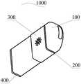
图1是根据本发明实施例的电子烟的结构示意图;1 is a schematic structural diagram of an electronic cigarette according to an embodiment of the present invention;
图2是根据本发明实施例的电子烟的剖视图;2 is a cross-sectional view of an electronic cigarette according to an embodiment of the present invention;
图3是根据本发明实施例的电子烟的吸嘴的结构示意图;3 is a schematic structural diagram of a mouthpiece of an electronic cigarette according to an embodiment of the present invention;
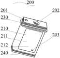
图4是根据本发明实施例的电子烟的烟油仓的立体图;4 is a perspective view of an e-liquid tank of an electronic cigarette according to an embodiment of the present invention;
图5是根据本发明实施例的电子烟的烟油仓的另一个方向的立体图;5 is a perspective view of the e-liquid tank of the electronic cigarette in another direction according to an embodiment of the present invention;
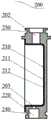
图6是根据本发明实施例的电子烟的烟油仓的剖视图,其中柔性油囊处于未注油状态;6 is a cross-sectional view of an e-cigarette oil tank of an electronic cigarette according to an embodiment of the present invention, wherein the flexible oil bag is in an unfilled state;
图7是根据本发明实施例的电子烟的烟油仓的剖视图,其中柔性油囊处于注油状态;7 is a cross-sectional view of an e-cigarette oil tank of an electronic cigarette according to an embodiment of the present invention, wherein the flexible oil bag is in an oil filling state;
图8是根据本发明实施例的电子烟的外壳的结构示意图;8 is a schematic structural diagram of a casing of an electronic cigarette according to an embodiment of the present invention;
图9是根据本发明实施例的电子烟的安装底座的结构示意图;9 is a schematic structural diagram of a mounting base of an electronic cigarette according to an embodiment of the present invention;
图10是根据本发明实施例的电子烟的安装底座的剖视图;10 is a cross-sectional view of a mounting base of an electronic cigarette according to an embodiment of the present invention;
图11是根据本发明实施例的电子烟的安装底座和微型泵的结构示意图;11 is a schematic structural diagram of a mounting base and a micro pump of an electronic cigarette according to an embodiment of the present invention;
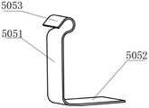
图12是根据本发明实施例的电子烟的金属导电箔片的结构示意图;12 is a schematic structural diagram of a metal conductive foil of an electronic cigarette according to an embodiment of the present invention;
图13是根据本发明实施例的电子烟的雾化芯组件的结构示意图;13 is a schematic structural diagram of an atomizing core assembly of an electronic cigarette according to an embodiment of the present invention;
图14是根据本发明一个实施例的电子烟的输油管的结构示意图;14 is a schematic structural diagram of an oil delivery pipe of an electronic cigarette according to an embodiment of the present invention;
图15是根据本发明实施例的电子烟的微型泵的吸流状态图;Fig. 15 is a state diagram of suction flow of a micro-pump of an electronic cigarette according to an embodiment of the present invention;
图16是根据本发明实施例的电子烟的微型泵的排流状态图;Fig. 16 is a flow state diagram of a micro-pump of an electronic cigarette according to an embodiment of the present invention;
图17是根据本发明另一个实施例的输油管的结构示意图;17 is a schematic structural diagram of an oil pipeline according to another embodiment of the present invention;
图18是图17中结构的剖视图;Figure 18 is a cross-sectional view of the structure in Figure 17;
图19是沿图18中A-A线的剖视图;Figure 19 is a sectional view taken along line A-A in Figure 18;
图20是根据本发明又一个实施例的输油管的结构示意图;20 is a schematic structural diagram of an oil pipeline according to yet another embodiment of the present invention;
图21是图20中结构的剖视图。FIG. 21 is a cross-sectional view of the structure of FIG. 20 .
附图标记:Reference number:
1000:电子烟,1000: electronic cigarette,
100:吸嘴,101:出烟孔,100: suction nozzle, 101: smoke outlet,
200:烟油仓,201:烟道,202:注油孔,203:第一输油孔,200: e-juice tank, 201: flue, 202: oil filling hole, 203: first oil delivery hole,
210:柔性油囊,211:储油腔,212:柔性膜,210: flexible oil bladder, 211: oil storage chamber, 212: flexible membrane,
220:限位连接槽,230:第一密封沟槽,231:第一密封圈,220: Limit connection groove, 230: First sealing groove, 231: First sealing ring,
240:第二密封沟槽,241:第二密封圈,250:密封堵头,240: Second sealing groove, 241: Second sealing ring, 250: Sealing plug,
300:外壳,301:第一进气孔,300: shell, 301: first air intake,
400:安装底座,410:微型液泵安装面,411:进油孔,400: Mounting base, 410: Micro liquid pump mounting surface, 411: Oil inlet hole,
412:出油孔,413:环形沟槽,414:定位凸缘,415:下限位面槽口,412: oil outlet hole, 413: annular groove, 414: positioning flange, 415: lower limit surface notch,
420:雾化芯安装面,421:导油孔,430:定位凸台,431:第二输油孔,420: Atomizer core mounting surface, 421: Oil guide hole, 430: Positioning boss, 431: Second oil hole,
440:电极柱孔,450:第二进气孔,460:进油道,470:出油道,440: Electrode column hole, 450: Second air inlet, 460: Oil inlet, 470: Oil outlet,
480:第三密封沟槽,481:底部密封圈,490:第三密封圈,480: Third seal groove, 481: Bottom seal, 490: Third seal,
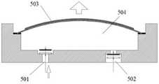
500:微型泵,501:进流质口,502:出流质口,503:振子,500: Micro pump, 501: Inlet mass port, 502: Outflow mass port, 503: Vibrator,
504:泵腔,505:金属导电箔片,5051:第一连接段,504: Pump chamber, 505: Metal conductive foil, 5051: First connecting segment,
5052:第二连接段,5053:压靠面,5052: Second connecting segment, 5053: Pressing surface,
506:电极柱,600:雾化室,506: Electrode column, 600: Spray chamber,
700:雾化芯组件,710:输油管,711:第三输油孔,700: Atomizer core assembly, 710: Oil pipe, 711: Third oil hole,
712:封口端,713:开口,720:导油套管,730:发热丝,740:Ⅱ型电极柱;750:排气口,760:半透膜。712: sealing end, 713: opening, 720: oil guiding sleeve, 730: heating wire, 740: type II electrode column; 750: exhaust port, 760: semi-permeable membrane.
具体实施方式Detailed ways
下面详细描述本发明的实施例,所述实施例的示例在附图中示出,其中自始至终相同或类似的标号表示相同或类似的元件或具有相同或类似功能的元件。下面通过参考附图描述的实施例是示例性的,旨在用于解释本发明,而不能理解为对本发明的限制。The following describes in detail the embodiments of the present invention, examples of which are illustrated in the accompanying drawings, wherein the same or similar reference numerals refer to the same or similar elements or elements having the same or similar functions throughout. The embodiments described below with reference to the accompanying drawings are exemplary, and are intended to explain the present invention and should not be construed as limiting the present invention.
下文的公开提供了许多不同的实施例或例子用来实现本发明的不同结构。为了简化本发明的公开,下文中对特定例子的部件和设置进行描述。当然,它们仅仅为示例,并且目的不在于限制本发明。此外,本发明可以在不同例子中重复参考数字和/或字母。这种重复是为了简化和清楚的目的,其本身不指示所讨论各种实施例和/或设置之间的关系。此外,本发明提供了的各种特定的工艺和材料的例子,但是本领域普通技术人员可以意识到其他工艺的可应用于性和/或其他材料的使用。The following disclosure provides many different embodiments or examples for implementing different structures of the invention. In order to simplify the disclosure of the present invention, the components and arrangements of specific examples are described below. Of course, they are only examples and are not intended to limit the invention. Furthermore, the present invention may repeat reference numerals and/or letters in different instances. This repetition is for the purpose of simplicity and clarity and does not in itself indicate a relationship between the various embodiments and/or arrangements discussed. In addition, the present disclosure provides examples of various specific processes and materials, but one of ordinary skill in the art will recognize the applicability of other processes and/or the use of other materials.
下面参考图1-图21描述根据本发明实施例的电子烟1000。The
如图1、图2、图4、图9和图13所示,根据本发明实施例的电子烟1000,包括:外壳300、吸嘴100、烟油仓200、柔性膜212、安装底座400、微型泵500和用于对烟油进行雾化处理的雾化芯组件700。As shown in FIG. 1 , FIG. 2 , FIG. 4 , FIG. 9 and FIG. 13 , an
具体地,如图8所示,外壳300的两端敞开,外壳300的侧壁上具有第一进气孔301,吸嘴100设在外壳300的一端,吸嘴100具有出烟孔101。可以理解的是,当用户通过出烟孔101吸烟时,外部的空气可以通过第一进气孔301进入外壳300内,使得烟油可以顺利排出。由此,可以避免内外压差过大,造成烟头无法流出。Specifically, as shown in FIG. 8 , both ends of the
如图2-图7所示,烟油仓200设在外壳300内,烟油仓200具有间隔开的烟道201和储油腔211,烟道201的一端与出烟孔101连通,烟油仓200的底部具有与储油腔211连通的第一输油孔203,烟油仓200的顶部具有与储油腔211连通的注油孔202,储油腔211与第一进气孔301相对的一侧具有敞开口,柔性膜212封堵敞开口,柔性膜212与储油仓限定出柔性油囊210。As shown in FIG. 2-FIG. 7, the
可以理解的是,烟道201和柔性油囊210布置到一个烟油仓200上,且烟道201和柔性油囊210隔离,在保证结构紧凑型的同时实现了烟油和烟道201的分离,进一步防止抽吸过程中烟油被吸入嘴中,从而可以提升用户的使用体验。It can be understood that, the
如图2和图9-图11所示,安装底座400设在外壳300的另一端,烟油仓200的一端与安装底座400连接,安装底座400与外壳300、吸嘴100以及烟油仓200限定出与烟道201连通的雾化室600,安装底座400具有进油道460,进油道460的一端具有与第一输油孔203相对的第二输油孔431,第二输油孔431和第一输油孔203与进油道460连通,进油道460的另一端具有进油孔411,安装底座400上还具有出油道470,出油道470与进油道460间隔开,出油道470的一端具有出油孔412,出油道470的另一端具有导油孔421,安装底座400上的底壁上设有与雾化室600连通的第二进气孔450,微型泵500固定在安装底座400上,微型泵500具有与泵腔504连通的进流质口501和出流质口502,进流质口501与进油孔411连通,出流质口502与出油孔412连通,雾化芯组件700设在雾化室600内,且雾化芯组件700固定在安装底座400上。As shown in FIGS. 2 and 9 to 11 , the mounting
可以理解的是,当外部的空气通过第一进气孔301进入外壳300内挤压柔性模时,柔性膜212挤压柔性油囊210内的烟油从第一输油孔203流出柔性油囊210,并通过第二输油孔431进入进油道460,并在微型泵500的控制下依次通过进油孔411和进流质口501进入泵腔504,然后通过出流质口502和出油孔412进入出油道470,最后通过导油孔421排出。It can be understood that when the external air enters the
其中,进油道460和出油道470均设置在安装底座400上,可以提升减少微型泵500与雾化芯组件700之间的间距,从而缩短流道的长度,进一步提升了电子烟1000内部结构的紧凑型,有利于减少电子烟1000的外形尺寸,而且零部件较少,加工制造难度,从而可以减少电子烟1000的加工成本。The oil inlet channel 460 and the oil outlet channel 470 are both arranged on the mounting
根据本发明实施例的电子烟1000,通过将烟油仓200、微型泵500、雾化芯组件700、进油道460和出油道470均设置在安装底座400上,可以提升电子烟1000内部结构的紧凑性,有利于减少电子烟1000的外形尺寸,而且零部件较少,加工制造难度,从而可以减少电子烟1000的加工成本。此外,烟道201和柔性油囊210布置到一个烟油仓200上,且烟道201和柔性油囊210隔离,实现烟油和烟道201的分离,进一步防止抽吸过程中烟油被吸入嘴中,从而可以提升用户的使用体验。According to the
根据本发明的一些实施例,如图2和图4所示,烟油仓200的靠近吸嘴100的一端具有第一密封沟槽230,第一密封沟槽230内设有第一密封圈231,烟油仓200与吸嘴100通过第一密封圈231密封连接。由此,可以实现烟油仓200与吸嘴100之间的密封,从而避免从第一进气孔301进入外壳300内的气流朝向吸嘴100泄漏,进而保证用户从出烟孔101吸入的是烟气。According to some embodiments of the present invention, as shown in FIG. 2 and FIG. 4 , one end of the
根据本发明的一些实施例,如图2和图4所示,烟油仓200的靠近安装底座400的一端具有第二密封沟槽240,第二密封沟槽240内设有第二密封圈241,烟油仓200与外壳300通过第二密封圈241密封连接。可以理解的是,第一进气孔301连通外部空气和烟油仓200构成第一气道,微型泵500连通柔性油囊210和雾化芯组件700,第二进气孔450连通雾化室600、烟道201和出烟孔101,构成第二气道,第二密封圈241将第一气道和第二气道隔绝开,第一气道始终保持着烟油仓200内的气压与外界空气压力的平衡,保证电子烟1000在使用时,烟油能够连续稳定进入泵腔504,电子烟1000在不使用时,不会因为外界气压变化而形成漏油,抽吸过程中,柔性油囊210内的烟油经微型泵500压力输送至雾化芯组件700发热雾化,雾化室600内形成负压,空气在负压作用下进入雾化室600,将烟油雾化产生的气溶胶沿着第二气道送入口中。According to some embodiments of the present invention, as shown in FIGS. 2 and 4 , one end of the
根据本发明的一些实施例,如图5和图9所示,安装底座400的顶壁上设有定位凸台430,烟油仓200的底壁上设有与定位凸台430对应配合的限位连接槽220。可以理解的是,定位凸台430和限位连接槽220对安装底座400与烟油仓200之间的连接具有限位作用,由此不仅可以提升安装底座400与烟油仓200的装配效率,还可以提升安装底座400与烟油仓200的安装精度。According to some embodiments of the present invention, as shown in FIG. 5 and FIG. 9 , the top wall of the
根据本发明的一些实施例,如图6和图7所示,在柔性油囊210内未加注烟油时,柔性膜212与储油腔211的底壁贴合,在柔性油囊210内注满烟油时,柔性油囊210与外壳300的内壁止抵。可以理解的是,柔性油囊210无油状态下,柔性膜212与储油腔211的底壁贴合,柔性油囊210中满油时,柔性膜212在烟油的挤压下,向着远离储油腔211底壁的一侧堆积,通过与烟油仓200套合的外壳300限位,电子烟1000使用过程中,随着柔性油囊210中烟油的不断消耗,为了平衡外界气体压力,柔性膜212会逐渐回复到柔性油囊210中无油时的初始状态,即与储油腔211的底壁贴合,保证柔性油囊210中无烟油残留。According to some embodiments of the present invention, as shown in FIGS. 6 and 7 , when the
根据本发明的一些实施例,如图1和图2所示,电子烟1000还包括密封堵头250,密封堵头250可拆卸的安装在注油孔202内。可以理解的是,当需要向柔性油囊210内补充烟油时,可以将密封堵头250从注油孔202上拆卸下来;当烟油补充完毕时,可以将密封堵头250安装在注油孔202内,一方面避免烟油从注油孔202向外泄露,另一方面可以维持柔性油囊210内的气压。According to some embodiments of the present invention, as shown in FIGS. 1 and 2 , the
根据本发明的一些实施例,如图1和图2所示,电子烟1000还包括第三密封圈490,第一输油孔203和第二输油孔431通过第三密封圈490密封连通。由此,烟油在从第一输油孔203向第二输油孔431内流动时,不会发生泄漏,从而可以保证烟油从第一输油孔203过渡至第二输油孔431的过程的可靠性。According to some embodiments of the present invention, as shown in FIGS. 1 and 2 , the
根据本发明的一些实施例,如图2、图9、图11和图12所示,微型泵500的侧壁上设有两个间隔开的电极,安装底座400的底壁上设有两个间隔开的电极柱孔440,每个电极柱孔440内均设有电极柱506,电子烟1000还包括两个金属导电箔片505,两个金属导电箔片505与两个电极、两个电极柱506一一对应配合,金属导电箔片505包括:第一连接段5051和第二连接段5052,第一连接段5051的一侧与电极止抵,第一连接段5051的另一侧与外壳300的内壁止抵,第二连接段5052与第一连接段5051连接,第二连接段5052的一侧与电极柱506止抵,第二连接段5052的延伸方向与第一连接段5051的延伸方向垂直。According to some embodiments of the present invention, as shown in FIGS. 2 , 9 , 11 and 12 , two spaced electrodes are provided on the side wall of the
可以理解的是,用于连接微型泵500的电极和电极柱506的金属导电箔片505在安装时,可以通过金属导电箔片505与外壳300的对应位置关系,利用外壳300对金属导电箔片505进行压靠的方式将金属导电箔片505压到与微型泵500的两端电极相接触的位置,从而不再需要进行焊接,安装更为简单。在本发明的一个示例中,金属导电箔片505形成为L形。It can be understood that, when the metal
在本发明的一些实施例中,如图12所示,第一连接段5051的远离第二连接段5052的一端具有弧形段,弧形段具有朝向电极凸出的压靠面5053。可以理解的是,压靠面5053便于安装底座400与外壳300之间的连接,同时便于外壳300将金属导电箔片505压靠到微型泵500的两端电极上。In some embodiments of the present invention, as shown in FIG. 12 , one end of the first connecting
根据本发明的一些实施例,如图13和图14所示,雾化芯组件700包括:输油管710、导油套管720和发热丝730,输油管710的一端具有与导油孔421连通第三输油孔711,输油管710的另一端封闭,输油管710的周壁上具有在输油管710的厚度方向上贯穿输油管710的开口713,开口713沿输油管710的轴向方向延伸,导油套管720套设在输油管710上,且导油套管720包裹开口713,发热丝730缠绕在导油套管720的外周壁上,开口713为多个,多个开口713在输油管710的周向方向间隔设置。According to some embodiments of the present invention, as shown in FIG. 13 and FIG. 14 , the
相关技术中,电子烟采用导油棉芯缠绕金属发热丝的形式,导油棉芯缠绕金属发热丝型雾化器,无法摆脱被动导油的本质,与微型泵配合使用时,棉芯自身的储油和导油特性,降低了供油控制系统的反应速度,使得供油控制系统难以准确调节和控制供油量和供油速率达到即供即耗的效果。根据本发明的电子烟,通过输油管710使得油液分布与热量分布相匹配,解决电子烟漏油与干烧问题。In the related art, the electronic cigarette adopts the form of an oil-conducting cotton core wrapped around a metal heating wire, and the oil-conducting cotton core is wrapped around a metal heating wire-type atomizer, which cannot get rid of the essence of passive oil-conducting. The oil storage and oil guiding characteristics reduce the response speed of the oil supply control system, making it difficult for the oil supply control system to accurately adjust and control the amount and rate of oil supply to achieve the effect of immediate consumption. According to the electronic cigarette of the present invention, the
而在本申请中,雾化芯组件700反应迅速,与微型泵500配合使用,烟油能够迅速到达发热区域,能够充分发挥出微型泵500的泵油压力以及对供油量和供油速率的调节和控制,引入反馈机制,实现烟油供耗动态平衡。In this application, the
如图17-19所示,在本发明的一些实施例中,输油管710上的开口713为狭缝状,狭缝宽度为0.01-2.1mm,As shown in FIGS. 17-19, in some embodiments of the present invention, the
烟油流入输油管710,在遇到狭缝时,油液在接触面张力的作用下会先充满狭缝。油液继续由狭缝流出所需压力为Δp1,不流出狭缝继续向前流动所需要的压力为Δp2。其中:The e-liquid flows into the
通常
通常
λ1为狭缝沿程阻力系数,e为狭缝深度,h为狭缝宽度,b狭缝长度,λ2为输油管沿程阻力系数,d为输油管水力直径,ρ烟油密度,v为烟油流速,Re雷洛数。λ1 is the resistance coefficient along the slit, e is the depth of the slit, h is the width of the slit, b is the length of the slit, λ2 is the resistance coefficient along the oil pipeline, d is the hydraulic diameter of the oil pipeline, ρ smoke oil density, v is smoke Oil flow rate, Re Laylo number.
当Δp1>Δp2时,流出狭缝的流阻大于流过狭缝所在的部分输油管710的阻力,烟油会沿着输油管710向输油管封闭的一端流动,直到到达狭缝靠近向输油管710封闭的一端的边缘,流体会压缩在狭缝靠近向输油管710封闭端的边缘与输油管710封闭端之间的空气,该空间内气压继续上升,烟油被迫从狭缝流出,此时除与狭缝内壁接触的一层极薄的烟油流速较低,狭缝内流速分布均匀,输油管710轴向长距离上可以均匀出油。当发热丝730停止工作时,微型泵500立即停止供油,发热丝730温度不会立刻下降,发热丝730存在瞬间干烧的问题,该结构可以避免,微型泵500停止工作后,被压缩在狭缝靠近向输油管710封闭端的边缘与输油管710封闭端之间的空气,将部分残余的油液压出狭缝,使得发热丝周围存在部分油液,避免瞬间干烧。When Δp1 >Δp2 , the flow resistance flowing out of the slit is greater than the resistance flowing through the part of the
当狭缝宽度太小,或者深度太大时,从狭缝中流出的太少,发热丝会直接干烧。When the width of the slit is too small, or the depth is too large, too little flow out from the slit, and the heating wire will dry directly.
基于上述论述,要求:输油管710封闭的一端距离开口靠近输油管封闭的一端有一段距离,该距离在0-50mm之间;狭缝宽度0.01mm-2.1mm之间,狭缝深度在0.05mm-1.7mm之间,狭缝长度大于0.1mm,狭缝长度小于输油管长度;输油管内径/水力直径在0.1mm-7mm之间。Based on the above discussion, it is required that: the closed end of the
在本发明的一些实施例中,开口713为一个或多个,多个开口713在输油管710的周向方向间隔设置。In some embodiments of the present invention, there are one or
开口713为狭缝状,螺旋状发热丝730缠绕螺距根据狭缝的分布密度变化,狭缝分布密的地方,发热丝730缠绕螺距小,即密绕,反之,狭缝分布疏的地方,发热丝缠绕螺距大,即疏绕。The
狭缝状开口713分布较多的区域烟油流量较大,需要更多的热量将其雾化,避免燃烧不足,发热丝的疏密分布与狭缝分布相向匹配,原则是在大流量(即狭缝状开口713分布较多)区域,发热丝密绕,在小流量(即狭缝分布较少)区域,发热丝疏绕。The area with more slit-shaped
如图20和21所示,根据本发明的一些具体实施例,输油管710的封闭端设有连通开口713的排气口750,输油管710的朝向排气口750的端面上设有半透膜760,半透膜760覆盖在排气口750上,且半透膜760允许气体通过而不允许液体通过。其中,排气口750为多个,半透膜760的形状与输油管的截面形状相同,且半透膜760的外周沿与输油管端面的外周沿相连。As shown in FIGS. 20 and 21 , according to some specific embodiments of the present invention, the closed end of the
也就是说,输油管710封闭的一端设置有与狭缝状开口713导通的数个排气口750,输油管封闭的一端设置有半透膜760,半透膜760外廓与输油管固定,中间区域与输油管紧贴,气体可通过而液体不可通过半透膜760。That is to say, the closed end of the
半透膜760将所有排气口750覆盖,开口713靠近向输油管封闭端的边缘与输油管封闭端之间的空气会通过半透膜760排除,烟油充满整个输油管710,半透膜760在压力作用下会产生弹性形变,半透膜760有弹性势能存储,当发热丝730停止工作时,微型泵500立即停止供油,半透膜760恢复变形,释放弹性势能,部分烟油会通过开口713流出,充斥于发热丝730周围。The
具体地,本发明的工作原理是:通过注油孔202向柔性油囊210中注油,注满油后,用密封堵头250封堵注油口202,注油过程要确保烟油充满微型泵500的泵腔504,以使微型泵500能够连续稳定泵送烟油。工作时,柔性油囊210中的烟油经第一输油孔203,第二输油孔431,进油道460,进油孔411,进流质口501进入泵腔504,再经微型泵500的出流质口502,出油口412,出油道470,导油孔421,第三输油孔711,输油管710上的长圆孔713,导油套管720到达发热丝730的发热区发热雾化。抽吸时,外部空气经第二进气孔450,进气管451进入雾化室700,将雾化室700内烟油雾化形成的气溶胶吹送到烟道201,经出烟孔101进入嘴中。需要说明的是,当烟油从进流质口501进入泵腔504时,振子503向外凸出,当烟油从出流质口502排出泵腔504时,振子503向内凹陷。Specifically, the working principle of the present invention is as follows: oil is injected into the
下面参考图1-图16描述根据本发明一个具体实施例的电子烟1000。值得理解的是,下述描述只是示例性的,旨在用于解释本发明,而不能理解为对本发明的限制。The
电子烟1000包括吸嘴100和配合形成雾化室600的烟油仓200、外壳300及安装底座400,烟油仓200一体成型了烟道201和储油腔211。The
烟油仓200上部开第一密封沟槽230,第一密封沟槽230内设第一密封圈231,烟油仓200与吸嘴100紧配卡接并通过第一密封圈231密封,烟油仓200下部开第二密封沟槽240,第二密封沟槽240内设第二密封圈241,烟油仓200与外壳300套合,并通过第二密封圈241密封。A
储油腔211开放端面外附柔性膜212,柔性膜212可通过焊、压或其他技术手段与储油腔211配合形成柔性油囊210,储油腔211底部开限位连接槽220及第一输油孔203,第一输油孔203连通柔性油囊210和限位连接槽220,安装底座400上设定位凸台430和第二输油孔431,定位凸台430与限位连接槽420适配卡合,定位凸台430与限位连接槽420之间设带孔的第三密封圈490,以使第二输油孔431与第一输油孔203通过第三密封圈490密封连通进而连通至柔性油囊210。A
外壳300上开第一进气孔301,第一进气孔301可以为单孔或多孔组成,第一进气孔301连通外部空气和烟油仓200,构成第一气道,安装底座400下部开第三密封沟槽480,第三密封沟槽480内设底部密封圈481,外壳300下部与安装底座400下部适配卡合,并通过底部密封圈481密封。A
安装底座400上一侧安装有微型泵500,一侧安装有雾化芯组件700,下底面开第二进气孔450和电极柱孔440,第二进气孔450内设进气管451,进气管451下部限位,上部延伸至雾化室600,防止烟油或冷凝液通过第二进气孔450进入与电子烟1000配合使用的电池组件,损坏电子元件。The
微型泵500连通柔性油囊210和雾化芯组件700,第二进气孔450连通雾化室600、烟道201和出烟孔101,构成第二气道,第二密封圈241将第一气道和第二气道隔绝开,第一气道始终保持着烟油仓200内的气压与外界空气压力的平衡,保证电子烟1000在使用时,烟油能够连续稳定进入泵腔,电子烟1000在不使用时,不会因为外界气压变化而形成漏油,抽吸过程中,柔性油囊210内的烟油经微型泵500压力输送至雾化芯组件700发热雾化,雾化室600内形成负压,空气在负压作用下进入雾化室600,将烟油雾化产生的气溶胶沿着第二气道送入口中。The
具体的,如图4至图7所示,储油腔211的一个开放面的整体外附柔性膜212,柔性膜212与储油腔211配合形成柔性油囊210,储油腔211的上部非开放面开一个注油孔202、下部非开放面开限位连接槽220和第一输油孔203,配合注油孔202设密封堵头250,第一输油孔203连通柔性油囊210和限位连接槽220。Specifically, as shown in FIGS. 4 to 7 , an open surface of the
柔性油囊210无油状态下,柔性膜212与储油腔211的底壁贴合,柔性油囊210中满油时,柔性膜212在烟油的挤压下,向着储油腔211远离其底壁的方向堆积,通过与烟油仓200套合的外壳300限位,满油后用密封堵头250封堵注油孔202。电子烟1000使用过程中,随着柔性油囊210中烟油的不断消耗,为了平衡外界气体压力,柔性膜212会逐渐回复到柔性油囊210中无油时的初始状态,即与储油腔211底壁贴合,保证柔性油囊210中无烟油残留。When the
如图9和图10所示,安装底座400的一面设有微型泵安装面410,一面设有雾化芯安装面420,一面设定位凸台430和第二输油孔431,一面设有四个电极柱孔440和第二进空气孔450,内部设进油道460和出油道470,定位凸台430与限位连接槽220适配卡合,二者之间设带孔第三密封圈490,第二输油孔431与第一输油孔203密封连通进而连通至柔性油囊210。As shown in FIG. 9 and FIG. 10 , one side of the mounting
微型泵安装面410上设有进油孔411、出油孔412和定位凸缘414,微型泵500对应定位凸缘414开设定位孔并适配卡合于微型泵安装面410,微型泵500的进流质口501与进油孔411导通,第二输油孔431经进油道460同样与进油孔411导通,微型泵500的出流质口502与出油孔412导通,雾化芯安装面420开有导油孔421,导油孔421经出油道470与出油孔412连通,进油孔411和出油孔412的外缘分别开设同心环形沟槽413,沟槽内装设密封圈,密封圈可以将进油孔411和出油孔412隔离,防止漏油。The
微型泵500的两端电极分别通过2片“L”型金属导电箔片505引至安装底座400的微型泵安装面410的下限位面槽口415内。微型泵500安装到微型泵安装面410后,将2片“L”型金属导电箔片505的第二连接段5052分别插入微型泵安装面410的下限位面槽口415内,第一连接段5051靠近微型泵500的两端电极,电子烟1000组装时,外壳300将第一连接段5051压靠到微型泵500的两端电极上,形成电连接。The electrodes at both ends of the micro-pump 500 are respectively led to the lower
2片“L”型金属导电箔片505的第一连接段5051与微型泵500电极接触点位置设圆弧压靠面5053,便于安装底座400与外壳300之间的连接,同时便于外壳300将2片“L”型金属导电箔片505压靠到微型泵500的两端电极上。An
雾化芯组件700由输油管710,导油套管720和发热丝730组成,输油管710可以为金属管、硬质耐热塑料管或其他耐热硬质材料管,导油套管720为玻璃纤维编织管、导油棉纱编织管或其他具有导油透油特性的耐热型材料管件,导油套管720紧密套合在输油管710外缘,发热丝730贴合缠绕在导油套管720外缘,输油管710一端开第三输油孔711,第三输油孔711与导油孔421密封连通,输油管710另一端封堵,输油管710壁面上对应发热丝730的缠绕区域沿着输油管710轴线方向开数条开口713。The
电极柱孔440内分别密封安装有电极柱,其中2个Ⅰ型电极柱506分别顶压到2片“L”型金属导电箔片505的第二连接段5052,形成电连接,另外2个Ⅱ型电极柱760分别与雾化芯组件700发热丝730的两端电极电连接。Electrode columns are sealed and installed in the electrode column holes 440, wherein the two I-
在本发明中,除非另有明确的规定和限定,术语“安装”、“相连”、“连接”、“固定”等术语应做广义理解,例如,可以是固定连接,也可以是可拆卸连接,或成一体;可以是直接相连,也可以通过中间媒介间接相连,可以是两个元件内部的连通或两个元件的相互作用关系。对于本领域的普通技术人员而言,可以根据具体情况理解上述术语在本发明中的具体含义。In the present invention, unless otherwise expressly specified and limited, the terms "installed", "connected", "connected", "fixed" and other terms should be understood in a broad sense, for example, it may be a fixed connection or a detachable connection , or integrated; it can be directly connected or indirectly connected through an intermediate medium, and it can be the internal connection of two elements or the interaction relationship between the two elements. For those of ordinary skill in the art, the specific meanings of the above terms in the present invention can be understood according to specific situations.
在本说明书的描述中,参考术语“一个实施例”、“一些实施例”、“示例”、“具体示例”、或“一些示例”等的描述意指结合该实施例或示例描述的具体特征、结构、材料或者特点包含于本发明的至少一个实施例或示例中。在本说明书中,对上述术语的示意性表述不必须针对的是相同的实施例或示例。而且,描述的具体特征、结构、材料或者特点可以在任一个或多个实施例或示例中以合适的方式结合。此外,在不相互矛盾的情况下,本领域的技术人员可以将本说明书中描述的不同实施例或示例以及不同实施例或示例的特征进行结合和组合。In the description of this specification, description with reference to the terms "one embodiment," "some embodiments," "example," "specific example," or "some examples", etc., mean specific features described in connection with the embodiment or example , structure, material or feature is included in at least one embodiment or example of the present invention. In this specification, schematic representations of the above terms are not necessarily directed to the same embodiment or example. Furthermore, the particular features, structures, materials or characteristics described may be combined in any suitable manner in any one or more embodiments or examples. Furthermore, those skilled in the art may combine and combine the different embodiments or examples described in this specification, as well as the features of the different embodiments or examples, without conflicting each other.
尽管已经示出和描述了本发明的实施例,本领域的普通技术人员可以理解:在不脱离本发明的原理和宗旨的情况下可以对这些实施例进行多种变化、修改、替换和变型,本发明的范围由权利要求及其等同物限定。Although embodiments of the present invention have been shown and described, it will be understood by those of ordinary skill in the art that various changes, modifications, substitutions and alterations can be made in these embodiments without departing from the principles and spirit of the invention, The scope of the invention is defined by the claims and their equivalents.
Claims (9)
Priority Applications (1)
| Application Number | Priority Date | Filing Date | Title |
|---|---|---|---|
| CN201911144233.8ACN110710718B (en) | 2019-11-20 | 2019-11-20 | An electronic cigarette |
Applications Claiming Priority (1)
| Application Number | Priority Date | Filing Date | Title |
|---|---|---|---|
| CN201911144233.8ACN110710718B (en) | 2019-11-20 | 2019-11-20 | An electronic cigarette |
Publications (2)
| Publication Number | Publication Date |
|---|---|
| CN110710718Atrue CN110710718A (en) | 2020-01-21 |
| CN110710718B CN110710718B (en) | 2025-04-04 |
Family
ID=69215384
Family Applications (1)
| Application Number | Title | Priority Date | Filing Date |
|---|---|---|---|
| CN201911144233.8AActiveCN110710718B (en) | 2019-11-20 | 2019-11-20 | An electronic cigarette |
Country Status (1)
| Country | Link |
|---|---|
| CN (1) | CN110710718B (en) |
Cited By (6)
| Publication number | Priority date | Publication date | Assignee | Title |
|---|---|---|---|---|
| CN111631438A (en)* | 2020-06-08 | 2020-09-08 | 栗明 | Atomizing core, atomizer and electron cigarette |
| WO2021197337A1 (en)* | 2020-03-30 | 2021-10-07 | 深圳市合元科技有限公司 | Aerosol generating device |
| WO2021259373A1 (en)* | 2020-06-24 | 2021-12-30 | 深圳市合元科技有限公司 | Aerosol generating apparatus |
| CN114176256A (en)* | 2020-09-15 | 2022-03-15 | 迈博高分子材料(宁波)有限公司 | A kind of atomizing element and aerosol bomb |
| CN114680376A (en)* | 2020-12-25 | 2022-07-01 | 深圳市合元科技有限公司 | Atomizer and electronic atomization device |
| WO2023142589A1 (en)* | 2022-01-28 | 2023-08-03 | 比亚迪精密制造有限公司 | Atomization device for electronic cigarettes and electronic cigarette having same |
Citations (5)
| Publication number | Priority date | Publication date | Assignee | Title |
|---|---|---|---|---|
| WO2016119273A1 (en)* | 2015-01-26 | 2016-08-04 | 梅小建 | Packaging structure of electronic cigarette oil |
| CN109805459A (en)* | 2019-04-02 | 2019-05-28 | 常州威图流体科技有限公司 | A kind of electronic atomized smoke grenade of active oil feeding type and its control method based on Miniature liquid pump |
| CN110089780A (en)* | 2019-06-12 | 2019-08-06 | 常州威图流体科技有限公司 | A kind of smoke grenade component of electronic cigarette and electronic cigarette with it |
| CN110367607A (en)* | 2019-08-08 | 2019-10-25 | 常州市穆塞电气控制设备有限公司 | A kind of smoke grenade component |
| CN211323062U (en)* | 2019-11-20 | 2020-08-25 | 常州市穆塞电气控制设备有限公司 | an electronic cigarette |
- 2019
- 2019-11-20CNCN201911144233.8Apatent/CN110710718B/enactiveActive
Patent Citations (5)
| Publication number | Priority date | Publication date | Assignee | Title |
|---|---|---|---|---|
| WO2016119273A1 (en)* | 2015-01-26 | 2016-08-04 | 梅小建 | Packaging structure of electronic cigarette oil |
| CN109805459A (en)* | 2019-04-02 | 2019-05-28 | 常州威图流体科技有限公司 | A kind of electronic atomized smoke grenade of active oil feeding type and its control method based on Miniature liquid pump |
| CN110089780A (en)* | 2019-06-12 | 2019-08-06 | 常州威图流体科技有限公司 | A kind of smoke grenade component of electronic cigarette and electronic cigarette with it |
| CN110367607A (en)* | 2019-08-08 | 2019-10-25 | 常州市穆塞电气控制设备有限公司 | A kind of smoke grenade component |
| CN211323062U (en)* | 2019-11-20 | 2020-08-25 | 常州市穆塞电气控制设备有限公司 | an electronic cigarette |
Cited By (6)
| Publication number | Priority date | Publication date | Assignee | Title |
|---|---|---|---|---|
| WO2021197337A1 (en)* | 2020-03-30 | 2021-10-07 | 深圳市合元科技有限公司 | Aerosol generating device |
| CN111631438A (en)* | 2020-06-08 | 2020-09-08 | 栗明 | Atomizing core, atomizer and electron cigarette |
| WO2021259373A1 (en)* | 2020-06-24 | 2021-12-30 | 深圳市合元科技有限公司 | Aerosol generating apparatus |
| CN114176256A (en)* | 2020-09-15 | 2022-03-15 | 迈博高分子材料(宁波)有限公司 | A kind of atomizing element and aerosol bomb |
| CN114680376A (en)* | 2020-12-25 | 2022-07-01 | 深圳市合元科技有限公司 | Atomizer and electronic atomization device |
| WO2023142589A1 (en)* | 2022-01-28 | 2023-08-03 | 比亚迪精密制造有限公司 | Atomization device for electronic cigarettes and electronic cigarette having same |
Also Published As
| Publication number | Publication date |
|---|---|
| CN110710718B (en) | 2025-04-04 |
Similar Documents
| Publication | Publication Date | Title |
|---|---|---|
| CN110710718A (en) | an electronic cigarette | |
| EP4039113A1 (en) | Electronic atomization device and atomizer thereof | |
| CN206808661U (en) | Oil storage cup and atomizer for atomizer | |
| WO2021062883A1 (en) | Atomizer and electronic atomization device | |
| CN113598436B (en) | Electronic atomization device, atomizer and atomization component thereof | |
| WO2020151376A1 (en) | Electronic cigarette having two air passages | |
| CN110638102A (en) | Atomizer and electronic atomization device | |
| CN116807059A (en) | Atomizer and electronic atomization device | |
| CN212937910U (en) | Atomizer and electronic atomization device | |
| WO2021062779A1 (en) | Electronic vaporization device and vaporizer thereof | |
| CN108433196A (en) | The atomizer of integrated ceramic atomization core and its composition | |
| CN115316715A (en) | Disposable electronic cigarette oil leakage prevention structure with oil storage cotton | |
| CN211323062U (en) | an electronic cigarette | |
| CN111759008B (en) | Electron smog core and atomizer | |
| CN209807156U (en) | Initiative oil feed formula electron atomizing cigarette bullet based on miniature liquid pump | |
| WO2023005029A1 (en) | Electronic atomization device, atomizer and atomization assembly thereof | |
| CN115251462A (en) | Atomizer with balanced ventilation structure and electronic cigarette thereof | |
| CN110547518A (en) | electronic cigarette | |
| CN221082716U (en) | Atomization component and aerosol generating device | |
| CN114652022A (en) | Atomization structure, atomizer and aerosol generating device | |
| CN215898890U (en) | Double-air-passage device for preventing hole blockage and aerosol generating device | |
| CN114557484A (en) | A heating element, atomizing core and atomizer | |
| CN219069471U (en) | Air heating atomizer | |
| CN219306036U (en) | Electronic cigarette bullet structure | |
| CN220326817U (en) | Atomizer and electronic atomization device |
Legal Events
| Date | Code | Title | Description |
|---|---|---|---|
| PB01 | Publication | ||
| PB01 | Publication | ||
| SE01 | Entry into force of request for substantive examination | ||
| SE01 | Entry into force of request for substantive examination | ||
| GR01 | Patent grant | ||
| GR01 | Patent grant |