CN110710014A - Power supply assembly with fan assembly for electronic device - Google Patents
Power supply assembly with fan assembly for electronic deviceDownload PDFInfo
- Publication number
- CN110710014A CN110710014ACN201880036283.1ACN201880036283ACN110710014ACN 110710014 ACN110710014 ACN 110710014ACN 201880036283 ACN201880036283 ACN 201880036283ACN 110710014 ACN110710014 ACN 110710014A
- Authority
- CN
- China
- Prior art keywords
- assembly
- shaft
- housing
- disposed
- fan assembly
- Prior art date
- Legal status (The legal status is an assumption and is not a legal conclusion. Google has not performed a legal analysis and makes no representation as to the accuracy of the status listed.)
- Granted
Links
Images


Classifications
- H—ELECTRICITY
- H01—ELECTRIC ELEMENTS
- H01M—PROCESSES OR MEANS, e.g. BATTERIES, FOR THE DIRECT CONVERSION OF CHEMICAL ENERGY INTO ELECTRICAL ENERGY
- H01M10/00—Secondary cells; Manufacture thereof
- H01M10/60—Heating or cooling; Temperature control
- H01M10/61—Types of temperature control
- H01M10/613—Cooling or keeping cold
- G—PHYSICS
- G06—COMPUTING OR CALCULATING; COUNTING
- G06F—ELECTRIC DIGITAL DATA PROCESSING
- G06F1/00—Details not covered by groups G06F3/00 - G06F13/00 and G06F21/00
- G06F1/16—Constructional details or arrangements
- G06F1/18—Packaging or power distribution
- G06F1/183—Internal mounting support structures, e.g. for printed circuit boards, internal connecting means
- G06F1/188—Mounting of power supply units
- F—MECHANICAL ENGINEERING; LIGHTING; HEATING; WEAPONS; BLASTING
- F04—POSITIVE - DISPLACEMENT MACHINES FOR LIQUIDS; PUMPS FOR LIQUIDS OR ELASTIC FLUIDS
- F04D—NON-POSITIVE-DISPLACEMENT PUMPS
- F04D25/00—Pumping installations or systems
- F04D25/02—Units comprising pumps and their driving means
- F04D25/06—Units comprising pumps and their driving means the pump being electrically driven
- F04D25/0606—Units comprising pumps and their driving means the pump being electrically driven the electric motor being specially adapted for integration in the pump
- F04D25/0613—Units comprising pumps and their driving means the pump being electrically driven the electric motor being specially adapted for integration in the pump the electric motor being of the inside-out type, i.e. the rotor is arranged radially outside a central stator
- F04D25/062—Details of the bearings
- F—MECHANICAL ENGINEERING; LIGHTING; HEATING; WEAPONS; BLASTING
- F04—POSITIVE - DISPLACEMENT MACHINES FOR LIQUIDS; PUMPS FOR LIQUIDS OR ELASTIC FLUIDS
- F04D—NON-POSITIVE-DISPLACEMENT PUMPS
- F04D29/00—Details, component parts, or accessories
- F04D29/40—Casings; Connections of working fluid
- F04D29/42—Casings; Connections of working fluid for radial or helico-centrifugal pumps
- F04D29/4206—Casings; Connections of working fluid for radial or helico-centrifugal pumps especially adapted for elastic fluid pumps
- F04D29/4226—Fan casings
- F—MECHANICAL ENGINEERING; LIGHTING; HEATING; WEAPONS; BLASTING
- F04—POSITIVE - DISPLACEMENT MACHINES FOR LIQUIDS; PUMPS FOR LIQUIDS OR ELASTIC FLUIDS
- F04D—NON-POSITIVE-DISPLACEMENT PUMPS
- F04D29/00—Details, component parts, or accessories
- F04D29/58—Cooling; Heating; Diminishing heat transfer
- F04D29/582—Cooling; Heating; Diminishing heat transfer specially adapted for elastic fluid pumps
- F04D29/5853—Cooling; Heating; Diminishing heat transfer specially adapted for elastic fluid pumps heat insulation or conduction
- F—MECHANICAL ENGINEERING; LIGHTING; HEATING; WEAPONS; BLASTING
- F04—POSITIVE - DISPLACEMENT MACHINES FOR LIQUIDS; PUMPS FOR LIQUIDS OR ELASTIC FLUIDS
- F04D—NON-POSITIVE-DISPLACEMENT PUMPS
- F04D29/00—Details, component parts, or accessories
- F04D29/60—Mounting; Assembling; Disassembling
- F04D29/601—Mounting; Assembling; Disassembling specially adapted for elastic fluid pumps
- G—PHYSICS
- G02—OPTICS
- G02B—OPTICAL ELEMENTS, SYSTEMS OR APPARATUS
- G02B27/00—Optical systems or apparatus not provided for by any of the groups G02B1/00 - G02B26/00, G02B30/00
- G02B27/01—Head-up displays
- G02B27/017—Head mounted
- G—PHYSICS
- G06—COMPUTING OR CALCULATING; COUNTING
- G06F—ELECTRIC DIGITAL DATA PROCESSING
- G06F1/00—Details not covered by groups G06F3/00 - G06F13/00 and G06F21/00
- G06F1/16—Constructional details or arrangements
- G06F1/1613—Constructional details or arrangements for portable computers
- G—PHYSICS
- G06—COMPUTING OR CALCULATING; COUNTING
- G06F—ELECTRIC DIGITAL DATA PROCESSING
- G06F1/00—Details not covered by groups G06F3/00 - G06F13/00 and G06F21/00
- G06F1/16—Constructional details or arrangements
- G06F1/1613—Constructional details or arrangements for portable computers
- G06F1/163—Wearable computers, e.g. on a belt
- G—PHYSICS
- G06—COMPUTING OR CALCULATING; COUNTING
- G06F—ELECTRIC DIGITAL DATA PROCESSING
- G06F1/00—Details not covered by groups G06F3/00 - G06F13/00 and G06F21/00
- G06F1/16—Constructional details or arrangements
- G06F1/1613—Constructional details or arrangements for portable computers
- G06F1/1633—Constructional details or arrangements of portable computers not specific to the type of enclosures covered by groups G06F1/1615 - G06F1/1626
- G06F1/1635—Details related to the integration of battery packs and other power supplies such as fuel cells or integrated AC adapter
- G—PHYSICS
- G06—COMPUTING OR CALCULATING; COUNTING
- G06F—ELECTRIC DIGITAL DATA PROCESSING
- G06F1/00—Details not covered by groups G06F3/00 - G06F13/00 and G06F21/00
- G06F1/16—Constructional details or arrangements
- G06F1/18—Packaging or power distribution
- G06F1/181—Enclosures
- G—PHYSICS
- G06—COMPUTING OR CALCULATING; COUNTING
- G06F—ELECTRIC DIGITAL DATA PROCESSING
- G06F1/00—Details not covered by groups G06F3/00 - G06F13/00 and G06F21/00
- G06F1/16—Constructional details or arrangements
- G06F1/20—Cooling means
- G06F1/203—Cooling means for portable computers, e.g. for laptops
- G—PHYSICS
- G06—COMPUTING OR CALCULATING; COUNTING
- G06F—ELECTRIC DIGITAL DATA PROCESSING
- G06F3/00—Input arrangements for transferring data to be processed into a form capable of being handled by the computer; Output arrangements for transferring data from processing unit to output unit, e.g. interface arrangements
- G06F3/01—Input arrangements or combined input and output arrangements for interaction between user and computer
- G06F3/011—Arrangements for interaction with the human body, e.g. for user immersion in virtual reality
- G—PHYSICS
- G06—COMPUTING OR CALCULATING; COUNTING
- G06T—IMAGE DATA PROCESSING OR GENERATION, IN GENERAL
- G06T19/00—Manipulating 3D models or images for computer graphics
- G06T19/006—Mixed reality
- H—ELECTRICITY
- H01—ELECTRIC ELEMENTS
- H01M—PROCESSES OR MEANS, e.g. BATTERIES, FOR THE DIRECT CONVERSION OF CHEMICAL ENERGY INTO ELECTRICAL ENERGY
- H01M10/00—Secondary cells; Manufacture thereof
- H01M10/60—Heating or cooling; Temperature control
- H01M10/62—Heating or cooling; Temperature control specially adapted for specific applications
- H01M10/623—Portable devices, e.g. mobile telephones, cameras or pacemakers
- H—ELECTRICITY
- H01—ELECTRIC ELEMENTS
- H01M—PROCESSES OR MEANS, e.g. BATTERIES, FOR THE DIRECT CONVERSION OF CHEMICAL ENERGY INTO ELECTRICAL ENERGY
- H01M10/00—Secondary cells; Manufacture thereof
- H01M10/60—Heating or cooling; Temperature control
- H01M10/65—Means for temperature control structurally associated with the cells
- H01M10/656—Means for temperature control structurally associated with the cells characterised by the type of heat-exchange fluid
- H01M10/6561—Gases
- H01M10/6563—Gases with forced flow, e.g. by blowers
- H—ELECTRICITY
- H05—ELECTRIC TECHNIQUES NOT OTHERWISE PROVIDED FOR
- H05K—PRINTED CIRCUITS; CASINGS OR CONSTRUCTIONAL DETAILS OF ELECTRIC APPARATUS; MANUFACTURE OF ASSEMBLAGES OF ELECTRICAL COMPONENTS
- H05K5/00—Casings, cabinets or drawers for electric apparatus
- H05K5/02—Details
- H05K5/0213—Venting apertures; Constructional details thereof
- H—ELECTRICITY
- H05—ELECTRIC TECHNIQUES NOT OTHERWISE PROVIDED FOR
- H05K—PRINTED CIRCUITS; CASINGS OR CONSTRUCTIONAL DETAILS OF ELECTRIC APPARATUS; MANUFACTURE OF ASSEMBLAGES OF ELECTRICAL COMPONENTS
- H05K7/00—Constructional details common to different types of electric apparatus
- H05K7/14—Mounting supporting structure in casing or on frame or rack
- H—ELECTRICITY
- H05—ELECTRIC TECHNIQUES NOT OTHERWISE PROVIDED FOR
- H05K—PRINTED CIRCUITS; CASINGS OR CONSTRUCTIONAL DETAILS OF ELECTRIC APPARATUS; MANUFACTURE OF ASSEMBLAGES OF ELECTRICAL COMPONENTS
- H05K7/00—Constructional details common to different types of electric apparatus
- H05K7/20—Modifications to facilitate cooling, ventilating, or heating
- H05K7/20009—Modifications to facilitate cooling, ventilating, or heating using a gaseous coolant in electronic enclosures
- H05K7/20136—Forced ventilation, e.g. by fans
- H05K7/20172—Fan mounting or fan specifications
- G—PHYSICS
- G02—OPTICS
- G02B—OPTICAL ELEMENTS, SYSTEMS OR APPARATUS
- G02B27/00—Optical systems or apparatus not provided for by any of the groups G02B1/00 - G02B26/00, G02B30/00
- G02B27/01—Head-up displays
- G02B27/017—Head mounted
- G02B2027/0178—Eyeglass type
Landscapes
- Engineering & Computer Science (AREA)
- Theoretical Computer Science (AREA)
- General Engineering & Computer Science (AREA)
- Physics & Mathematics (AREA)
- General Physics & Mathematics (AREA)
- Computer Hardware Design (AREA)
- Human Computer Interaction (AREA)
- Mechanical Engineering (AREA)
- Microelectronics & Electronic Packaging (AREA)
- Power Engineering (AREA)
- Thermal Sciences (AREA)
- Optics & Photonics (AREA)
- Software Systems (AREA)
- Computer Graphics (AREA)
- Manufacturing & Machinery (AREA)
- Chemical & Material Sciences (AREA)
- Chemical Kinetics & Catalysis (AREA)
- Electrochemistry (AREA)
- General Chemical & Material Sciences (AREA)
- Life Sciences & Earth Sciences (AREA)
- Biophysics (AREA)
- Cooling Or The Like Of Electrical Apparatus (AREA)
- Structures Of Non-Positive Displacement Pumps (AREA)
- Secondary Cells (AREA)
- Motor Or Generator Cooling System (AREA)
Abstract
Description
Translated fromChinese通过引用任何优先权申请的合并Incorporation by reference of any priority application
根据37C.F.R§1.57条的规定,在此通过引用将与本申请一起提交的申请数据表中的确认了外国或国内优先权要求的任何和所有申请并入本申请。Pursuant to 37 C.F.R § 1.57, any and all applications in the Application Data Sheet filed with this application for which foreign or domestic priority claims are identified are hereby incorporated by reference into this application.
技术领域technical field
本领域涉及用于电子装置,特别是用于便携式电子装置,的具有风扇组件的电源组件。The field relates to power supply assemblies with fan assemblies for electronic devices, particularly portable electronic devices.
背景技术Background technique
在各种类型的便携式电子装置中,充分散发板载电子装置和/或电源(例如,电池)所产生的热量是一项挑战。此外,一些散热部件可能会经历高机械负荷条件,其导致循环或其他机械应力和/或故障。期望改善电子装置中的散热,和/或改善此类装置的机械性能。In various types of portable electronic devices, adequately dissipating the heat generated by the on-board electronics and/or power sources (eg, batteries) is a challenge. Additionally, some heat dissipating components may experience high mechanical load conditions that lead to cycling or other mechanical stress and/or failure. It is desirable to improve heat dissipation in electronic devices, and/or improve the mechanical properties of such devices.
例如,在一些实施例中,现代计算和显示技术促进了用于虚拟现实和/或增强现实体验的系统的开发,其中数字再现的图像或其部分以看起来是真实的或可被感知是真实的方式呈现给用户。虚拟现实或“VR”场景典型包括数字或虚拟图像信息的呈现,但对其他实际的真实视觉输入没有透明度;增强现实或“增强现实”,场景通常包括数字或虚拟图像信息的表示,作为对用户周围实际世界的可视化的增强。For example, in some embodiments, modern computing and display technologies have facilitated the development of systems for virtual reality and/or augmented reality experiences in which digitally reproduced images or portions thereof may appear or be perceived to be real presented to the user. Virtual reality or "VR" scenes typically include the presentation of digital or virtual image information, but no transparency to other actual real visual input; augmented reality or "augmented reality", scenes often include the representation of digital or virtual image information as a Enhanced visualization of the surrounding real world.
一些VR或AR系统可能包括可承受热负荷和/或机械负荷的便携式电子装置。因此,仍然需要改进便携式电子装置的热和/或机械解决方案,包括与VR或AR系统结合使用的解决方案。Some VR or AR systems may include portable electronics that can withstand thermal and/or mechanical loads. Therefore, there remains a need for improved thermal and/or mechanical solutions for portable electronic devices, including solutions for use in conjunction with VR or AR systems.
发明内容SUMMARY OF THE INVENTION
在一些实施例中,公开了一种电子装置。所述电子装置可以包括包含第一隔间的外壳,所述第一隔间中设置有第一电子部件。所述外壳包括设置有第二电子部件的第二隔间,所述第一和第二电子部件中的一者或两者与所述电子装置的另一元件电通信。所述外壳可以包括延伸在第一和第二隔间之间的连接部分。所述第一隔间与所述第二隔间在与所述连接部分相间隔的位置处被一间隙分离,以在所述第一电子部件和所述第二电子部件之间提供热分离。In some embodiments, an electronic device is disclosed. The electronic device may include a housing including a first compartment in which the first electronic component is disposed. The housing includes a second compartment provided with a second electronic component, one or both of the first and second electronic components being in electrical communication with another element of the electronic device. The housing may include a connecting portion extending between the first and second compartments. The first compartment and the second compartment are separated by a gap at a location spaced from the connecting portion to provide thermal separation between the first electronic component and the second electronic component.
在一些实施例中,公开了一种便携式电子装置。该便携式电子装置包括外壳和设置在外壳中的电池,电池为该便携式电子装置的至少一部分供电。该便携式电子装置包括用于操作便携式电子装置的电子部件,该电子部件设置在所述外壳中。所述便携式电子装置包括热缓解组件,所述热缓解组件包括框架组件。该框架组件可以包括轴组件,该轴组件具有第一端和与所述第一端相对的第二端,所述第一端和第二端由所述框架组件支撑。所述框架组件可以包括叶轮,其具有与毂连接的风扇叶片,所述毂与所述轴组件耦合,以在所述外壳内围绕所述轴组件的纵向轴旋转。通过所述轴组件的第二端处的所述框架组件控制横向于所述轴组件的所述纵向轴的载荷。所述热缓解组件去除所述电池和所述电子部件中的一者或两者产生的热。In some embodiments, a portable electronic device is disclosed. The portable electronic device includes a housing and a battery disposed in the housing, the battery powering at least a portion of the portable electronic device. The portable electronic device includes electronic components for operating the portable electronic device, the electronic components being disposed in the housing. The portable electronic device includes a thermal mitigation assembly including a frame assembly. The frame assembly may include a shaft assembly having a first end and a second end opposite the first end, the first end and the second end being supported by the frame assembly. The frame assembly may include an impeller having fan blades coupled to a hub coupled to the shaft assembly for rotation within the housing about a longitudinal axis of the shaft assembly. Loads transverse to the longitudinal axis of the shaft assembly are controlled by the frame assembly at the second end of the shaft assembly. The thermal mitigation assembly removes heat generated by one or both of the battery and the electronic components.
在一些实施例中,所述外壳包括第一壳体和第二壳体,所述电子部件和所述热缓解组件设置在所述第一壳体中以及所述电池设置在所述第二壳体中。In some embodiments, the housing includes a first case and a second case, the electronic components and the thermal mitigation assembly are disposed in the first case and the battery is disposed in the second case in the body.
在一些实施例中,公开了一种风扇组件。该风扇组件包括第一支撑框架、具有与第一支撑框架耦合的第一端和远离所述第一端设置的第二端的轴组件、以及与所述第一支撑框架耦合且设置在所述轴组件的所述第二端处或其上方的第二支撑框架。所述叶轮可以具有与毂耦合的风扇叶片,所述毂被设置在所述轴组件之上,用于围绕纵向轴在所述第一和第二支撑框架之间旋转。所述轴组件上的横向载荷可由所述第一和第二支撑框架控制。In some embodiments, a fan assembly is disclosed. The fan assembly includes a first support frame, a shaft assembly having a first end coupled to the first support frame and a second end disposed remote from the first end, and a shaft assembly coupled to the first support frame and disposed on the shaft a second support frame at or above the second end of the assembly. The impeller may have fan blades coupled to a hub disposed over the shaft assembly for rotation about a longitudinal axis between the first and second support frames. Lateral loads on the shaft assembly may be controlled by the first and second support frames.
在一些实施例中,所述第二支撑框架包括围绕在所述轴组件的所述第一和第二端之间延伸的所述纵向轴设置的空气流开口。轴支撑可以与所述轴组件的第二端耦合,所述轴支撑通过所述空气流开口刚性地附接到所述第二支撑框架。所述轴支撑被支撑在所述第二支撑框架的各第一和第二部分处,各第一和第二部分围绕所述空气流开口的周边间隔开。所述第二支撑框架的所述第一部分通常相对于所述第二支撑框架的所述第二部分位于所述空气流开口的相对侧上。所述轴支撑被设置在对应于当所述叶轮操作时的最大空气流的所述空气流开口的旋转位置中。所述轴支撑包括在其第一和第二端之间的伸长构件,所述伸长构件具有翼型形状。所述轴支撑包括在其第一和第二端之间的伸长构件,所述伸长构件具有沿其长度变化的宽度。所述轴支撑包括其第一和第二端之间的伸长构件,该伸长构件具有沿其长度变化的厚度。所述轴组件包括旋转固定至所述第一支撑框架的第一轴部分和旋转固定至所述叶轮的第二部分,所述第二部分在所述轴组件的所述第一轴部分的自由端之上是可旋转的。所述轴组件包括伸长构件,所述伸长构件具有设置在所述叶轮的第一侧上的第一端和设置在所述叶轮的第二侧上的第二端,所述第二侧与所述第一侧相对。凹面构件可以与所述第二支撑框架耦合,并且被配置成旋转地支撑伸长构件的第二端。附加凹面构件可以与所述第一支撑框架耦合,并且被配置成旋转地支撑所述伸长构件的所述第一端。所述风扇组件的空气流路径在围绕所述纵向轴设置的所述空气流开口和围绕不平行于所述纵向轴的轴设置的具有面的第二空气流开口之间延伸。与纵向轴不平行的轴通常垂直于所述纵向轴并沿所述叶轮的径向延伸轴设置。In some embodiments, the second support frame includes air flow openings disposed around the longitudinal shaft extending between the first and second ends of the shaft assembly. A shaft support may be coupled to the second end of the shaft assembly, the shaft support being rigidly attached to the second support frame through the air flow opening. The shaft supports are supported at respective first and second portions of the second support frame, the respective first and second portions being spaced around the perimeter of the air flow opening. The first portion of the second support frame is generally located on an opposite side of the air flow opening relative to the second portion of the second support frame. The shaft support is positioned in a rotational position of the air flow opening corresponding to maximum air flow when the impeller is operating. The shaft support includes an elongated member between its first and second ends, the elongated member having an airfoil shape. The shaft support includes an elongate member between its first and second ends, the elongate member having a width that varies along its length. The shaft support includes an elongated member between its first and second ends, the elongated member having a thickness that varies along its length. The shaft assembly includes a first shaft portion rotationally fixed to the first support frame and a second portion rotationally fixed to the impeller, the second portion being free on the first shaft portion of the shaft assembly The top is rotatable. The shaft assembly includes an elongate member having a first end disposed on a first side of the impeller and a second end disposed on a second side of the impeller, the second side Opposite of the first side. A female member may be coupled with the second support frame and configured to rotatably support the second end of the elongate member. An additional female member may be coupled to the first support frame and configured to rotatably support the first end of the elongate member. The air flow path of the fan assembly extends between the air flow opening disposed about the longitudinal axis and a second air flow opening having a face disposed about an axis not parallel to the longitudinal axis. An axis that is not parallel to the longitudinal axis is generally perpendicular to the longitudinal axis and is disposed along the radially extending axis of the impeller.
一种风扇组件可包括在第一端处支撑轴组件的外壳,该轴具有与所述第一端相对的第二端,以及具有与毂耦合的风扇叶片的叶轮,该毂与所述轴耦合,以在围绕所述纵向轴的在所述外壳内旋转。所述轴组件上的横向载荷可由所述轴组件的第二端处的所述外壳控制。A fan assembly may include a housing supporting a shaft assembly at a first end, the shaft having a second end opposite the first end, and an impeller having fan blades coupled to a hub coupled to the shaft , to rotate within the housing about the longitudinal axis. The lateral load on the shaft assembly may be controlled by the housing at the second end of the shaft assembly.
一种风扇组件可以包括外壳,该外壳包括轴支撑和由所述轴支撑支撑的轴组件。叶轮可以设置在所述外壳中并与所述轴组件耦合,所述叶轮被配置为围绕所述轴组件的纵向轴旋转。第一空气流开口可以围绕所述纵向轴设置。具有面的第二空气流开口可以围绕不平行于所述纵向轴的轴设置。所述风扇组件的空气流路径在第一空气流开口和第二空气流开口之间延伸。所述轴支撑包括跨所述第一空气流开口的至少一部分延伸的伸长构件,所述伸长构件以相对于所述非平行轴的角度而被成角度地跨所述第一空气流开口设置,所述角度允许通过所述第一空气流开口的至少局部最大空气流。A fan assembly may include a housing including a shaft support and a shaft assembly supported by the shaft support. An impeller may be disposed in the housing and coupled to the shaft assembly, the impeller being configured to rotate about a longitudinal axis of the shaft assembly. The first air flow openings may be disposed around the longitudinal axis. The faceted second air flow openings may be arranged around an axis that is not parallel to the longitudinal axis. The air flow path of the fan assembly extends between the first air flow opening and the second air flow opening. The shaft support includes an elongate member extending across at least a portion of the first air flow opening, the elongate member angled across the first air flow opening at an angle relative to the non-parallel axis Provided, the angle allows at least a local maximum air flow through the first air flow opening.
在一些实施例中,相对于非平行轴的角度是锐角。在一些实施例中,相对于非平行轴的角度在-45°到45°的范围内。在一些实施例中,相对于非平行轴的角度在-30°到30°的范围内。In some embodiments, the angles relative to the non-parallel axes are acute angles. In some embodiments, the angle relative to the non-parallel axis is in the range of -45° to 45°. In some embodiments, the angle relative to the non-parallel axis is in the range of -30° to 30°.
在一些实施例中,公开了一种制造风扇组件的方法。该方法可以包括提供风扇组件,该风扇组件包括外壳和设置在外壳中并与轴组件耦合的叶轮,所述叶轮被配置为围绕所述轴组件的纵向轴旋转。第一空气流开口被围绕所述纵向轴设置。具有的面的第二空气流开口围绕相对于所述纵向轴的非平行轴设置,其中所述风扇组件的空气流路径在第一空气流开口和第二空气流开口之间延伸。该方法可以包括计算通过所述风扇组件的空气流分布,并且基于该计算,提供轴支撑以支撑所述轴组件的端部,所述轴支撑包括跨所述第一空气流开口的至少一部分延伸的伸长构件。In some embodiments, a method of manufacturing a fan assembly is disclosed. The method may include providing a fan assembly including a housing and an impeller disposed in the housing and coupled to a shaft assembly, the impeller configured to rotate about a longitudinal axis of the shaft assembly. A first air flow opening is disposed about the longitudinal axis. A faceted second air flow opening is disposed about a non-parallel axis relative to the longitudinal axis, wherein an air flow path of the fan assembly extends between the first air flow opening and the second air flow opening. The method may include calculating an air flow distribution through the fan assembly, and based on the calculation, providing a shaft support to support an end of the shaft assembly, the shaft support including extending across at least a portion of the first air flow opening extension member.
在一些实施例中,基于所述计算,所述方法包括以相对于所述非平行轴的角度至少部分地跨所述第一空气流开口成角度地设置所述伸长构件,所述角度允许通过所述第一空气流开口的至少局部最大空气流。在一些实施例中,成角度设置包括以锐角相对于所述非平行轴定向所述角度。在一些实施例中,成角度设置包括在-45°至45°范围内定向相对于所述非平行轴的角度。在一些实施例中,成角度设置包括相对于所述非平行轴在-30°至30°范围内定向所述角度。In some embodiments, based on the calculation, the method includes angling the elongate member at least partially across the first air flow opening at an angle relative to the non-parallel axis, the angle allowing At least local maximum air flow through the first air flow opening. In some embodiments, angling includes orienting the angle at an acute angle relative to the non-parallel axis. In some embodiments, angling includes orienting at an angle relative to the non-parallel axis in the range of -45° to 45°. In some embodiments, angling includes orienting the angle relative to the non-parallel axis within a range of -30° to 30°.
本说明书中描述的主题的一个或多个实现的细节在附图和下面的描述中阐述。其他特征、方面和优点将从说明书、附图和权利要求中变得显而易见。本发明内容和以下详细说明均无意限定本发明主题的范围。The details of one or more implementations of the subject matter described in this specification are set forth in the accompanying drawings and the description below. Other features, aspects and advantages will become apparent from the description, drawings and claims. Neither this summary nor the following detailed description is intended to limit the scope of the present subject matter.
附图说明Description of drawings
图1描绘了增强现实场景的示例,其中包含某些虚拟现实对象,以及由人观看的某些物理对象。Figure 1 depicts an example of an augmented reality scene containing some virtual reality objects, as well as some physical objects viewed by a person.
图2A-2D示意性地示出了根据各种实施例的可穿戴系统的示例。2A-2D schematically illustrate examples of wearable systems according to various embodiments.
图3A是根据一个实施例的便携式电子装置的一部分的前侧示意图,该便携式电子装置可以包括包含本地处理和数据模块的可穿戴系统的一部分。3A is a front side schematic view of a portion of a portable electronic device that may include a portion of a wearable system that includes local processing and data modules, according to one embodiment.
图3B是图3A的本地处理和数据模块的右视图示意图。Figure 3B is a schematic right side view of the local processing and data module of Figure 3A.
图3C是图3A-3B所示本地处理和数据模块的后平面示意图。Figure 3C is a schematic rear plan view of the local processing and data module shown in Figures 3A-3B.
图3D是图3A-3C所示的本地处理和数据模块的侧截面示意图。Figure 3D is a schematic side cross-sectional view of the local processing and data module shown in Figures 3A-3C.
图4A是根据一个实施例的本地处理和数据模块的第一壳体的示意透视分解图。4A is a schematic perspective exploded view of a first housing of a local processing and data module according to one embodiment.
图4B是根据另一实施例的本地处理和数据模块的示意透视分解图。4B is a schematic perspective exploded view of a local processing and data module according to another embodiment.
图4C是根据各种实施例的安装到第一热散布器上的风扇组件的示意性透视图部分分解图。4C is a schematic perspective partial exploded view of a fan assembly mounted to a first heat spreader in accordance with various embodiments.
图4D是风扇组件、第一热散布器、热传输路径和散热器的示意性部分分解图。4D is a schematic partially exploded view of the fan assembly, first heat spreader, heat transfer path, and heat sink.
图4E示出了在风扇组件运行期间组装的热散布器、热传输路径和散热器的热图。Figure 4E shows a thermal map of the heat spreader, heat transfer paths, and heat sink assembled during operation of the fan assembly.
图5是可与本文所述的本地处理和数据模块一起使用的风扇组件的侧截面示意图。5 is a schematic side cross-sectional view of a fan assembly that may be used with the local processing and data modules described herein.
图6是根据本文公开的各种实施例的风扇组件的后平面图。6 is a rear plan view of a fan assembly according to various embodiments disclosed herein.
图6A是伸长构件的平面示意图,该伸长构件具有沿与叶轮旋转的面大致平行的面的一般直剖面。6A is a schematic plan view of an elongated member having a generally straight cross-section along a plane generally parallel to the plane of rotation of the impeller.
图6B是根据一个实施例的具有第一弯曲区域和第二弯曲区域的伸长构件的示意性俯视图。6B is a schematic top view of an elongate member having a first curved region and a second curved region, according to one embodiment.
图6C是根据另一实施例的具有第一弯曲区域和第二弯曲区域的伸长构件的示意性俯视图。6C is a schematic top view of an elongate member having a first curved region and a second curved region according to another embodiment.
图6D是沿着关于图6A-6C所示平面横向限定的平面进行观察的、具有通常平面或直剖面的伸长构件的侧视图示意图。Figure 6D is a schematic side view of an elongate member having a generally planar or straight cross-section, viewed along a plane defined transversely with respect to the plane shown in Figures 6A-6C.
图6E是根据一些实施例的沿着通常关于图6A-6C所示平面横向限定的平面观察的具有非直线或形状轮廓的伸长构件的侧视图示意图。6E is a schematic side view of an elongate member having a non-linear or shaped profile, viewed along a plane generally defined transversely with respect to the plane shown in FIGS. 6A-6C, in accordance with some embodiments.
图6F是根据另一个实施例的沿着通常关于图6A-6C所示平面横向限定的平面进行观察的、具有非直线或弯曲轮廓的伸长构件的侧视图示意图。6F is a schematic side view of an elongate member having a non-linear or curved profile, viewed along a plane generally defined transversely with respect to the plane shown in FIGS. 6A-6C, according to another embodiment.
图7是图6风扇组件的侧剖面示意图。FIG. 7 is a schematic side cross-sectional view of the fan assembly of FIG. 6 .
图8是根据另一实施例的风扇组件的后平面图。8 is a rear plan view of a fan assembly according to another embodiment.
图9是根据另一实施例的风扇组件111的示意侧截面图。9 is a schematic side cross-sectional view of a
图10是根据另一实施例的风扇组件的示意侧截面图。10 is a schematic side cross-sectional view of a fan assembly according to another embodiment.
图10A是根据一些实施例的风扇组件的示意侧视图,该风扇组件包括通过衬套可操作地与叶轮组件耦合的轴组件。10A is a schematic side view of a fan assembly including a shaft assembly operably coupled to an impeller assembly through a bushing, according to some embodiments.
图10B是根据另一实施例的风扇组件的侧视图示意图,该风扇组件包括轴组件,该轴组件通过衬套可操作地与叶轮组件耦合。10B is a schematic side view of a fan assembly including a shaft assembly operably coupled to an impeller assembly through a bushing, according to another embodiment.
图10C是根据另一实施例的风扇组件的示意侧视图,该风扇组件包括具有可操作地与叶轮耦合的第一和第二轴部分的轴组件。10C is a schematic side view of a fan assembly including a shaft assembly having first and second shaft portions operably coupled to an impeller, according to another embodiment.
图10D是根据另一实施例的风扇组件的示意侧视图,该风扇组件包括具有可操作地与叶轮耦合的第一和第二轴部分的轴组件。10D is a schematic side view of a fan assembly including a shaft assembly having first and second shaft portions operably coupled to an impeller, according to another embodiment.
图11是在伸长构件被附接到风扇组件之前风扇组件内流动模式的平面图。11 is a plan view of the flow pattern within the fan assembly before the elongate member is attached to the fan assembly.
图12是在伸长构件相对于风扇组件以希望的取向设置后在风扇组件内部和周围的流动模式的透视示意图。12 is a schematic perspective view of the flow pattern within and around the fan assembly after the elongate member is positioned in a desired orientation relative to the fan assembly.
图13A是根据一个实施例的电子装置的示意性左后透视图。13A is a schematic left rear perspective view of an electronic device according to one embodiment.
图13B是图13A中电子装置的右前透视图。13B is a right front perspective view of the electronic device of FIG. 13A.
图13C是图13A-13B中电子装置的示意性前平面图。Figure 13C is a schematic front plan view of the electronic device of Figures 13A-13B.
图13D是图13A-13C中电子装置的示意性后平面图。Figure 13D is a schematic rear plan view of the electronic device of Figures 13A-13C.
图13E是图13A-13D中电子装置的示意性右侧视图。Figure 13E is a schematic right side view of the electronic device of Figures 13A-13D.
图13F是图13A-13E中电子装置的示意性左侧视图。Figure 13F is a schematic left side view of the electronic device of Figures 13A-13E.
图13G是图13A-13F中电子装置的示意性顶平面视图。Figure 13G is a schematic top plan view of the electronic device of Figures 13A-13F.
图13H是图13A-13G中电子装置的示意性底部平面视图。Figure 13H is a schematic bottom plan view of the electronic device of Figures 13A-13G.
图14A是电子装置操作期间的图13A-13H中的电子装置侧视图的传热示意图。14A is a schematic diagram of heat transfer in a side view of the electronic device in FIGS. 13A-13H during operation of the electronic device.
图14B是图14A传热图的顶视示意图。Figure 14B is a schematic top view of the heat transfer diagram of Figure 14A.
图15A是根据本设计的一个实施例的电子装置的示意性左后透视图。15A is a schematic left rear perspective view of an electronic device according to one embodiment of the present design.
图15B是图15A中电子装置的右前透视图。Figure 15B is a right front perspective view of the electronic device of Figure 15A.
图15C是图15A-15B中电子装置的示意性前平面视图。Figure 15C is a schematic front plan view of the electronic device of Figures 15A-15B.
图15D是图15A-15C中电子装置的示意性后平面视图。Figure 15D is a schematic rear plan view of the electronic device of Figures 15A-15C.
图15E是图15A-15D中电子装置的示意性右侧视图。Figure 15E is a schematic right side view of the electronic device of Figures 15A-15D.
图15F是图15A-15E中电子装置的示意性左侧视图。Figure 15F is a schematic left side view of the electronic device of Figures 15A-15E.
图15G是图15A-15F中电子装置的示意性顶视图。Figure 15G is a schematic top view of the electronic device of Figures 15A-15F.
图15H是图15A-15G中电子装置的示意性底部平面示意图。Figure 15H is a schematic bottom plan view of the electronic device of Figures 15A-15G.
在整个附图中,可重复使用参考号来指示参考元素之间的对应关系。提供这些附图是为了说明本文所描述的示例性实施例,并不旨在限制本发明的范围。Throughout the drawings, reference numerals may be reused to indicate correspondence between reference elements. These drawings are provided to illustrate the exemplary embodiments described herein, and are not intended to limit the scope of the invention.
具体实施方式Detailed ways
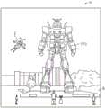
本文公开的各种实施例涉及便携式(例如,可穿戴)电子装置。例如,在图1中,描绘了增强现实场景4,其中AR技术的用户看到了一个真实的公园样场景6,背景中有人、树、建筑物和混凝土平台1120。除了这些项目之外,AR技术的用户还感知到他“看到”一个机器人雕像1110站在真实世界平台1120上,卡通化身角色2飞过,这似乎是一只熊蜂的拟人化,即使这些元素2、1110不存在于现实世界中。至少可以通过本文公开的便携式(例如,可穿戴)电子装置部分地向用户提供元素2、1110。事实证明,人类的视觉感知系统非常复杂,在其他虚拟或现实世界的图像元素中,产生一种舒适、自然、丰富的虚拟图像元素呈现的VR或AR技术具有挑战性。Various embodiments disclosed herein relate to portable (eg, wearable) electronic devices. For example, in Figure 1, an
例如,头戴式AR显示器(或头盔显示器,或智能眼镜)通常至少疏松第耦合到用户的头部,从而在用户的头部移动时移动。如果显示系统检测到用户的头部移动,则可以更新显示的数据,以考虑头部姿势的变化。For example, head-mounted AR displays (or helmet-mounted displays, or smart glasses) are typically at least loosely coupled to the user's head so as to move as the user's head moves. If the display system detects movement of the user's head, the displayed data can be updated to account for changes in head pose.
例如,如果佩戴头戴式显示器的用户在显示器上查看三维(3D)对象的虚拟表示,并绕着3D对象出现的区域行走,则可以为每个视点重新渲染该3D对象,从而让用户感觉到他或她绕着占用实际空间的对象行走。如果头戴式显示器用于在虚拟空间(例如,丰富的虚拟世界)中呈现多个对象,则可以使用头部姿势的测量(例如,用户头部的位置和取向)来重新渲染场景,以匹配用户动态变化的头部位置和取向,并提供更高的在虚拟空间中的沉浸感。For example, if a user wearing a head-mounted display views a virtual representation of a three-dimensional (3D) object on the display and walks around the area where the 3D object appears, the 3D object can be re-rendered for each viewpoint so that the user feels He or she walks around objects that take up actual space. If a head-mounted display is used to present multiple objects in a virtual space (eg, a rich virtual world), the measurement of the head pose (eg, the position and orientation of the user's head) can be used to re-render the scene to match The user dynamically changes head position and orientation and provides a higher sense of immersion in the virtual space.
在AR系统中,头部姿态的检测或计算可以帮助显示系统渲染虚拟对象,使其看起来以对用户有意义的方式占据现实世界中的空间。此外,检测与用户头部或AR系统相关的真实对象(例如手持装置(也可称为“图腾(totem)”)、触觉装置或其他真实物理对象的位置和/或取向也可有助于显示系统向用户呈现显示信息,以使用户能够有效地与AR系统的某些方面交互。当用户的头部在真实世界中移动时,虚拟对象可以作为头部姿势的函数重新渲染,使得虚拟对象相对于真实世界看起来保持稳定。至少对于AR应用,以对于物理对象的空间关系设置虚拟对象(例如,被呈现为在空间上在两个或三个维度上接近物理对象)可能是一个非微不足道的问题。例如,头部移动可能会使虚拟对象在环境视图中的放置变得非常复杂。无论是将视图捕获为周围环境的图像,然后投影或显示给最终用户,还是最终用户直接感知周围环境的视图,这都是正确的。例如,头部移动可能会导致最终用户的视野发生变化,这可能需要更新最终用户视野中显示各种虚拟对象的位置。此外,头部移动可能会在很大的范围和速度范围内发生。头部移动速度不仅可以在不同的头部移动之间变化,而且可以在单个头部移动的范围内或或该范围变化。例如,头部移动速度可能从一个起始点初始地增加(例如,直线或非直线),当到达终点时,头部移动速度可能会下降,在头部移动的起始点和结束点之间的某处获得最大速度。快速的头部移动甚至可能超过特定显示或投影技术向最终用户呈现均匀和/或平滑移动的图像的能力。In AR systems, the detection or calculation of head poses can help the display system render virtual objects so that they appear to occupy real-world space in a way that makes sense to the user. Additionally, detecting the position and/or orientation of real objects (eg, handheld devices (which may also be referred to as "totems"), haptic devices, or other real physical objects in relation to the user's head or AR system may also aid in the display The system presents display information to the user to enable the user to effectively interact with certain aspects of the AR system. As the user's head moves in the real world, virtual objects can be re-rendered as a function of the head pose such that the virtual objects are relatively The real world appears to remain stable. At least for AR applications, setting up virtual objects in spatial relationship to physical objects (eg being rendered spatially close to physical objects in two or three dimensions) can be a non-trivial problem For example, head movement can complicate the placement of virtual objects in the view of the environment. Whether the view is captured as an image of the surrounding environment and then projected or displayed to the end user, or the end user directly perceives the surrounding environment , which are all correct. For example, head movement may cause the end user's field of view to change, which may require updating the position where various virtual objects are displayed in the end user's field of view. Also, head movement may be in a wide range and speed range. Head movement speed can vary not only between different head movements, but also within or within a range of individual head movements. For example, head movement speed may start from a starting point increases substantially (e.g., straight or non-straight), when the end point is reached, the head movement speed may decrease, gaining maximum speed somewhere between the start and end points of the head movement. Fast head movements may even Exceeds the ability of a particular display or projection technology to present a uniform and/or smooth moving image to the end user.
头部跟踪的准确性和延迟(例如,从用户移动他或她的头部与图像被更新并显示给用户的时间之间经过的时间)一直是VR和AR系统面临的挑战。特别是对于那些用虚拟元素填充用户大部分视野的显示系统,如果头部跟踪的精度高并且从第一次检测头部移动到更新由显示器传送到用户的视觉系统的光的整个系统延迟非常低,则这是有利的。如果延迟高,系统会在用户前庭和视觉感觉系统之间造成不匹配,并产生导致恶心或模拟疾病用户感知场景。如果系统延迟高,则在快速头部移动期间,虚拟对象的明显位置将显得不稳定。Head tracking accuracy and latency (eg, the elapsed time between the user moving his or her head and the time the image is updated and displayed to the user) has been a challenge for VR and AR systems. Especially for display systems that fill most of the user's field of view with virtual elements, if the accuracy of the head tracking is high and the overall system latency from first detecting head movement to updating the light transmitted by the display to the user's visual system is very low , then this is beneficial. If the latency is high, the system can create a mismatch between the user's vestibular and visual sensory systems and create user perception scenarios that cause nausea or simulate illness. If the system latency is high, the apparent position of the virtual object will appear unstable during fast head movements.
除了头戴式显示系统外,其他显示系统还可以受益于准确和低延迟的头位检测。这些包括头部跟踪显示系统,其中显示器不在用户身体上佩戴,而是安装在例如墙壁或其他表面上。头部跟踪显示的作用类似于场景上的一个窗口,当用户相对于“窗口”移动头部时,场景将重新渲染以匹配用户不断变化的视点。其他系统包括头戴投影系统,其中头戴显示器将光线投射到现实世界。In addition to head-mounted display systems, other display systems can benefit from accurate and low-latency head position detection. These include head-tracking display systems, where the display is not worn on the user's body, but is mounted, for example, on a wall or other surface. The head tracking display acts like a window on the scene, and as the user moves the head relative to the "window", the scene re-renders to match the user's changing viewpoint. Other systems include head-mounted projection systems, where head-mounted displays project light into the real world.
此外,为了提供真实的增强现实体验,AR系统可以设计为与用户交互。例如,多个用户可以使用虚拟球和/或其他虚拟对象玩球类游戏。一个用户可以“接住”虚拟球,然后将球扔回另一个用户。在另一个实施例中,可向第一用户提供图腾(totem)(例如,与AR系统通信地耦合的真实球棒)以击打虚拟球。在其他实施例中,可以向AR用户呈现虚拟用户界面,以允许用户选择多个选项之一。用户可以使用图腾、触觉装置、可穿戴部件,或者只需触摸虚拟屏幕即可与系统交互。Furthermore, in order to provide a realistic augmented reality experience, AR systems can be designed to interact with the user. For example, multiple users may play ball games using virtual balls and/or other virtual objects. One user can "catch" the virtual ball and throw it back to another user. In another embodiment, a totem (eg, a real ball bat communicatively coupled with the AR system) may be provided to the first user to hit the virtual ball. In other embodiments, the AR user may be presented with a virtual user interface to allow the user to select one of multiple options. Users can interact with the system using totems, haptic devices, wearable parts, or simply touching a virtual screen.
检测用户的头部姿势和取向,以及检测空间中真实物体的物理位置,使得AR系统能够以有效和愉快的方式显示虚拟内容。然而,虽然这些能力是AR系统的关键,但很难实现。换句话说,AR系统可以识别真实对象(例如,用户的头部、图腾、触觉装置、可穿戴部件、用户的手等)的物理位置,并且将真实对象的物理坐标与对应于显示给用户的一个或多个虚拟对象的虚拟坐标相关联。这通常需要快速率跟踪一个或多个对象的位置和取向的高精度的传感器和传感器识别系统。目前的方法不能以令人满意的速度或精度标准进行定位。Detecting the user's head pose and orientation, as well as detecting the physical location of real objects in space, enables AR systems to display virtual content in an efficient and enjoyable way. However, while these capabilities are key to AR systems, they are difficult to achieve. In other words, the AR system can identify the physical location of real objects (eg, the user's head, totems, haptic devices, wearable components, the user's hands, etc.) and associate the physical coordinates of the real objects with the The virtual coordinates of one or more virtual objects are associated. This typically requires high-accuracy sensors and sensor recognition systems that track the position and orientation of one or more objects at a fast rate. Current methods cannot locate with satisfactory speed or accuracy standards.
因此,在AR和VR装置的背景下,需要更好的定位系统。此外,用户的持续和/或快速移动可能会给此类AR和/VR装置的电气、热力和/或机械系统带来各种其他问题。Therefore, in the context of AR and VR installations, better localization systems are needed. Furthermore, the constant and/or rapid movement of the user may cause various other problems to the electrical, thermal and/or mechanical systems of such AR and/VR devices.
参考图2A-2D,示例了一些通用部件选项。在图2A-2D的讨论之后的详细描述部分中,提出了各种系统、子系统和部件,以应对提供用于人类VR和/或AR的高质量、舒适感知的显示系统的这一目标。Referring to Figures 2A-2D, some common component options are illustrated. In the Detailed Description section following the discussion of Figures 2A-2D, various systems, subsystems, and components are presented to address this goal of providing a high-quality, comfortable-perceptual display system for human VR and/or AR.
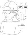
如图2A所示,AR系统用户60被描绘为佩戴头戴式部件58,其特征在于具有与位于用户眼前的显示系统62耦合的框架64结构。扬声器66在所描述的配置中耦合到框架64,并定位在用户的耳道附近(在一个实施例中,未示出的另一个扬声器定位在用户的另一耳道附近,以提供立体声/可整形声音控制)。显示器62通过有线引线或无线连接等方式操作地耦合到本地处理和数据模块70,本地处理和数据模块70可以通过各种配置安装,例如固定地附接到框架64,固定地附接到头盔或帽80,如图2B的实施例所示,嵌入在耳机中,在如图2C的实施例所示的背包式配置中可移除地附接到用户60的躯干82,或在如图2D的实施例所示的带耦合式配置中可移除地附接到用户60的臀部84。As shown in FIG. 2A, an
本地处理和数据模块70可以包括节能的处理器或控制器、以及数字存储器,例如闪存,两者都可以用于协助处理、缓存和存储:从可操作地耦合到框架64的传感器(例如图像捕获装置(例如照相机)、麦克风、惯性测量单元、加速计、罗盘、GPA单元、无线电装置和/或陀螺仪)捕获的数据a);和/或数据b),使用远程处理模块72和/或远程数据存储库74获取和/或处理,可用于在这样的处理或检索之后传送到显示器62。本地处理和数据模块70可以操作地耦合76、78(例如经由有线或无线通信链路)到远程处理模块72和远程数据存储库74,使得这些远程模块72、74彼此操作地耦合并且作为资源对于本地处理和数据模块70是可用的。Local processing and
在一个实施例中,远程处理模块72可以包括一个或多个相对强大的处理器或控制器,其被配置为分析和处理数据和/或图像信息。在一个实施例中,远程数据存储库74可以包括相对大规模的数字数据存储设施,其可以以“云”资源配置的形式通过因特网或其他网络配置可用。在一个实施例中,在本地处理和数据模块中存储所有数据并执行所有计算,允许来自任何远程模块的完全自主使用。In one embodiment,
本地处理和数据模块中的热缓解Thermal mitigation in local processing and data modules
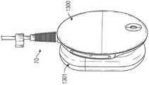
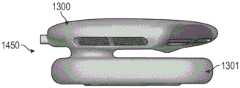
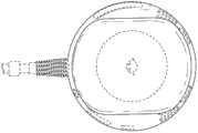
图3A是根据一个实施例的本地处理和数据模块70的前侧示意图。图3B是图3A的本地处理和数据模块70的示意右视图。如图3A和3B所示,本地处理和数据模块70可以包括包括第一壳体100和与第一壳体100机械连接的第二壳体101的外壳75。在一些实施例中,第二壳体101可与第一壳体100流体耦合。第一壳体100和第二壳体101被耦合以在其之间提供热隔离或分离,例如,壳体100、101之间的间隙(例如气隙)可以在其之间提供改进的热分离。因此,在一些实施例中,第一壳体可以包括第一隔间,该第一隔间通过在第一和第二壳体100、101之间提供热分离的间隙与在与第一隔间隔开的位置处的第二壳体101的第二隔间分离。然而,如下面进一步讨论的,在各种实施例中,在第二壳体101中产生的至少一些热可以流向第一壳体100。FIG. 3A is a front side schematic diagram of a local processing and
第一壳体100可以包括前侧102和与前侧102相对的背侧103。第二壳体101可与第一壳体的背侧103耦合。包括通道119的连接部分可以在第一和第二壳体100、101之间延伸。连接部分的通道119可以将第一壳体100中限定的内室或腔与第二壳体101中限定的内室或腔连接。如本文所解释的,在一些实施例中,通道119的尺寸被确定为容纳在第一和第二壳体100、101内的部件之间延伸的一个或多个电连接器。此外,通道119可以通过流体通信或其他方式在第一和第二壳体100、101之间提供热传递,例如,以改善外壳75内的散热。在其他实施例中,如本文所解释的,连接部分的通道119(和/或分隔壳体100、101的物理气隙)可以在第一和第二壳体100、101之间提供热间隙,以在壳体100、101之间提供热分离。在图3A-3B的实施例中,每个壳体100、101可包括具有内室或腔的盘状结构,内室或腔被成形为包含各种电子装置、热缓解特征和/或电源装置。在其它实施例中,壳体100、101可以被不同地成形。The
图3C是图3A-3B所示的本地处理和数据模块70的示意性后平面图。如图3C所示,外壳75(例如,在第一壳体100的周边)可以包括一个或多个用户接口106,所述用户接口106被配置成使用户能够控制系统的操作。例如,在一些实施例中,用户接口106可以包括按钮或其他类型的接口,以控制AR或VR体验的音量,和/或使音量静音。其他控制机制可以通过接口106实现。此外,本地处理和数据模块70可以包括一个或多个输入/输出(I/O)端口107,以提供输入和/或输出数据。例如,I/O端口107可以包括音频端口。Figure 3C is a schematic rear plan view of the local processing and
此外,本地处理和数据模块70可以包括一个或多个入口端口104A、104B,其被配置成允许气体(例如空气)进入外壳75,例如,在第一壳体100的周边上的位置。本地处理和数据模块70还可以包括一个或多个排放端口105,以允许气体(例如,空气)离开外壳75,例如,在第一壳体100的周边上的位置。这样,空气可以通过入口端口104a、104b流入壳体100,并且可以通过排放端口105从壳体100离开。端口104a、104b可以包括壳体100中位于壳体100周边上的间隔位置处的一个孔或孔阵列。端口105可以包括壳体100中的一个孔或孔阵列。如下面进一步讨论的,在一些实施例中提供一个风扇出口,并且在这些实施例中,可以提供单个端口105以用于从壳体100流出的流体通信。在一些实施例中,端口105可以设置在壳体100的多个周边侧上。端口104可以设置在壳体100的多个周边侧上。如本文所述,通过壳体100的气流可以有利地将热量从本地处理和数据模块70带走。Additionally, the local processing and
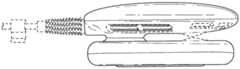
图3D是图3A-3C所示的本地处理和数据模块70的示意性侧面横截面图。如上所述,本地处理和数据模块70可以包括一个或多个电子部件109(这里以方框形式示意性地示出),例如处理器、存储器管芯、传感器等。在图3D的实施例中,电子部件109可设置在外壳的第一壳体100的室或第一隔间中。如所示,电子部件109可以设置在相对较低的轮廓(profile)和相对较小的横向足迹内。示例的电子部件109示出在第一壳体100的前侧102处或其附近,但是应当理解,可以在壳体100、101中任何合适的地方提供附加的电子部件。Figure 3D is a schematic side cross-sectional view of the local processing and
将多个电子部件109并入壳体100中可能产生大量热量,如果没有充分冷却,可能会对用户造成不适和/或损坏系统部件。因此,在各种实施例中,可以在外壳(例如,在第一壳体100中)中提供热缓解组件110,以去除由电子部件109产生的热,并在操作期间将外壳的温度保持在舒适和/或有效的水平。在所示实施例中,热缓解组件110设置在电子部件109的后部。在图3D所示的视图中,热缓解组件110可以包括设置在风扇组件111的第一侧上的第一热散布器112。第一热散布器112可以设置在风扇组件111的前侧,因此有时是前散布器。如本文所解释的,第一热散布器112可以与电子部件109机械和热耦合,以便将热传导到下面讨论的散热器或风扇组件111的部件。风扇组件111可以在热散布器112附近或上方吹入或吸入空气,以通过排放端口105将传热介质(例如,加热的空气或其他加热气体)从本地处理和数据模块70排出。Incorporating multiple
本地处理和数据模块70还可以包括第二壳体101内的附加电子部件(例如,板载(on-board)电源模块118),以向第一壳体100中的电子部件109提供电力,从而用户不需要连接到有线电源。例如,图3D所示的电源118可以包括一个或多个电池。板载电源可以在本地处理和数据模块70内产生附加热量。在一些实施例中,风扇组件111可以将传热介质(例如,加热空气或其他加热气体)从第二壳体101抽吸到第一壳体100,例如通过在壳体100、101之间提供流体通信的通道119。因此,在各种实施例中,热缓解组件110可以被配置成去除从电池(例如,电源118)和电子部件109中的一个或两个产生的热量。在各种实施例中,从本地处理和数据模块70去除的大部分热量可以包括由电子部件109产生的热量。The local processing and
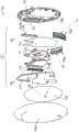
图4A是根据一个实施例的本地处理和数据模块70的第一壳体100的示意性透视分解图。如上结合图3A-3D所述,电子部件109可位于热缓解组件110前方的壳体100内。壳体100可以通过将前盖108a与后盖108b连接或配合而在结构上被界定或包含。当被连接时,前盖108a、后盖108b限定电子部件109和热缓解组件110设置在其中的室或第一隔间。尽管图4A示出了壳体100内的电子部件109和热缓解组件110,但是应当理解,可以在第一壳体100中提供附加部件。4A is a schematic perspective exploded view of the
如图4A所示,热缓解组件110可以包括支撑热缓解组件110的各种部件的底座115。例如,如图4A所示,第一热撒布器112和热传输路径117(例如,热管)可以被安装在基座115上或与之耦合。然而,在一些实施例中,组件110可以不包括基座115,使得第一热撒布器122和热传输路径117可以被设置在风扇组件111附近或以其他方式连接到风扇组件111。此外,散热器113(例如,金属板或元件的翅片叠层)可以安装到基座115上或与基座115耦合。例如,散热器113可以包括连接的铜翅片图案,每个翅片的厚度在0.05mm到0.35mm的范围内,例如在0.1mm到0.3mm的范围内(在一些实施例中约为0.2mm)。翅片的间距可以在0.25mm到2mm的范围内,或者在0.5mm到1.5mm的范围内(在一些实施例中约为1mm)。第二热散布器114可以设置在风扇组件111的第二侧。第二热散布器114可以设置在风扇组件111的后侧,因此有时是后热散布器。在一些实施例中,第一热散布器112可以通过任何合适的连接器(例如导热连接器、热间隙垫、热粘合剂等)热地并且可选地机械地耦合到一些或所有电子部件109。例如,电子部件109产生的热可以通过一个或多个热间隙垫传导到第一热散布器112,该热间隙垫可以包括导热弹性体。热间隙垫可在热撒布器112和部件之间产生压力,以改善热导率。热可以沿着热传输路径117从热撒布器112和/或电子部件109传送到散热器113。As shown in FIG. 4A ,
风扇组件111可以在第一热散布器112、热传输路径117和/或第二热散布器114上方和/或周围驱动或抽吸空气,以冷却第一壳体100和/或第二壳体101。例如,风扇组件111可以通过入口端口104a、104b将流入空气A1吸入到第一壳体100中。风扇组件111可以在第一壳体100内和电子部件109上方和/或周围循环冷却空气A2以冷却电子部件109。在一些实施例中,冷却空气A2可以包括吸入壳体100内而无需额外冷却的环境空气。此外,如图4A所示,风扇组件111可以从第二壳体101(例如经由通道119)将冷却空气A3吸入第一壳体100。因此,在所示的实施例中,电子部件109可以由在壳体100内循环的冷却空气A2冷却。
在一些实施例中,也可以通过从第二壳体101吸入到第一壳体100中的冷却空气A3来冷却电池或电源118。在一些实施例中,来自第二壳体101的热也可以通过热导体传导到第一壳体100中,并通过本文所述的气流耗散。在一些实施例中,如本文所解释的,包括通道119的连接部分可以包括隔热间隙,以减轻或减少从第一壳体100到第二壳体101的热流(或反之亦然)。冷却空气流A2和A3可被抽吸或吸入到在风扇组件111的内部部分(例如,中心部分)中形成的气流开口129中。在一些实施例中,例如,冷却空气A2可以在第一热散布器112或基座115和风扇组件111之间横向通过,并且可以通过开口129进入风扇组件111。如本文所述(参见图4C和4E),通过风扇组件111的气流开口129吸入的空气可以通过风扇组件111的出口空气开口132以流出空气流A4的形式径向向外排出。因此,在各种实施例中,风扇组件111的空气路径可以在沿纵向轴L设置的空气流开口129和围绕相对于纵向轴L的非平行轴设置的具有的面的出口空气流开口132之间延伸。例如,出口空气开口132可以被径向向外设置(例如,一般垂直于纵向轴L)。径向流出空气流A4可以被引导到散热器113上,以将存储在散热器113中的热能从壳体100中取出。如图4A所示,排出的空气A5可以通过排放端口105被引导出第一壳体100,到达外部环境。In some embodiments, the battery or power source 118 may also be cooled by cooling air A3 drawn from the
图4B是根据另一实施例的本地处理和数据模块70的示意透视分解图。除非另有说明,否则图4B的本地处理和数据模块70可以类似于图4A的本地处理和数据模块70。与图4A的实施例不同,在图4B中,仅示出单个入口端口104和单个排放端口105。因此,应当理解,可以提供任意适当数量的入口端口104和/或出口端口105,用于将空气吸入壳体100和将空气排出壳体100。FIG. 4B is a schematic perspective exploded view of the local processing and
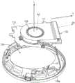
图4C是安装到第一热散布器112上的风扇组件111的示意性部分分解图。图4D是风扇组件111、热散布器112、热传输路径117和散热器113的示意性部分分解图。如图4A-4C所示,电子部件109可设置在前盖108a附近,第一热散布器112可设置在电子部件的后部,以及风扇组件111可与第一热散布器112热耦合并设置在其后部。第一热散布器112可以设置在电子部件109和风扇组件111之间。风扇组件111可与第一热散布器112热耦合。在一些实施例中,可以在风扇组件111和热散布器112或底座115之间设置间隙,以允许空气进入开口129。在图4C中,底座115和热传输路径117被遮挡,因为底座115和传送路径117可以设置在热散布器112和风扇组件111之间。如上结合图4A所述,出流空气流A5可以通过设置在风扇组件111的出口开口132附近(例如,上游)的散热器113(在图4C中被遮挡)。FIG. 4C is a schematic partially exploded view of the
如图4C所示,风扇组件111可包括旋转轴L和相对于轴L(例如,垂直)不平行的横轴T。旋转轴L是风扇组件111的一部分围绕其旋转的轴组件或轴部分的纵向轴,以及由此有时称为纵向轴L。冷却空气流A2(见图4D)和A3(参见图4C和4D)可以通过空气流开口129从外壳100、101中的热源(例如,分别地从电子部件109和电源118)进入风扇组件111。在一些设置中,例如,空气流A2可以在热散部器112或底座115和风扇组件111之间通过,并且可以进入开口129。冷却空气流A2、A3可以具有至少局部地在开口129附近和在风扇组件111的相对侧上的对应开口处的沿着纵向轴L对准的速度分量。因此,风扇组件111的叶片的旋转可以沿着纵向轴以高动量将空气吸入风扇组件111。出流空气流A4可以径向地向外通过出口开口132,使得空气流A4包括沿横向轴T对准的速度分量。出流空气流A4可以通过排放端口105离开壳体100(参见图4A~4B)。As shown in FIG. 4C , the
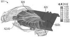
图4E示出了在风扇组件111的操作期间组装的热散布器、热传输路径117和散热器113的热图。利用计算流体力学(CFD)软件计算了热图。如图4D和4E所示,热传输路径117可与热撒布器112耦合,例如,设置在热撒布器112的沟槽或通道中。热散布器112可以包括导热材料,例如铜。热传输路径117可以包括热管,热管包括热传导通道。工作流体(例如,水)可设置在热传输路径117的腔中。在各种实施例中,传输路径117的热管可包括被扁平化以具有通常为椭圆形的横截面轮廓的铜管。在各种实施例中,例如,热管的主尺寸可以为热管的次尺寸的2到10倍(例如,为5到9倍)。FIG. 4E shows a thermal map of the heat spreader,
如图4E所示,热能Q可以从部件109存储在和/或传导到热散布器112。来自热散布器112的热能Q可以沿着一个或多个热路径Q1、Q2传输到散热器113。例如,如图4E所示,一些热能可以经由热传递路径117沿着第一路径Q1从热撒布器112传递。通过利用导热管状构件内的具有高热容量的工作流体,热能可以快速有效地转移到散热器113。第二路径Q2可以沿着热撒布器112的区域将热能传送到散热器。如图4E所示,代表第一路径Q1的箭头比代表第二路径Q2的箭头宽,这表明热量沿着第一路径Q1比第二路径Q2更有效和/或更快地传递。在各种实施例中,传送路径117可以显著地比第一热散布器112更导热(例如,至少是热散布器112的五倍或至少十倍)。As shown in FIG. 4E , thermal energy Q may be stored and/or conducted from
如图4E所示,在风扇组件111的操作过程中,如通过散热器113上方的气流保持的相对冷的温度所示,热可以通过出流空气流A4迅速地从散热器转移。将散热器113保持在冷的温度可以增加热散布器112和/或热传输路径117与散热器113之间的热梯度。有利地,所公开的实施例可以将本地处理和数据模块70的温度保持在适当的低温。As shown in Figure 4E, during operation of the
图5是可与本文所述的本地处理和数据模块70一起使用的风扇组件211的示意性侧截面6图。风扇组件211可以包括支撑框架222,其被配置为向风扇组件211提供结构支撑。框架222可以包括通过例如紧固件或其他机械连接器连接在一起的多个框架部分。在其他实施例中,框架222可以包括整体的体。马达220可以与机架222机械地耦合。轴组件223可以被连接到马达220,并且可以沿着上述纵轴L延伸,使得纵轴在轴组件223的第一和第二端之间延伸和/或穿过该第一端和第二端延伸。在图5的实施例中,其中轴组件223连接到马达220,轴支撑马达220可被视为支撑框架222或框架组件的一部分。在所示的设置中,轴组件223相对于马达220或机架222悬臂式。如本文所解释的,在一些实施例中,轴组件223可以包括单个轴。在其他实施例中,轴组件223可以包括耦合在一起的多个轴。轴承224可以是衬套,可以至少部分地设置在轴组件223周围。叶轮221可操作地与衬套或其他轴承224耦合并设置在其周围。5 is a schematic side sectional 6 view of a
在一些实施例中,马达220可包括定子(未示出),其具有一个或多个线圈,当通过电力供能时,该线圈产生足以驱动与叶轮221耦合或由叶轮221形成(例如,在叶轮221的毂或其他中心部分内或上)的磁性转子组件(未示出)的变化或交替磁场。马达220产生的磁场可以与叶轮221的磁转子组件相互作用,使磁性转子以及由此的叶轮221绕纵向轴L旋转。在所示的实施例中,轴组件223可以固定到马达220或框架222。因此,在所示的实施例中,轴组件223可以不旋转。在一些实施例中,衬套或其他轴承224可以附接在轴组件223上或固定到轴组件223,并且叶轮221可以相对于衬套224和轴组件223旋转。在一些实施例中,衬套或其他轴承224可以附接或固定到叶轮221,并且可以与叶轮221相对于轴组件223旋转。在其他实施例中,应当理解,马达220可以包括导致轴组件223(或其部分)旋转的内部定子和转子组件。在这种设置中,叶轮221可以相对于轴组件223旋转固定并且可以与轴组件223一起旋转。In some embodiments,
可以驱动叶轮221高速旋转,以便充分地从外壳中除去热能。例如,叶轮221可以在5000rpm到10000rpm之间的速度(例如8000rpm)或在更高的速度下旋转。如上所述,本地处理和数据模块70可以由用户佩戴或以其他方式携带以用于VR或AR体验。用户在佩戴模块70的同时可能通常正在移动,因此,本地处理和数据模块70以及其中的风扇组件211通常可以相对于重力g以不同的角度设置。然而,在某些情况下,风扇组件211可以以一定的角度设置,或者可以以足够高的加速度移动,使得轴组件223上横向载荷产生的扭矩使轴组件223弯曲或屈伸一角度p,如图5所示。轴组件223由于横向载荷条件而发生挠曲(deflection)或弯曲,可能导致叶轮221接触或撞击框架222的内表面,这可能在本地处理和数据模块70内引起不希望的噪声和/或振动。此外,频繁地向轴组件223施加这种外部扭矩可能导致轴组件223磨损或经历疲劳,这会损坏轴组件。The
因此,可以期望减少或消除由于在轴组件223上施加横向载荷(以及由此产生的扭矩)而引起的噪声和振动,并且减少或消除疲劳或磨损的影响。本文所公开的实施例可以有利地控制横向于图5所示的纵向轴L的载荷。在一些设置中,例如,可以使轴组件223具有足够的刚度,以减少轴组件223的远端的挠曲量。在其它设置中,框架222上的元件可有助于防止叶轮221和轴组件223接触框架222或基本挠曲。例如,在一些实施例中,围绕叶轮221设置的框架的框架部分222’可以包括与叶轮221中的对应磁体对准的一个或多个磁体。例如,框架部分222'和叶轮中的磁体可以具有对准的相似极,以使叶轮221保持在框架222内的中心位置,或者至少抵抗在横向载荷下叶轮221朝框架222的挠曲,其可减少或消除轴组件223的挠曲。Accordingly, it may be desirable to reduce or eliminate noise and vibration due to the application of lateral loads (and thus torque) on
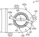
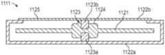
图6是根据本文公开的各种实施例的风扇组件311的后平面视图。图7是图6的风扇组件311的示意性侧截面图。除非另有说明,图6和图7中所示的部件可以包括类似于图5中所示的相似编号部件的部件。如图6和7所示,风扇组件311可以包括框架组件,其可以具有耦合到第一框架322a的第一支撑框架322a和第二支撑框架322b。连接的第一和第二支撑框架322a、322b可以限定壳体或室。叶轮321可以设置在第一和第二支撑框架322a、322b之间,例如,在由框架322a、322b限定的壳体内。因此,在所示的实施例中,第一和第二支撑框架322a、322b可以限定其中设置有叶轮321的外壳。图6和7中的叶轮321可以包括毂327和一个或多个与毂327耦合和/或从毂327延伸的叶片328(例如,风扇叶片)。毂327可以与轴组件323耦合。在一些实施例中,衬套可以设置在轴组件323和毂327之间。如上所述,在一些实施例中,叶轮321可以相对于旋转固定轴组件323旋转。在其它实施例中,叶轮321可与转轴组件323一起旋转。FIG. 6 is a rear plan view of
如图7所示,轴组件323的第一端333可以由第一支撑框架322a支撑或与第一支撑框架322a耦合(例如,到由框架限定或包括框架的支撑结构,或到马达等)。例如,在图7的实施例中,轴组件123的第一端333可以在第一支撑框架322a的第一轴支撑330处固定到第一框架322a。在各种实施例中,第一端333可以焊接、粘合或压配(press fit)到框架322a上。第一轴支撑330可以包括由第一支撑框架322a限定的结构体的一部分。在其他实施例中,第一支撑框架322a可以包括马达,以便轴组件323的第一端333被固定到马达并且轴支撑330包括马达的一部分。应当理解,任何合适的结构都可以用作轴支撑330,以固定轴组件323的第一端333。As shown in FIG. 7, the
如上所述,控制施加在轴组件323上的横向载荷有利于降低噪声和振动,并降低疲劳、磨损或过度载荷条件的风险。因此,在图6和7的实施例中,可以提供第二支撑框架322b以控制轴组件323上的横向载荷。第二支撑框架322b可以与第一支撑框架322a耦合,并且可以设置在轴组件323的第二端334处或其上方,以控制轴组件323的第二端334处的横向载荷。在图6和图7中,第二支撑框架322b可以包括与轴组件323的第二端334耦合的第二轴支撑326。第二轴支撑326可以跨空气流开口329的至少一部分牢固地附接到第二支撑框架322b。在一些实施例中,第二轴支撑326可以包括销或其他连接器,其刚性地将轴组件323的第二端334附接到框架322b。在各种实施例中,第二轴支撑326(例如,销)可以相对于轴L同心或轴向连接,轴组件323、叶轮321或轴组件323和叶轮二者围绕轴L旋转。将第二轴支撑326沿轴L定位或相对于轴L中心定位可以有利地减小挠曲并改善叶轮321的旋转。As discussed above, controlling the lateral loads imposed on the
在图6和7的实施例中,第二轴支撑326可以包括伸长构件325或连接在伸长构件325的第一和第二端部335a、335b之间与伸长构件325连接。如图6所示,伸长构件325的第一端部335a可以支撑在第二支撑框架322b的第一部分处,以及伸长构件325的第二端部335b可以支撑在第二支撑框架322b的第二部分处。第一和第二端部335a、335b(以及第二框架322b的相应的第一和第二部分)可以在空气流开口329的周边隔开。在所示的实施例中,例如,第一和第二端部335a、335b(以及框架322b的第一和第二部分)可以设置在空气流开口329的大致相对侧上。然而,在其它实施例中,伸长构件325的第一和第二端部335a、335b可以周边地间隔小于180°。例如,伸长构件325可以从第一端部335a延伸到空气流开口329上方,并且与轴组件的第二端334连接。伸长构件325可以以小于180°的角度从第二端334进一步延伸到第二端部分335b。In the embodiment of FIGS. 6 and 7 , the
除了支撑第一端333之外,刚性支撑轴组件323的第二端334可以有利地控制轴组件323上的横向载荷,并且可以减少或消除组件323的挠曲。然而,由于伸长构件325可设置为跨部分或整个空气流开口329,因此伸长构件325会干扰通过空气流开口329进入风扇组件311的进气。因此,在所示的实施例中,伸长构件325可以相对于所述横向轴T成选择或确定的角度A,以便减少或最小化流入空气的扰乱(例如,使得进入开口329的空气流被最大化或充分地增加以用于热设计目标)。例如,在一些实施例中,计算技术(例如计算流体动力学或CFD)可以计算通过马达组件311的估计空气流场。分析或计算可以确定用于定向伸长构件325的希望的角度A。在各种实施例中,希望的角度A可以对应于,与伸长构件325的角度A的范围(伸长构件325被附接到框架322b)相比较的,当叶轮321旋转时的空气流的整体或局部最大值。在一些实施例中,在风扇组件311的操作期间,可以应用计算技术而无需伸长构件325来确定与开口329周围的其它位置相比空气流较少的开口329的位置。如果发现最小或减小的空气流区域(没有附接伸长构件325),则伸长构件325的希望位置或取向可与这些较小空气流的区域相对应。在所示的实施例中,可以希望将伸长构件325相对于横向轴T以足够小的角度取向,以便空气可以以围绕处于这样的角度的伸长构件325的相对薄的轮廓流动。在各种实施例中,角度A可以在-45°到45°的范围内,例如在-30°到30°的范围内。然而,应当理解,根据风扇组件311的特定流动动力学,可以使用其他角度A。有利的是,在各种实施例中,制造商或组装商可以相应地装配风扇组件311,并且基于在没有伸长构件325的风扇组件311的操作期间确定的较小空气流区域,制造商可以定位伸长构件325,以最小化对空气流的干扰(例如,通过将伸长构件325定位在这些最小流动区域之上)。在组装过程期间且在计算最小气流模式之后对伸长构件325进行定向,可以使制造商或组装商了解在加长伸长构件325之前被冷却的装置的特定气流模式。In addition to supporting the
如下面进一步讨论的,伸长构件325的取向通常可以横向于框架322a上方和通过开口329(或通过框架322b中的开口)的局部较大或全局最大气流的方向。伸长构件325可以被取向为具有面对这种更大或最大空气流状态的最小轮廓。As discussed further below, the orientation of elongate member 325 may generally be transverse to the direction of local greater or global maximum airflow over
图6A-6F示出了本文所述的伸长构件325的各种顶部和侧面轮廓。例如,图6A是伸长构件325a的俯视示意图,其具有沿x-y平面的一般直轮廓,该x-y平面通常与叶轮321的旋转平面平行,例如,叶轮321可以在大致平行于图6所示的X-Y平面的平面内旋转,使得X-Y平面可以横向于旋转纵向轴L。图6B是具有第一弯曲区域361a和第二弯曲区域361b的伸长构件325b的示意顶平面视图。在图6B中,第一和第二弯曲区域361a、361b可在过渡区域360处或其附近反转弯曲的方向。例如,过渡区域360可以作为第一和第二区域361a、361b改变弯曲方向的转折区域。类似地,图6C是根据另一实施例的具有第一弯曲区域361a和第二弯曲区域361b的伸长构件325C的示意性俯视图。与图6B不同,在图6C中,第一和第二弯曲区域361a、361b可以沿平滑或连续的转折或过渡区域360改变弯曲方向。可选择从顶向下视图(例如,沿x-y平面)所示的形状,以便通过风扇组件获得所需的流动分布。6A-6F illustrate various top and side profiles of the elongate members 325 described herein. For example, FIG. 6A is a schematic top view of elongate member 325a having a generally straight profile along the x-y plane that is generally parallel to the plane of rotation of
图6D是一个伸长构件325d的示意侧视图,其沿大致横向于X-Y平面限定的X-Z平面,例如,平行于X-Y平面的方向(见图7所示的X-Z平面),具有大致平面或直轮廓。图6E是沿x-z平面观看的具有非直线或形状轮廓的伸长构件325e的示意侧视图。例如,如图6E所示,伸长构件325e可以包括沿z轴(其可以平行于或大致与纵向轴L对准)的第一位置设置的第一部分362a和沿z轴从第一部分362a偏移设置的第二部分362b。第三过渡部分362c可用于连接第一和第二部分362a、362b。Figure 6D is a schematic side view of an
图6F是根据另一实施例沿x-z平面观看的具有非直线或弯曲轮廓的伸长构件325f的侧视图示意图。与图6E的实施例一样,伸长构件325f可以包括沿着z轴的第一位置的第一部分363a,以及沿z轴的其他位置处的一个或多个第二部分363b。与图6E的实施例不同,图6F的构件325f可以包括沿z轴的弯曲表面。因此,如图6A-6F所示,伸长构件325的形状可以在x-y平面和/或x-z平面内变化。相应地,伸长构件325a-325f的形状可以具有任何适当类型的三维轮廓,以改善通过风扇组件的流动。6F is a schematic side view of an
图8是根据另一实施例的风扇组件411的后平面图。除非另有说明,图8中所示的部件可以包括与图6-7中所示相似编号的部件类似的部件,附图标记相对于图6-7递增100。然而,与图6和7的实施例不同,图8中所示的伸长构件425可以具有翼型形状,以便进一步改善通过风扇组件411的流动。在一些实施例中,伸长构件425的厚度可以沿伸长构件425的长度在第一和第二端部435a、435b之间变化。在一些实施例中,伸长构件425的宽度可以沿伸长构件425的长度在第一和第二端部435a、435b之间变化。在各种实施例中,可选择伸长构件425的宽度和/或厚度足够强,以便在预期的横向载荷条件下支撑轴组件423并容纳诱导的应力。因此,图8的实施例还可以有利地控制轴组件423上的横向载荷,同时保持通过风扇组件411的足够空气流。8 is a rear plan view of a
图9是根据另一实施例的风扇组件511的示意侧截面图。除非另有说明,图9中所示的部件可以包括类似于图6-8中所示的相似编号部件的部件,附图标记相对于图8递增100。例如,与图6-8的实施例一样,风扇组件511可以包括与轴组件523耦合的叶轮521(例如,通过衬套524)。此外,如图6-8所示,轴组件523的第一端533可以固定或附接到第一框架522a,例如,在第一轴支撑530处,该第一轴支撑530可以设置在马达520处或马达520上,或者在框架522a限定的结构体上。此外,与图6-8相同,轴组件523的第二端533可以固定或附接在第二轴支撑526处的第二框架522b上,第二框架522b也可以包括伸长构件525。有利的是,第一和第二轴支撑526可以控制轴组件523上的横向载荷,并且可以减少轴组件523的挠曲。此外,如上所述,在一些实施例中,可以选择伸长构件525的角取向,以便改善通过风扇组件511的流动,或者在某些情况下最小化将伸长构件525包括在空气流中的气流成本。9 is a schematic side cross-sectional view of a
然而,与图6-8的实施例不同,在图9中,轴组件523可以包括旋转固定(例如,附接)到第一支撑框架522a的第一轴部分523a和旋转固定(例如,附接)到叶轮521的第二轴部分523b。如图9所示,轴组件523的第一端533可以设置在叶轮521的第一侧上,轴组件523的第二端534可以设置在叶轮521的与第一侧相对的第二侧。第二轴部分523b可以在第一轴部分523a的自由端上和/或相对于第一轴部分523a的自由端旋转。在一些实施例中,第一和第二轴部分523a、523b可以包括连接在一起的两个单独的轴,例如在叶轮521处。在一些实施例中,第一和第二轴部分523a、523b可以包括单轴,其中第一部分523a位于叶轮521的第一侧,以及第二部分523b位于叶轮521的第二侧。However, unlike the embodiment of Figures 6-8, in Figure 9, the
因此,在图9的实施例中,第一轴部分523a可以相对于第一框架522a(例如,马达520或框架522a的结构体)旋转固定。第二轴部分523a可以与叶轮521和衬套524一起旋转。与上述实施例一样,用第二框架522b支撑轴组件523的第二端534可以有利地控制横向加载条件并减少轴组件523的挠曲。Therefore, in the embodiment of FIG. 9, the
图10是根据另一实施例的风扇组件611的示意侧截面图。除非另有说明,图10中所示的部件可以包括类似于图6-9中所示的相似编号部件的部件,附图标记相对于图9递增100。例如,与图9相同,轴组件623的第一端633可操作地与第一框架622a(其可包括框架的结构体、马达620或风扇组件611的任何其他合适的固定特征)耦合。轴组件623的第二端634可以与第二框架622b可操作地耦合。在图10中,为了便于说明,叶轮621和轴组件623在部分分解图中示出。然而,在操作过程中,应当理解,轴组件623的第一端633与第一框架622a接合,轴组件623的第二端634与第二框架622b接合。10 is a schematic side cross-sectional view of a fan assembly 611 according to another embodiment. Unless otherwise indicated, the components shown in FIG. 10 may include components similar to like-numbered components shown in FIGS. 6-9 with reference numerals incremented by 100 relative to FIG. 9 . For example, as in FIG. 9, the first end 633 of the shaft assembly 623 is operably coupled to the first frame 622a (which may include the structure of the frame, the motor 620, or any other suitable securing feature of the fan assembly 611). The second end 634 of the shaft assembly 623 can be operably coupled with the second frame 622b. In Figure 10, the impeller 621 and shaft assembly 623 are shown in a partially exploded view for ease of illustration. During operation, however, it should be understood that the first end 633 of the shaft assembly 623 is engaged with the first frame 622a and the second end 634 of the shaft assembly 623 is engaged with the second frame 622b.
此外,与图9相同,叶轮621可以与轴组件623的第一和第二轴部分623a、623b耦合。第一和第二轴部分623a、623b可以包括单个整体轴,或者第一和第二轴部分623a、623b可以包括两个单独的轴。在图10的实施例中,轴部分623a、623b可以固定到叶轮621,以便使叶轮621旋转。例如,叶轮毂627的一部分可以包括跟随磁体或转子组件。马达620的定子组件可以被供能,以便在毂627上产生磁力以使叶轮621旋转。此外,如图10所示,包括第一衬套624a的凹面构件可以与第一框架622a和/或马达620耦合或由其形成。包括第二衬套624b的第二凹面构件可以与第二框架622b耦合或由其形成。第一衬套624a可以充当第一轴支撑630以旋转地支撑轴组件623的第一端633,并且第二衬套624B可以充当或包括第二轴支撑626以旋转地支撑轴组件623的第二端634。因此,在叶轮621的旋转期间,第一轴部分623a的第一端633可以在第一衬套624a内旋转。第二轴部分623a的第二端634可以在第二衬套624b内旋转。Furthermore, the impeller 621 may be coupled to the first and second shaft portions 623a, 623b of the shaft assembly 623 as in FIG. 9 . The first and second shaft portions 623a, 623b may comprise a single integral shaft, or the first and second shaft portions 623a, 623b may comprise two separate shafts. In the embodiment of FIG. 10 , the shaft portions 623a, 623b may be fixed to the impeller 621 so as to rotate the impeller 621 . For example, a portion of the impeller hub 627 may include a follower magnet or rotor assembly. The stator assembly of the motor 620 may be powered to generate a magnetic force on the hub 627 to rotate the impeller 621 . Additionally, as shown in FIG. 10 , a concave member including a first bushing 624a may be coupled to or formed from the first frame 622a and/or the motor 620 . A second concave member including a second bushing 624b may be coupled with or formed from the second frame 622b. The first bushing 624a may serve as a first shaft support 630 to rotatably support the first end 633 of the shaft assembly 623 and the second bushing 624b may serve as or include a second shaft support 626 to rotatably support the second end 633 of the shaft assembly 623 . end 634. Therefore, during rotation of the impeller 621, the first end 633 of the first shaft portion 623a may rotate within the first bushing 624a. The second end 634 of the second shaft portion 623a can rotate within the second bushing 624b.
有利的是,第二衬套624b可以在风扇组件611的操作期间协助控制轴组件624上的横向载荷。如图所示,轴支撑626的第二衬套624b可以沿着第二轴部分623b对准或相对于第二轴部分623b同心对准。在一些实施例中,第二轴支撑626还可以包括延伸跨过部分或整个空气流开口629的伸长构件625。如图10所示,第一和第二衬套624a、624b中的一个或两者可包括凹面构件,例如凹面内表面。在一些实施例中,凹面内表面可包括或限定一般或基本上为球形的表面。在第一和/或第二衬套624a、624b中限定的凹面内表面可有利地允许轴组件623旋转,同时支撑轴组件623的两端633、634以抵抗横向载荷条件。此外,第一和/或第二衬套624a、624b的凹面内表面被成形为容纳轴组件623的端部633、634的小但可接受的旋转和/或平移。容纳这样可以忽略不计的端部633、634的移动可以进一步降低轴组件623上的应力,同时防止不期望的大变形。Advantageously, the second bushing 624b may assist in controlling lateral loads on the shaft assembly 624 during operation of the fan assembly 611 . As shown, the second bushing 624b of the shaft support 626 may be aligned along the second shaft portion 623b or concentrically aligned relative to the second shaft portion 623b. In some embodiments, the second shaft support 626 may also include an elongated member 625 extending across a portion or the entire air flow opening 629 . As shown in FIG. 10, one or both of the first and second bushings 624a, 624b may include a concave member, eg, a concave inner surface. In some embodiments, the concave inner surface may comprise or define a generally or substantially spherical surface. Concave inner surfaces defined in the first and/or second bushings 624a, 624b may advantageously allow the shaft assembly 623 to rotate while supporting the ends 633, 634 of the shaft assembly 623 against lateral loading conditions. Additionally, the concave inner surfaces of the first and/or second bushings 624a, 624b are shaped to accommodate small but acceptable rotation and/or translation of the ends 633, 634 of the shaft assembly 623. Accommodating such negligible movement of the ends 633, 634 can further reduce the stress on the shaft assembly 623 while preventing undesirably large deformations.
图10A-10D示出了可结合本文公开的实施例使用的风扇组件的附加示例。例如,图10A是包括轴组件923的风扇组件911的侧视示意图,轴组件923通过衬套924可操作地与叶轮组件921耦合。除非另有说明,图10A中所示的部件可以包括类似于图6-10中所示的相似编号部件的部件,附图标记相对于图10递增100。在图10A的实施例中,轴组件923可以包括单个轴,其端部可以连接到框架922a、922b(例如,焊接到伸长构件925或框架922b,机械固定或以其他方式固定)。在一些实施例中,框架922b中的一个可以包括伸长构件925。在图10A中,轴组件923可以包括与衬套924和叶轮921分离的构件,例如,图10A的轴组件923不与衬套924整体形成。在图10A中,轴组件923可以或不可以旋转地固定到衬套924上。例如,在一些实施例中,轴组件923可以不旋转地固定到衬套924,使得衬套924和叶轮921可以相对于固定轴组件923旋转(例如,可以围绕轴组件旋转)。在其他实施例中,衬套924和叶轮921可以旋转地固定或耦合到轴组件923,使得叶轮921和衬套924随着随轴组件923的旋转而旋转或跟随轴组件的旋转。10A-10D illustrate additional examples of fan assemblies that may be used in conjunction with embodiments disclosed herein. For example, FIG. 10A is a schematic side view of a
图10B是包括轴组件1023的风扇组件1011的示意侧视图,轴组件1023通过衬套1024可操作地耦合到叶轮组件1021。除非另有说明,图10B所示的部件可以包括类似于图6-10A所示的相似编号部件的部件,其附图标记相对于图10A递增100。与图10A的实施例不同,在图10B的实施例中,轴组件1023可与叶轮1021(和/或与衬套,未示出)物理集成,以限定单个整体轴组件和叶轮。因此,在图10B中,轴组件1023可以在其端部固定到框架1022a、1022b(其中之一可以包括伸长构件1025)。轴组件1023的旋转可使整体成形的叶轮1021旋转。10B is a schematic side view of
图10C是风扇组件1111的示意侧视图,该风扇组件包括轴组件1123,轴组件具有可操作地与叶轮1121耦合的第一和第二轴部分1123a、1123b。除非另有说明,图10C中所示的部件可以包括类似于图6-10B中所示的相似编号部件的部件,附图标记相对于图10B增加100。在图10C的实施例中,第一和第二轴部分1123a、1123b可以包括分别与框架1122a、1122b耦合的单独的轴。第一和第二轴部分1123a、1123b可以通过毂1124连接到叶轮1121。在图10C中,第一和第二轴部分1123a、1123b可以固定在框架1122a、1122b上,使得叶轮1121和毂1124相对于轴部分1123a、1123b旋转。在其他实施例中,第一和第二轴部分1123a、1123b可以固定到毂1124,使得毂1124和叶轮1121可以随第一和第二轴部分1123a、1123b旋转。10C is a schematic side view of a
图10D是风扇组件1211的侧视图示意图,该风扇组件包括轴组件1223,轴组件1123具有可操作地与叶轮1221耦合的第一和第二轴部分1223a、1223b。除非另有说明,图10D中所示的部件可以包括类似于图6-10C中所示的相似编号部件的部件,附图标记相对于图10C增加100。与图10C的实施例不同,例如,第一轴部分1223a可以与第一框架1222a集成形成,例如,第一轴部分1223a和第一框架1222a可以限定单个整体部件,使得第一轴部分1223a从第一框架1222a延伸。类似地,第二轴部分1223b可以与第二框架1222b集成形成,例如,第二轴部分1223b和第二框架1222b可以限定单个整体部件,使得第二轴部分1223b从第二框架1222b延伸。在一些实施例中,第一和第二轴部分1223a、1223b可以固定,使得毂1224和叶轮1221相对于轴部分1223a、1223b旋转。10D is a schematic side view of a
图11是在伸长构件725被附接到风扇组件711之前风扇组件711内的流动模式的平面图。图12是在伸长构件825相对于风扇组件811放置在所需取向之后风扇组件811内部和周围的流动模式的示意透视图。使用计算流体力学(CFD)技术计算图11和图12的流动模式。FIG. 11 is a plan view of the flow pattern within
图11表示流入风扇组件711的空气流开口729的冷却空气流A2、A3(见图4A)的速度场,在没有或在附接接伸长构件725之前。如上所述,风扇组件711可以与各种类型的便携式电子装置一起使用,这些便携式电子装置可以包括不同类型或数量的电子部件。一旦电子装置设计完成,就可以计算通过风扇组件711的流动模式,以确定风扇组件711在操作期间的速度场,并考虑外壳内的电子部件。对于图11所示的组件711,当与本地处理和数据模块70一起使用时,可以确定代表最大或增加空气流的周向位置Cmax。相似地,可以确定代表最小或减小的空气流的周向位置Cmin。FIG. 11 shows the velocity field of cooling air flows A2 , A3 (see FIG. 4A ) flowing into the
根据为没有伸长构件725的风扇组件711确定的速度分布,可以选择伸长构件725的希望取向。在某些情况下,可能需要将伸长构件725定向以对应于通过开口729的最小空气流。在一些实施例中,伸长构件725的一端部分可以定位在周向位置Cmin,另一端部分可以设置在相对的周向位置。在一些实施例中,伸长构件725的第一和第二端部可以基于加权平均值或用于最小气流的其他确定标准被周向定位。通过将伸长构件725定位在最小或减小的空气流的区域,可以减小或消除伸长构件725对进入风扇组件711的气流的影响。Based on the velocity profile determined for the
图12示出了根据与图11相关的选择和确定,定向在伸长构件825后,通过风扇组件811的空气流路径A2、A3及其速度分布。如图12所示,伸长构件825不会明显减少通过风扇组件811的气流。相反,气流路径A2、A3在伸长构件825之上通过,具有很小动量损失或没有动量损失。Figure 12 shows the air flow paths A2, A3 and their velocity profiles through the
图13A是根据一个实施例的电子装置的示意性左后视图。图13B是图13A的电子装置的右前透视图。图13C是图13A-13B的电子装置的示意性前平面视图。图13D是图13A-13C的电子装置的示意性后平面示意图。图13E是图13A-13D的电子装置的示意性右侧图。图13F是图13A-13E中电子装置的示意性左侧视图。图13G是图13A-13F中电子装置的顶部示意图。图13H是图13A-13g中电子装置的示意性底部平面视图。13A is a schematic left rear view of an electronic device according to one embodiment. 13B is a right front perspective view of the electronic device of FIG. 13A. Figure 13C is a schematic front plan view of the electronic device of Figures 13A-13B. 13D is a schematic rear plan view of the electronic device of FIGS. 13A-13C. Figure 13E is a schematic right side view of the electronic device of Figures 13A-13D. Figure 13F is a schematic left side view of the electronic device of Figures 13A-13E. Figure 13G is a top schematic view of the electronic device of Figures 13A-13F. Figure 13H is a schematic bottom plan view of the electronic device of Figures 13A-13g.
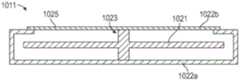
电子装置可以包括上述的本地处理和数据模块70。如上结合图3A-3D所述,本地处理和数据模块70可以包括第一壳体1300(其可以类似于壳体100)和第二壳体1301,其与第一壳体1300间隔有间隙1367。如本文所解释的,一个或多个电子装置(例如,处理器)可设置在至少部分由第一壳体1301限定的第一隔间中。一个或多个其他电子装置(例如,一个或多个电池、一个或多个处理器等)可设置在至少部分由第二壳体1302限定的第二隔间中。The electronic device may include the local processing and
在各种实施例中,可以期望在高速(例如,中央处理和/或图形处理单元的高速)下操作电子装置,同时也为电子装置的电源(例如,电池)充电。本文公开的电池可以是任何合适类型的电池,包括例如锂离子电池。然而,在高速(和相应的高温)下操作处理器,同时对电池进行充电和/或放电可能是一项挑战。例如,在一些实施例中,处理器可以在减速(throttling)回之前(例如,在开始动态频率缩放或减速之前)操作高达约95℃。处理器操作的这样的高温可能超过有效电池使用的最大温度阈值(例如,在一些实施例中,其可以在或接近45℃)。因此,在使用电子装置期间(例如,在处理器的高速操作期间),由于高速操作处理器而引起的温升可以降低快速有效地为电池充电的能力。应当理解,处理器和电池的工作温度是示意性的,并且处理器和电池可以在各种温度下操作。In various embodiments, it may be desirable to operate the electronic device at a high speed (eg, that of a central processing and/or graphics processing unit) while also charging the electronic device's power source (eg, a battery). The batteries disclosed herein can be any suitable type of batteries, including, for example, lithium-ion batteries. However, operating the processor at high speeds (and correspondingly high temperatures) while charging and/or discharging the battery can be a challenge. For example, in some embodiments, the processor may operate up to about 95°C before throttling back (eg, before starting dynamic frequency scaling or throttling). Such high temperatures at which the processor operates may exceed the maximum temperature threshold for effective battery usage (eg, in some embodiments, it may be at or near 45°C). Thus, during use of the electronic device (eg, during high-speed operation of the processor), temperature rise due to high-speed operation of the processor may reduce the ability to charge the battery quickly and efficiently. It should be understood that the operating temperatures of the processor and battery are exemplary and that the processor and battery may operate at various temperatures.
相应地,本文公开的各种实施例利用结合连接部分1365的第一和第二壳体1300、1301来热分离壳体1300、1301的隔间。例如,处理器可以设置在第一壳体1300的第一隔间中,并且可以在高速并且因此在高温下操作。电池可以设置在第二壳体1301的第二隔间中,并且可以与装置的其他部件电通信,例如与第一壳体1300中的处理器电通信。在一些实施例中,一个或多个处理元件可以设置在第一壳体1300中,一个或多个其他处理元件可以设置在第二壳体1301中。在一些实施例中,两个壳体1300、1301中的处理元件可用于控制系统的操作。Accordingly, various embodiments disclosed herein utilize the first and
在一些实施例中,连接部分1365可以包括通道1319,其可以类似于上述通道119。在一些实施例中,连接部分1365可以包括分隔第一和第二壳体1300、1301的空气或热间隙。空气隙的相对较低热导率(和较高的热绝缘性能)可用于热分离第一壳体1300中的处理器和第二壳体1301中的电池。在一些实施例中,一个或多个连接器或线可以通过通道119来将第一壳体1300中的处理器与第二壳体1301的电池电连接。还可以在第一和/或第二壳体1300、1301中提供附加部件。因此,有益地,由连接部分1365提供的热间隙可以减少或基本上防止热量从第一壳体1300中的处理器传递到第二壳体1301中的电池。因此,处理器可以在相对较高的速度和温度下工作,同时将电池保持在足够低的温度,以便在处理器的操作期间能够充电。相比之下,在单个隔间或外壳内提供电池和处理器可能无法在电池和处理器之间提供足够的热分离。In some embodiments, the connecting
在所示的实施例中,连接部分1365包括空气间隙,以在第一和第二壳体1300、1301之间提供热绝缘。在其它实施例中,可在连接部分1365中提供其它低热导材料(例如绝缘体或介质)。例如,在一些实施例中,可以在连接部分1365中提供热绝缘聚合物(例如,灌封化合物或密封剂)。在一些实施例中,由第一和第二壳体1300、1301限定的第一和第二隔间也可以填充气体(例如,空气)。在其他实施例中,电子装置(例如处理器、电池等)也可以封装或以其他方式封装在另一种绝缘材料(例如聚合物或介质)中。In the illustrated embodiment, the connecting
此外,如图13E-F所示,第一和第二壳体1300、1301可以由间隙1367(例如,在与连接部分1365隔开或低于连接部分1365的位置处)隔开,间隙宽度G如图13E所示,其可类似于或大体上与设置在第一和第二壳体1300、1301之间的连接部分1365所限定的宽度或间隙相同。间隙1367(例如,壳体1300、1301之间的空气隙)可以在第一和第二壳体1300、1301之间提供改进的热分离。在一些实施例中,第一和第二壳体1300、1301内的隔间之间的大部分空间可以填充空气或气体。例如,在一些实施例中,通道1319可以填充有气体,并且壳体1300、1301的外部部分之间的间隙1367可以包括诸如空气的气体。如图所示,通道1319可以具有小于第一壳体1300的第一隔室的横截面积(和/或小于第二壳体1301的第二隔间的横截面积)的侧截面积,其沿平行于第一隔室的最大尺寸的方向截取。13E-F, the first and
壳体1300、1301可以包括设置在间隙1367内的夹子1366。夹子1366可以包括从第一和第二壳体1300、1301延伸的突起。夹子1366可以改善模块70的佩戴性,例如,在用户的皮带或其他衣物附件上)。在一些实施例中,连接部分1365(例如,通道1319)和/或间隙1367的间隙宽度G可以在0.5mm到10mm、1mm到7mm或1mm到5mm的范围内。提供热间隙或热障(例如,空气间隙)可在壳体1300、1301之间提供足够的热分离。在一些实施例中,壳体1300、1301中的一个或两个可由具有相对较低热导率的材料构造,以进一步改善壳体1300、1301的内部腔室之间的热障。例如,在一些实施例中,与较高热导率的材料相比,可使用较低热导率的材料(例如铝或塑料)。在各种实施例中,如上文所公开的,由连接部分1365和/或间隙1367提供的热间隙仍然允许至少一些热流从第一壳体1300流向第二壳体1301。然而,本文公开的风扇组件可以减轻这种热传递,从而减少从第一壳体1300到第二壳体1301的热耗散。
图14A是电子装置的操作期间的图13A-13H中电子装置的侧视图的传热示意图1450。图14B是传热图1450的顶视示意图。如图14A和14B所示,第一壳体1300(处理器在其中设置)的温度分布可能显著高于第二壳体1301(电池在其中设置)的温度分布,这表明连接部分1365和/或间隙1367提供足够的壳体1300和1301之间的热隔离。各种实施例可有益地提供至少40℃和至少50℃等的壳体1300、1301之间的热隔离。14A is a
在本文公开的各种实施例中,我们发明人发明了用于电子装置的新的、原始的和装饰性的设计。在图15A-15H中,阴影显示轮廓和虚线用于说明目的,不构成所要求保护的设计的一部分。图15A是根据本设计的一个实施例的电子装置的示意性左后透视图。图15B是图15A的电子装置的右前前透视图。图15C是图15A-15B的电子装置的示意性前平面视图。图15D是图15A-15C的电子装置的示意性后平面视图。图15E是图15A-15C的电子装置的示意性右侧视图。15A-15D。图15F是图15A-15E中电子装置的示意左侧视图。图15G是图15A-15F中电子装置的示意顶视图。图15H是图15A-15G中电子装置的示意底部平面视图。各种实施例相应地涉及用于电子装置的装饰性设计,如本文所示和描述,至少包括在图15A-15H中。In various embodiments disclosed herein, our inventors have invented new, original and decorative designs for electronic devices. In Figures 15A-15H, hatched outlines and dashed lines are for illustrative purposes and do not form part of the claimed design. 15A is a schematic left rear perspective view of an electronic device according to one embodiment of the present design. 15B is a front right front perspective view of the electronic device of FIG. 15A. Figure 15C is a schematic front plan view of the electronic device of Figures 15A-15B. Figure 15D is a schematic rear plan view of the electronic device of Figures 15A-15C. Figure 15E is a schematic right side view of the electronic device of Figures 15A-15C. 15A-15D. Figure 15F is a schematic left side view of the electronic device of Figures 15A-15E. Figure 15G is a schematic top view of the electronic device of Figures 15A-15F. Figure 15H is a schematic bottom plan view of the electronic device of Figures 15A-15G. Various embodiments accordingly relate to decorative designs for electronic devices, as shown and described herein, including at least in Figures 15A-15H.
实例实施例Example embodiment
实施例1:一种电子装置,包括:Embodiment 1 : an electronic device, comprising:
外壳,包括:housing, including:
第一隔间,其中设置有第一电子部件;a first compartment in which a first electronic component is disposed;
第二隔间,其中设置有第二电子部件,第一和第二电子部件中的一者或两者与电子装置的另一个部件电通信;以及a second compartment in which a second electronic component is disposed, one or both of the first and second electronic components in electrical communication with the other component of the electronic device; and
在第一和第二隔间之间延伸的连接部分,a connecting portion extending between the first and second compartments,
其中,第一隔间与第二隔间在与连接部间隔开的位置处被一间隙分离,以在第一和第二电子部件之间提供热分离。Wherein, the first compartment and the second compartment are separated by a gap at a location spaced from the connection portion to provide thermal separation between the first and second electronic components.
实施例2:实施例1的电子装置,其中第一电子部件包括处理器。Embodiment 2 : The electronic device of Embodiment 1, wherein the first electronic component includes a processor.
实施例3:实施例1至2中任一实施例的电子装置,其中第二电子部件包括电源。Embodiment 3 : The electronic device of any of Embodiments 1-2, wherein the second electronic component includes a power source.
实施例4:实施例3的电子装置,其中电源包括电池。Embodiment 4 : The electronic device of Embodiment 3, wherein the power source comprises a battery.
实施例5:实施例1至4中任一实施例的电子装置,其中第一隔间、第二隔间和连接部分填充有气体。Embodiment 5 : The electronic device of any one of Embodiments 1 to 4, wherein the first compartment, the second compartment, and the connecting portion are filled with gas.
实施例6:实施例1至5中任一实施例的电子装置,其中连接部分包括第一和第二隔间之间的通道。Embodiment 6 : The electronic device of any one of Embodiments 1 to 5, wherein the connecting portion includes a channel between the first and second compartments.
实施例7:实施例6的电子装置,其中该通道具有侧截面积,该侧截面积小于沿平行于第一隔间的最大尺寸的方向截取的第一隔间的截面面积。Embodiment 7 : The electronic device of
实施例8:实施例1至7中任一实施例的电子装置,其中电子装置包括增强现实装置。Embodiment 8 : The electronic device of any one of Embodiments 1 to 7, wherein the electronic device comprises an augmented reality device.
实施例9:实施例8的电子装置,还包括连接器,该连接器被配置成连接到将由用户佩戴的头盔。Embodiment 9 : The electronic device of Embodiment 8, further comprising a connector configured to connect to a helmet to be worn by a user.
实施例10:实施例1至9中任一实施例的电子装置,其中第一电子部件与第二电子部件电通信。Embodiment 10 : The electronic device of any of Embodiments 1-9, wherein the first electronic component is in electrical communication with the second electronic component.
实施例11:实施例1至10中任何一个的电子装置,还包括设置在第一和第二隔间之间的间隙中的夹子。Embodiment 11 : The electronic device of any one of Embodiments 1 to 10, further comprising a clip disposed in the gap between the first and second compartments.
实施例12:一种便携式电子装置,包括:Embodiment 12 : a portable electronic device, comprising:
外壳;shell;
设置在外壳中的电池,该电池为便携式电子装置的至少一部分供电;a battery disposed in the housing that powers at least a portion of the portable electronic device;
用于操作便携式电子装置的电子部件,其设置在外壳中;An electronic component for operating a portable electronic device, which is provided in a housing;
热缓解组件,包括框架组件,包括:Thermal mitigation components, including frame components, including:
轴组件,具有第一端和与第一端相对的第二端,第一和第二端由框架组件支撑;a shaft assembly having a first end and a second end opposite the first end, the first and second ends being supported by the frame assembly;
叶轮,具有与毂耦合的风扇叶片,该毂与轴组件耦合,以便在外壳内围绕轴组件的纵向轴旋转;An impeller having fan blades coupled to a hub coupled to the shaft assembly for rotation within the housing about a longitudinal axis of the shaft assembly;
其中,通过轴组件的第二端部处的框架组件来控制横向于轴组件的纵向轴的载荷;wherein the load transverse to the longitudinal axis of the shaft assembly is controlled by the frame assembly at the second end of the shaft assembly;
其中,该热缓解组件除去从电池和电子部件中的一者或两者产生的热。Among other things, the thermal mitigation assembly removes heat generated from one or both of the battery and the electronic components.
实施例13:实施例12的电源组件,其中所述外壳包括第一壳体和第二壳体,电子部件和热缓解组件被设置在第一壳体中以及电池被设置在第二壳体中。Embodiment 13 : The power supply assembly of Embodiment 12, wherein the housing includes a first housing and a second housing, the electronic components and the thermal mitigation assembly are disposed in the first housing and the battery is disposed in the second housing .
实施例14:实施例12或13的电源组件,其中轴组件包括连接到框架组件的第一框架的第一轴部分和连接到框架组件的第二框架的第二轴部分,第一和第二轴部分至少部分地设置在毂的相对侧上。Embodiment 14 : The power supply assembly of Embodiment 12 or 13, wherein the shaft assembly includes a first shaft portion connected to a first frame of the frame assembly and a second shaft portion connected to a second frame of the frame assembly, the first and second Shaft portions are disposed at least partially on opposite sides of the hub.
实施例15:一种风扇组件,包括:Embodiment 15 : a fan assembly, comprising:
第一支撑框架;the first support frame;
轴组件,具有与第一支撑框架耦合的第一端和远离第一端设置的第二端;a shaft assembly having a first end coupled to the first support frame and a second end disposed remote from the first end;
第二支撑框架,与所述第一支撑框架耦合并设置在轴组件的第二端处或其上方;a second support frame coupled to the first support frame and disposed at or above the second end of the shaft assembly;
具有与毂耦合的风扇叶片的叶轮,该毂被设置在轴组件上,用于围绕纵向轴在第一和第二支撑框架之间旋转;an impeller having fan blades coupled to a hub disposed on the shaft assembly for rotation about a longitudinal axis between the first and second support frames;
其中,轴组件上的横向载荷通过第一和第二支撑框架控制。Therein, lateral loads on the shaft assembly are controlled by the first and second support frames.
实施例16:实施例15的风扇组件,其中第二支撑框架包括围绕在轴组件的第一和第二端之间延伸的纵向轴设置的空气流开口。Embodiment 16 : The fan assembly of Embodiment 15, wherein the second support frame includes air flow openings disposed about a longitudinal shaft extending between the first and second ends of the shaft assembly.
实施例17:实施例16的风扇组件,还包括与轴组件的第二端耦合的轴支撑,轴支撑跨空气流开口刚性地附接到第二支撑框架。Embodiment 17 : The fan assembly of Embodiment 16, further comprising a shaft support coupled to the second end of the shaft assembly, the shaft support rigidly attached to the second support frame across the air flow opening.
实施例18:实施例17的风扇组件,其中轴支撑被支撑在第二支撑框架的各第一和第二部分,各第一和第二部分围绕空气流开口的周边间隔开。Embodiment 18 : The fan assembly of Embodiment 17, wherein the shaft support is supported on respective first and second portions of the second support frame, the respective first and second portions being spaced about a perimeter of the air flow opening.
实施例19:实施例18的风扇组件,其中第二支撑框架的第一部分通常相对于第二支撑框架的第二部分位于空气流开口的相对侧上。Embodiment 19 : The fan assembly of Embodiment 18, wherein the first portion of the second support frame is located generally on an opposite side of the air flow opening relative to the second portion of the second support frame.
实施例20:实施例17至19中的任一个的风扇组件,其中,轴支撑被设置在对应于当叶轮操作时的最大空气流的空气流开口的旋转位置。Embodiment 20 : The fan assembly of any one of Embodiments 17 to 19, wherein the shaft support is positioned in a rotational position corresponding to the air flow opening for maximum air flow when the impeller is operating.
实施例21:实施例17至20中任何一个的风扇组件,其中轴支撑包括在其第一和第二端之间的伸长构件,伸长构件具有翼型形状。Embodiment 21 : The fan assembly of any one of Embodiments 17 to 20, wherein the shaft support includes an elongated member between its first and second ends, the elongated member having an airfoil shape.
实施例22:实施例17至21中任何一个的风扇组件,其中轴支撑包括在其第一和第二端之间的伸长构件,该伸长构件具有沿其长度变化的宽度。Embodiment 22 : The fan assembly of any one of Embodiments 17 to 21, wherein the shaft support includes an elongated member between its first and second ends, the elongated member having a width that varies along its length.
实施例23:实施例17至22中任一实施例的风扇组件,其中轴支撑包括在其第一和第二端之间的伸长构件,该伸长构件具有沿其长度变化的厚度。Embodiment 23 : The fan assembly of any of Embodiments 17-22, wherein the shaft support includes an elongated member between its first and second ends, the elongated member having a thickness that varies along its length.
实施例24:实施例15至23中任一实施例的风扇组件,其中轴组件包括旋转固定至第一支撑框架的第一轴部分和旋转固定至叶轮的第二部分,第二部分在轴组件的第一轴部分的自由端上是可旋转的。Embodiment 24 : The fan assembly of any one of Embodiments 15 to 23, wherein the shaft assembly includes a first shaft portion rotatably secured to the first support frame and a second portion rotatably secured to the impeller, the second portion being in the shaft assembly The free end of the first shaft portion is rotatable.
实施例25:实施例15至24中任一实施例的风扇组件,其中轴组件包括伸长构件,其第一端设置在叶轮的第一侧,第二端设置在叶轮的第二侧,第二侧与第一侧相对。Embodiment 25 : The fan assembly of any one of Embodiments 15 to 24, wherein the shaft assembly includes an elongated member with a first end disposed on a first side of the impeller, a second end disposed on a second side of the impeller, The second side is opposite to the first side.
实施例26:实施例25的风扇组件,还包括与第二支撑框架耦合的凹面构件,其配置为旋转地支撑伸长构件的第二端。Embodiment 26 : The fan assembly of Embodiment 25, further comprising a concave member coupled with the second support frame and configured to rotatably support the second end of the elongate member.
实施例27:实施例26的风扇组件,还包括与第一支撑框架耦合并配置成旋转支撑伸长构件的第一端的附加凹面构件。Embodiment 27 : The fan assembly of Embodiment 26, further comprising an additional concave member coupled to the first support frame and configured to rotatably support the first end of the elongate member.
实施例28:实施例16至27中的任一个的风扇组件,其中风扇组件的空气流路径在围绕纵向轴设置的空气流开口和围绕不平行于纵向轴的轴设置的具有面的第二空气流开口之间延伸。Embodiment 28 : The fan assembly of any one of Embodiments 16 to 27, wherein the air flow path of the fan assembly is at an air flow opening disposed about a longitudinal axis and a second air having a face disposed about an axis that is not parallel to the longitudinal axis extending between the flow openings.
实施例29:实施例28的风扇组件,其中,不平行于纵向轴的轴通常垂直于纵向轴并沿叶轮的径向延伸轴被设置。Embodiment 29 : The fan assembly of Embodiment 28, wherein the axis that is not parallel to the longitudinal axis is generally perpendicular to the longitudinal axis and is disposed along the radially extending axis of the impeller.
实施例30:一种风扇组件,包括:Embodiment 30: A fan assembly, comprising:
在第一端处支撑轴组件的外壳,该轴具有与第一端相对的第二端;supporting a housing of the shaft assembly at a first end, the shaft having a second end opposite the first end;
叶轮,其具有与毂耦合的风扇叶片,所述毂与所述轴耦合,以便围绕纵向轴在外壳内旋转;An impeller having fan blades coupled to a hub coupled to the shaft for rotation within the housing about a longitudinal axis;
其中,轴组件上的横向载荷由轴组件的第二端处的外壳控制。Therein, the lateral load on the shaft assembly is controlled by the housing at the second end of the shaft assembly.
实施例31:一种风扇组件,包括:Embodiment 31 : A fan assembly, comprising:
外壳,包括轴支撑和由轴支撑所支撑的轴组件;a housing, including a shaft support and a shaft assembly supported by the shaft support;
叶轮,设置在外壳中并与轴组件耦合,叶轮被配置为围绕轴组件的纵向轴旋转;An impeller disposed in the housing and coupled to the shaft assembly, the impeller configured to rotate about a longitudinal axis of the shaft assembly;
围绕纵向轴设置的第一空气流开口;a first air flow opening disposed about the longitudinal axis;
第二空气流开口,其具有面,围绕相对于纵向轴的非平行轴设置;a second air flow opening having a face disposed about a non-parallel axis relative to the longitudinal axis;
风扇组件的气流路径,在第一空气流开口和第二空气流开口之间延伸,an air flow path of the fan assembly extending between the first air flow opening and the second air flow opening,
其中,该轴支撑包括跨第一空气流开口的至少一部分延伸的伸长构件,该伸长构件以相对于非平行轴的角度而被成角度地跨第一空气流开口设置,该角度允许通过第一空气流开口的至少局部最大空气流。wherein the shaft support includes an elongate member extending across at least a portion of the first air flow opening, the elongate member being angled across the first air flow opening at an angle relative to a non-parallel axis that allows passage of At least local maximum air flow of the first air flow opening.
实施例32:实施例31的风扇组件,其中相对于非平行轴的角度是锐角。Embodiment 32 : The fan assembly of Embodiment 31, wherein the angle relative to the non-parallel axis is an acute angle.
实施例33:实施例32的风扇组件,其中相对于非平行轴的角度在-45°至45°的范围内。Embodiment 33 : The fan assembly of Embodiment 32, wherein the angle relative to the non-parallel axis is in the range of -45° to 45°.
实施例34:实施例33的风扇组件,其中相对于非平行轴的角度在-30°至30°的范围内。Embodiment 34 : The fan assembly of Embodiment 33, wherein the angle relative to the non-parallel axis is in the range of -30° to 30°.
实施例35:一种制造风扇组件的方法,该方法包括:Embodiment 35 : A method of manufacturing a fan assembly, the method comprising:
提供风扇组件,该风扇组件包括:A fan assembly is provided that includes:
外壳;shell;
叶轮,设置在外壳中并与轴组件耦合,叶轮被配置为围绕轴组件的纵向轴旋转;An impeller disposed in the housing and coupled to the shaft assembly, the impeller configured to rotate about a longitudinal axis of the shaft assembly;
围绕纵向轴设置的第一空气流开口;a first air flow opening disposed about the longitudinal axis;
具有面的第二空气流开口,围绕相对于纵向轴的非平行轴设置,其中风扇组件的空气流路径在第一空气流开口和第二空气流开口之间延伸;a second air flow opening having a face disposed about a non-parallel axis relative to the longitudinal axis, wherein the air flow path of the fan assembly extends between the first air flow opening and the second air flow opening;
计算通过风扇组件的空气流分布;以及Calculate the distribution of air flow through the fan assembly; and
基于该计算,提供轴支撑以支撑轴组件的端部,该轴支撑包括跨第一空气流开口的至少一部分延伸的伸长构件。Based on the calculation, a shaft support is provided to support the end of the shaft assembly, the shaft support including an elongate member extending across at least a portion of the first air flow opening.
实施例36:实施例35的方法,进一步包括基于该计算,以相对于非平行轴的角度至少部分地跨第一空气流开口成角度地设置该伸长构件,该角度允许通过第一空气流开口的至少局部最大空气流。Embodiment 36 : The method of Embodiment 35, further comprising, based on the calculation, angling the elongated member at least partially across the first air flow opening at an angle relative to the non-parallel axis that allows passage of the first air flow At least local maximum air flow of the opening.
实施例37:实施例36的方法,其中成角度设置包括以锐角相对于非平行轴定向该角度。Embodiment 37 : The method of Embodiment 36, wherein the angling comprises orienting the angle at an acute angle relative to a non-parallel axis.
实施例38:实施例37的方法,其中成角度设置包括相对于非平行轴在-45°至45°范围内定向该角度。Embodiment 38 : The method of Embodiment 37, wherein the angling comprises orienting the angle relative to the non-parallel axis in the range of -45° to 45°.
实施例39:实施例38的方法,其中成角度设置包括相对于非平行轴在-30°至30°范围内定向角度。Embodiment 39 : The method of Embodiment 38, wherein the angled disposition comprises orienting the angle within a range of -30° to 30° with respect to the non-parallel axis.
附加考虑Additional Considerations
这里描述和/或附图中描述的任何过程、方法和算法可以被体现在由一个或多个物理计算系统、硬件计算机处理器、特定于应用的电路执行的代码模块中,并且可以完全或部分自动化,和/或体现在配置成执行特定计算机指令的电子硬件中。例如,计算系统可以包括用特定计算机指令编程的通用计算机(例如服务器)或专用计算机、专用电路等。代码模块可以编译并链接到可执行程序中,也可以安装在动态链接库中,或者可以用解释性编程语言编写。在一些实现中,特定的操作和方法可以由特定于给定功能的电路来执行。Any of the processes, methods and algorithms described herein and/or in the accompanying figures may be embodied in code modules executed by one or more physical computing systems, hardware computer processors, application-specific circuits, and may be implemented in whole or in part automated, and/or embodied in electronic hardware configured to execute specific computer instructions. For example, a computing system may include a general purpose computer (eg, a server) or a special purpose computer, special purpose circuits, etc. programmed with specific computer instructions. Code modules can be compiled and linked into an executable program, installed in a dynamic link library, or written in an interpreted programming language. In some implementations, certain operations and methods may be performed by circuitry specific to a given function.
此外,本公开的功能的某些实现在数学上、计算上或技术上足够复杂,因此可能需要特定于应用程序的硬件或一个或多个物理计算设备(利用适当的专用可执行指令)来执行该功能,例如,由于所涉及的计算的量或复杂性,或者实质上实时地提供结果。例如,视频可以包括许多帧,每个帧具有数百万像素,并且需要专门编程的计算机硬件来处理视频数据,以便在商业上合理的时间量内提供所需的图像处理任务或应用。Furthermore, some implementations of the functions of the present disclosure are mathematically, computationally, or technically complex enough to require application-specific hardware or one or more physical computing devices (with appropriate special-purpose executable instructions) to perform This function, for example, may provide results in substantially real-time due to the amount or complexity of the computations involved. For example, a video may include many frames, each with millions of pixels, and require specially programmed computer hardware to process the video data in order to provide the desired image processing task or application in a commercially reasonable amount of time.
代码模块或任何类型的数据可以存储在任何类型的非暂时性计算机可读介质上,例如包括硬盘驱动器、固态存储器、随机存取存储器(RAM)、只读存储器(ROM)、光盘、易失性或非易失性存储器、相同和/或类似的组合的物理计算机存储器。方法和模块(或数据)也可以作为产生的数据信号(例如,作为载波或其他模拟或数字传播信号的一部分)在各种计算机可读传输介质(包括基于无线和基于线/缆的介质)上传输,并且可以采取多种形式(例如,作为单个或多路复用的模拟信号的一部分,或作为多个离散数字分组或帧)。所公开的过程或过程步骤的结果可以持久地或以其他方式存储在任何类型的非暂时的、有形的计算机存储中,或者可以通过计算机可读传输介质来传送。A code module or any type of data may be stored on any type of non-transitory computer readable medium including, for example, hard drives, solid state memory, random access memory (RAM), read only memory (ROM), optical disks, volatile or non-volatile memory, physical computer memory of the same and/or similar combination. The methods and modules (or data) may also be generated as data signals (eg, as part of a carrier wave or other analog or digital propagated signal) over various computer-readable transmission media, including wireless and wire/cable-based media is transmitted, and can take many forms (eg, as part of a single or multiplexed analog signal, or as multiple discrete digital packets or frames). The results of the disclosed processes or process steps may be stored persistently or otherwise in any type of non-transitory, tangible computer storage, or may be transmitted over a computer-readable transmission medium.
本文中描述和/或附图中描述的流程图中的任何过程、块、状态、步骤或功能应理解为潜在地表示代码模块、段或代码部分,其包括用于实现特定功能或过程中的步骤的一个或多个可执行指令(例如逻辑或算术指令)。各种过程、块、状态、步骤或功能可以组合、重新排列、添加、删除、修改或以其他方式从本文提供的说明性示例中改变。在一些实施例中,附加的或不同的计算系统或代码模块可以执行本文描述的部分或全部功能。本文所描述的方法和过程也不限于任何特定顺序,并且与之相关的块、步骤或状态可以在适当的其它顺序中执行,例如,以串行、并行或其它方式。任务或事件可以添加到所公开的示例实施例中或从中移除。此外,本文描述的实现中的各种系统部件的分离是为了说明目的,不应理解为在所有实现中都需要这种分离。应当理解,所描述的程序部件、方法和系统通常可以集成在单一计算机产品中,或者打包成多个计算机产品。许多实现变体是可能的。Any process, block, state, step or function in the flowcharts described herein and/or in the accompanying drawings should be understood to potentially represent a module, segment or portion of code, including means for implementing the particular function or process. One or more executable instructions (eg, logical or arithmetic instructions) for a step. Various processes, blocks, states, steps or functions may be combined, rearranged, added, deleted, modified or otherwise changed from the illustrative examples provided herein. In some embodiments, additional or different computing systems or code modules may perform some or all of the functions described herein. The methods and processes described herein are also not limited to any particular order, and the blocks, steps or states associated therewith may be performed in suitable other orders, eg, serially, in parallel, or otherwise. Tasks or events may be added to or removed from the disclosed example embodiments. Furthermore, the separation of various system components in the implementations described herein is for illustrative purposes and should not be construed as requiring such separation in all implementations. It should be understood that the described program components, methods and systems may generally be integrated in a single computer product or packaged into multiple computer products. Many implementation variants are possible.
过程、方法和系统可以在网络(或分布式)计算环境中实现。网络环境包括企业范围的计算机网络、内部网、局域网(LAN)、广域网(WAN)、个人区域网(PAN)、云计算网络、众包计算网络、因特网和万维网。网络可以是有线或无线网络或任何其他类型的通信网络。The processes, methods, and systems can be implemented in network (or distributed) computing environments. Networking environments include enterprise-wide computer networks, intranets, local area networks (LANs), wide area networks (WANs), personal area networks (PANs), cloud computing networks, crowdsourced computing networks, the Internet, and the World Wide Web. The network may be a wired or wireless network or any other type of communication network.
本发明包括可使用主题装置执行的方法。该方法可包括提供这样的适当装置的动作。此类规定可由最终用户执行。换言之,“提供”动作仅要求最终用户获得、访问、接近、定位、设置、激活、上电或以其他方式提供主题方法中所需的装置。这里所述的方法可以以逻辑上可能的列举事件的任何顺序以及以列举的事件顺序来执行。The present invention includes methods executable using the subject apparatus. The method may include the act of providing such suitable means. Such provisions may be enforced by end users. In other words, the "provide" action merely requires the end user to obtain, access, access, locate, set up, activate, power on, or otherwise provide the device required in the subject method. The methods described herein may be performed in any order and in the order in which events are enumerated that are logically possible.
本公开的系统和方法各有若干创新方面,创新方面中没有单个方面单独负责或要求本公开公开的期望属性。这里描述的各种特征和过程可以彼此独立地使用,或者可以以各种方式组合。所有可能的组合和子组合都旨在落入本公开的范围。对于本领域技术人员来说,对本公开中描述的实现的各种修改可能是显而易见的,并且在不脱离本公开的精神或范围的情况下,本文定义的一般原则可以应用于其他实现。因此,权利要求不限于本文所示的实现,而是应被赋予与本公开、本文所公开的原理和新颖特性一致的最宽范围。The systems and methods of the present disclosure each have several innovative aspects, no single one of which is solely responsible for or claims the desirable attributes disclosed in the present disclosure. The various features and procedures described herein can be used independently of one another or can be combined in various ways. All possible combinations and subcombinations are intended to fall within the scope of this disclosure. Various modifications to the implementations described in this disclosure may be readily apparent to those skilled in the art, and the generic principles defined herein may be applied to other implementations without departing from the spirit or scope of this disclosure. Therefore, the claims are not to be limited to the implementations shown herein, but are to be accorded the widest scope consistent with this disclosure, the principles and novel features disclosed herein.
本说明书中在独立的实现方式的上下文中描述的某些特性也可以在单个实现方式中组合实现。相反,在单个实现方式的上下文中描述的各种特征也可以单独在多个实现方式中或在任何合适的子组合中实现。此外,尽管上述特征可以被描述为在某些组合中起作用,甚至最初是这样声称的,但是在某些情况下,可以从所声称的组合中除去来自组合的一个或多个特征,并且所声称的组合可以被指向子组合或子组合的变体。对于每个和每个实施例,没有单个特征或特征组是必要的或必不可少的。Certain features that are described in this specification in the context of separate implementations can also be implemented in combination in a single implementation. Conversely, various features that are described in the context of a single implementation can also be implemented in multiple implementations separately or in any suitable subcombination. Furthermore, although the above features may be described as functioning in certain combinations, even initially claimed, in some cases one or more features from the combination may be removed from the claimed combination and the claimed Claimed combinations can be directed to subcombinations or variants of subcombinations. No single feature or group of features is necessary or essential to each and every embodiment.
本文中使用的条件语言,例如,除其他外,“能够”、“能”、“可”、“可以”、“例如”等,除非特别地另有说明,或在所使用的上下文中以其他方式理解,通常意在传达某些实施例包括,而其他实施例不包括,某些特征、要素和/或步骤。因此,这样的条件语言一般不旨在暗示一个或多个实施例以任何方式需要特征、元素和/或步骤,或者一个或多个实施例必然包括用于在有或无作者输入或提示的情况下决定是否这些特征、要素和/或步骤在任何特定实施例中被包括或执行的逻辑。术语“包括”、“包含”、“具有”等是同义词,并且以开放的方式被包括地使用,并且不排除额外的要素、特征、动作、操作等。此外,术语“或”在其包容性意义上(而不是在其排他性意义上)被使用,因此当用于例如连接要素列表时,术语“或”意味着列表中的一个、一些或所有元素。此外,除非另有规定,否则本申请和所附权利要求中使用的条款“一”、“一个”和“该”应解释为“一个或多个”或“至少一个”。除本文明确规定外,本文中使用的所有技术和科学术语应在保持权利要求有效性的同时尽可能广泛地给出一个通常理解的含义。Conditional language used herein, eg, "could," "could," "could," "could," "eg," etc., among others, unless specifically stated otherwise, or otherwise in the context of use By way of understanding, it is generally intended to convey that certain embodiments include, while other embodiments do not, certain features, elements and/or steps. Thus, such conditional language is generally not intended to imply that one or more embodiments require features, elements, and/or steps in any way, or that one or more embodiments are necessarily included for use with or without author input or prompting Logic that determines whether these features, elements and/or steps are included or performed in any particular embodiment. The terms "comprising", "comprising", "having" and the like are synonymous and are used in an open-ended fashion and do not exclude additional elements, features, acts, operations, and the like. Furthermore, the term "or" is used in its inclusive sense (rather than in its exclusive sense), so when used, for example, to concatenate lists of elements, the term "or" means one, some or all of the elements of the list. In addition, the terms "a," "an," and "the" used in this application and the appended claims should be construed to mean "one or more" or "at least one" unless specified otherwise. Unless expressly defined herein, all technical and scientific terms used herein are to be given a commonly understood meaning as broadly as possible while maintaining claim validity.
如本文所用,提及项目列表中“的至少一个”的短语是指这些项目的任何组合,包括单个成员。例如,“A、B或C”中的“至少一个”意欲涵盖:A、B、C、A和B、A和C、B和C以及A、B和C。除非另有特别说明,诸如短语“X、Y和Z中的至少一个”之类的连接语言在通常使用的上下文中被另外的理解以表达项、术语等是X、Y或Z中的至少一个。因此,这样的连接语言通常并不意味着某些实施例要求X中的至少一个、Y中的至少一个和Z中的至少一个存在。As used herein, a phrase referring to "at least one of" in a list of items refers to any combination of those items, including individual members. For example, "at least one" of "A, B or C" is intended to encompass: A, B, C, A and B, A and C, B and C, and A, B and C. Conjunctive language such as the phrase "at least one of X, Y, and Z" is otherwise understood in the context of common use to express that the item, term, etc. is at least one of X, Y, or Z, unless specifically stated otherwise. . Thus, such a connection language generally does not imply that certain embodiments require at least one of X, at least one of Y, and at least one of Z to be present.
类似地,虽然可以在附图中以特定顺序描述操作,但是应当认识到,不需要按照所示的特定顺序或次序执行这些操作,或者不需要执行所有示出的操作,以获得期望的结果。此外,附图可以示意性地以流程图的形式描绘一个以上的示例处理。然而,未描述的其他操作可并入示意性地示出的示例方法和过程中。例如,可以在所示的任何操作之前、之后、同时或之间执行一个或多个附加操作。另外,在其他实现中,可以重新排列或重新排序操作。在某些情况下,多任务和并行处理可能是有利的。此外,不应将上述实现中的各种系统组件的分离理解为在所有实现中都需要这样的分离,并且应当理解,所描述的程序组件和系统通常可以集成在单个软件产品中或打包成多个软件产品。另外,其他实现也在以下权利要求的范围内。在某些情况下,可以按照不同的顺序执行权利要求中所述的动作,并且仍然能够获得希望的结果。Similarly, although operations may be depicted in the figures in a particular order, it should be recognized that the operations need not be performed in the particular order or sequence shown, or that all illustrated operations need be performed, to achieve desirable results. Furthermore, the figures may schematically depict one or more example processes in flowchart form. However, other operations not described may be incorporated into the example methods and processes shown schematically. For example, one or more additional operations may be performed before, after, concurrent with, or in between any operations shown. Additionally, in other implementations, operations may be rearranged or reordered. In some cases, multitasking and parallel processing may be advantageous. Furthermore, the separation of the various system components in the above-described implementations should not be construed as requiring such separation in all implementations, and it should be understood that the described program components and systems may generally be integrated in a single software product or packaged into multiple a software product. Additionally, other implementations are within the scope of the following claims. In some cases, the actions recited in the claims can be performed in a different order and still achieve desirable results.
Claims (39)
Priority Applications (1)
| Application Number | Priority Date | Filing Date | Title |
|---|---|---|---|
| CN202310648397.4ACN116666814A (en) | 2017-05-30 | 2018-05-29 | Power supply assembly with fan assembly for electronic devices |
Applications Claiming Priority (5)
| Application Number | Priority Date | Filing Date | Title |
|---|---|---|---|
| US201762512635P | 2017-05-30 | 2017-05-30 | |
| US62/512,635 | 2017-05-30 | ||
| US201862671379P | 2018-05-14 | 2018-05-14 | |
| US62/671,379 | 2018-05-14 | ||
| PCT/US2018/034948WO2018222618A1 (en) | 2017-05-30 | 2018-05-29 | Power supply assembly with fan assembly for electronic device |
Related Child Applications (1)
| Application Number | Title | Priority Date | Filing Date |
|---|---|---|---|
| CN202310648397.4ADivisionCN116666814A (en) | 2017-05-30 | 2018-05-29 | Power supply assembly with fan assembly for electronic devices |
Publications (2)
| Publication Number | Publication Date |
|---|---|
| CN110710014Atrue CN110710014A (en) | 2020-01-17 |
| CN110710014B CN110710014B (en) | 2023-06-20 |
Family
ID=64455804
Family Applications (2)
| Application Number | Title | Priority Date | Filing Date |
|---|---|---|---|
| CN202310648397.4APendingCN116666814A (en) | 2017-05-30 | 2018-05-29 | Power supply assembly with fan assembly for electronic devices |
| CN201880036283.1AActiveCN110710014B (en) | 2017-05-30 | 2018-05-29 | Power supply assembly with fan assembly for electronic devices |
Family Applications Before (1)
| Application Number | Title | Priority Date | Filing Date |
|---|---|---|---|
| CN202310648397.4APendingCN116666814A (en) | 2017-05-30 | 2018-05-29 | Power supply assembly with fan assembly for electronic devices |
Country Status (9)
| Country | Link |
|---|---|
| US (4) | US10871806B2 (en) |
| EP (2) | EP3631874B1 (en) |
| JP (3) | JP7319927B2 (en) |
| KR (3) | KR20240069815A (en) |
| CN (2) | CN116666814A (en) |
| AU (2) | AU2018277530B2 (en) |
| CA (1) | CA3059984C (en) |
| IL (3) | IL311011A (en) |
| WO (1) | WO2018222618A1 (en) |
Families Citing this family (22)
| Publication number | Priority date | Publication date | Assignee | Title |
|---|---|---|---|---|
| CN112925100B (en) | 2014-09-29 | 2023-10-31 | 奇跃公司 | Optical system |
| AU2017264780B2 (en) | 2016-05-12 | 2022-05-12 | Magic Leap, Inc. | Distributed light manipulation over imaging waveguide |
| EP3542241B1 (en) | 2016-11-16 | 2021-09-01 | Magic Leap, Inc. | Thermal management systems for wearable components |
| WO2018222618A1 (en) | 2017-05-30 | 2018-12-06 | Magic Leap, Inc. | Power supply assembly with fan assembly for electronic device |
| CN110998099B (en) | 2017-07-28 | 2025-06-10 | 奇跃公司 | Fan assembly for displaying images |
| US12099386B2 (en) | 2018-07-24 | 2024-09-24 | Magic Leap, Inc. | Thermal management system for electronic device |
| CN113168212B (en) | 2018-12-13 | 2024-12-03 | 惠普发展公司,有限责任合伙企业 | Computing device with integrated and isolated liquid cooling |
| US10859326B2 (en)* | 2019-01-09 | 2020-12-08 | Dell Products L.P. | Fin stack for processor cooling |
| CN114174463A (en) | 2019-05-28 | 2022-03-11 | 奇跃公司 | Thermal management system for portable electronic devices |
| TWI695669B (en)* | 2019-06-21 | 2020-06-01 | 仁寶電腦工業股份有限公司 | Thermal module |
| CN110716315A (en)* | 2019-11-29 | 2020-01-21 | 北京枭龙防务科技有限公司 | Intelligent glasses |
| USD961915S1 (en) | 2020-02-05 | 2022-08-30 | Magic Leap, Inc. | Holder with device |
| USD933358S1 (en) | 2020-02-05 | 2021-10-19 | Magic Leap, Inc. | Belt with device holders |
| USD986245S1 (en) | 2020-02-05 | 2023-05-16 | Magic Leap, Inc. | Holster with retractable device |
| USD961914S1 (en) | 2020-02-05 | 2022-08-30 | Magic Leap, Inc. | Holster for retractable device |
| USD998324S1 (en) | 2020-02-05 | 2023-09-12 | Magic Leap, Inc. | Belt assembly with holders and devices |
| USD975716S1 (en) | 2020-02-05 | 2023-01-17 | Magic Leap, Inc. | Holder for controller |
| US11512711B2 (en)* | 2020-09-18 | 2022-11-29 | Asia Vital Components Co., Ltd. | Centrifugal fan frame body structure |
| KR20240018607A (en)* | 2021-06-09 | 2024-02-13 | 스냅 인코포레이티드 | Devices with dynamic transcode throttling |
| US11483569B1 (en)* | 2021-06-09 | 2022-10-25 | Snap Inc. | Device with dynamic transcode throttling |
| EP4571392A1 (en)* | 2022-09-13 | 2025-06-18 | Samsung Electronics Co., Ltd. | Electronic device and method for dissipating heat from plurality of heat sources |
| CN219754832U (en)* | 2023-03-14 | 2023-09-26 | 台达电子工业股份有限公司 | Centrifugal fan module |
Citations (17)
| Publication number | Priority date | Publication date | Assignee | Title |
|---|---|---|---|---|
| US5577888A (en)* | 1995-06-23 | 1996-11-26 | Siemens Electric Limited | High efficiency, low-noise, axial fan assembly |
| JP2001308999A (en)* | 2000-04-20 | 2001-11-02 | Kenwood Corp | Mobile wireless phone |
| JP2002345293A (en)* | 2001-05-17 | 2002-11-29 | Toa Corp | Controller and method for controlling fan |
| US20050104459A1 (en)* | 2003-11-17 | 2005-05-19 | Emerson Electric Co. | Low noise ventilation system for electric motor |
| WO2005099663A2 (en)* | 2004-04-14 | 2005-10-27 | University Of Southern California | Scent delivery device and method of simulating scent in a virtual environment |
| JP2007194872A (en)* | 2006-01-18 | 2007-08-02 | Casio Hitachi Mobile Communications Co Ltd | Folding type electronic apparatus |
| JP2009071516A (en)* | 2007-09-12 | 2009-04-02 | Olympus Imaging Corp | Electronic camera |
| US20120069514A1 (en)* | 2010-09-20 | 2012-03-22 | Ross Peter G | System with air flow under data storage devices |
| CN202372910U (en)* | 2011-09-28 | 2012-08-08 | 深圳市顶星数码网络技术有限公司 | Radiating device |
| JP2012168446A (en)* | 2011-02-16 | 2012-09-06 | Nikon Corp | External device |
| CN102749975A (en)* | 2011-03-04 | 2012-10-24 | 苹果公司 | Compact fan assembly with thrust bearing |
| CN104566757A (en)* | 2014-12-26 | 2015-04-29 | 必宜(天津)科技有限公司 | Window sill-type ventilation cleaning device |
| US20150351280A1 (en)* | 2014-05-29 | 2015-12-03 | Arris Enterprises, Inc. | Pivotable Fan Assembly and Associated Systems |
| CN105190450A (en)* | 2013-03-08 | 2015-12-23 | 通腾科技股份有限公司 | Fitness watch case |
| WO2016170717A1 (en)* | 2015-04-23 | 2016-10-27 | ソニー株式会社 | Wearable display, information processing system, and control method |
| CN106358419A (en)* | 2015-07-16 | 2017-01-25 | 中兴通讯股份有限公司 | Modularized data center |
| CN109863533A (en)* | 2016-08-22 | 2019-06-07 | 奇跃公司 | Virtual, Augmented and Mixed Reality Systems and Methods |
Family Cites Families (142)
| Publication number | Priority date | Publication date | Assignee | Title |
|---|---|---|---|---|
| US1921218A (en)* | 1932-02-29 | 1933-08-08 | Clyde W Colby | Fan |
| US2853539A (en) | 1952-10-14 | 1958-09-23 | Ultra Electric Inc | Enclosure for electronic apparatus |
| US4385911A (en)* | 1982-01-22 | 1983-05-31 | Ronco Teleproducts, Inc. | Air filtering device |
| US5082422A (en) | 1991-06-10 | 1992-01-21 | Wang Sui Mu | Illuminative fan |
| US5291560A (en) | 1991-07-15 | 1994-03-01 | Iri Scan Incorporated | Biometric personal identification system based on iris analysis |
| US6222525B1 (en) | 1992-03-05 | 2001-04-24 | Brad A. Armstrong | Image controllers with sheet connected sensors |
| US5610678A (en)* | 1993-12-30 | 1997-03-11 | Canon Kabushiki Kaisha | Camera including camera body and independent optical viewfinder |
| US5670988A (en) | 1995-09-05 | 1997-09-23 | Interlink Electronics, Inc. | Trigger operated electronic device |
| JP3348576B2 (en) | 1995-11-10 | 2002-11-20 | ソニー株式会社 | Temperature detecting device, semiconductor element mounting the same, and autofocus system using the same |
| JPH09230321A (en) | 1996-02-20 | 1997-09-05 | Denso Corp | Color liquid crystal display device |
| US5993060A (en) | 1997-01-14 | 1999-11-30 | Citizen Watch Co., Ltd. | Temperature sensor and method of adjusting the same |
| US6037876A (en) | 1998-04-23 | 2000-03-14 | Limelite Industries, Inc. | Lighted message fan |
| US6594630B1 (en) | 1999-11-19 | 2003-07-15 | Voice Signal Technologies, Inc. | Voice-activated control for electrical device |
| US6349864B1 (en)* | 1999-12-23 | 2002-02-26 | Hsin-Kuo Lee | Mechanical arrangement for promoting portable computer's adaptability to application |
| JP3070325U (en) | 2000-01-17 | 2000-07-28 | 元山科技工業股▲分▼有限公司 | Axial fan shaft support structure |
| US6567269B2 (en)* | 2001-04-23 | 2003-05-20 | Hewlett-Packard Development Company, L.P. | Computer system having removable processor and modular thermal unit |
| US6561762B1 (en)* | 2001-11-14 | 2003-05-13 | Sunonwealth Electric Machine Industry Co., Ltd. | Housing structure of a fan |
| JP2003216071A (en) | 2002-01-21 | 2003-07-30 | Noritsu Koki Co Ltd | Rotary type display device |
| JP2003244296A (en) | 2002-02-20 | 2003-08-29 | Seiko Epson Corp | Mobile phones and personal computers |
| US6805536B2 (en)* | 2003-01-28 | 2004-10-19 | Averatec Inc. | Heat dissipation fan |
| US8118674B2 (en) | 2003-03-27 | 2012-02-21 | Wms Gaming Inc. | Gaming machine having a 3D display |
| US20040223299A1 (en) | 2003-05-07 | 2004-11-11 | Prosenjit Ghosh | Display cooling |
| TWM240488U (en)* | 2003-07-02 | 2004-08-11 | Datech Technology Co Ltd | Fan with guiding rib in vent |
| TW200517815A (en) | 2003-11-28 | 2005-06-01 | Soltek Comp Inc | Heat sink device of computer case |
| JP2005252732A (en)* | 2004-03-04 | 2005-09-15 | Olympus Corp | Imaging device |
| JP2005308980A (en) | 2004-04-20 | 2005-11-04 | Seiko Epson Corp | Rotary display device |
| US20070247832A1 (en) | 2004-04-23 | 2007-10-25 | Barker Dale E | Fan with Bladers and Method for Displaying Illuminated Pictoral Elements |
| USD514570S1 (en) | 2004-06-24 | 2006-02-07 | Microsoft Corporation | Region of a fingerprint scanning device with an illuminated ring |
| US8411108B2 (en) | 2004-07-21 | 2013-04-02 | Lightning Wheels, Llc | Rotational display system |
| US7142423B2 (en)* | 2004-10-26 | 2006-11-28 | Comarco Wireless Technologies, Inc. | Power adapter with fan assembly |
| US20060109200A1 (en) | 2004-11-22 | 2006-05-25 | Alden Ray M | Rotating cylinder multi-program and auto-stereoscopic 3D display and camera |
| US7250954B2 (en) | 2004-12-16 | 2007-07-31 | Palo Alto Research Center, Incorporated | Three-dimensional image rendering devices and methods |
| US8696113B2 (en) | 2005-10-07 | 2014-04-15 | Percept Technologies Inc. | Enhanced optical and perceptual digital eyewear |
| US11428937B2 (en) | 2005-10-07 | 2022-08-30 | Percept Technologies | Enhanced optical and perceptual digital eyewear |
| US20070081123A1 (en) | 2005-10-07 | 2007-04-12 | Lewis Scott W | Digital eyewear |
| EP3045196B1 (en)* | 2005-10-28 | 2018-12-12 | ResMed Motor Technologies Inc | Single or multiple stage blower and nested volute(s) and/or impeller(s) therefor |
| US20070109787A1 (en) | 2005-11-14 | 2007-05-17 | Chin-Ping Wu | Light emitting heat sink fan |
| US7390166B2 (en)* | 2005-11-15 | 2008-06-24 | Zippy Technology Corp. | Rotary structure for radiation fans |
| JP2007226013A (en) | 2006-02-24 | 2007-09-06 | Orient Corp | Stereoscopic image display device |
| US20100247344A1 (en)* | 2006-12-18 | 2010-09-30 | Sheng-An Yang | Heat dissipating fan |
| JP5087981B2 (en)* | 2007-04-23 | 2012-12-05 | 富士通株式会社 | Electronics |
| JP5009679B2 (en)* | 2007-05-15 | 2012-08-22 | 株式会社リコー | Information processing device |
| US20090155055A1 (en)* | 2007-12-18 | 2009-06-18 | Hon Hai Precision Industry Co., Ltd. | Cooling fan |
| WO2009128839A1 (en) | 2008-04-19 | 2009-10-22 | Hewlett-Packard Development Company, L.P. | Device and method for cooling fan control using measured amperage load |
| WO2009139023A1 (en)* | 2008-05-15 | 2009-11-19 | パナソニック株式会社 | Fan and electronic apparatus equipped with the same |
| CN101586575A (en) | 2008-05-23 | 2009-11-25 | 富准精密工业(深圳)有限公司 | Centrifugal cutter and use the electronic equipment of this centrifugal cutter |
| TWI349072B (en)* | 2008-07-04 | 2011-09-21 | Inventec Corp | Wind guiding cover |
| US20100074747A1 (en)* | 2008-09-22 | 2010-03-25 | Chien-Chun Yu | Mini axial fan with an improved core shaft structure |
| TWM351277U (en)* | 2008-09-25 | 2009-02-21 | Risun Expanse Corp | Positioning structure of fan |
| US8011878B2 (en)* | 2008-12-07 | 2011-09-06 | Furui Precise Component (Kunshan) Co., Ltd. | Centrifugal fan and electronic device using same |
| TWM382382U (en)* | 2009-06-05 | 2010-06-11 | Delta Electronics Inc | An and its stator module and water-repellent structure |
| TWM371180U (en)* | 2009-06-26 | 2009-12-21 | Micro Star Int Co Ltd | Position-limiting structure of fan |
| US20110157322A1 (en) | 2009-12-31 | 2011-06-30 | Broadcom Corporation | Controlling a pixel array to support an adaptable light manipulator |
| CN201656433U (en) | 2010-02-05 | 2010-11-24 | 国基电子(上海)有限公司 | Overheat protection circuit and electronic equipment using overheat protection circuit |
| US8665177B2 (en)* | 2010-02-05 | 2014-03-04 | Kopin Corporation | Touch sensor for controlling eyewear |
| TWM391269U (en)* | 2010-03-16 | 2010-10-21 | Wistron Corp | Heat dissipating structure,heat dissipating module and electronic device capable of preventing airflow from flowing back |
| US20110263200A1 (en)* | 2010-04-26 | 2011-10-27 | Sony Ericsson Mobile Communications Ab | Vibrating motor disposed external to electronic device |
| US9304319B2 (en) | 2010-11-18 | 2016-04-05 | Microsoft Technology Licensing, Llc | Automatic focus improvement for augmented reality displays |
| WO2012088478A1 (en) | 2010-12-24 | 2012-06-28 | Chunyu Gao | An ergonomic head mounted display device and optical system |
| US10156722B2 (en) | 2010-12-24 | 2018-12-18 | Magic Leap, Inc. | Methods and systems for displaying stereoscopy with a freeform optical system with addressable focus for virtual and augmented reality |
| US8712598B2 (en) | 2011-01-14 | 2014-04-29 | Microsoft Corporation | Adaptive flow for thermal cooling of devices |
| AU2012253797B2 (en) | 2011-05-06 | 2017-06-22 | Magic Leap, Inc. | Massive simultaneous remote digital presence world |
| CN102878094A (en)* | 2011-07-14 | 2013-01-16 | 鸿富锦精密工业(深圳)有限公司 | Fan combination |
| US8963956B2 (en)* | 2011-08-19 | 2015-02-24 | Microsoft Technology Licensing, Llc | Location based skins for mixed reality displays |
| JP2013064996A (en) | 2011-08-26 | 2013-04-11 | Nikon Corp | Three-dimensional image display device |
| US9323325B2 (en)* | 2011-08-30 | 2016-04-26 | Microsoft Technology Licensing, Llc | Enhancing an object of interest in a see-through, mixed reality display device |
| US10795448B2 (en) | 2011-09-29 | 2020-10-06 | Magic Leap, Inc. | Tactile glove for human-computer interaction |
| CN106484115B (en) | 2011-10-28 | 2019-04-19 | 奇跃公司 | Systems and methods for augmented and virtual reality |
| BR112014012615A2 (en) | 2011-11-23 | 2017-06-13 | Magic Leap Inc | three-dimensional augmented reality and virtual reality display system |
| KR102011876B1 (en) | 2011-12-06 | 2019-10-21 | 오스텐도 테크놀로지스 인코포레이티드 | Spatio-optical and temporal spatio-optical directional light modulators |
| WO2013152205A1 (en) | 2012-04-05 | 2013-10-10 | Augmented Vision Inc. | Wide-field of view (fov) imaging devices with active foveation capability |
| US10054964B2 (en)* | 2012-05-07 | 2018-08-21 | Google Llc | Building control unit method and controls |
| JP2013251721A (en)* | 2012-05-31 | 2013-12-12 | Toshiba Corp | Television receiver and electronic apparatus |
| BE1019941A3 (en) | 2012-06-05 | 2013-02-05 | Tait Technologies Bvba | DEVICE FOR VIEWING THREE-DIMENSIONAL IMAGES, CREATION OF THREE-DIMENSIONAL IMAGES, AND METHOD FOR CREATING THREE-DIMENSIONAL IMAGES. |
| CN115494654B (en) | 2012-06-11 | 2025-08-01 | 奇跃公司 | Multi-depth planar three-dimensional display using waveguide reflector array projector |
| US9671566B2 (en) | 2012-06-11 | 2017-06-06 | Magic Leap, Inc. | Planar waveguide apparatus with diffraction element(s) and system employing same |
| US9390643B2 (en) | 2012-06-25 | 2016-07-12 | Rufus Butler Seder | Rotatable animation devices with staggered illumination sources |
| US9841537B2 (en) | 2012-07-02 | 2017-12-12 | Nvidia Corporation | Near-eye microlens array displays |
| US9572552B1 (en)* | 2012-08-09 | 2017-02-21 | Integrated Medical Systems International, Inc. | Battery pack for power surgical hand piece with heat dissipating means |
| KR20150054967A (en) | 2012-09-11 | 2015-05-20 | 매직 립, 인코포레이티드 | Ergonomic head mounted display device and optical system |
| JP2014071499A (en)* | 2012-09-27 | 2014-04-21 | Kyocera Corp | Display device and control method |
| US20140143934A1 (en)* | 2012-11-27 | 2014-05-29 | Peter Grzybowski | Transportable air circulating and cooling assembly for use with a head covering |
| US9448407B2 (en)* | 2012-12-13 | 2016-09-20 | Seiko Epson Corporation | Head-mounted display device, control method for head-mounted display device, and work supporting system |
| US9398357B2 (en) | 2012-12-22 | 2016-07-19 | Homewerks Worldwide, LLC | Audio equipped fan |
| EP3865921A1 (en) | 2013-01-15 | 2021-08-18 | Magic Leap, Inc. | Ultra-high resolution scanning fiber display |
| JP6499154B2 (en) | 2013-03-11 | 2019-04-10 | マジック リープ, インコーポレイテッドMagic Leap,Inc. | Systems and methods for augmented and virtual reality |
| CN107632709B (en) | 2013-03-15 | 2021-06-08 | 奇跃公司 | Display system and method |
| JP6280771B2 (en)* | 2013-03-27 | 2018-02-14 | ミネベアミツミ株式会社 | Blower, motor and manufacturing method thereof |
| CN103336532B (en) | 2013-04-26 | 2016-06-15 | 杨毅 | The support device of 3D visual-aural system and 3D visual-aural system |
| US10262462B2 (en) | 2014-04-18 | 2019-04-16 | Magic Leap, Inc. | Systems and methods for augmented and virtual reality |
| US9874749B2 (en) | 2013-11-27 | 2018-01-23 | Magic Leap, Inc. | Virtual and augmented reality systems and methods |
| US9880325B2 (en) | 2013-08-14 | 2018-01-30 | Nvidia Corporation | Hybrid optics for near-eye displays |
| KR20160042984A (en)* | 2013-10-10 | 2016-04-20 | 인텔 코포레이션 | Using materials to increase structural rigidity, decrease size, improve safety, enhance thermal performance and speed charging in small form factor devices |
| AU2014337171B2 (en) | 2013-10-16 | 2018-11-15 | Magic Leap, Inc. | Virtual or augmented reality headsets having adjustable interpupillary distance |
| US9352062B2 (en)* | 2013-10-30 | 2016-05-31 | S.C. Johnson & Son, Inc. | Wearable chemical dispenser |
| US9639125B2 (en)* | 2013-10-31 | 2017-05-02 | Microsoft Technology Licensing, Llc | Centrifugal fan with integrated thermal transfer unit |
| IL313875A (en) | 2013-11-27 | 2024-08-01 | Magic Leap Inc | Virtual and augmented reality systems and methods |
| US9857591B2 (en) | 2014-05-30 | 2018-01-02 | Magic Leap, Inc. | Methods and system for creating focal planes in virtual and augmented reality |
| EP4099274B1 (en) | 2014-01-31 | 2024-03-06 | Magic Leap, Inc. | Multi-focal display system and method |
| CN110376743B (en) | 2014-01-31 | 2022-03-04 | 奇跃公司 | Multi-focus display system and method |
| US20150238141A1 (en)* | 2014-02-26 | 2015-08-27 | Hing Yin Lai | Watch with separate processor and display housing |
| US10203762B2 (en)* | 2014-03-11 | 2019-02-12 | Magic Leap, Inc. | Methods and systems for creating virtual and augmented reality |
| GB201405107D0 (en) | 2014-03-21 | 2014-05-07 | Old Bond London Ltd | Display apparatus |
| WO2016018487A2 (en) | 2014-05-09 | 2016-02-04 | Eyefluene, Inc. | Systems and methods for biomechanically-based eye signals for interacting with real and virtual objects |
| USD759657S1 (en) | 2014-05-19 | 2016-06-21 | Microsoft Corporation | Connector with illumination region |
| CA2950432C (en) | 2014-05-30 | 2022-01-04 | Magic Leap, Inc. | Methods and systems for generating virtual content display with a virtual or augmented reality apparatus |
| USD752529S1 (en) | 2014-06-09 | 2016-03-29 | Comcast Cable Communications, Llc | Electronic housing with illuminated region |
| US20150379770A1 (en) | 2014-06-27 | 2015-12-31 | David C. Haley, JR. | Digital action in response to object interaction |
| EP3007029B1 (en)* | 2014-10-07 | 2017-12-27 | LG Electronics Inc. | Mobile terminal and wearable device |
| US10048722B2 (en)* | 2014-10-15 | 2018-08-14 | AzTrong Inc. | Wearable portable electronic device with heat conducting path |
| EP3018984B1 (en)* | 2014-11-04 | 2018-04-18 | ABB Schweiz AG | Electrical device |
| US9684172B2 (en) | 2014-12-03 | 2017-06-20 | Osterhout Group, Inc. | Head worn computer display systems |
| KR102439993B1 (en)* | 2015-02-27 | 2022-09-06 | 삼성전자주식회사 | Electronic device with heat dissipation device and control method thereof |
| NZ773836A (en) | 2015-03-16 | 2022-07-01 | Magic Leap Inc | Methods and systems for diagnosing and treating health ailments |
| US9926935B2 (en)* | 2015-04-10 | 2018-03-27 | Arris Enterprises Llc | Fan assembly and associated systems |
| USD758367S1 (en) | 2015-05-14 | 2016-06-07 | Magic Leap, Inc. | Virtual reality headset |
| CN204945946U (en) | 2015-09-23 | 2016-01-06 | 河北建材职业技术学院 | Computer screen control system |
| US10034411B2 (en)* | 2015-09-25 | 2018-07-24 | Apple Inc. | Thermal flow assembly including integrated fan |
| US10046234B2 (en)* | 2015-10-20 | 2018-08-14 | OBE Gaming Inc. | Interactive movement tracking system applicable to articles of clothing |
| CN114063311B (en) | 2016-01-29 | 2024-11-26 | 奇跃公司 | Display of 3D images |
| KR20160030149A (en)* | 2016-02-26 | 2016-03-16 | 김정훈 | Cooling apparatus for portable terminal of ultrathin having a fan motor |
| KR20190054031A (en)* | 2016-03-01 | 2019-05-21 | 마이어 인텔렉츄얼 프로퍼티즈 리미티드 | Induction burner cooling system and method |
| USD805734S1 (en) | 2016-03-04 | 2017-12-26 | Nike, Inc. | Shirt |
| USD794288S1 (en) | 2016-03-11 | 2017-08-15 | Nike, Inc. | Shoe with illuminable sole light sequence |
| US9848515B1 (en)* | 2016-05-27 | 2017-12-19 | Advanced Micro Devices, Inc. | Multi-compartment computing device with shared cooling device |
| US10989221B2 (en)* | 2016-06-29 | 2021-04-27 | Quanta Computer Inc. | Cooling system for streamlined airflow |
| US10953378B2 (en) | 2016-08-05 | 2021-03-23 | Church & Dwight Co., Inc. | High volume low pressure feeder system |
| USD797749S1 (en)* | 2016-08-22 | 2017-09-19 | Magic Leap, Inc. | Mobile computing support system |
| EP3542241B1 (en) | 2016-11-16 | 2021-09-01 | Magic Leap, Inc. | Thermal management systems for wearable components |
| JP2018124721A (en)* | 2017-01-31 | 2018-08-09 | セイコーエプソン株式会社 | Head-mounted display device and control method for head-mounted display device |
| US10534412B2 (en) | 2017-02-16 | 2020-01-14 | Astronics Advanced Electronic Systems Corp. | Control of temperature in a USB type C source through re-negotiation of power delivery object |
| JP6885102B2 (en)* | 2017-02-24 | 2021-06-09 | コニカミノルタ株式会社 | Information processing equipment |
| US10037062B1 (en) | 2017-03-17 | 2018-07-31 | Microsoft Technology Licensing, Llc | Thermal venting device with pressurized plenum |
| US20180286351A1 (en)* | 2017-03-31 | 2018-10-04 | Eye Labs, LLC | Sensory stimuli delivery systems for head-mounted displays |
| WO2018222618A1 (en) | 2017-05-30 | 2018-12-06 | Magic Leap, Inc. | Power supply assembly with fan assembly for electronic device |
| US20180348828A1 (en) | 2017-06-05 | 2018-12-06 | Motorola Mobility Llc | Systems, Methods, and Modular Attachment Devices for Thermal Management of an Electronic Device |
| CN110998099B (en) | 2017-07-28 | 2025-06-10 | 奇跃公司 | Fan assembly for displaying images |
| CN207609586U (en) | 2017-12-08 | 2018-07-13 | 东莞市擎宇电子科技有限公司 | A holographic phantom imaging fan |
| US12099386B2 (en) | 2018-07-24 | 2024-09-24 | Magic Leap, Inc. | Thermal management system for electronic device |
| CN209638039U (en)* | 2019-01-08 | 2019-11-15 | 深圳吾迪科技有限公司 | A kind of refrigeration neck ring having music function |
| EP3858123B1 (en)* | 2018-12-24 | 2024-09-18 | Samsung Electronics Co., Ltd. | Cooler with wireless charging function for mobile electronic device |
| CN114174463A (en) | 2019-05-28 | 2022-03-11 | 奇跃公司 | Thermal management system for portable electronic devices |
- 2018
- 2018-05-29WOPCT/US2018/034948patent/WO2018222618A1/ennot_activeCeased
- 2018-05-29AUAU2018277530Apatent/AU2018277530B2/enactiveActive
- 2018-05-29ILIL311011Apatent/IL311011A/enunknown
- 2018-05-29JPJP2019555851Apatent/JP7319927B2/enactiveActive
- 2018-05-29ILIL270856Apatent/IL270856B2/enunknown
- 2018-05-29ILIL303933Apatent/IL303933B2/enunknown
- 2018-05-29EPEP18810860.9Apatent/EP3631874B1/enactiveActive
- 2018-05-29CNCN202310648397.4Apatent/CN116666814A/enactivePending
- 2018-05-29KRKR1020247014561Apatent/KR20240069815A/enactivePending
- 2018-05-29KRKR1020197034143Apatent/KR102627882B1/enactiveActive
- 2018-05-29CACA3059984Apatent/CA3059984C/enactiveActive
- 2018-05-29USUS15/992,032patent/US10871806B2/enactiveActive
- 2018-05-29KRKR1020247001914Apatent/KR102664361B1/enactiveActive
- 2018-05-29EPEP25150308.2Apatent/EP4513253A3/enactivePending
- 2018-05-29CNCN201880036283.1Apatent/CN110710014B/enactiveActive
- 2020
- 2020-12-18USUS17/127,826patent/US11797065B2/enactiveActive
- 2022
- 2022-09-26JPJP2022152410Apatent/JP7480236B2/enactiveActive
- 2023
- 2023-09-06USUS18/243,048patent/US12085999B2/enactiveActive
- 2024
- 2024-01-31JPJP2024012745Apatent/JP2024036439A/ennot_activeWithdrawn
- 2024-03-20AUAU2024201816Apatent/AU2024201816B2/enactiveActive
- 2024-08-01USUS18/792,470patent/US20240393844A1/enactivePending
Patent Citations (18)
| Publication number | Priority date | Publication date | Assignee | Title |
|---|---|---|---|---|
| US5577888A (en)* | 1995-06-23 | 1996-11-26 | Siemens Electric Limited | High efficiency, low-noise, axial fan assembly |
| JP2001308999A (en)* | 2000-04-20 | 2001-11-02 | Kenwood Corp | Mobile wireless phone |
| JP2002345293A (en)* | 2001-05-17 | 2002-11-29 | Toa Corp | Controller and method for controlling fan |
| US20050104459A1 (en)* | 2003-11-17 | 2005-05-19 | Emerson Electric Co. | Low noise ventilation system for electric motor |
| WO2005099663A2 (en)* | 2004-04-14 | 2005-10-27 | University Of Southern California | Scent delivery device and method of simulating scent in a virtual environment |
| JP2007194872A (en)* | 2006-01-18 | 2007-08-02 | Casio Hitachi Mobile Communications Co Ltd | Folding type electronic apparatus |
| JP2009071516A (en)* | 2007-09-12 | 2009-04-02 | Olympus Imaging Corp | Electronic camera |
| US20120069514A1 (en)* | 2010-09-20 | 2012-03-22 | Ross Peter G | System with air flow under data storage devices |
| JP2012168446A (en)* | 2011-02-16 | 2012-09-06 | Nikon Corp | External device |
| CN102749975A (en)* | 2011-03-04 | 2012-10-24 | 苹果公司 | Compact fan assembly with thrust bearing |
| CN202372910U (en)* | 2011-09-28 | 2012-08-08 | 深圳市顶星数码网络技术有限公司 | Radiating device |
| CN105190450A (en)* | 2013-03-08 | 2015-12-23 | 通腾科技股份有限公司 | Fitness watch case |
| US20160026156A1 (en)* | 2013-03-08 | 2016-01-28 | Tomtom International B.V. | Fitness watch case |
| US20150351280A1 (en)* | 2014-05-29 | 2015-12-03 | Arris Enterprises, Inc. | Pivotable Fan Assembly and Associated Systems |
| CN104566757A (en)* | 2014-12-26 | 2015-04-29 | 必宜(天津)科技有限公司 | Window sill-type ventilation cleaning device |
| WO2016170717A1 (en)* | 2015-04-23 | 2016-10-27 | ソニー株式会社 | Wearable display, information processing system, and control method |
| CN106358419A (en)* | 2015-07-16 | 2017-01-25 | 中兴通讯股份有限公司 | Modularized data center |
| CN109863533A (en)* | 2016-08-22 | 2019-06-07 | 奇跃公司 | Virtual, Augmented and Mixed Reality Systems and Methods |
Also Published As
Similar Documents
| Publication | Publication Date | Title |
|---|---|---|
| CN110710014B (en) | Power supply assembly with fan assembly for electronic devices | |
| US20240402773A1 (en) | Thermal management system for electronic device | |
| EP3976726B1 (en) | Thermal management system for portable electronic devices | |
| JPWO2018222618A5 (en) | ||
| CN111106677B (en) | Wireless charging equipment and wireless charging system | |
| US20240015938A1 (en) | Artificial reality device accessories to increase thermal budget | |
| CN222167335U (en) | Smart glasses | |
| CN118921960A (en) | Heat abstractor, detachable casing, near-to-eye display equipment and near-to-eye display system |
Legal Events
| Date | Code | Title | Description |
|---|---|---|---|
| PB01 | Publication | ||
| PB01 | Publication | ||
| SE01 | Entry into force of request for substantive examination | ||
| SE01 | Entry into force of request for substantive examination | ||
| GR01 | Patent grant | ||
| GR01 | Patent grant |