Movatterモバイル変換


[0]ホーム

URL:


CN110709211B - Robot system and control method for robot system - Google Patents

Robot system and control method for robot system
Download PDF

Info

Publication number
CN110709211B
CN110709211BCN201880033129.9ACN201880033129ACN110709211BCN 110709211 BCN110709211 BCN 110709211BCN 201880033129 ACN201880033129 ACN 201880033129ACN 110709211 BCN110709211 BCN 110709211B
Authority
CN
China
Prior art keywords
reaction force
arm
master
force
unit
Prior art date
Legal status (The legal status is an assumption and is not a legal conclusion. Google has not performed a legal analysis and makes no representation as to the accuracy of the status listed.)
Active
Application number
CN201880033129.9A
Other languages
Chinese (zh)
Other versions
CN110709211A (en
Inventor
桥本康彦
下村信恭
扫部雅幸
藤森润
木下博贵
志鹰拓哉
高桥大树
Current Assignee (The listed assignees may be inaccurate. Google has not performed a legal analysis and makes no representation or warranty as to the accuracy of the list.)
Kawasaki Motors Ltd
Original Assignee
Kawasaki Jukogyo KK
Priority date (The priority date is an assumption and is not a legal conclusion. Google has not performed a legal analysis and makes no representation as to the accuracy of the date listed.)
Filing date
Publication date
Application filed by Kawasaki Jukogyo KKfiledCriticalKawasaki Jukogyo KK
Publication of CN110709211ApublicationCriticalpatent/CN110709211A/en
Application grantedgrantedCritical
Publication of CN110709211BpublicationCriticalpatent/CN110709211B/en
Activelegal-statusCriticalCurrent
Anticipated expirationlegal-statusCritical

Links

Images

Classifications

Landscapes

Abstract

The present invention relates to a robot system and a control method for the robot system, including: an operation force detection unit that detects an operation force applied to the operation end by an operator; a reaction force detection unit that detects a reaction force applied to the working end or the workpiece held by the working end; a system control unit that generates a master arm motion command and a slave arm motion command based on the operation force and the reaction force; a master-side control unit configured to control the master arm; and a slave-side control unit configured to control the slave arm. The system control unit includes an exaggeration display unit for exaggerating the operation feeling presented to the operator operating the operation end in a reaction force abrupt state in which the reaction force abruptly changes with time.

Description

Translated fromChinese
机器人系统和机器人系统的控制方法Robotic system and control method for the robotic system

技术领域technical field

本发明涉及机器人系统和机器人系统的控制方法。The present invention relates to a robot system and a control method of the robot system.

背景技术Background technique

目前,开发有在细微作业等中被使用的主从型的机器人系统。在该系统中,操作人员能够操作主控臂进行作业,而不用操作人员通过从动臂进行直接作业。例如在专利文献1中公开有双向控制方式的机器人系统。通常,双向控制是指同时进行从主控臂向从动臂的姿势控制和从从动臂向主控臂的力控制的控制方法。在这样的系统中,通过将从动臂从作业对象物、作业环境受到的反作用力信息经由主控臂传递到操作人员,从而提高作业效率。Currently, a master-slave robot system used for fine work and the like has been developed. In this system, the operator is able to work with the master arm instead of the operator working directly with the slave arm. For example,Patent Document 1 discloses a robot system of a bidirectional control method. In general, bidirectional control refers to a control method in which posture control from the master arm to the slave arm and force control from the slave arm to the master arm are performed simultaneously. In such a system, the work efficiency is improved by transmitting the reaction force information received by the slave arm from the work object and the work environment to the operator via the master arm.

专利文献1:日本特开平10-202558号公报Patent Document 1: Japanese Unexamined Patent Publication No. H10-202558

但是,在上述现有的基于双向控制方式的机器人系统中,在提高了对反作用力的响应性的情况下,感觉容易传到操作人员,但控制系统变得不稳定。因此,在实际的用途中不得不降低对反作用力的响应性。在该情况下,机器人的动作变得稳定,容易操作,但例如触碰的感觉、一边按压一边寻找的感觉难以传给操作人员。另外,若想再现触觉则需要额外设置感觉检测用的传感器。这样的课题在至少在从动臂的末端具备力觉传感器的主从型的机器人系统中是共同存在的。However, in the above-mentioned conventional robot system based on the bidirectional control method, when the responsiveness to the reaction force is improved, the feeling is easily conveyed to the operator, but the control system becomes unstable. Therefore, the responsiveness to the reaction force has to be lowered in practical use. In this case, the movement of the robot becomes stable and it is easy to operate, but it is difficult to convey the feeling of touching or searching while pressing to the operator. In addition, if the tactile sensation is to be reproduced, it is necessary to additionally install a sensor for sensation detection. Such a problem is common to a master-slave robot system having a force sensor at least at an end of a slave arm.

发明内容Contents of the invention

本发明是为了解决上述那样的课题而完成的,其目的在于在主从型的机器人系统中不用另外设置感觉检测用的传感器,而使操作感觉提高。The present invention was made to solve the above-mentioned problems, and an object of the present invention is to improve the operating feeling without separately providing a sensor for feeling detection in a master-slave robot system.

为了实现上述目的,本发明具有的形态所涉及的机器人系统具备:主控臂,上述主控臂具有操作端;从动臂,上述从动臂具有作业端;操作力检测部,上述操作力检测部检测由操作人员施加于上述操作端的操作力;反作用力检测部,上述反作用力检测部检测对上述作业端或者由该作业端保持的工件施加的反作用力;系统控制部,上述系统控制部基于上述操作力和上述反作用力,生成主控臂的动作指令,并且生成从动臂的动作指令;主控侧控制部,上述主控侧控制部构成为基于由上述系统控制部生成的主控臂的动作指令来控制主控臂;以及从动侧控制部,上述从动侧控制部构成为基于由上述系统控制部生成的从动臂的动作指令来控制从动臂,上述系统控制部具有夸大表现部,上述夸大表现部用于在上述反作用力急剧地随时间变化了的状态亦即反作用力骤变状态下,对操作上述操作端的操作人员夸大地提示操作感觉。In order to achieve the above objects, a robot system according to an aspect of the present invention includes: a master arm having an operating end; a slave arm having a working end; an operating force detecting unit configured to detect the operating force. The detection part detects the operating force applied by the operator to the above-mentioned operation end; the reaction force detection part detects the reaction force applied to the above-mentioned operation end or the workpiece held by the operation end; the system control part, the above-mentioned system control part is based on The above-mentioned operation force and the above-mentioned reaction force generate an operation command of the master arm, and generate an operation command of the slave arm; the master-side control part, the above-mentioned master-side control part is configured to and a slave-side control part, the above-mentioned slave-side control part is configured to control the slave arm based on the motion command of the slave arm generated by the above-mentioned system control part, and the above-mentioned system control part has an exaggerated The expression part, the exaggerated expression part is for exaggeratingly presenting the operation feeling to the operator operating the operation terminal in the state where the reaction force changes rapidly with time, that is, the reaction force sudden change state.

根据上述结构,在主从型的机器人系统中,在施加于作业端(或者由该作业端保持的工件)的反作用力急剧地随时间变化了的反作用力骤变状态下,对操作操作端的操作人员夸大地提示操作感觉。由此,例如操作人员能够识别从动臂的作业端与对象物接触的情况。According to the above configuration, in the master-slave robot system, the operation of the operation end is performed in a reaction force sudden change state in which the reaction force applied to the work end (or the workpiece held by the work end) changes rapidly with time. Personnel exaggeratedly suggest operation feeling. Thereby, for example, the operator can recognize that the working end of the slave arm is in contact with the object.

也可以构成为,在上述反作用力骤变状态下,上述夸大表现部基于上述反作用力生成用于修正由上述系统控制部生成的主控臂的动作指令的修正成分。In the state where the reaction force suddenly changes, the exaggerated expression unit may generate a correction component for correcting the operation command of the master arm generated by the system control unit based on the reaction force.

根据上述结构,在基于操作力和反作用力生成主控臂的动作指令和从动臂的动作指令的双向控制中,在上述反作用力骤变状态下,基于从动臂的反作用力,生成用于修正主控臂的动作指令的修正成分。由此,反作用力被反映在主控臂的动作指令中,因此操作人员能够识别从动臂的作业端与对象物接触的情况。由此,在双向控制中,能够提示高频的细小的感觉。According to the above configuration, in the bidirectional control in which the operation command of the master arm and the operation command of the slave arm are generated based on the operation force and the reaction force, in the state of sudden change of the reaction force, the reaction force for the slave arm is used to generate Correct the correction component of the movement command of the master arm. As a result, the reaction force is reflected in the operation command of the master arm, so the operator can recognize that the working end of the slave arm is in contact with the object. Thus, in bidirectional control, it is possible to present a fine feeling of high frequencies.

此外,也可以构成为,上述修正成分是三角波成分。对于操作主控臂的操作人员,能够夸大表现从动臂的作业端碰到坚硬的对象物的感觉。Furthermore, the correction component may be a triangular wave component. For the operator operating the master arm, it is possible to exaggerate the feeling that the working end of the slave arm hits a hard object.

另外,也可以构成为,上述修正成分是正弦波成分。对操作主控臂的操作人员,能够夸大表现从动臂的作业端碰到柔软的对象物的感觉。In addition, it may be configured such that the correction component is a sine wave component. For the operator operating the master arm, it is possible to exaggerate the feeling that the working end of the slave arm touches a soft object.

另外,也可以构成为,上述修正成分是上述反作用力的时间的二阶微分值。对于操作主控臂的操作人员,能够夸大表现从动臂的作业端实际碰到对象物的感觉。In addition, the correction component may be a second-order differential value of time of the reaction force. For the operator operating the master arm, it is possible to exaggerate the feeling that the working end of the slave arm actually touches the object.

也可以构成为,上述机器人系统中的动作指令是位置指令。根据上述结构,在基于操作力和反作用力生成主控臂的动作指令和从动臂的动作指令的并列型双向控制中,能够对操作人员夸大地提示操作感觉。A configuration may also be adopted in which the operation command in the robot system is a position command. According to the above configuration, in the parallel type bidirectional control in which the operation command of the master arm and the operation command of the slave arm are generated based on the operation force and the reaction force, the operator can be presented with an exaggerated sense of operation.

也可以构成为,上述机器人系统的上述系统控制部还具备位置偏移补正部,上述位置偏移补正部基于上述从动臂的位置信息和加入了上述修正成分的主控臂的位置信息,生成用于补正主控臂的上述位置指令的补正成分。It may also be configured such that the system control unit of the robot system further includes a positional deviation correcting unit, and the positional deviation correcting unit generates, based on the position information of the slave arm and the position information of the master arm to which the correction component is added, It is used to correct the correction component of the above position command of the master arm.

根据上述结构,在并列型双向控制中,能够逐渐地补正由上述夸大表现部产生的主控臂与从动臂的位置关系的偏移。为了不给操作人员带来不协调感,在夸大表现了操作感觉后,主控臂缓慢地移动并被补正,因此不会对主控臂的操作造成影响。According to the above configuration, in the parallel-type bidirectional control, it is possible to gradually correct the deviation in the positional relationship between the master arm and the slave arm caused by the exaggerated expression portion. In order not to give the operator a sense of incongruity, the master arm is moved slowly and corrected after exaggerating the operating feeling, so that it does not affect the operation of the master arm.

也可以构成为,上述机器人系统还具备存储部,上述存储部预先收集机器人系统的特定的作业中的从动臂的位置信息、上述操作力、以及上述反作用力作为数据,根据收集到的数据对一个以上的作业状态进行分类,并存储分类后的作业状态,上述夸大表现部还具备作业状态判定部,上述作业状态判定部在机器人系统的动作中,基于从动臂的位置信息、上述操作力、以及上述反作用力中的至少一个值,判定是否分类为存储于上述存储部的上述作业状态的其中一个。The above-mentioned robot system may further include a storage unit that collects position information of the slave arm, the above-mentioned operation force, and the above-mentioned reaction force as data in advance in a specific operation of the robot system, and performs an operation based on the collected data. One or more work states are classified, and the classified work states are stored. The exaggerated expression unit further includes a work state determination unit. , and at least one value of the reaction force to determine whether it is classified as one of the work states stored in the storage unit.

根据上述结构,操作人员不仅能够识别从动臂的作业端接触到对象物,还能够正确地识别接触后开始的作业状态。例如可以将上述反作用力骤变状态视为作业开始的状态。According to the above configuration, the operator can not only recognize that the working end of the boom has touched the object, but also can correctly recognize the working state after the contact. For example, the above-mentioned reaction force sudden change state can be regarded as the state of work start.

也可以构成为,上述作业状态判定部将在机器人系统的动作中,上述反作用力在指定的方向产生、并且上述操作力在与上述指定的方向正交的方向产生的作业状态判定为正在寻找对象物的状态(searching)。It may also be configured such that the work state judging unit judges a work state in which the reaction force is generated in a designated direction during the operation of the robot system and the operation force is generated in a direction orthogonal to the designated direction as an object being searched. The state of things (searching).

也可以构成为,上述作业状态判定部将在机器人系统的动作中,从动臂的位置信息位于比指定位置靠指定的方向的位置、并且上述反作用力变化了的作业状态判定为由上述作业端保持的工件插入至对象物的状态(inserted)。It may also be configured such that the working state judging unit determines that the working state in which the position information of the slave arm is located in a designated direction from the designated position and the reaction force has changed during the operation of the robot system is determined by the working end. The status of the workpiece being inserted into the object (inserted) is maintained.

也可以构成为,上述夸大表现部还具备作业状态提示部,上述作业状态提示部通过声音、主控臂的振动以及光中的至少一个将上述作业状态提示给操作人员。The exaggerated expression unit may further include a work state display unit that presents the work state to the operator through at least one of sound, vibration of the master arm, and light.

本发明具有以上所说明的结构,在主从型的机器人系统中不用另外设置感觉检测用的传感器,就能够使操作感觉提高。The present invention has the above-described structure, and can improve the operating feeling without additionally providing a sensor for feeling detection in a master-slave robot system.

附图说明Description of drawings

图1是表示本发明的第1实施方式所涉及的机器人系统的整体结构的图。FIG. 1 is a diagram showing an overall configuration of a robot system according to a first embodiment of the present invention.

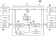
图2是表示图1的机器人系统的控制系统的结构的框图。FIG. 2 is a block diagram showing the configuration of a control system of the robot system in FIG. 1 .

图3是例示反作用力以及由夸大表现部生成的修正成分的时间变化的图表。FIG. 3 is a graph illustrating temporal changes of reaction forces and correction components generated by an exaggerated expression unit.

图4是表示本发明的第2实施方式所涉及的机器人系统的控制系统的结构的框图。4 is a block diagram showing the configuration of a control system of a robot system according to a second embodiment of the present invention.

图5是表示本发明的第3实施方式所涉及的机器人系统的控制系统的结构的框图。5 is a block diagram showing the configuration of a control system of a robot system according to a third embodiment of the present invention.

图6是表示机器人系统的动作的一个例子的示意图。FIG. 6 is a schematic diagram showing an example of the operation of the robot system.

具体实施方式detailed description

以下,参照附图并且对优选的实施方式进行说明。此外,以下在全部的附图中对相同或相当的要素标注相同的参照附图标记,省略其重复的说明。另外,为了便于理解附图,示意性地示出了各个构成要素。Hereinafter, preferred embodiments will be described with reference to the drawings. In addition, in the following, the same or corresponding elements are given the same reference numerals in all the drawings, and the overlapping description thereof will be omitted. In addition, in order to facilitate understanding of the drawings, each component is schematically shown.

(第1实施方式)(first embodiment)

图1是表示本发明的第1实施方式所涉及的机器人系统的结构例的示意图。如图1所示,本实施方式的机器人系统100构成为从动臂1由主控臂2远程操作。机器人系统100是主从式的远程操作系统。FIG. 1 is a schematic diagram illustrating a configuration example of a robot system according to a first embodiment of the present invention. As shown in FIG. 1 , therobot system 100 of this embodiment is configured such that theslave arm 1 is remotely operated by themaster arm 2 . Therobot system 100 is a master-slave remote operation system.

机器人系统100具备由第1机器人构成的从动臂1、由第2机器人构成的主控臂2、控制装置3、力觉传感器4、照相机5以及监视器6。从动臂1能够由任意类型的机器人构成。在本实施方式中,例如,从动臂1由公知的多关节机器人构成,具备基台1a、设置于基台1a的多关节手臂1b以及设置于手臂1b的末端的手腕1c。将以基台1a的上表面为基准的坐标系称为从动臂1的基座坐标系。多关节的手臂1b的各关节具备驱动用的伺服马达、检测伺服马达的旋转角度位置的编码器、以及检测流向伺服马达的电流的电流传感器(均未图示)。在手腕1c安装有末端执行器7。末端执行器7相当于本发明的“作业端”。末端执行器7是能够把持工件的机械手。末端执行器7具备安装于手腕1c末端的手主体(未图示)和例如被由马达构成的致动器(未图示)驱动的两根指部。若致动器动作则两根指部相对于手主体移动。手的两根指部能够通过主控臂2的操作,以相互接近或隔离的方式移动,能够利用两根指部把持嵌合部件W1。Therobot system 100 includes aslave arm 1 composed of a first robot, amaster arm 2 composed of a second robot, acontrol device 3 , aforce sensor 4 , acamera 5 , and a monitor 6 . Theslave arm 1 can be constituted by any type of robot. In this embodiment, for example, theslave arm 1 is composed of a known articulated robot, and includes abase 1a, a articulatedarm 1b provided on thebase 1a, and awrist 1c provided at the end of thearm 1b. The coordinate system based on the upper surface of thebase 1 a is referred to as a base coordinate system of theslave arm 1 . Each joint of themulti-joint arm 1b includes a servomotor for driving, an encoder for detecting the rotational angle position of the servomotor, and a current sensor (both not shown) for detecting a current flowing to the servomotor. Anend effector 7 is attached to thewrist 1c. Theend effector 7 corresponds to the "working end" of the present invention. Theend effector 7 is a robot arm capable of holding a workpiece. Theend effector 7 includes a hand body (not shown) attached to the end of thewrist 1c, and two fingers driven by an actuator (not shown) composed of a motor, for example. When the actuator operates, the two fingers move relative to the main body of the hand. The two fingers of the hand can be moved so as to approach or separate from each other by the operation of themaster arm 2 , and the fitting member W1 can be grasped by the two fingers.

力觉传感器4安装于从动臂1的手腕1c。力觉传感器4检测施加于由末端执行器7保持的工件的反作用力。力觉传感器4相当于本发明的“反作用力检测部”。在本实施方式中,力觉传感器4构成为安装于末端执行器7的基端,探测施加于末端执行器7的末端的力。力觉传感器4是能够检测例如由手腕坐标系定义的XYZ轴方向的力和围绕各轴作用的力矩的六轴力觉传感器。这里手腕坐标系是指以手腕1c为基准的坐标系。在本实施方式中,力觉传感器4构成为,在作为由末端执行器7保持的工件的嵌合部件W1接触到作为对象物的被嵌合部件W2时,检测从动臂1的基座坐标系中的作用于嵌合部件W1的反作用力的方向和其大小,并将检测信号通过无线或有线向控制装置3发送。Theforce sensor 4 is attached to thewrist 1c of theslave arm 1 . Theforce sensor 4 detects the reaction force applied to the workpiece held by theend effector 7 . Theforce sensor 4 corresponds to the "reaction force detection unit" of the present invention. In the present embodiment, theforce sensor 4 is attached to the proximal end of theend effector 7 to detect the force applied to the end of theend effector 7 . Theforce sensor 4 is a six-axis force sensor capable of detecting, for example, forces in the XYZ axis directions defined by the wrist coordinate system and moments acting around the respective axes. Here, the wrist coordinate system refers to a coordinate system based on thewrist 1c. In the present embodiment, theforce sensor 4 is configured to detect the base coordinates of theslave arm 1 when the fitting member W1, which is a workpiece held by theend effector 7, comes into contact with the fitted member W2, which is an object. The direction and magnitude of the reaction force acting on the fitting part W1 in the system, and the detection signal is sent to thecontrol device 3 by wireless or wired.

主控臂2能够由任意类型的机器人构成。在本实施方式中,主控臂2具有与从动臂1相似的构造。即,主控臂2也与从动臂1同样由多关节机器人构成,以主控臂2的基台的上表面作为基准定义主控臂2的基座坐标系。多关节的手臂的各关节具备驱动用的伺服马达、检测伺服马达的旋转角度位置的编码器、以及检测流向伺服马达的电流的电流传感器(均未图示)。在主控臂2的末端安装有模仿了从动臂1末端的末端执行器7的形状的操作手柄21。操作手柄21相当于本发明的“操作端”。此外,“操作端”只要是能够通过由操作人员进行操作来操作从动臂1的结构即可,例如可以是开关、调整旋钮或平板等移动终端,也可以是像操纵杆那样的简易的结构。在操作手柄21安装有力觉传感器20。力觉传感器20检测由操作人员施加于操作手柄21的操作力。力觉传感器20相当于本发明的“操作力检测部”。在本实施方式中,力觉传感器20构成为安装于操作手柄21的基端,探测施加于操作手柄21的末端的力。例如,力觉传感器20是能够检测由主控臂2的手腕坐标系定义的XYZ轴方向的力和围绕各轴作用的力矩的六轴力觉传感器。这里,手腕坐标系是指以主控臂2的手腕为基准的坐标系。在本实施方式中,若操作人员为了操作从动臂1而操作操作手柄21,则力觉传感器20在主控臂2的基座坐标系中,检测操作人员施加于操作手柄21的操作力的方向和大小,将检测信号作为操作信息,通过无线或有线向控制装置3发送。Themaster control arm 2 can be constituted by any type of robot. In the present embodiment, themaster arm 2 has a configuration similar to that of theslave arm 1 . That is, themaster arm 2 is also composed of an articulated robot like theslave arm 1 , and the base coordinate system of themaster arm 2 is defined with the upper surface of the base of themaster arm 2 as a reference. Each joint of the multi-joint arm includes a servo motor for driving, an encoder for detecting the rotational angle position of the servo motor, and a current sensor (both not shown) for detecting the current flowing to the servo motor. An operating handle 21 imitating the shape of theend effector 7 at the end of theslave arm 1 is installed at the end of themaster control arm 2 . The operatinghandle 21 corresponds to the "operating end" of the present invention. In addition, as long as the "operating end" is a structure that can be operated by an operator to operate theslave arm 1, for example, it may be a switch, an adjustment knob, or a mobile terminal such as a tablet, or it may be a simple structure such as a joystick. . Aforce sensor 20 is attached to theoperating handle 21 . Theforce sensor 20 detects the operating force applied to the operating handle 21 by the operator. Theforce sensor 20 corresponds to the "operation force detection unit" of the present invention. In the present embodiment, theforce sensor 20 is attached to the proximal end of the operating handle 21 to detect the force applied to the distal end of theoperating handle 21 . For example, theforce sensor 20 is a six-axis force sensor capable of detecting force in the XYZ axis directions defined by the wrist coordinate system of themaster arm 2 and moments acting around each axis. Here, the wrist coordinate system refers to a coordinate system based on the wrist of themaster arm 2 . In this embodiment, if the operator operates the operatinghandle 21 in order to operate theslave arm 1, theforce sensor 20 detects the percentage of the operating force applied to the operating handle 21 by the operator in the base coordinate system of themaster arm 2. The direction and magnitude are sent to thecontrol device 3 wirelessly or by wire using the detection signal as operation information.

照相机5被设置成能够拍摄从动臂1的可动范围的全部或一部分中的该从动臂1的动作。照相机5拍摄的图像信息被发送至控制装置3,控制装置3控制监视器6以便显示与该图像信息对应的图像。Thecamera 5 is installed so as to be able to photograph the movement of theslave arm 1 in the whole or a part of the movable range of theslave arm 1 . The image information captured by thecamera 5 is sent to thecontrol device 3, and thecontrol device 3 controls the monitor 6 so as to display an image corresponding to the image information.

在机器人系统100中,位于远离从动臂1的作业领域的位置(作业区域外)的操作人员一边观察在监视器6放映的照相机5的影像一边对主控臂2的操作手柄21施加所希望的操作力作为操作信息的输入。根据操作力,从动臂1跟随主控臂2进行动作,从而能够进行特定的作业。特定作业例如是将作为由末端执行器7保持的工件的嵌合部件W1插入至作为对象物的被嵌合部件W2的孔的作业。该作业在组装作业中也需要操作人员的熟练。In therobot system 100, an operator located at a position away from the work area of the slave arm 1 (outside the work area) applies a desired action to the operation handle 21 of themaster arm 2 while observing the image of thecamera 5 projected on the monitor 6. The operating force is used as the input of operation information. According to the operation force, theslave arm 1 moves following themaster arm 2, so that specific work can be performed. The specific work is, for example, a work of inserting the fitting member W1 which is the workpiece held by theend effector 7 into the hole of the mated member W2 which is the object. This work also requires the skill of the operator in the assembly work.

另外,在机器人系统100中,从动臂1也能够不需要操作人员对于主控臂2的操作,而自动地进行指定的作业。在本说明书中,将根据经由主控臂2输入的操作信息而使从动臂1动作的运转模式称为“手动模式”。此外,在上述的“手动模式”中,也包括基于通过操作人员操作主控臂2而输入的操作信息,自动地对动作中的从动臂1的动作的一部分进行动作补正的情况。另外,将根据预先设定的指定程序而使从动臂1动作的运转模式称为“自动模式”。并且,在本实施方式的机器人系统100中,构成为能够在从动臂1自动动作的中途,将主控臂2的操作反映到从动臂1的自动的动作中,从而修正自动进行的动作。在本说明书中,在能够反映经由主控臂2而输入的操作信息的状态下,将根据预先设定的指定程序而使从动臂1动作的运转模式称为“修正自动模式”。此外,上述的“自动模式”与“修正自动模式”的区别在于,在使从动臂1动作的运转模式为自动模式时,主控臂2的操作不反映于从动臂1的动作。以下,只要没有特殊说明,本实施方式的机器人系统100作为“手动模式”进行动作。In addition, in therobot system 100 , theslave arm 1 can also automatically perform a designated work without requiring an operator to operate themaster arm 2 . In this specification, the operation mode in which theslave arm 1 is operated based on the operation information input via themaster arm 2 is referred to as "manual mode". In addition, the above-mentioned "manual mode" also includes a case where a part of the motion of theslave arm 1 in motion is automatically corrected based on the operation information input by the operator operating themaster arm 2 . In addition, the operation mode which operates theslave arm 1 according to the preset designation program is called "automatic mode". In addition, in therobot system 100 of the present embodiment, the operation of themaster arm 2 is reflected in the automatic movement of theslave arm 1 during the automatic movement of theslave arm 1, thereby correcting the automatically performed movement. . In this specification, the operation mode in which theslave arm 1 is operated according to a preset designation program in a state where operation information input via themaster arm 2 can be reflected is referred to as a "correction automatic mode". The difference between the above-mentioned "automatic mode" and "correction automatic mode" is that when the operation mode for actuating theslave arm 1 is the automatic mode, the operation of themaster arm 2 is not reflected in the operation of theslave arm 1 . Hereinafter, unless otherwise specified, therobot system 100 of this embodiment operates as a "manual mode".

图2是表示机器人系统100的控制系统的结构的框图。如图2所示,控制装置3包括动作指令生成部8、夸大表现部9以及接口部(未图示)。在本实施方式中,控制装置3与输入装置(未图示)连接。输入装置由触摸面板、键盘等人机界面构成,主要在从动臂1的“自动模式”、“修正自动模式”以及“手动模式”的模式切换、输入各种数据等中使用。控制装置3由计算机、微型控制器、微型处理器等具有运算处理功能和存储器的装置构成。通过由控制装置3的运算处理部(未图示)执行储存于控制装置3的存储器的指定程序来实现动作指令生成部8和夸大表现部9的各功能。另外,本实施方式的控制装置3也具有显示与由照相机5拍摄的图像信息对应的图像的监视控制部的功能。控制装置3的硬件上的结构不受限定,控制装置3可以与从动臂1等其他的装置独立设置,也可以与其他的装置一体地设置。本实施方式的机器人系统100是基于并列型双向控制方式的主从型的机器人系统。由主控臂2的力觉传感器20检测到的操作力fm和由从动臂1的力觉传感器4检测到的反作用力fs被输入至控制装置3。FIG. 2 is a block diagram showing the configuration of a control system of therobot system 100 . As shown in FIG. 2 , thecontrol device 3 includes an operation command generation unit 8 , anexaggerated expression unit 9 , and an interface unit (not shown). In this embodiment, thecontrol device 3 is connected to an input device (not shown). The input device consists of a human-machine interface such as a touch panel and a keyboard, and is mainly used for switching between "automatic mode", "correction automatic mode" and "manual mode" of theslave arm 1, and inputting various data. Thecontrol device 3 is constituted by a computer, a microcontroller, a microprocessor, and other devices having arithmetic processing functions and memories. The respective functions of the operation command generation unit 8 and theexaggerated expression unit 9 are realized by an arithmetic processing unit (not shown) of thecontrol device 3 executing a predetermined program stored in a memory of thecontrol device 3 . In addition, thecontrol device 3 of the present embodiment also has a function of a monitor control unit that displays an image corresponding to image information captured by thecamera 5 . The hardware structure of thecontrol device 3 is not limited, and thecontrol device 3 may be provided independently from other devices such as theslave arm 1 or may be provided integrally with other devices. Therobot system 100 of the present embodiment is a master-slave robot system based on a parallel bidirectional control method. The operating force fm detected by theforce sensor 20 of themaster arm 2 and the reaction force fs detected by theforce sensor 4 of theslave arm 1 are input to thecontrol device 3 .

动作指令生成部8基于由主控臂2的力觉传感器20检测到的操作力fm和由从动臂1的力觉传感器4检测到的反作用力fs,生成从动臂1的动作指令(以下,也称为从动动作指令),并且生成主控臂2的动作指令(以下,也称为主控动作指令)。在本实施方式中,从动动作指令是由从动臂1的基座坐标系规定的、驱动从动臂1的各关节轴的伺服马达的位置指令。主控动作指令是由主控臂2的基座坐标系规定的、驱动主控臂2的各关节轴的伺服马达的位置指令。主控动作指令生成以使操作手柄21向与基于从动动作指令的末端执行器7的移动方向相同的方向移动。即,从动臂1和主控臂2进行相同的动作。The motion command generator 8 generates motion commands for theslave arm 1 based on the operating force fm detected by theforce sensor 20 of themaster arm 2 and the reaction force fs detected by theforce sensor 4 of the slave arm 1 (hereinafter also referred to as a slave operation command), and an operation command of the master arm 2 (hereinafter also referred to as a master operation command) is generated. In the present embodiment, the slave operation command is a position command of a servo motor that drives each joint axis of theslave arm 1 , which is defined by the base coordinate system of theslave arm 1 . The master control action command is a position command of a servo motor that drives each joint axis of themaster arm 2 , which is specified by the base coordinate system of themaster arm 2 . The master motion command is generated to move theoperating handle 21 in the same direction as the movement direction of theend effector 7 based on the slave motion command. That is, theslave arm 1 and themaster arm 2 perform the same operation.

具体而言,动作指令生成部8具备加减部81、力/速度变换部82、速度/位置变换部83(从动侧)、速度/位置变换部84(主控侧)、以及加减部85。通过由控制装置3的运算处理部(未图示)执行储存于控制装置3的存储器(未图示)的指定程序从而实现各部81~85。Specifically, the operation command generation unit 8 includes an addition andsubtraction unit 81, a force/speed conversion unit 82, a speed/position conversion unit 83 (slave side), a speed/position conversion unit 84 (master side), and an addition and subtraction unit. 85. Each of theunits 81 to 85 is realized by an arithmetic processing unit (not shown) of thecontrol device 3 executing a predetermined program stored in a memory (not shown) of thecontrol device 3 .

加减部81构成为从由主控臂2的力觉传感器20探测的操作力fm减去由从动臂1的力觉传感器4探测的反作用力fs,并将所得值向力/速度变换部82输出。The addition andsubtraction unit 81 is configured to subtract the reaction force fs detected by theforce sensor 4 of theslave arm 1 from the operation force fm detected by theforce sensor 20 of themaster arm 2, and convert the obtained value to the force/speed Theconversion unit 82 outputs.

力/速度变换部82基于从加减部81输入的操作力fm与反作用力fs的差量,生成速度指令值vd,并将其向速度/位置变换部83(从动侧)、以及加减部85分别输出。The force/speed conversion unit 82 generates a speed command value vd based on the difference between the operation force fm input from the addition andsubtraction unit 81 and the reaction force fs , and sends it to the speed/position conversion unit 83 (driven side), and the addition andsubtraction unit 85 respectively output.

速度/位置变换部83(从动侧)基于vd速度指令值vd生成从动臂1的位置指令值xds,并将其向从动侧控制部30输出。从动侧控制部30例如是构成为对从动臂1进行位置控制的机器人控制器。从动侧控制部30基于从动臂1的各关节轴的位置指令值与编码器(未图示)的检测值(实际值)的偏差生成速度指令值。而且,基于生成的速度指令值与速度当前值的偏差生成扭矩指令值(电流指令值),基于生成的电流指令值与电流传感器的检测值(实际值)的偏差控制伺服马达。The speed/position conversion unit 83 (slave side) generates a position command value xds of theslave arm 1 based on the vd speed command value vd and outputs it to the slaveside control unit 30 . The slave-side control unit 30 is, for example, a robot controller configured to control the position of theslave arm 1 . The slave-side control unit 30 generates a speed command value based on a deviation between a position command value of each joint axis of theslave arm 1 and a detection value (actual value) of an encoder (not shown). Then, the torque command value (current command value) is generated based on the deviation between the generated speed command value and the current speed value, and the servo motor is controlled based on the deviation between the generated current command value and the detection value (actual value) of the current sensor.

速度/位置变换部84(主控侧)基于速度指令值vd生成主控臂2的位置指令值xdm,并将其向主控侧控制部12输出。主控侧控制部12例如是构成为对主控臂2进行位置控制的机器人控制器。主控侧控制部12基于主控臂2的各关节轴的位置指令值与编码器(未图示)的检测值(实际值)的偏差生成速度指令值。而且,基于生成的速度指令值与速度当前值的偏差生成扭矩指令值(电流指令值),基于生成的电流指令值与电流传感器的检测值(实际值)的偏差控制伺服马达。The speed/position conversion unit 84 (master side) generates a position command value xdm of themaster arm 2 based on the speed command value vd and outputs it to the masterside control unit 12 . The master-side control unit 12 is, for example, a robot controller configured to control the position of themaster arm 2 . The master-side control unit 12 generates a speed command value based on a deviation between a position command value of each joint axis of themaster arm 2 and a detection value (actual value) of an encoder (not shown). Then, the torque command value (current command value) is generated based on the deviation between the generated speed command value and the current speed value, and the servo motor is controlled based on the deviation between the generated current command value and the detection value (actual value) of the current sensor.

夸大表现部9构成为,在由从动臂1的力觉传感器4检测的反作用力fs急剧地随时间变化了的反作用力骤变状态下,对操作操作手柄21的操作人员夸大地提示操作感觉。具体而言,在反作用力骤变状态下,夸大表现部9基于反作用力fs生成用于修正主控臂2的位置指令值xdm的修正成分,并将其向加减部85输出。Theexaggerated expression unit 9 is configured to exaggerately prompt the operator who operates the operatinghandle 21 to operate in a state where the reaction force fs detected by theforce sensor 4 of theslave arm 1 changes rapidly with time. Feel. Specifically, in the reaction force sudden change state, theexaggeration expression unit 9 generates a correction component for correcting the position command value xdm of themaster arm 2 based on the reaction force fs , and outputs it to the addition andsubtraction unit 85 .

加减部85将由力/速度变换部82生成的速度指令值vd与由夸大表现部9生成的修正成分相加,并将其向速度/位置变换部84输出。速度/位置变换部84(主控侧)基于被修正的速度指令值vd更新主控臂2的位置指令值xdm,并将其向主控侧控制部12输出。这样,从动臂1的反作用力fs反映于主控臂2的位置指令值xdmThe addition andsubtraction unit 85 adds the speed command value vd generated by the force/speed conversion unit 82 and the correction component generated by theexaggeration expression unit 9 , and outputs it to the speed/position conversion unit 84 . The speed/position conversion unit 84 (master side) updates the position command value xdm of themaster arm 2 based on the corrected speed command value vd and outputs it to the masterside control unit 12 . In this way, the reaction force fs of theslave arm 1 is reflected on the position command value xdm of themaster arm 2 .

接下来,参照附图并且对机器人系统的动作进行说明。如图1所示,在机器人系统100中,操作人员一边观察在监视器6放映的照相机5的影像一边对主控臂2的操作手柄21施加所希望的操作力作为操作信息的输入。根据操作力,从动臂1跟随主控臂2进行动作。即,操作人员通过一边观察监视器6一边操作操作手柄21,从而按照操作人员想要的方式操作主控臂2和从动臂1。而且,设想作为由从动臂1的末端执行器7保持的工件的嵌合部件W1与作为被嵌合部件W2的对象物接触的情况。图3(a)是示意性地表示由从动臂1的力觉传感器4检测的反作用力fs的时间变化的图表。在时刻t0处,由从动臂1的力觉传感器4检测的反作用力fs急剧地上升。夸大表现部9在由从动臂1的力觉传感器4检测的反作用力fs急剧地随时间变化了的反作用力骤变状态下,对操作操作手柄21的操作人员夸大地提示操作感觉(参照图2)。对于夸大表现部9来说,例如可以在反作用力fs为预先存储于存储器的指定值以上的情况下判定为反作用力骤变初始状态,也可以以反作用力fs的微小时间Δt内的变化量是否为正判定反作用力骤变状态。在反作用力骤变状态中,夸大表现部9基于反作用力fs生成用于修正主控臂2的位置指令值xdm的修正成分,并将其向加减部85输出。加减部85将由力/速度变换部82生成的速度指令值vd与由夸大表现部9生成的修正成分相加,并将其向速度/位置变换部84输出。速度/位置变换部84(主控侧)基于被修正的速度指令值vd更新主控臂2的位置指令值xdm,并将其向主控侧控制部12输出。这样,从动臂1的反作用力fs反映于主控臂2的位置指令值xdm,因此操作人员能够识别从动臂1的末端执行器7与对象物接触的情况。由此,在并列型双向控制中,能够提示高频的细小感觉。Next, the operation of the robot system will be described with reference to the drawings. As shown in FIG. 1 , in therobot system 100 , the operator applies a desired operation force to the operation handle 21 of themaster arm 2 as input of operation information while observing the image of thecamera 5 projected on the monitor 6 . According to the operating force, theslave arm 1 follows themaster arm 2 to move. That is, the operator manipulates the operating handle 21 while looking at the monitor 6 to operate themaster arm 2 and theslave arm 1 as the operator desires. Furthermore, assume a case where the fitting member W1 which is a workpiece held by theend effector 7 of theslave arm 1 comes into contact with an object which is a member to be fitted W2. FIG. 3( a ) is a graph schematically showing temporal changes in the reaction force fs detected by theforce sensor 4 of theslave arm 1 . At time t0, the reaction force fs detected by theforce sensor 4 of theslave arm 1 rises sharply. Theexaggerated expression part 9 presents an operation feeling to the operator who operates the operation handle 21 in an exaggerated manner in a state in which the reaction forcefs detected by theforce sensor 4 of theslave arm 1 changes rapidly with time. figure 2). For theexaggerated expression part 9, for example, when the reaction force fs is greater than or equal to a predetermined value stored in the memory in advance, it may be determined as the initial state of a sudden change in the reaction force, or it may be determined as a change in the reaction force fs within a minute time Δt Whether the quantity is positive or not determines the sudden change state of the reaction force. In the reaction force sudden change state, theexaggerated expression unit 9 generates a correction component for correcting the position command value xdm of themaster arm 2 based on the reaction force fs , and outputs it to the addition andsubtraction unit 85 . The addition andsubtraction unit 85 adds the speed command value vd generated by the force/speed conversion unit 82 and the correction component generated by theexaggeration expression unit 9 , and outputs it to the speed/position conversion unit 84 . The speed/position conversion unit 84 (master side) updates the position command value xdm of themaster arm 2 based on the corrected speed command value vd and outputs it to the masterside control unit 12 . In this way, the reaction force fs of theslave arm 1 is reflected on the position command value xdm of themaster arm 2 , so the operator can recognize that theend effector 7 of theslave arm 1 is in contact with the object. Thus, in the parallel-type two-way control, it is possible to present a subtle feeling of high frequencies.

在本实施方式中,夸大表现部9能够根据作业对象物的性质生成各种修正成分。图3(b)~图3(d)是例示修正成分的时间变化的图表。图3(b)表示修正成分是三角波成分的情况。如图3(b)所示,在反作用力骤变状态下,夸大表现部9生成1个周期的三角波成分作为修正成分。此外,相当于三角波成分的1个周期的期间例如为40msec,但只要是操作人员能够察觉的程度的长度即可。加减部85将由力/速度变换部82生成的速度指令值vd与由夸大表现部9生成的修正成分相加,并将其向速度/位置变换部84输出。速度/位置变换部84(主控侧)基于被修正的速度指令值vd更新主控臂2的位置指令值xdm,并将其向主控侧控制部12输出。通过使用三角波成分作为修正成分,从而能够对操作主控臂2的操作人员夸大表现从动臂1碰到坚硬的对象物的感觉。In the present embodiment, theexaggerated expression unit 9 can generate various correction components according to the properties of the work object. 3(b) to 3(d) are graphs illustrating temporal changes of correction components. Fig. 3(b) shows the case where the correction component is a triangular wave component. As shown in FIG. 3( b ), in the reaction force sudden change state, theexaggerated expression unit 9 generates a triangular wave component of one period as a correction component. In addition, the period corresponding to one cycle of the triangular wave component is, for example, 40 msec, but it may be as long as the operator can perceive it. The addition andsubtraction unit 85 adds the speed command value vd generated by the force/speed conversion unit 82 and the correction component generated by theexaggeration expression unit 9 , and outputs it to the speed/position conversion unit 84 . The speed/position conversion unit 84 (master side) updates the position command value xdm of themaster arm 2 based on the corrected speed command value vd and outputs it to the masterside control unit 12 . By using the triangular wave component as the correction component, it is possible to exaggerate the feeling of theslave arm 1 touching a hard object to the operator who operates themaster arm 2 .

图3(c)表示修正成分是正弦波成分的情况。如图3(c)所示,在反作用力骤变状态下,夸大表现部9生成1个周期的正弦波成分作为修正成分。加减部85将由力/速度变换部82生成的速度指令值vd与由夸大表现部9生成的修正成分相加,并将其向速度/位置变换部84输出。速度/位置变换部84(主控侧)基于被修正的速度指令值vd更新主控臂2的位置指令值xdm,并将其向主控侧控制部12输出。通过使用正弦波成分作为修正成分,从而能够对操作主控臂2的操作人员夸大表现从动臂1碰到柔软的对象物的感觉。Fig. 3(c) shows a case where the correction component is a sine wave component. As shown in FIG. 3( c ), in the reaction force sudden change state, theexaggerated expression unit 9 generates a sine wave component of one cycle as a correction component. The addition andsubtraction unit 85 adds the speed command value vd generated by the force/speed conversion unit 82 and the correction component generated by theexaggeration expression unit 9 , and outputs it to the speed/position conversion unit 84 . The speed/position conversion unit 84 (master side) updates the position command value xdm of themaster arm 2 based on the corrected speed command value vd and outputs it to the masterside control unit 12 . By using the sine wave component as the correction component, it is possible to exaggerate the feeling of theslave arm 1 touching a soft object to the operator who operates themaster arm 2 .

图3(d)表示修正成分是反作用力fs的时间t的二阶微分值的情况。如图3(d)所示,在反作用力骤变状态下,夸大表现部9生成相当于三角波成分、正弦波成分的1个周期的成分作为修正成分。加减部85将由力/速度变换部82生成的速度指令值vd与由夸大表现部9生成的修正成分相加,并将其向速度/位置变换部84输出。速度/位置变换部84(主控侧)基于被修正的速度指令值vd更新主控臂2的位置指令值xdm,并将其向主控侧控制部12输出。通过使用反作用力fs的时间t的二阶微分值作为修正成分,从而能够对操作主控臂2的操作人员夸大表现从动臂1实际碰到对象物的感觉。FIG. 3( d ) shows the case where the correction component is the second order differential value of the reaction force fs at time t. As shown in FIG. 3( d ), in the reaction force sudden change state, theexaggerated expression unit 9 generates a component corresponding to one cycle of the triangular wave component and the sine wave component as a correction component. The addition andsubtraction unit 85 adds the speed command value vd generated by the force/speed conversion unit 82 and the correction component generated by theexaggeration expression unit 9 , and outputs it to the speed/position conversion unit 84 . The speed/position conversion unit 84 (master side) updates the position command value xdm of themaster arm 2 based on the corrected speed command value vd and outputs it to the masterside control unit 12 . By using the second-order differential value of the reaction force fs at time t as a correction component, it is possible to exaggerate the feeling that theslave arm 1 actually touches the object to the operator who operates themaster arm 2 .

(第2实施方式)(second embodiment)

接下来,对第2实施方式进行说明。本实施方式的机器人系统的基本结构与第1实施方式相同。以下,省略与第1实施方式共同的结构的说明,仅对不同的结构进行说明。Next, a second embodiment will be described. The basic configuration of the robot system of this embodiment is the same as that of the first embodiment. Hereinafter, the description of the configurations common to the first embodiment will be omitted, and only the different configurations will be described.

图4是表示本发明的第2实施方式所涉及的机器人系统的控制系统的结构的框图。如图4所示,在本实施方式的机器人系统100A中,若与第1实施方式进行比较,则不同的点在于控制装置3A还具备位置偏移补正部92和加减部91。4 is a block diagram showing the configuration of a control system of a robot system according to a second embodiment of the present invention. As shown in FIG. 4 , the difference between therobot system 100A of this embodiment and the first embodiment is that thecontrol device 3A further includes a positionaldeviation correction unit 92 and an addition andsubtraction unit 91 .

位置偏移补正部92基于从动臂1的位置信息和加入了修正成分的主控臂2的位置信息,生成用于补正从动臂1与主控臂2的位置关系的偏移的补正成分。具体而言,位置偏移补正部92计算从动臂的位置指令值xds与加入了修正成分的主控臂的位置指令值xdm的偏差的累计值,生成用于补正主控臂2的位置指令值xdm的补正成分。The positionaldeviation correcting unit 92 generates a correction component for correcting a deviation in the positional relationship between theslave arm 1 and themaster arm 2 based on the position information of theslave arm 1 and the position information of themaster arm 2 to which the correction component has been added. . Specifically, the positiondeviation correcting unit 92 calculates the cumulative value of the deviation between the position command valuexds of the slave arm and the position command value xdm of the master arm to which the correction component is added, and generates a value for correcting the position command valuexds of themaster arm 2. Correction component of the position command value xdm .

加减部91将由位置偏移补正部92生成的补正成分与由夸大表现部9生成的修正成分相加,并将其向加减部85输出。加减部85将由力/速度变换部82生成的速度指令值vd与向由夸大表现部9生成的修正成分加入了位置偏移的补正成分的成分相加,并将其向速度/位置变换部84输出。速度/位置变换部84(主控侧)基于被修正和补正的速度指令值vd更新主控臂2的位置指令值xdm,并将其向主控侧控制部12输出。由此,在并列型双向控制中,能够逐渐地补正由夸大表现部9产生的主控臂2与从动臂1的位置关系的偏移。为了不给操作人员带来不协调感,在夸大表现了操作感觉后,主控臂2缓慢地移动并被补正,因此不会对主控臂2的操作造成影响。The addition andsubtraction unit 91 adds the correction component generated by the positionaldisplacement correction unit 92 and the correction component generated by theexaggerated expression unit 9 , and outputs this to the addition andsubtraction unit 85 . The addition andsubtraction unit 85 adds the speed command value vd generated by the force/speed conversion unit 82 to the correction component generated by theexaggeration expression unit 9 by adding the correction component of the position offset, and converts it to the speed/position Section 84 outputs. The speed/position conversion unit 84 (master side) updates the position command value xdm of themaster arm 2 based on the corrected and corrected speed command value vd and outputs it to the masterside control unit 12 . Thus, in the parallel bidirectional control, it is possible to gradually correct the deviation in the positional relationship between themaster arm 2 and theslave arm 1 caused by theexaggerated expression unit 9 . In order not to give the operator a sense of incongruity, themaster arm 2 is moved slowly and corrected after exaggerating the operating feeling, so that the operation of themaster arm 2 is not affected.

此外,在本实施方式中,位置偏移补正部92构成为,基于从动臂1的位置指令值xds和加入了修正成分的主控臂2的位置指令值xdm,计算这些偏差的累计值,但只要是从动臂1和主控臂2的位置信息,也可以使用对设置于各关节的伺服马达的旋转角度位置进行检测的编码器的检测值(实际值)。In addition, in the present embodiment, the positiondeviation correcting unit 92 is configured to calculate the cumulative value of these deviations based on the position command value xds of theslave arm 1 and the position command value xdm of themaster arm 2 to which correction components have been added. However, as long as it is the position information of theslave arm 1 and themaster arm 2, the detection value (actual value) of the encoder which detects the rotational angle position of the servo motor provided in each joint may be used.

(第3实施方式)(third embodiment)

接下来,对第3实施方式进行说明。本实施方式的机器人系统的基本结构与上述实施方式相同。以下,省略与上述实施方式共同的结构的说明,仅对不同的结构进行说明。Next, a third embodiment will be described. The basic structure of the robot system of this embodiment is the same as that of the above-mentioned embodiment. Hereinafter, the description of the configuration common to the above-mentioned embodiment will be omitted, and only the different configuration will be described.

图5是表示本发明的第3实施方式所涉及的机器人系统的控制系统的结构的框图。如图5所示,若将本实施方式的机器人系统100B与第2实施方式(图4)进行比较,则不同的点在于控制装置3B的夸大表现部9还具备作业状态判定部93和作业状态提示部13。5 is a block diagram showing the configuration of a control system of a robot system according to a third embodiment of the present invention. As shown in FIG. 5 , when comparing therobot system 100B of this embodiment with the second embodiment ( FIG. 4 ), the difference lies in that theexaggerated expression unit 9 of thecontrol device 3B further includes a workstate determination unit 93 and a workstate determination unit 93 .Prompt section 13.

在本实施方式中,在存储器94中,预先收集特定作业中的从动臂1的位置指令值xds、主控臂2的操作力fm、以及从动臂1的反作用力fs作为数据,根据收集到的数据对至少一个以上的作业状态进行分类,并存储分类后的作业状态。特定作业是将作为由末端执行器7保持的工件的嵌合部件W1插入至作为对象物的被嵌合部件W2的孔的作业。例示有开始作业的状态、正在寻找对象物的状态、以及工件插入至对象物的状态作为作业状态。In the present embodiment, the position command value xds of theslave arm 1 , the operation force fm of themaster arm 2 , and the reaction force fs of theslave arm 1 during a specific operation are collected in advance as data in thememory 94 , classify at least one job status according to the collected data, and store the classified job status. The specific work is a work of inserting the fitting member W1 which is the workpiece held by theend effector 7 into the hole of the mated member W2 which is the object. Examples of the work state include a state in which work is started, a state in which an object is being searched, and a state in which a workpiece is inserted into an object.

在机器人系统100B的动作中,作业状态判定部93基于从动臂1的位置指令值xds、主控臂2的操作力fm、以及从动臂1的反作用力fs中至少一个值,判定是否分类为存储于存储器94的作业状态的其中一个。在本实施方式中,作业状态判定部93判定是否为开始作业的状态、正在寻找对象物的状态、以及工件插入至对象物的状态中的任一个作业状态。作业状态提示部13构成为通过声音、主控臂的振动以及光中的至少一个将作业状态提示给操作人员。During the operation of therobot system 100B, the workstate determination unit 93 based on at least one of the position command value xds of theslave arm 1 , the operation force fm of themaster arm 2 , and the reaction force fs of theslave arm 1 , It is determined whether it is classified as one of the job states stored in thememory 94 . In the present embodiment, the workstate judging unit 93 judges whether or not the work state is any one of the state where the work is started, the state where the object is being searched, and the state where the workpiece is inserted into the object. The workingstate presentation unit 13 is configured to present the working state to the operator by at least one of sound, vibration of the master arm, and light.

接下来,使用附图对本实施方式的机器人系统100B的动作进行说明。如图6所示,对于从动臂1的手腕坐标系来说,与手腕1c的安装面平行地定义X轴和Y轴,在与安装面垂直的方向定义Z轴。对于主控臂2的手腕坐标系来说,与手腕2c的安装面平行地定义X轴和Y轴,在与安装面垂直的方向定义Z轴。如图6(a)所示,在机器人系统100B中,操作人员一边观察在监视器6中放映的照相机5的影像一边对主控臂2的操作手柄21施加所希望的操作力作为操作信息的输入。根据操作力,从动臂1跟随主控臂2进行动作。操作人员一边观察监视器6一边操作操作手柄21,以便将作为由末端执行器7保持的工件的嵌合部件W1插入至作为对象物的被嵌合部件W2的孔H。Next, the operation of therobot system 100B of this embodiment will be described using the drawings. As shown in FIG. 6 , in the wrist coordinate system of theslave arm 1 , an X-axis and a Y-axis are defined parallel to the mounting surface of thewrist 1c, and a Z-axis is defined in a direction perpendicular to the mounting surface. In the wrist coordinate system of themaster arm 2, an X axis and a Y axis are defined parallel to the mounting surface of thewrist 2c, and a Z axis is defined in a direction perpendicular to the mounting surface. As shown in FIG. 6( a ), in therobot system 100B, the operator applies a desired operating force to the operating handle 21 of themaster arm 2 as operating information while observing the image of thecamera 5 projected on the monitor 6 . enter. According to the operating force, theslave arm 1 follows themaster arm 2 to move. The operator operates the operating handle 21 while looking at the monitor 6 to insert the fitting member W1 which is the workpiece held by theend effector 7 into the hole H of the fitted member W2 which is the object.

首先,设想作为由从动臂1的末端执行器7保持的工件的嵌合部件W1与作为被嵌合部件W2的对象物接触的情况。对于夸大表现部9来说,例如,可以在反作用力fs为预先存储于存储器的指定值以上的情况下判定为反作用力骤变初始状态,也可以以反作用力fs的微小时间Δt内的变化量是否为正判定反作用力骤变状态(参照图5)。在由从动臂1的力觉传感器4检测的反作用力fs急剧地随时间变化了的状态亦即反作用力骤变状态下,夸大表现部9对操作操作手柄21的操作人员夸大提示操作感觉。在反作用力骤变状态下,通过夸大表现部9基于反作用力fs生成用于修正主控臂2的位置指令值xdm的修正成分,从而从动臂1的反作用力fs反映于主控臂2的位置指令值xdm,因此操作人员能够识别从动臂1的末端执行器7与对象物接触的情况。First, assume a case where the fitting member W1 , which is a workpiece held by theend effector 7 of theslave arm 1 , comes into contact with an object as the fitted member W2 . For theexaggerated expression part 9, for example, when the reaction force fs is greater than or equal to a predetermined value stored in the memory in advance, it may be determined that the reaction force is in the initial state of a sudden change, or it may be determined within a minute time Δt of the reaction force fs Whether the amount of change is positive determines the sudden change state of the reaction force (refer to FIG. 5 ). In a state in which the reaction forcefs detected by theforce sensor 4 of theslave arm 1 changes rapidly over time, that is, in the reaction force sudden change state, theexaggerated expression part 9 exaggerates and presents the operating feeling to the operator who operates the operation handle 21. . In the reaction force sudden change state, the reaction force fs of theslave arm 1 is reflected on themaster arm 2 by generating a correction component for correcting the position command value xdm of themaster arm 2 based on the reaction force fs by theexaggerated expression unit 9 . Because of the position command value xdm of thearm 2 , the operator can recognize that theend effector 7 of theslave arm 1 is in contact with the object.

另外,在本实施方式中,作业状态判定部93将反作用力骤变状态视为开始作业的状态(参照图5)。而且,作业状态提示部13将该状态通过振动马达的振动提示给操作主控臂的操作人员。或者,也可以通过光使操作人员在视觉上识别。由此,能够提示在主控的响应性中无法应对的、高频的细小感觉。In addition, in the present embodiment, the workstate determination unit 93 regards the reaction force sudden change state as the state of starting work (see FIG. 5 ). And, the workingstate presentation unit 13 presents the state to the operator who operates the master arm through the vibration of the vibration motor. Alternatively, the operator can also be visually recognized by light. Thereby, it is possible to present a subtle feeling of high frequencies that cannot be handled by the responsiveness of the master.

操作人员推进作业。如图6(b)所示,操作人员通过横向操作操作手柄21,从而在主控臂2的手腕坐标系中,与XY平面平行的横向的操作力fm被施加于操作手柄21。由此,由末端执行器7保持的嵌合部件W1维持与被嵌合部件W2接触的状态,并且向被嵌合部件W2的嵌合孔H的方向移动。此时,把持了嵌合部件W1的从动臂1的反作用力fs向上方向(在图中Z轴的正方向)产生,并且主控臂2的操作力fm向横方向(在图中Y轴的正方向)产生。作业状态判定部93基于从动臂1的反作用力fs和主控臂2的操作力fm,将这样的作业状态判定为嵌合部件W1正在寻找对象物的状态(searching)。而且,作业状态提示部13将该状态通过咯吱咯吱的声音提示给操作人员。由此,能够提示在主控的响应性中无法应对的、高频的细小感觉。The operator advances the work. As shown in FIG. 6( b ), when the operator operates the operatinghandle 21 laterally, a lateral operating force fm parallel to the XY plane is applied to theoperating handle 21 in the wrist coordinate system of themaster arm 2 . As a result, the fitting member W1 held by theend effector 7 moves toward the fitting hole H of the fitted member W2 while maintaining a state of being in contact with the fitted member W2. At this time, the reaction force fs of theslave arm 1 gripping the fitting part W1 is generated in the upward direction (in the positive direction of the Z axis in the figure), and the operating force fm of themaster arm 2 is in the lateral direction (in the positive direction of the Z axis in the figure). The positive direction of the Y axis) is generated. The workstate determination unit 93 determines such a work state as a state (searching) in which the fitting member W1 is searching for an object based on the reaction force fs of theslave arm 1 and the operation force fm of themaster arm 2 . Then, the workingstate presentation unit 13 presents the state to the operator with a creaking sound. Thereby, it is possible to present a subtle feeling of high frequencies that cannot be handled by the responsiveness of the master.

如图6(c)所示,操作人员继续进行操作手柄21的指定方向横向的操作。其后,由末端执行器7保持的嵌合部件W1插入至被嵌合部件W2的嵌合孔H。此时,把持了工件的从动臂1的位置位于比指定位置(在图中被嵌合部件W2的表面)靠下方向(在图中Z轴的负方向)的位置,并且从动臂1的反作用力fs发生变化。从动臂1的反作用力fs的大小与正在寻找的状态相比减少。作业状态判定部93基于从动臂1的位置指令值xds和从动臂的反作用力fs,将这样的作业状态判定为工件插入至对象物的状态(inserted)。而且,作业状态提示部13将工件插入至对象物的状态通过声音提示给操作人员。作业状态提示部13将该状态通过例如来自扬声器的嗡嗡的声音提示给操作人员。由此,能够提示在主控的响应性中无法应对的、高频的细小感觉。As shown in FIG. 6( c ), the operator continues to operate theoperating handle 21 in the direction specified in the horizontal direction. Thereafter, the fitting member W1 held by theend effector 7 is inserted into the fitting hole H of the fitted member W2. At this time, the position of theslave arm 1 holding the workpiece is located in the lower direction (in the negative direction of the Z axis in the figure) than the specified position (the surface of the mated member W2 in the figure), and theslave arm 1 The reaction force fs changes. The magnitude of the reaction force fs of theslave arm 1 is reduced compared to the state being sought. The workstate determination unit 93 determines such a work state as a state in which the workpiece is inserted into the object based on the position command value xds of theslave arm 1 and the reaction force fs of the slave arm. In addition, the workstate presentation unit 13 presents the state of the workpiece being inserted into the object to the operator by voice. The workstate presenting unit 13 presents the state to the operator by, for example, buzzing sound from a speaker. Thereby, it is possible to present a subtle feeling of high frequencies that cannot be handled by the responsiveness of the master.

根据本实施方式,操作人员不仅识别由从动臂1的末端执行器7保持的工件与对象物接触的情况,还能够正确地识别在接触后开始的作业的状态。此外,控制装置3B即使不具备位置偏移补正部92和加减部91也能够获得本实施方式的夸大表现部9的效果。According to the present embodiment, the operator not only recognizes that the workpiece held by theend effector 7 of theslave arm 1 is in contact with the object, but also can accurately recognize the state of the work started after the contact. In addition, the effect of theexaggerated expression part 9 of this embodiment can be acquired even if thecontrol apparatus 3B does not include the positionaldisplacement correction part 92 and the addition andsubtraction part 91.

(其他的实施方式)(other embodiments)

此外,基于上述各实施方式的机器人系统的特定作业是将作为由末端执行器7保持的工件的嵌合部件W1插入至作为对象物的被嵌合部件W2的孔的作业,但并不限于此。例如,机器人系统可以是外科手术系统,末端执行器可以是手术器具。在这样的系统中,施行手术人员一边观察内窥镜图像一边操作主控臂2。设想安装于从动臂1末端的手术器具一边受到若干反作用力一边在凝胶状的人体的内部行进,并在与作为对象物的骨接触的状态下施行手术那样的特定作业。In addition, the specific work of the robot system based on each of the above-mentioned embodiments is a work of inserting the fitting member W1, which is the workpiece held by theend effector 7, into the hole of the mated member W2, which is the object, but it is not limited thereto. . For example, the robotic system can be a surgical system and the end effectors can be surgical instruments. In such a system, the operator operates themaster arm 2 while observing an endoscopic image. It is assumed that a surgical instrument attached to the end of theslave arm 1 travels inside the gel-like human body while receiving some reaction force, and performs a specific operation while in contact with the target bone.

另外,由作业状态判定部93判定的作业状态例示了开始作业的状态、正在寻找对象物的状态、以及工件插入至对象物的状态,但并不限于此,也可以根据特定作业来判定其他的作业状态。In addition, the work state determined by the workstate determination unit 93 exemplifies the state of starting work, the state of searching for an object, and the state of inserting a workpiece into an object. job status.

此外,在上述各实施方式中,主控动作指令和从动动作指令是驱动各手臂的各关节轴的伺服马达的位置指令,但并不限于此,也可以是驱动各关节轴的伺服马达的扭矩指令。In addition, in each of the above-mentioned embodiments, the master motion command and the slave motion command are the position commands of the servo motors that drive the joint axes of the arms, but they are not limited thereto, and may be the position commands of the servo motors that drive the joint axes. torque command.

从上述说明来看,对本领域技术人员来说,本发明的很多改进、其他的实施方式是显而易见的。因此,上述说明应当仅作为例示被解释,是以向本领域技术人员示范执行本发明的最佳形态为目的而被提供的。不脱离本发明的精神,能够实质性地变更其构造以及/或功能的详细情况。From the above description, many improvements and other implementations of the present invention will be obvious to those skilled in the art. Therefore, the above description should be interpreted only as an illustration, and is provided for the purpose of demonstrating the best mode for carrying out the present invention to those skilled in the art. Details of the structure and/or functions can be substantially changed without departing from the spirit of the present invention.

工业上的利用可能性Industrial Utilization Possibility

本发明可适用于主从型的机器人系统。The present invention is applicable to master-slave robot systems.

附图标记的说明Explanation of reference signs

1…从动臂;2…主控臂;3、3A、3B…控制装置;4…力觉传感器(从动侧);5…照相机;6…监视器;7…末端执行器;8…动作指令生成部;9…夸大表现部;12…主控侧控制部(主控侧);20…力觉传感器(主控侧);30…从动侧控制部(从动侧);100、100A、100B…机器人系统。1...Slave arm; 2...Master control arm; 3, 3A, 3B...Control device; 4...Force sensor (slave side); 5...Camera; 6...Monitor; 7...End effector; 8...Action Command generating part; 9... exaggerated expression part; 12... master side control part (master side); 20... force sensor (master side); 30... slave side control part (slave side); 100, 100A , 100B... robot system.

Claims (14)

Translated fromChinese
1.一种机器人系统,具备:1. A robotic system comprising:主控臂,所述主控臂具有操作端;a master control arm having an operating end;从动臂,所述从动臂具有作业端;a driven arm having a working end;操作力检测部,所述操作力检测部检测由操作人员施加于所述操作端的操作力;an operation force detection unit that detects an operation force applied to the operation end by an operator;反作用力检测部,所述反作用力检测部检测施加于所述作业端或者由该作业端保持的工件的反作用力;a reaction force detection unit that detects a reaction force applied to the working end or a workpiece held by the working end;系统控制部,所述系统控制部基于所述操作力和所述反作用力,生成主控臂的动作指令,并且生成从动臂的动作指令;a system control unit, the system control unit generates an action command of a master arm based on the operating force and the reaction force, and generates an action command of a slave arm;主控侧控制部,所述主控侧控制部构成为基于由所述系统控制部生成的主控臂的动作指令控制主控臂;以及a master-side control unit, the master-side control unit is configured to control the master arm based on the movement command of the master arm generated by the system control unit; and从动侧控制部,所述从动侧控制部构成为基于由所述系统控制部生成的从动臂的动作指令控制从动臂,a slave-side control unit configured to control the slave arm based on an operation command of the slave arm generated by the system control unit,其中,in,所述系统控制部具有夸大表现部,所述夸大表现部用于在所述反作用力急剧地随时间变化了的状态亦即反作用力骤变状态下,对操作所述操作端的操作人员夸大提示操作感觉,The system control unit has an exaggerated expression unit for exaggeratingly prompting an operator who operates the operation end in a state where the reaction force changes rapidly with time, that is, a reaction force sudden change state. Feel,在不处于所述反作用力骤变状态的情况下,所述系统控制部基于所述操作力与所述反作用力的运算结果来生成主控臂的第1动作指令,并将所述第1动作指令输出至所述主控侧控制部,When the reaction force is not in the sudden change state, the system control unit generates a first movement command of the master arm based on the calculation result of the operation force and the reaction force, and makes the first movement command command output to the master-side control unit,在处于所述反作用力骤变状态的情况下,所述系统控制部基于所述操作力与所述反作用力的运算结果进一步与修正成分相加的运算结果来生成主控臂的第2动作指令,并将所述第2动作指令输出至所述主控侧控制部,In the case where the reaction force suddenly changes, the system control unit generates a second operation command for the master arm based on a calculation result obtained by adding a correction component to a calculation result of the operation force and the reaction force. , and outputting the second action instruction to the master-side control unit,在所述反作用力骤变状态下,所述夸大表现部基于所述反作用力生成所述修正成分。The exaggerated representation unit generates the correction component based on the reaction force in the reaction force sudden change state.2.根据权利要求1所述的机器人系统,其中,2. The robotic system of claim 1, wherein:所述修正成分是三角波成分。The correction component is a triangular wave component.3.根据权利要求1所述的机器人系统,其中,3. The robotic system of claim 1, wherein:所述修正成分是正弦波成分。The correction component is a sine wave component.4.根据权利要求1所述的机器人系统,其中,4. The robotic system of claim 1, wherein:所述修正成分是所述反作用力的时间的二阶微分值。The correction component is a time second order differential value of the reaction force.5.根据权利要求1~4中任一项所述的机器人系统,其中,5. The robot system according to any one of claims 1 to 4, wherein:所述动作指令是位置指令。The action command is a position command.6.根据权利要求5所述的机器人系统,其中,6. The robotic system of claim 5, wherein:所述系统控制部还具备位置偏移补正部,所述位置偏移补正部基于所述从动臂的位置信息和加入了所述修正成分的主控臂的位置信息,生成用于补正所述从动臂与所述主控臂的位置关系的偏移的补正成分。The system control unit further includes a positional deviation correcting unit that generates a position information for correcting the A correction component for a deviation in the positional relationship between the slave arm and the master arm.7.根据权利要求1~4中任一项所述的机器人系统,其中,7. The robot system according to any one of claims 1 to 4, wherein,还具备存储部,所述存储部预先收集机器人系统的特定的作业中的从动臂的位置信息、所述操作力、以及所述反作用力作为数据,根据收集到的数据分类出一个以上的作业状态,并存储分类后的作业状态,A storage unit is further provided that collects position information of the slave arm, the operation force, and the reaction force in a specific operation of the robot system in advance as data, and classifies one or more operations based on the collected data. status, and store the classified job status,所述夸大表现部还具备作业状态判定部,所述作业状态判定部在机器人系统的动作中,基于从动臂的位置信息、所述操作力、以及所述反作用力中的至少一个值,判定是否分类为存储于所述存储部的所述作业状态的其中一个。The exaggerated expression unit further includes a working state judging unit that judges, during the operation of the robot system, based on at least one value of position information of the slave arm, the operation force, and the reaction force. Whether it is classified as one of the work states stored in the storage unit.8.根据权利要求7所述的机器人系统,其中,8. The robotic system of claim 7, wherein:所述作业状态判定部将在机器人系统的动作中,所述反作用力在指定的方向产生、并且所述操作力在与所述指定的方向正交的方向产生的作业状态判定为正在寻找对象物的状态。The work state judging unit judges a work state in which the reaction force is generated in a designated direction and the operation force is generated in a direction perpendicular to the designated direction during the operation of the robot system as an object being searched. status.9.根据权利要求7所述的机器人系统,其中,9. The robotic system of claim 7, wherein:所述作业状态判定部将在机器人系统的动作中,从动臂的位置信息位于比指定位置靠指定的方向的位置、并且所述反作用力变化了的作业状态判定为由所述作业端保持的工件已插入至对象物的状态。The working state judging unit judges, during the operation of the robot system, that the position information of the slave arm is located in a position closer to a designated direction than the designated position, and the reaction force has changed, as being held by the working end. The state that the workpiece is inserted into the object.10.根据权利要求7所述的机器人系统,其中,10. The robotic system of claim 7, wherein:所述夸大表现部还具备作业状态提示部,所述作业状态提示部通过声音、主控臂的振动以及光中的至少一个将所述作业状态提示给操作人员。The exaggerated expression unit further includes a working state presentation unit for presenting the working state to the operator through at least one of sound, vibration of the master arm, and light.11.根据权利要求5所述的机器人系统,其中,11. The robotic system of claim 5, wherein:还具备存储部,所述存储部预先收集机器人系统的特定的作业中的从动臂的位置信息、所述操作力、以及所述反作用力作为数据,根据收集到的数据分类出一个以上的作业状态,并存储分类后的作业状态,A storage unit is further provided that collects position information of the slave arm, the operation force, and the reaction force in a specific operation of the robot system in advance as data, and classifies one or more operations based on the collected data. status, and store the classified job status,所述夸大表现部还具备作业状态判定部,所述作业状态判定部在机器人系统的动作中,基于从动臂的位置信息、所述操作力、以及所述反作用力中的至少一个值,判定是否分类为存储于所述存储部的所述作业状态的其中一个。The exaggerated expression unit further includes a working state judging unit that judges, during the operation of the robot system, based on at least one value of position information of the slave arm, the operation force, and the reaction force. Whether it is classified as one of the work states stored in the storage unit.12.根据权利要求6所述的机器人系统,其中,12. The robotic system of claim 6, wherein:还具备存储部,所述存储部预先收集机器人系统的特定的作业中的从动臂的位置信息、所述操作力、以及所述反作用力作为数据,根据收集到的数据分类出一个以上的作业状态,并存储分类后的作业状态,A storage unit is further provided that collects position information of the slave arm, the operation force, and the reaction force in a specific operation of the robot system in advance as data, and classifies one or more operations based on the collected data. status, and store the classified job status,所述夸大表现部还具备作业状态判定部,所述作业状态判定部在机器人系统的动作中,基于从动臂的位置信息、所述操作力、以及所述反作用力中的至少一个值,判定是否分类为存储于所述存储部的所述作业状态的其中一个。The exaggerated expression unit further includes a working state judging unit that judges, during the operation of the robot system, based on at least one value of position information of the slave arm, the operation force, and the reaction force. Whether it is classified as one of the work states stored in the storage unit.13.根据权利要求8所述的机器人系统,其中,13. The robotic system of claim 8, wherein:所述夸大表现部还具备作业状态提示部,所述作业状态提示部通过声音、主控臂的振动以及光中的至少一个将所述作业状态提示给操作人员。The exaggerated expression unit further includes a working state presentation unit for presenting the working state to the operator through at least one of sound, vibration of the master arm, and light.14.一种机器人系统的控制方法,14. A control method for a robot system,所述机器人系统具备:主控臂,所述主控臂具有操作端;从动臂,所述从动臂具有作业端;操作力检测部,所述操作力检测部检测由操作人员施加于所述操作端的操作力;反作用力检测部,所述反作用力检测部检测施加于所述作业端或者由该作业端保持的工件的反作用力;系统控制部,所述系统控制部基于所述操作力和所述反作用力生成主控臂的动作指令,并且生成从动臂的动作指令;主控侧控制部,所述主控侧控制部构成为基于由所述系统控制部生成的主控臂的动作指令控制主控臂;以及从动侧控制部,所述从动侧控制部构成为基于由所述系统控制部生成的从动臂的动作指令控制从动臂,The robot system includes: a master control arm, the master control arm has an operating end; a slave arm, the slave arm has a working end; an operating force detection unit, the operating force detection unit detects The operation force of the operation end; the reaction force detection part, the reaction force detection part is applied to the operation end or the reaction force of the workpiece held by the operation end; the system control part, the system control part is based on the operation force Generate an action command of the master arm with the reaction force, and generate an action command of the slave arm; a master side control part, the master side control part is configured to an action command to control the master arm; and a slave-side control unit configured to control the slave arm based on the action command of the slave arm generated by the system control unit,其中,in,在不处于所述反作用力急剧地随时间变化了的状态亦即反作用力骤变状态的情况下,由所述系统控制部基于所述操作力与所述反作用力的运算结果来生成主控臂的第1动作指令,并将所述第1动作指令输出至所述主控侧控制部,When the reaction force is not in a state in which the reaction force changes rapidly with time, that is, a reaction force sudden change state, the system control unit generates a master arm based on a calculation result of the operation force and the reaction force. the first action command, and output the first action command to the master-side control unit,在处于所述反作用力骤变状态的情况下,由所述系统控制部基于所述反作用力生成修正成分,基于所述操作力与所述反作用力的运算结果进一步与所述修正成分相加的运算结果来生成主控臂的第2动作指令,并将所述第2动作指令输出至所述主控侧控制部,对操作所述操作端的操作人员夸大提示操作感觉。In the case where the reaction force suddenly changes, the system control unit generates a correction component based on the reaction force, and the calculation result of the operation force and the reaction force is further added to the correction component. The calculation result is used to generate a second movement instruction of the master control arm, and the second movement instruction is output to the main control side control part, and the operator who operates the operation end is exaggeratedly presented with an operation feeling.
CN201880033129.9A2017-05-192018-05-17Robot system and control method for robot systemActiveCN110709211B (en)

Applications Claiming Priority (3)

Application NumberPriority DateFiling DateTitle
JP2017100385AJP7049069B2 (en)2017-05-192017-05-19 Robot system and control method of robot system
JP2017-1003852017-05-19
PCT/JP2018/019018WO2018212259A1 (en)2017-05-192018-05-17Robot system and method for controlling robot system

Publications (2)

Publication NumberPublication Date
CN110709211A CN110709211A (en)2020-01-17
CN110709211Btrue CN110709211B (en)2022-12-06

Family

ID=64273809

Family Applications (1)

Application NumberTitlePriority DateFiling Date
CN201880033129.9AActiveCN110709211B (en)2017-05-192018-05-17Robot system and control method for robot system

Country Status (5)

CountryLink
US (1)US11701770B2 (en)
EP (1)EP3626404A4 (en)
JP (1)JP7049069B2 (en)
CN (1)CN110709211B (en)
WO (1)WO2018212259A1 (en)

Families Citing this family (13)

* Cited by examiner, † Cited by third party
Publication numberPriority datePublication dateAssigneeTitle
CN113165161B (en)*2018-12-212024-02-06川崎重工业株式会社Robot system and control method for robot system
EP3943256A4 (en)*2019-03-222022-11-30Kawasaki Jukogyo Kabushiki KaishaRobot system
JP2021094614A (en)*2019-12-132021-06-24川崎重工業株式会社Robot system
JP7483420B2 (en)2020-03-122024-05-15キヤノン株式会社 ROBOT SYSTEM, CONTROL DEVICE, INFORMATION PROCESSING DEVICE, CONTROL METHOD, INFORMATION PROCESSING METHOD, PROGRAM, AND RECORDING MEDIUM
US11801603B2 (en)*2020-05-122023-10-31Soremartec S.A.Operating device
WO2022002155A1 (en)*2020-07-012022-01-06北京术锐技术有限公司Master-slave motion control method, robot system, device, and storage medium
CN112659120A (en)*2020-12-112021-04-16山东大学Master-slave teleoperation and force feedback control method of hydraulic operation mechanical arm
CN114905478B (en)*2021-02-082024-09-17腾讯科技(深圳)有限公司Bilateral teleoperation system and control method
JP7722891B2 (en)*2021-10-052025-08-13川崎重工業株式会社 Control device, robot system, robot control method, and robot control program
US12325132B2 (en)*2022-01-192025-06-10Denso Wave IncorporatedPrimary-and-secondary robot system
JP7335026B1 (en)2022-08-232023-08-29リバーフィールド株式会社 Surgical robots and control units for surgical robots
CN115464672A (en)*2022-09-092022-12-13深圳市越疆科技有限公司Teleoperation system, teleoperation method, and robot arm
CN116038685A (en)*2022-09-092023-05-02深圳市越疆科技有限公司Teleoperation system, teleoperation method and mechanical arm

Citations (5)

* Cited by examiner, † Cited by third party
Publication numberPriority datePublication dateAssigneeTitle
JPS60177883A (en)*1984-02-221985-09-11株式会社日立製作所 Force feedback bilateral servo mechanism
EP0440202A2 (en)*1990-02-011991-08-07Sarcos GroupForce-reflective teleoperation control system
WO2012149435A2 (en)*2011-04-292012-11-01Raytheon CompanySystem and method for controlling a tele-operated robotic agile lift system
CN104840253A (en)*2014-02-182015-08-19三星电子株式会社Master devices for surgical robots and control methods thereof
WO2017033378A1 (en)*2015-08-252017-03-02川崎重工業株式会社Robot system

Family Cites Families (8)

* Cited by examiner, † Cited by third party
Publication numberPriority datePublication dateAssigneeTitle
JPH10202558A (en)1997-01-221998-08-04Toshiba Corp Master slave device
US10820949B2 (en)*1999-04-072020-11-03Intuitive Surgical Operations, Inc.Medical robotic system with dynamically adjustable slave manipulator characteristics
JP4696307B2 (en)*2003-07-242011-06-08学校法人慶應義塾 Position / force control device
US9789603B2 (en)*2011-04-292017-10-17Sarcos LcTeleoperated robotic system
JP6547164B2 (en)*2014-04-302019-07-24株式会社人機一体 Master slave system
JP6504541B2 (en)*2014-06-162019-04-24パナソニックIpマネジメント株式会社 Control device and control method for master-slave robot, master-slave robot, control program for master-slave robot, and integrated electronic circuit for control of master-slave robot
US10213925B2 (en)*2016-09-092019-02-26The Board Of Trustees Of The Leland Stanford Junior UniversityWorkpiece contact state estimating device and workpiece contact state estimation method
US11559364B2 (en)*2016-12-152023-01-24Intuitive Surgical Operations, Inc.Detection of user touch on controller handle

Patent Citations (5)

* Cited by examiner, † Cited by third party
Publication numberPriority datePublication dateAssigneeTitle
JPS60177883A (en)*1984-02-221985-09-11株式会社日立製作所 Force feedback bilateral servo mechanism
EP0440202A2 (en)*1990-02-011991-08-07Sarcos GroupForce-reflective teleoperation control system
WO2012149435A2 (en)*2011-04-292012-11-01Raytheon CompanySystem and method for controlling a tele-operated robotic agile lift system
CN104840253A (en)*2014-02-182015-08-19三星电子株式会社Master devices for surgical robots and control methods thereof
WO2017033378A1 (en)*2015-08-252017-03-02川崎重工業株式会社Robot system

Also Published As

Publication numberPublication date
WO2018212259A1 (en)2018-11-22
EP3626404A4 (en)2021-03-10
JP2018192601A (en)2018-12-06
US20200198120A1 (en)2020-06-25
JP7049069B2 (en)2022-04-06
US11701770B2 (en)2023-07-18
EP3626404A1 (en)2020-03-25
CN110709211A (en)2020-01-17

Similar Documents

PublicationPublication DateTitle
CN110709211B (en)Robot system and control method for robot system
TWI631447B (en) Robot system
US11090814B2 (en)Robot control method
CN103237633B (en) Master operation input device and master-slave manipulator
EP2917001B1 (en)Hybrid gesture control haptic system
JP7339806B2 (en) Control system, robot system and control method
KR101941844B1 (en)Robot and Control method thereof
CN110465935B (en) Methods, devices and systems for robot programming
CN111093911A (en)Robot system and method for operating the same
CN109834696B (en)Robot teaching system, control device, and manual guide unit
JP2015074058A (en) Robot control apparatus, robot system, robot, robot control method, and program
JP7185749B2 (en) ROBOT SYSTEM AND ROBOT SYSTEM CONTROL METHOD
WO2023200011A1 (en)Remote control system, robot remote control method, and remote control program
WO2025023078A1 (en)Robot system and control method
JP2020157475A (en)Control device, robot system, and robot control method

Legal Events

DateCodeTitleDescription
PB01Publication
PB01Publication
SE01Entry into force of request for substantive examination
GR01Patent grant
GR01Patent grant

[8]ページ先頭

©2009-2025 Movatter.jp