CN110700801A - Automatic jet flow crushing tool for solid fluidization exploitation of natural gas hydrate - Google Patents
Automatic jet flow crushing tool for solid fluidization exploitation of natural gas hydrateDownload PDFInfo
- Publication number
- CN110700801A CN110700801ACN201911087346.9ACN201911087346ACN110700801ACN 110700801 ACN110700801 ACN 110700801ACN 201911087346 ACN201911087346 ACN 201911087346ACN 110700801 ACN110700801 ACN 110700801A
- Authority
- CN
- China
- Prior art keywords
- sliding sleeve
- jet
- nozzle
- jet flow
- inner sliding
- Prior art date
- Legal status (The legal status is an assumption and is not a legal conclusion. Google has not performed a legal analysis and makes no representation as to the accuracy of the status listed.)
- Granted
Links
- NMJORVOYSJLJGU-UHFFFAOYSA-Nmethane clathrateChemical compoundC.C.C.C.O.O.O.O.O.O.O.O.O.O.O.O.O.O.O.O.O.O.O.O.O.O.ONMJORVOYSJLJGU-UHFFFAOYSA-N0.000titleclaimsabstractdescription34
- 238000005243fluidizationMethods0.000titleclaimsdescription12
- 239000007787solidSubstances0.000title1
- 238000005553drillingMethods0.000claimsabstractdescription68
- 239000012530fluidSubstances0.000claimsabstractdescription62
- 238000007789sealingMethods0.000claimsabstractdescription26
- 230000000903blocking effectEffects0.000claimsabstractdescription17
- VNWKTOKETHGBQD-UHFFFAOYSA-NmethaneNatural productsCVNWKTOKETHGBQD-UHFFFAOYSA-N0.000claimsdescription10
- 239000003345natural gasSubstances0.000claimsdescription9
- -1natural gas hydratesChemical class0.000claimsdescription9
- 238000001125extrusionMethods0.000claimsdescription7
- 239000007921spraySubstances0.000claims2
- 238000005065miningMethods0.000abstractdescription10
- 238000000034methodMethods0.000abstractdescription6
- 238000004519manufacturing processMethods0.000description9
- 238000009434installationMethods0.000description6
- 230000000694effectsEffects0.000description5
- 230000007423decreaseEffects0.000description4
- XLYOFNOQVPJJNP-UHFFFAOYSA-NwaterSubstancesOXLYOFNOQVPJJNP-UHFFFAOYSA-N0.000description3
- 238000000605extractionMethods0.000description2
- 230000009286beneficial effectEffects0.000description1
- 238000010924continuous productionMethods0.000description1
- 238000009792diffusion processMethods0.000description1
- 239000008239natural waterSubstances0.000description1
- 239000013049sedimentSubstances0.000description1
- 239000000126substanceSubstances0.000description1
Images


Classifications
- E—FIXED CONSTRUCTIONS
- E21—EARTH OR ROCK DRILLING; MINING
- E21B—EARTH OR ROCK DRILLING; OBTAINING OIL, GAS, WATER, SOLUBLE OR MELTABLE MATERIALS OR A SLURRY OF MINERALS FROM WELLS
- E21B41/00—Equipment or details not covered by groups E21B15/00 - E21B40/00
- E21B41/0099—Equipment or details not covered by groups E21B15/00 - E21B40/00 specially adapted for drilling for or production of natural hydrate or clathrate gas reservoirs; Drilling through or monitoring of formations containing gas hydrates or clathrates
- E—FIXED CONSTRUCTIONS
- E21—EARTH OR ROCK DRILLING; MINING
- E21B—EARTH OR ROCK DRILLING; OBTAINING OIL, GAS, WATER, SOLUBLE OR MELTABLE MATERIALS OR A SLURRY OF MINERALS FROM WELLS
- E21B43/00—Methods or apparatus for obtaining oil, gas, water, soluble or meltable materials or a slurry of minerals from wells
- E21B43/01—Methods or apparatus for obtaining oil, gas, water, soluble or meltable materials or a slurry of minerals from wells specially adapted for obtaining from underwater installations
- E—FIXED CONSTRUCTIONS
- E21—EARTH OR ROCK DRILLING; MINING
- E21B—EARTH OR ROCK DRILLING; OBTAINING OIL, GAS, WATER, SOLUBLE OR MELTABLE MATERIALS OR A SLURRY OF MINERALS FROM WELLS
- E21B21/00—Methods or apparatus for flushing boreholes, e.g. by use of exhaust air from motor
- E21B21/10—Valve arrangements in drilling-fluid circulation systems
- E21B21/103—Down-hole by-pass valve arrangements, i.e. between the inside of the drill string and the annulus
- E—FIXED CONSTRUCTIONS
- E21—EARTH OR ROCK DRILLING; MINING
- E21B—EARTH OR ROCK DRILLING; OBTAINING OIL, GAS, WATER, SOLUBLE OR MELTABLE MATERIALS OR A SLURRY OF MINERALS FROM WELLS
- E21B34/00—Valve arrangements for boreholes or wells
- E21B34/06—Valve arrangements for boreholes or wells in wells
- E21B34/14—Valve arrangements for boreholes or wells in wells operated by movement of tools, e.g. sleeve valves operated by pistons or wire line tools
- E—FIXED CONSTRUCTIONS
- E21—EARTH OR ROCK DRILLING; MINING
- E21B—EARTH OR ROCK DRILLING; OBTAINING OIL, GAS, WATER, SOLUBLE OR MELTABLE MATERIALS OR A SLURRY OF MINERALS FROM WELLS
- E21B7/00—Special methods or apparatus for drilling
- E21B7/18—Drilling by liquid or gas jets, with or without entrained pellets
- E21B7/185—Drilling by liquid or gas jets, with or without entrained pellets underwater
- E—FIXED CONSTRUCTIONS
- E21—EARTH OR ROCK DRILLING; MINING
- E21B—EARTH OR ROCK DRILLING; OBTAINING OIL, GAS, WATER, SOLUBLE OR MELTABLE MATERIALS OR A SLURRY OF MINERALS FROM WELLS
- E21B7/00—Special methods or apparatus for drilling
- E21B7/28—Enlarging drilled holes, e.g. by counterboring
- E—FIXED CONSTRUCTIONS
- E21—EARTH OR ROCK DRILLING; MINING
- E21B—EARTH OR ROCK DRILLING; OBTAINING OIL, GAS, WATER, SOLUBLE OR MELTABLE MATERIALS OR A SLURRY OF MINERALS FROM WELLS
- E21B2200/00—Special features related to earth drilling for obtaining oil, gas or water
- E21B2200/06—Sleeve valves
Landscapes
- Engineering & Computer Science (AREA)
- Geology (AREA)
- Life Sciences & Earth Sciences (AREA)
- Mining & Mineral Resources (AREA)
- Environmental & Geological Engineering (AREA)
- Fluid Mechanics (AREA)
- Physics & Mathematics (AREA)
- General Life Sciences & Earth Sciences (AREA)
- Geochemistry & Mineralogy (AREA)
- Mechanical Engineering (AREA)
- Containers And Packaging Bodies Having A Special Means To Remove Contents (AREA)
- Drilling And Exploitation, And Mining Machines And Methods (AREA)
- Earth Drilling (AREA)
Abstract
Translated fromChinese
Description
Translated fromChinese技术领域technical field
本发明涉及天然气水合物的开采过程中射流破碎的技术领域,具体涉及一种天然气水合物固态流化开采自动射流破碎工具。The invention relates to the technical field of jet breaking during the exploitation of natural gas hydrate, in particular to an automatic jet breaking tool for solid-state fluidized exploitation of natural gas hydrate.
背景技术Background technique
天然气水合物,即可燃冰,是分布于深海沉积物或陆域的永久冻土中,由天然气与水在高压低温条件下形成的类冰状的结晶物质,其是当前世界上最为关注的能源之一,作为新型能源,在全球的储量巨大,且清洁高效,在未来能源战略中起到至关重要的作用。但是其开采方式尚未成熟,现有开采方法均耗资巨大,产量可持续差,效率低下,没有安全保证,无法真正用于商业化开采,在海洋方面则挑战更为巨大,严重缺乏配套的工具及装备作支撑。Natural gas hydrate, i.e. flammable ice, is an ice-like crystalline substance formed by natural gas and water under high pressure and low temperature, which is distributed in deep sea sediments or permafrost in land areas. It is currently the most concerned energy source in the world. One, as a new type of energy, has huge reserves in the world, is clean and efficient, and plays a crucial role in the future energy strategy. However, its mining method is not yet mature. The existing mining methods are all costly, sustainable and inefficient, and have no safety guarantee. They cannot be used for commercial mining. The challenges in the ocean are even greater, and there is a serious lack of supporting tools and equipment for support.
在深水海底浅层天然气水合物开采作业中,为了增大水合物暴露面积,增加采掘量和持续产能,常采用常规钻头破碎轴向钻进,形成领眼,然后采用喷射破碎周向破碎,扩大井眼。当前,天然气水合物开采中所采用的射流破碎工具结构简单,无法满足天然气水合物固态流化开采的作业需求,主要存在如下问题:In deep-water submarine shallow gas hydrate mining operations, in order to increase the exposed area of hydrate, increase the mining volume and continuous production capacity, conventional drill bits are often used to break axial drilling to form a pilot hole, and then use jet breaking to break circumferentially to expand wellbore. At present, the jet breaking tools used in natural gas hydrate extraction are simple in structure and cannot meet the operational requirements of solid-state fluidized extraction of natural gas hydrates. The main problems are as follows:
(1)当整个射流破碎工具处于正常工作状态时,如果钻井液的流量出现有太大波动,就不能有效保证整个射流破碎工具稳定地工作。(1) When the entire jet breaking tool is in normal working state, if the flow rate of drilling fluid fluctuates too much, the entire jet breaking tool cannot be effectively guaranteed to work stably.
(2)当开启或关闭射流破碎工具时,通过调节钻井液的流量来控制工具的开启与关闭这一过程并不灵敏。(2) When opening or closing the jet breaking tool, the process of controlling the opening and closing of the tool by adjusting the flow rate of drilling fluid is not sensitive.
(3)当射流破碎工具处于开启状态时,钻井液会在轴向方向的流道泄露,这样从射流喷头喷出的钻井液的流量以及压力就会有所减少。(3) When the jet breaking tool is in the open state, the drilling fluid will leak in the flow channel in the axial direction, so that the flow rate and pressure of the drilling fluid ejected from the jet nozzle will be reduced.
(4)当钻井液从射流喷头喷出时,不能更为直接地冲刷天然气水合物层,破碎工具的破碎半径较小。(4) When the drilling fluid is ejected from the jet nozzle, the natural gas hydrate layer cannot be washed more directly, and the crushing radius of the crushing tool is small.
为了解决现有深水海底浅层天然气水合物射流破碎工具所存在的问题,提高天然气水合物的开采效率及开采量,促进其商业化开采进程,亟需发明一种天然气水合物固态流化开采自动射流破碎工具,从而可以实现根据实际天然气水合物开采工况,来自动启闭天然气水合物固态流化开采自动射流破碎工具的目的;同时能够灵敏地启闭射流破碎工具;当天然气水合物射流破碎工具处于工作状态时,实现了流量波动变化时滑套开度仍持续稳定,使得射流破碎工具的破碎工作更为稳定可靠;达到了天然气水合物固态流化开采自动射流破碎工具在开启状态时,减少钻井液轴向方向出口的泄露量的效果;在破碎工具进行径向破碎时,能够将内部射流喷嘴伸出,使钻井液能更直接、高压地破碎天然气水合物层,达到增大破碎半径、提高开采效率的目的。In order to solve the problems existing in the existing deep-water subsea shallow gas hydrate jet breaking tools, improve the production efficiency and production volume of natural gas hydrate, and promote its commercial production process, it is urgent to invent a solid-state fluidized gas hydrate mining automatic Jet breaking tool, so as to realize the purpose of automatically opening and closing the automatic jet breaking tool for gas hydrate solid-state fluidization production according to the actual natural gas hydrate mining conditions; at the same time, it can sensitively open and close the jet breaking tool; When the tool is in the working state, the opening of the sliding sleeve is continuously stable even when the flow fluctuates, which makes the crushing work of the jet crushing tool more stable and reliable; The effect of reducing the leakage of the drilling fluid in the axial direction; when the crushing tool performs radial crushing, the internal jet nozzle can be extended, so that the drilling fluid can crush the natural gas hydrate layer more directly and at high pressure, so as to increase the crushing radius , the purpose of improving mining efficiency.
发明内容SUMMARY OF THE INVENTION
本发明的目的在于:针对现有深水海底浅层天然气水合物射流破碎工具所存在的问题及需求,提供一种天然气水合物固态流化开采自动射流破碎工具,解决了钻井液流量波动影响射流破碎工具工作的稳定性问题;实现了更灵敏启闭射流破碎工具的效果。解决了钻井液轴向方向出口泄露的问题,从而增大射流喷头喷出钻井液的流量和压力,提高射流破碎工具的破碎效率。同时该射流破碎工具不需要反复起下钻柱,可通过调节钻井液流量来控制射流破碎工具的工作状态。利用伸缩式喷头,提高了射流破碎半径。The purpose of the present invention is to provide an automatic jet breaking tool for natural gas hydrate solid-state fluidization exploitation in view of the existing problems and needs of the existing deep-water submarine shallow gas hydrate jet breaking tools, which solves the problem that the fluctuation of drilling fluid flow affects jet breaking. The stability of the tool work; the effect of opening and closing the jet breaking tool more sensitively is realized. The problem of leakage of drilling fluid in the axial direction of the outlet is solved, thereby increasing the flow rate and pressure of the drilling fluid ejected by the jet nozzle, and improving the crushing efficiency of the jet crushing tool. At the same time, the jet breaking tool does not need to repeatedly trip the drill string, and the working state of the jet breaking tool can be controlled by adjusting the flow rate of the drilling fluid. The use of telescopic nozzles increases the jet crushing radius.
为了实现上述目的,本发明采用的技术方案:In order to achieve the above object, the technical scheme adopted in the present invention:
一种天然气水合物固态流化开采自动射流破碎工具,其特征在于:包括上部接头(1)、外筒体(2)、内滑套(3)、锁止滑套(4)、推力轴承(5)、弹簧(6)、射流接头(7)、伸缩式射流喷头(8)、堵塞块(9)、挤压型密封圈(10),上部接头(1)位于整个装置最左侧,外筒体(2)通过螺纹连接在上部接头(1)右侧,内滑套(3)安装在外筒体(2)内部,锁止滑套(4)安装在内滑套(3)外环侧,滚筒轴承(5)设置在锁止滑套(4)右侧,弹簧(6)设置滚筒轴承(5)与外筒体(2)内侧之间,射流接头(7)通过螺纹连接在外筒体(2)右侧,堵塞块(9)通过螺纹连接在射流接头(7)内部,伸缩式射流喷头(8)通过螺纹连接在射流接头(7)外环侧,挤压型密封圈(10)通过密封圈安装槽(901)安装在堵塞块(9)外环侧。An automatic jet breaking tool for solid-state fluidized exploitation of natural gas hydrate, characterized in that it comprises an upper joint (1), an outer cylinder (2), an inner sliding sleeve (3), a locking sliding sleeve (4), a thrust bearing ( 5), spring (6), jet joint (7), telescopic jet nozzle (8), blocking block (9), extruded sealing ring (10), the upper joint (1) is located at the far left of the whole device, outside The cylinder body (2) is screwed to the right side of the upper joint (1), the inner sliding sleeve (3) is installed inside the outer cylinder body (2), and the locking sliding sleeve (4) is installed on the outer ring side of the inner sliding sleeve (3). , the roller bearing (5) is arranged on the right side of the locking sleeve (4), the spring (6) is arranged between the roller bearing (5) and the inner side of the outer cylinder (2), and the jet joint (7) is connected to the outer cylinder by threads (2) On the right side, the blocking block (9) is threaded inside the jet joint (7), the telescopic jet nozzle (8) is threaded on the outer ring side of the jet joint (7), and the extruded sealing ring (10) Install on the outer ring side of the blocking block (9) through the sealing ring installation groove (901).
进一步的,所述上部接头(1)下端设计有自锁导槽(106)、解锁导斜面(105)、锁定斜面(107)。Further, the lower end of the upper joint (1) is designed with a self-locking guide groove (106), an unlocking guide slope (105), and a locking slope (107).
进一步的,所述内滑套(3)上端外环侧设计有自锁导块(302)、内滑套自锁斜面(303)、压力平衡孔(304)、泄流槽(305),在内滑套(3)最下端设有挤压型密封端面(307)。Further, a self-locking guide block (302), a self-locking slope (303), a pressure balance hole (304), and a drain groove (305) are designed on the outer ring side of the upper end of the inner sliding sleeve (3). The lowermost end of the inner sliding sleeve (3) is provided with an extruded sealing end face (307).
进一步的,所述锁止滑套(4)外环侧均匀设置有锁止滑套斜面(401)、锁止滑套导槽(402)、最下端设置有轴承槽(403)。Further, the outer ring side of the locking sliding sleeve (4) is evenly provided with a locking sliding sleeve inclined surface (401), a locking sliding sleeve guide groove (402), and a bearing groove (403) at the lowermost end.
进一步的,所述射流接头(7)表面设置有24个均匀交错排布的喷头孔(702),内部设置有滑动通道(703)、堵塞块安装螺纹(704)、最下端设置有环形镂空流道(705)。Further, the surface of the jet joint (7) is provided with 24 nozzle holes (702) that are evenly staggered, and a sliding channel (703), a blocking block mounting thread (704), and an annular hollow flow are provided inside the jet joint (7). Dao (705).
进一步的,所述伸缩式射流喷头(8)内部设置有射流喷嘴(801),射流喷嘴(801)内部设有喷嘴增压流道(804)、外侧设有喷嘴弹簧(805)、下端设有弹簧限位块(806)。Further, the telescopic jet nozzle (8) is provided with a jet nozzle (801) inside, the jet nozzle (801) is internally provided with a nozzle booster flow channel (804), the outer side is provided with a nozzle spring (805), and the lower end is provided with a nozzle spring (805). Spring Stop (806).
进一步的,所述堵塞块(9)设置有密封圈安装槽(901)。Further, the blocking block (9) is provided with a sealing ring installation groove (901).
进一步的,在正常钻进阶段,内滑套(3)解锁,射流工具关闭,钻井液只能通过流道(705)流出,进行轴向钻井;在射流破碎阶段,通入足够大的钻井液流量,内滑套(3)锁定,射流工具开启,伸缩式射流喷头(8)内的射流喷嘴(801)伸出并喷出钻井液,进行周向射流破碎;在停止作业阶段,先增大钻井液流量推动内滑套(3)解锁,再减小并最终停止钻井液流量,内滑套(3)受弹簧(6)推力回弹,射流工具关闭;在下一次的射流破碎阶段,通入足够大的钻井液流量,内滑套(3)锁定,射流工具开启,伸缩式射流喷头(8)内的射流喷嘴(801)伸出并喷出钻井液,进行周向射流破碎;在下一次的停止作业阶段,先增大钻井液流量推动内滑套(3)解锁,再减小并最终停止钻井液流量,内滑套(3)受弹簧(6)推力回弹,射流工具关闭,如此射流破碎工具可重复使用。Further, in the normal drilling stage, the inner sliding sleeve (3) is unlocked, the jet tool is closed, and the drilling fluid can only flow out through the flow channel (705) for axial drilling; in the jet breaking stage, a sufficiently large amount of drilling fluid is introduced. The flow rate, the inner sliding sleeve (3) is locked, the jet tool is opened, the jet nozzle (801) in the telescopic jet nozzle (8) is extended and the drilling fluid is sprayed out, and the circumferential jet is broken; in the stop operation stage, the first increase The drilling fluid flow pushes the inner sliding sleeve (3) to unlock, and then reduces and finally stops the drilling fluid flow. The inner sliding sleeve (3) is rebounded by the thrust of the spring (6), and the jet tool is closed; When the drilling fluid flow rate is large enough, the inner sliding sleeve (3) is locked, the jet tool is turned on, the jet nozzle (801) in the telescopic jet nozzle (8) is extended and the drilling fluid is ejected, and the circumferential jet is broken; During the stop operation stage, firstly increase the drilling fluid flow to push the inner sliding sleeve (3) to unlock, then decrease and finally stop the drilling fluid flow, the inner sliding sleeve (3) is rebounded by the thrust of the spring (6), and the jet tool is closed, so that the jet flow Crushing tools are reusable.
与现有技术相比,本发明的有益效果是:Compared with the prior art, the beneficial effects of the present invention are:
(一)不需要反复起下钻柱,可通过调节钻井液流量来控制射流破碎工具的工作状态。(1) It is not necessary to repeatedly trip the drill string, and the working state of the jet breaking tool can be controlled by adjusting the drilling fluid flow rate.
(二)当整个射流破碎工具处于开启或关闭状态时,实现了流量波动变化时滑套开度仍持续稳定。(2) When the entire jet crushing tool is in the open or closed state, the opening of the sliding sleeve is continuously stable when the flow fluctuates and changes.
(三)利用增压原理、压力平衡孔、推力轴承等结构增大钻井液对内滑套的轴向推力以及减小射流破碎工具内部零件直接的摩擦,使得射流破碎工具的启闭更加方便和灵敏。(3) Using the supercharging principle, pressure balance hole, thrust bearing and other structures to increase the axial thrust of the drilling fluid on the inner sliding sleeve and reduce the direct friction of the internal parts of the jet crushing tool, making the opening and closing of the jet crushing tool more convenient and efficient. Sensitive.
(四)利用挤压型密封,减少钻井液轴向方向出口的泄露量,从而增大射流喷头喷出钻井液的流量和压力,提高射流破碎工具的破碎效率。(4) The use of extrusion seals reduces the leakage of the drilling fluid in the axial direction of the outlet, thereby increasing the flow rate and pressure of the drilling fluid ejected by the jet nozzle, and improving the crushing efficiency of the jet crushing tool.
(五)设计有伸缩式射流喷头,使钻井液能更直接、高压地破碎天然气水合物层,达到增大破碎半径、提高开采效率的目的。(5) The telescopic jet nozzle is designed, so that the drilling fluid can break the natural gas hydrate layer more directly and at high pressure, so as to achieve the purpose of increasing the breaking radius and improving the production efficiency.
附图说明Description of drawings
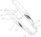
附图1:天然气水合物固态流化开采自动射流破碎工具总剖视图Figure 1: General sectional view of the automatic jet breaking tool for solid-state fluidized exploitation of natural gas hydrate
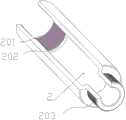
附图2:天然气水合物固态流化开采自动射流破碎工具解锁状态半剖图Figure 2: Half-section view of the unlocked state of the automatic jet breaking tool for solid-state fluidized mining of natural gas hydrate
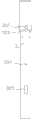
附图3:天然气水合物固态流化开采自动射流破碎工具锁定状态半剖图Figure 3: Half-section view of the locked state of the automatic jet breaking tool for solid-state fluidized exploitation of natural gas hydrate
附图4:天然气水合物固态流化开采自动射流破碎工具主视图Figure 4: Front view of the automatic jet breaking tool for solid-state fluidized exploitation of natural gas hydrate
附图5:上部接头四分之三剖视图Figure 5: Three-quarter cutaway view of the upper joint
附图6:外筒体四分之三剖视图Figure 6: Three-quarter sectional view of the outer cylinder
附图7:内滑套正视图Figure 7: Front view of inner sliding sleeve
附图8:内滑套四分之三剖视图Figure 8: Three-quarter sectional view of the inner sliding sleeve
附图9:锁止滑套主视图Figure 9: Front view of locking sliding sleeve
附图10:射流接头四分之三剖视图Figure 10: Three-quarter sectional view of the jet joint
附图11:射流喷头主视图Figure 11: Front view of jet nozzle
附图12:射流喷头剖视图Figure 12: Cross-sectional view of jet nozzle
附图13:堵塞块主视图Figure 13: Front view of the blocking block
1-上部接头;101-上部工具接口;102-导流口;103-内滑套限位口;104-上部接头螺纹;105-解锁导斜面;106-自锁导槽;107-锁定斜面;2-外筒体;201-外筒体上部螺纹;202-弹簧限位口;203-外筒体下部螺纹;3-内滑套;301-钻井液导流口;302-自锁导块;303-内滑套自锁斜面;304-压力平衡孔;305-泄流槽;306-增压流道;307-挤压型密封端面;4-锁止滑套;401-锁止滑套斜面;402-锁止滑套导槽;403-轴承槽;5-推力轴承;6-弹簧;7-射流接头;701-下接头螺纹;702-喷头孔;703-滑动通道;704-堵塞块安装螺纹;705-流道;706-轴向流孔;8-伸缩式射流喷头;801-射流喷嘴;802-喷嘴限位面;803-喷嘴弹簧限位面;804-喷嘴增压流道;805-喷嘴弹簧;806-弹簧限位块;807-射流喷头螺纹;9-堵塞块;901-密封圈安装槽;902-堵塞块螺纹;10-挤压型密封圈。1-upper joint; 101-upper tool interface; 102-guide port; 103-inner sliding sleeve limit port; 104-upper joint thread; 105-unlocking guide bevel; 106-self-locking guide groove; 107-locking bevel; 2-outer cylinder; 201-upper thread of outer cylinder; 202-spring limit port; 203-lower thread of outer cylinder; 3-inner sliding sleeve; 301-drilling fluid diversion port; 302-self-locking guide block; 303-inner sliding sleeve self-locking slope; 304-pressure balance hole; 305-relief groove; 306-pressurized flow channel; 307-extrusion sealing end face; 4-locking sliding sleeve; 401-locking sliding sleeve slope ;402-locking sliding sleeve guide groove;403-bearing groove;5-thrust bearing;6-spring;7-jet joint;701-lower joint thread;702-sprinkler hole;703-sliding channel;704-blocking block installation Thread; 705-runner; 706-axial orifice; 8-retractable jet nozzle; 801-jet nozzle; 802-nozzle limit surface; 803-nozzle spring limit surface; 804-nozzle booster flow channel; 805 -Nozzle spring; 806-spring limit block; 807-jet nozzle thread; 9-blocking block; 901-seal installation groove; 902-blocking block thread; 10-extrusion type sealing ring.
具体实施方式Detailed ways
如附图1-4所示,一种天然气水合物固态流化开采自动射流破碎工具,其特征在于:包括上部接头(1)、外筒体(2)、内滑套(3)、锁止滑套(4)、推力轴承(5)、弹簧(6)、射流接头(7)、伸缩式射流喷头(8)、堵塞块(9)、挤压型密封圈(10),上部接头(1)位于整个装置最左侧,外筒体(2)通过螺纹连接在上部接头(1)右侧,内滑套(3)安装在外筒体(2)内部,锁止滑套(4)安装在内滑套(3)外环侧,滚筒轴承(5)设置在锁止滑套(4)右侧,弹簧(6)设置滚筒轴承(5)与外筒体(2)内侧之间,射流接头(7)通过螺纹连接在外筒体(2)右侧,堵塞块(9)通过螺纹连接在射流接头(7)内部,伸缩式射流喷头(8)通过螺纹连接在射流接头(7)外表面环侧,挤压型密封圈(10)通过凹槽安装在堵塞块(9)外环侧。As shown in Figures 1-4, an automatic jet breaking tool for solid-state fluidized exploitation of natural gas hydrate is characterized in that it comprises an upper joint (1), an outer cylinder (2), an inner sliding sleeve (3), a locking Sliding sleeve (4), thrust bearing (5), spring (6), jet joint (7), telescopic jet nozzle (8), blocking block (9), extruded sealing ring (10), upper joint (1) ) is located at the far left of the whole device, the outer cylinder (2) is threaded on the right side of the upper joint (1), the inner sliding sleeve (3) is installed inside the outer cylinder (2), and the locking sliding sleeve (4) is installed in the The inner sliding sleeve (3) is on the outer ring side, the roller bearing (5) is arranged on the right side of the locking sliding sleeve (4), the spring (6) is arranged between the roller bearing (5) and the inner side of the outer cylinder (2), the jet joint (7) It is screwed to the right side of the outer cylinder (2), the plug (9) is screwed to the inside of the jet joint (7), and the telescopic jet nozzle (8) is screwed to the outer surface ring of the jet joint (7). The extruded sealing ring (10) is installed on the outer ring side of the blocking block (9) through the groove.
如附图5所示,所述上部接头(1)设计有上部工具接口(101)、导流口(102)、内滑套限位口(103)、上部接头螺纹(104)、解锁导斜面(105)、自锁导槽(106)、锁定斜面(107),上部接头螺纹(104)用于连接外筒体(2)。As shown in FIG. 5 , the upper joint (1) is designed with an upper tool interface (101), a guide port (102), an inner sliding sleeve limit port (103), an upper joint thread (104), an unlocking guide slope (105), a self-locking guide groove (106), a locking slope (107), and an upper joint thread (104) for connecting the outer cylinder (2).
如附图6所示,所示外筒体(2)设计有外筒体上部螺纹(201)、弹簧限位口(202)、外筒体下部螺纹(203),外筒体上部螺纹(201)用于连接上部接头(1),弹簧限位口(202)用于抵住弹簧(6),外筒体下部螺纹(203)用于连接下部射流接头(7)。As shown in FIG. 6 , the outer cylinder (2) shown is designed with an upper thread (201) of the outer cylinder, a spring limit opening (202), a lower thread (203) of the outer cylinder, and an upper thread (201) of the outer cylinder. ) is used to connect the upper joint (1), the spring limit port (202) is used to abut the spring (6), and the lower thread (203) of the outer cylinder is used to connect the lower jet joint (7).
如附图7-8所示,所述内滑套(3)设计有钻井液导流口(301)、自锁导块(302)、内滑套自锁斜面(303)、压力平衡孔(304)、泄流槽(305)、增压流道(306)、挤压型密封端面(307)、钻井液导流口(301)。钻井液导流口(301)使钻井液增压进入内滑套(3),增压流道(306)能够将流体的动力更多地转换为对内滑套的轴向推力,并且使得进入内滑套内部的钻井液压力更大,压力平衡孔(304)能够平衡内滑套(3)与外筒体(2)之间的压力,使得钻井液作用在内滑套(3)的轴向推力更大,泄流槽(305)的作用是当射流工具开启时,钻井液便通过泄流槽(305)流向伸缩式射流喷头(8)喷出,在内滑套(3)向下移动,射流工具处于开启状态时,挤压型密封端面(307)、挤压型密封圈(10)变形达到密封的效果。As shown in Figures 7-8, the inner sliding sleeve (3) is designed with a drilling fluid diversion port (301), a self-locking guide block (302), an inner sliding sleeve self-locking slope (303), and a pressure balance hole ( 304), a drain groove (305), a pressurized flow channel (306), an extruded sealing end face (307), and a drilling fluid diversion port (301). The drilling fluid diversion port (301) pressurizes the drilling fluid into the inner sliding sleeve (3), and the pressurized flow channel (306) can convert more power of the fluid into an axial thrust to the inner sliding sleeve, and make the drilling fluid enter the inner sliding sleeve (306). The pressure of the drilling fluid inside the inner sliding sleeve is higher, and the pressure balance hole (304) can balance the pressure between the inner sliding sleeve (3) and the outer cylinder (2), so that the drilling fluid acts on the shaft of the inner sliding sleeve (3) The thrust is larger, and the function of the drain groove (305) is that when the jet tool is turned on, the drilling fluid will flow to the telescopic jet nozzle (8) through the drain groove (305), and the inner sliding sleeve (3) will go downward. Moving, when the jet tool is in the open state, the extruded sealing end face (307) and the extruded sealing ring (10) are deformed to achieve the sealing effect.
如附图9所示,所述锁止滑套(4)均匀设置有锁止滑套斜面(401)、锁止滑套导槽(402)、轴承槽(403),推力轴承(5)防置在轴承槽(403)内,弹簧(6)一侧抵在推力轴承(5)上,另一侧抵在弹簧限位口(202)上。As shown in FIG. 9 , the locking sliding sleeve (4) is evenly provided with a locking sliding sleeve inclined surface (401), a locking sliding sleeve guide groove (402), a bearing groove (403), and the thrust bearing (5) prevents Set in the bearing groove (403), one side of the spring (6) abuts on the thrust bearing (5), and the other side abuts on the spring limit port (202).
如附图10所示,所述射流接头(7)表面设置有喷头孔(702),内部设置有下接头螺纹(701)、滑动通道(703)、堵塞块安装螺纹(704)、流道(705)、轴向流孔(706)。下接头螺纹(701)用于连接外筒体(2),喷头孔(702)用于安装伸缩式射流喷头(8),滑动通道(703)的内径和内滑套(3)下端的外径相同,两者相互配合达到密封的目的,堵塞块安装螺纹(704)用于安装堵塞块(9),流道(705)在内滑套(3)解锁状态时,可以流通钻井液,轴向流孔(706)可以使通过流道(705)的钻井液流出的扩散半径更大,起到良好的破碎钻井效果。As shown in Figure 10, the jet joint (7) is provided with a nozzle hole (702) on the surface, and a lower joint thread (701), a sliding channel (703), a blocking block mounting thread (704), a flow channel ( 705), axial flow hole (706). The lower joint thread (701) is used to connect the outer cylinder (2), the nozzle hole (702) is used to install the telescopic jet nozzle (8), the inner diameter of the sliding channel (703) and the outer diameter of the lower end of the inner sliding sleeve (3) The same, the two cooperate with each other to achieve the purpose of sealing. The plugging block installation thread (704) is used to install the plugging block (9). The flow channel (705) can flow drilling fluid when the inner sliding sleeve (3) is unlocked. The flow hole (706) can make the diffusion radius of the drilling fluid flowing out through the flow channel (705) larger, which has a good effect of breaking drilling.
如附图11-12所示,所述伸缩式射流喷头(8)设置有射流喷嘴(801)、喷嘴限位面(802)、喷嘴弹簧限位面(803)、喷嘴增压流道(804)、喷嘴弹簧(805)、弹簧限位块(806)、射流喷头螺纹(807)。其中射流喷嘴(801)内部设置有喷嘴增压流道(804),用于增加钻井液的压力,喷嘴限位面(802)的作用是在射流喷嘴(801)回弹时,抵住射流喷嘴(801),喷嘴弹簧(805)安装在射流喷嘴(801)外环侧,同时抵住喷嘴弹簧限位面(803)和弹簧限位块(806),弹簧限位块(806)通过螺纹与射流喷嘴(801)连接,当射流破碎工具处于开启状态时,钻井液从伸缩式射流喷头(8)喷出,射流喷嘴(801)在钻井液压力的作用下,克服喷嘴弹簧(805)的弹力向外伸出,使得射流破碎工具的破碎半径更大,开采效率更高,当射流破碎工具处于关闭状态时,射流喷嘴(801)没有钻井液通过,射流喷嘴(801)受到喷嘴弹簧(805)的回弹力而归位。As shown in Figures 11-12, the telescopic jet nozzle (8) is provided with a jet nozzle (801), a nozzle limit surface (802), a nozzle spring limit surface (803), and a nozzle booster flow channel (804). ), nozzle spring (805), spring stopper (806), jet nozzle thread (807). The jet nozzle (801) is provided with a nozzle booster flow channel (804) for increasing the pressure of the drilling fluid, and the function of the nozzle limit surface (802) is to press the jet nozzle (801) against the jet nozzle when the jet nozzle (801) rebounds. (801), the nozzle spring (805) is installed on the outer ring side of the jet nozzle (801), and at the same time abuts the nozzle spring limit surface (803) and the spring limit block (806). The spring limit block (806) is connected to the The jet nozzle (801) is connected. When the jet breaking tool is in the open state, the drilling fluid is ejected from the telescopic jet nozzle (8). The jet nozzle (801) overcomes the elastic force of the nozzle spring (805) under the action of the drilling fluid pressure. Extending outwards, the breaking radius of the jet breaking tool is larger, and the production efficiency is higher. When the jet breaking tool is in the closed state, the jet nozzle (801) does not pass through the drilling fluid, and the jet nozzle (801) is affected by the nozzle spring (805). the resilience and return to position.
如附图13所示,所述堵塞块(9)环侧设置有密封圈安装槽(901),下端设置有堵塞块螺纹(902),堵塞块螺纹(902)用于和堵塞块安装螺纹(704)连接,密封圈安装槽(901)用于安装挤压型密封圈(10),挤压型密封圈(10)在内滑套(3)锁定时,挤压型密封端面(307)、挤压型密封圈(10)变形达到密封的效果。As shown in FIG. 13 , a sealing ring mounting groove (901) is provided on the ring side of the blocking block (9), and a blocking block thread (902) is provided at the lower end, and the blocking block thread (902) is used for the blocking block mounting thread ( 704) connection, the sealing ring installation groove (901) is used to install the extruded sealing ring (10). When the extruded sealing ring (10) is locked in the inner sliding sleeve (3), the The extrusion type sealing ring (10) is deformed to achieve the sealing effect.
在开始钻井过程中,天然气水合物固态流化开采自动射流破碎工具初始是解锁状态,此时内滑套(3)位于较上端,内滑套(3)表面的自锁导块(302)位于上部接头(1)下端的自锁导槽(106)内,锁止滑套(4)上的锁止滑套斜面(401)也位于自锁导槽(106)内,且此时锁止滑套斜面(401)的尖端位置在内滑套(3)表面的内滑套自锁斜面(303)的二分之一处,在解锁状态下,钻井液从流道(705)通过到轴向流孔(706)流出,对天然气水合物层进行轴向破碎。当钻井液的流量增大到一定程度时,内滑套(3)收到的轴向推力增大到一定值,使得内滑套(3)克服弹簧(6)的推力向下移动,内滑套(3)表面的自锁导块(302)沿着上部接头(1)下端的自锁导槽(106)移动并最终移出自锁导槽(106)之外,当钻井液的流量增大过后又恢复较小值的时候,原本的锁止滑套斜面(401)的尖端位置在内滑套(3)表面的内滑套自锁斜面(303)的二分之一处,在没有自锁导槽(106)的约束下,锁止滑套斜面(401)的尖端位置沿着内滑套(3)表面的内滑套自锁斜面(303)下滑到内滑套自锁斜面(303)的底端,并且在钻井液的流量进一步减小时,内滑套(3)收到的轴向推力减小,锁止滑套斜面(401)沿着锁定斜面(107)滑动,最终停在锁定斜面(107)的底端,此时由于锁定斜面(107)的限制作用,即使钻井液流量减小,内滑套(3)仍然位于较下端,天然气水合物固态流化开采自动射流破碎工具处于开启状态,钻井液通过泄流槽(305)流到伸缩式射流喷头(8)喷出,对天然气水合物层进行周向破碎。当钻井液的流量又增大到一定程度时,内滑套(3)收到的轴向推力增大到一定值,使得内滑套(3)克服弹簧(6)的推力向下移动,内滑套(3)表面的自锁导块(302)沿着上部接头(1)下端的锁定斜面(107)轴向移动并最终移出锁定斜面(107)之外,当钻井液的流量增大过后又恢复较小值的时候,原本的锁止滑套斜面(401)的尖端位置在内滑套(3)表面的内滑套自锁斜面(303)的二分之一处,在没有锁定斜面(107)的约束下,锁止滑套斜面(401)的尖端位置沿着内滑套(3)表面的内滑套自锁斜面(303)下滑到内滑套自锁斜面(303)的底端,并且在钻井液的流量进一步减小时,内滑套(3)收到的轴向推力减小,锁止滑套斜面(401)沿着解锁导斜面(105)滑动,最终落入自锁导槽(106)中并沿着自锁导槽(106)滑动停在其最低端,此时内滑套(3)位于较上端,天然气水合物固态流化开采自动射流破碎工具恢复解锁状态,钻井液从流道(705)通过到轴向流孔(706)流出,对天然气水合物层进行轴向破碎。从而通过控制钻井液流量的大小来启闭天然气水合物固态流化开采自动射流破碎工具,改变其对天然气水合物层的破碎形式。During the drilling process, the automatic jet breaking tool for solid-state fluidized production of natural gas hydrate is initially unlocked. At this time, the inner sliding sleeve (3) is located at the upper end, and the self-locking guide block (302) on the surface of the inner sliding sleeve (3) is located at the upper end. In the self-locking guide groove (106) at the lower end of the upper joint (1), the locking sliding sleeve slope (401) on the locking sliding sleeve (4) is also located in the self-locking guide groove (106), and at this time the locking sliding sleeve The tip of the sleeve slope (401) is located at half of the inner sliding sleeve self-locking slope (303) on the surface of the inner sliding sleeve (3). In the unlocked state, the drilling fluid passes from the flow channel (705) to the axial direction The orifice (706) flows out and axially fractures the natural gas hydrate layer. When the flow rate of drilling fluid increases to a certain level, the axial thrust received by the inner sliding sleeve (3) increases to a certain value, so that the inner sliding sleeve (3) overcomes the thrust of the spring (6) and moves downward, and the inner sliding sleeve (3) moves downward. The self-locking guide block (302) on the surface of the casing (3) moves along the self-locking guide groove (106) at the lower end of the upper joint (1) and finally moves out of the self-locking guide groove (106), when the flow rate of drilling fluid increases When the smaller value is restored later, the tip of the original locking sliding sleeve slope (401) is located at half of the inner sliding sleeve self-locking slope (303) on the surface of the inner sliding sleeve (3). Under the constraint of the lock guide groove (106), the tip position of the locking sliding sleeve slope (401) slides down to the inner sliding sleeve self-locking slope (303) along the inner sliding sleeve self-locking slope (303) on the surface of the inner sliding sleeve (3). ), and when the flow rate of drilling fluid is further reduced, the axial thrust received by the inner sliding sleeve (3) decreases, the locking sliding sleeve slope (401) slides along the locking slope (107), and finally stops at The bottom end of the locking slope (107), at this time, due to the restriction of the locking slope (107), even if the drilling fluid flow rate decreases, the inner sliding sleeve (3) is still located at the lower end, and the automatic jet breaking tool for solid-state fluidized production of natural gas hydrate In the open state, the drilling fluid flows through the drain groove (305) to the telescopic jet nozzle (8) to be ejected, and the natural gas hydrate layer is broken in the circumferential direction. When the flow rate of drilling fluid increases to a certain level, the axial thrust received by the inner sliding sleeve (3) increases to a certain value, so that the inner sliding sleeve (3) moves downward against the thrust of the spring (6), and the inner sliding sleeve (3) moves downward. The self-locking guide block (302) on the surface of the sliding sleeve (3) moves axially along the locking slope (107) at the lower end of the upper joint (1) and finally moves out of the locking slope (107), when the flow rate of drilling fluid increases When it returns to a smaller value, the tip of the original locking sliding sleeve slope (401) is located at half of the inner sliding sleeve self-locking slope (303) on the surface of the inner sliding sleeve (3). Under the constraint of (107), the tip position of the locking sliding sleeve inclined surface (401) slides down along the inner sliding sleeve self-locking inclined surface (303) on the surface of the inner sliding sleeve (3) to the bottom of the inner sliding sleeve self-locking inclined surface (303). and when the flow rate of drilling fluid is further reduced, the axial thrust received by the inner sliding sleeve (3) decreases, the locking sliding sleeve slope (401) slides along the unlocking guide slope (105), and finally falls into the self-locking The guide groove (106) slides and stops at its lowest end along the self-locking guide groove (106), at this time the inner sliding sleeve (3) is located at the upper end, and the automatic jet breaking tool for solid-state fluidized production of natural gas hydrate returns to the unlocked state, The drilling fluid flows out from the flow channel (705) to the axial flow hole (706), and axially fractures the natural gas hydrate layer. Therefore, by controlling the flow rate of the drilling fluid, the automatic jet breaking tool for solid-state fluidization exploitation of natural gas hydrate can be opened and closed, and the breaking form of the natural gas hydrate layer can be changed.
Claims (8)
Priority Applications (2)
| Application Number | Priority Date | Filing Date | Title |
|---|---|---|---|
| CN201911087346.9ACN110700801B (en) | 2019-11-08 | 2019-11-08 | Automatic jet flow crushing tool for solid fluidization exploitation of natural gas hydrate |
| US17/079,655US11193333B2 (en) | 2019-11-08 | 2020-10-26 | Automatic jet breaking tool for solid fluidization exploitation of natural gas hydrate |
Applications Claiming Priority (1)
| Application Number | Priority Date | Filing Date | Title |
|---|---|---|---|
| CN201911087346.9ACN110700801B (en) | 2019-11-08 | 2019-11-08 | Automatic jet flow crushing tool for solid fluidization exploitation of natural gas hydrate |
Publications (2)
| Publication Number | Publication Date |
|---|---|
| CN110700801Atrue CN110700801A (en) | 2020-01-17 |
| CN110700801B CN110700801B (en) | 2020-05-12 |
Family
ID=69205510
Family Applications (1)
| Application Number | Title | Priority Date | Filing Date |
|---|---|---|---|
| CN201911087346.9AActiveCN110700801B (en) | 2019-11-08 | 2019-11-08 | Automatic jet flow crushing tool for solid fluidization exploitation of natural gas hydrate |
Country Status (2)
| Country | Link |
|---|---|
| US (1) | US11193333B2 (en) |
| CN (1) | CN110700801B (en) |
Cited By (8)
| Publication number | Priority date | Publication date | Assignee | Title |
|---|---|---|---|---|
| CN112282707A (en)* | 2020-12-18 | 2021-01-29 | 福州大学 | Sea natural gas hydrate barrel type mining device and method thereof |
| CN112343557A (en)* | 2020-12-18 | 2021-02-09 | 福州大学 | Sea area natural gas hydrate self-entry mining device and mining method |
| CN113027254A (en)* | 2021-04-12 | 2021-06-25 | 无锡忻润汽车安全系统有限公司 | Hidden type automobile outer door handle mounting structure and mounting method |
| CN113107435A (en)* | 2021-04-29 | 2021-07-13 | 南方海洋科学与工程广东省实验室(湛江) | Internal and external linkage type jet crushing tool for natural gas hydrate |
| CN113107436A (en)* | 2021-04-29 | 2021-07-13 | 南方海洋科学与工程广东省实验室(湛江) | Underground self-locking safety valve for deep-sea natural gas hydrate double-layer pipe exploitation |
| CN113137209A (en)* | 2021-04-27 | 2021-07-20 | 中国地质科学院勘探技术研究所 | Drilling and injection integrated marine natural gas hydrate reservoir transformation appliance and method |
| CN114370235A (en)* | 2022-01-13 | 2022-04-19 | 中国石油大学(北京) | Adjustable constant firing rate rock breaking sprinkler |
| CN116122757A (en)* | 2021-11-15 | 2023-05-16 | 中国石油天然气集团有限公司 | Hydraulic drilling, grinding and flushing tool integrated tool |
Families Citing this family (6)
| Publication number | Priority date | Publication date | Assignee | Title |
|---|---|---|---|---|
| CN113279731B (en)* | 2021-06-04 | 2022-06-14 | 西南石油大学 | A premixed abrasive jet tool for in-situ sand separation using natural gas hydrate |
| CN113338869B (en)* | 2021-06-25 | 2022-11-25 | 长江大学 | Deepwater combustible ice settlement sand prevention mining device |
| CN114135267B (en)* | 2021-11-29 | 2023-05-05 | 西南石油大学 | Three-phase separation device for solid fluidization exploitation of natural gas hydrate |
| CN115726742B (en)* | 2022-12-20 | 2023-07-21 | 西南石油大学 | A natural gas hydrate-shallow gas-deep gas multi-source and multi-method combined production system and method |
| CN117780256B (en)* | 2023-12-29 | 2024-10-22 | 北京贝威通能源科技集团有限公司 | Bending tool for ultra-short radius horizontal well of coiled tubing drill |
| CN119221875B (en)* | 2024-10-16 | 2025-09-02 | 西南石油大学 | Deep-sea methane hydrate mining and carbon dioxide storage integrated operation tools and methods |
Citations (9)
| Publication number | Priority date | Publication date | Assignee | Title |
|---|---|---|---|---|
| US6168213B1 (en)* | 1997-06-27 | 2001-01-02 | Schlumberger Technology Corporation | Connector and connection method |
| CN202249987U (en)* | 2011-09-15 | 2012-05-30 | 中国石油天然气股份有限公司 | Anti-sulfur-slip ejector |
| CN102536187A (en)* | 2012-02-24 | 2012-07-04 | 中国石油大学(北京) | Switchable hydraulic jet fracturing underground device with combined slide sleeves |
| CN202745847U (en)* | 2012-07-26 | 2013-02-20 | 中国石油天然气股份有限公司 | Controllable hydraulic ejector |
| CN105201476A (en)* | 2014-06-16 | 2015-12-30 | 中国石油化工股份有限公司 | Sliding sleeve type hydraulic jetting device and pipe column with sliding sleeve type hydraulic jetting devices |
| CN108678671A (en)* | 2018-07-24 | 2018-10-19 | 西南石油大学 | A kind of sea bed gas hydrate digging sleeve type injection retracting device |
| US20180347325A1 (en)* | 2017-06-06 | 2018-12-06 | Sergio F. Goyeneche | Electromechanical Assembly for Routing Electrical Signals in Guns for Well Perforation |
| CN208734279U (en)* | 2018-07-11 | 2019-04-12 | 中国地质科学院勘探技术研究所 | A kind of loose overburden pipe-following drilling liquid pushing-type reamer |
| CN110005379A (en)* | 2019-05-28 | 2019-07-12 | 西南石油大学 | A kind of gas hydrate layer jet crushing pressure control sliding sleeve nozzle |
Family Cites Families (1)
| Publication number | Priority date | Publication date | Assignee | Title |
|---|---|---|---|---|
| GB2555830B (en)* | 2016-11-11 | 2020-02-05 | M I Drilling Fluids Uk Ltd | Valve assembly and method of controlling fluid flow in an oil, gas or water well |
- 2019
- 2019-11-08CNCN201911087346.9Apatent/CN110700801B/enactiveActive
- 2020
- 2020-10-26USUS17/079,655patent/US11193333B2/enactiveActive
Patent Citations (9)
| Publication number | Priority date | Publication date | Assignee | Title |
|---|---|---|---|---|
| US6168213B1 (en)* | 1997-06-27 | 2001-01-02 | Schlumberger Technology Corporation | Connector and connection method |
| CN202249987U (en)* | 2011-09-15 | 2012-05-30 | 中国石油天然气股份有限公司 | Anti-sulfur-slip ejector |
| CN102536187A (en)* | 2012-02-24 | 2012-07-04 | 中国石油大学(北京) | Switchable hydraulic jet fracturing underground device with combined slide sleeves |
| CN202745847U (en)* | 2012-07-26 | 2013-02-20 | 中国石油天然气股份有限公司 | Controllable hydraulic ejector |
| CN105201476A (en)* | 2014-06-16 | 2015-12-30 | 中国石油化工股份有限公司 | Sliding sleeve type hydraulic jetting device and pipe column with sliding sleeve type hydraulic jetting devices |
| US20180347325A1 (en)* | 2017-06-06 | 2018-12-06 | Sergio F. Goyeneche | Electromechanical Assembly for Routing Electrical Signals in Guns for Well Perforation |
| CN208734279U (en)* | 2018-07-11 | 2019-04-12 | 中国地质科学院勘探技术研究所 | A kind of loose overburden pipe-following drilling liquid pushing-type reamer |
| CN108678671A (en)* | 2018-07-24 | 2018-10-19 | 西南石油大学 | A kind of sea bed gas hydrate digging sleeve type injection retracting device |
| CN110005379A (en)* | 2019-05-28 | 2019-07-12 | 西南石油大学 | A kind of gas hydrate layer jet crushing pressure control sliding sleeve nozzle |
Cited By (9)
| Publication number | Priority date | Publication date | Assignee | Title |
|---|---|---|---|---|
| CN112282707A (en)* | 2020-12-18 | 2021-01-29 | 福州大学 | Sea natural gas hydrate barrel type mining device and method thereof |
| CN112343557A (en)* | 2020-12-18 | 2021-02-09 | 福州大学 | Sea area natural gas hydrate self-entry mining device and mining method |
| CN113027254A (en)* | 2021-04-12 | 2021-06-25 | 无锡忻润汽车安全系统有限公司 | Hidden type automobile outer door handle mounting structure and mounting method |
| CN113137209A (en)* | 2021-04-27 | 2021-07-20 | 中国地质科学院勘探技术研究所 | Drilling and injection integrated marine natural gas hydrate reservoir transformation appliance and method |
| CN113107435A (en)* | 2021-04-29 | 2021-07-13 | 南方海洋科学与工程广东省实验室(湛江) | Internal and external linkage type jet crushing tool for natural gas hydrate |
| CN113107436A (en)* | 2021-04-29 | 2021-07-13 | 南方海洋科学与工程广东省实验室(湛江) | Underground self-locking safety valve for deep-sea natural gas hydrate double-layer pipe exploitation |
| CN113107436B (en)* | 2021-04-29 | 2022-04-08 | 南方海洋科学与工程广东省实验室(湛江) | Self-locking safety valve for deep sea gas hydrate double-pipe mining |
| CN116122757A (en)* | 2021-11-15 | 2023-05-16 | 中国石油天然气集团有限公司 | Hydraulic drilling, grinding and flushing tool integrated tool |
| CN114370235A (en)* | 2022-01-13 | 2022-04-19 | 中国石油大学(北京) | Adjustable constant firing rate rock breaking sprinkler |
Also Published As
| Publication number | Publication date |
|---|---|
| US20210140243A1 (en) | 2021-05-13 |
| US11193333B2 (en) | 2021-12-07 |
| CN110700801B (en) | 2020-05-12 |
Similar Documents
| Publication | Publication Date | Title |
|---|---|---|
| CN110700801A (en) | Automatic jet flow crushing tool for solid fluidization exploitation of natural gas hydrate | |
| CN110080726B (en) | A double-tube rotary shaft pressure-controlled once-through injector for natural gas hydrate exploitation | |
| CN108678671B (en) | A sliding-sleeve jet recovery device for submarine natural gas hydrate mining | |
| CN108425661B (en) | Coiled tubing steel particle jet perforating device | |
| CN111779464B (en) | Double-layer pipe double-gradient pressure control drilling underground blowout preventer | |
| CN110005379A (en) | A kind of gas hydrate layer jet crushing pressure control sliding sleeve nozzle | |
| US20220268132A1 (en) | Cavity creation tool by crushing with multi-stage controllable water jet for natural gas hydrate development | |
| CN103470242B (en) | A kind of oilfield horizontal well volume fracturing method | |
| CN101250983B (en) | Single-pipe all-round drilling jet grouting bit capable of opening and closing auxiliary grouting holes by hydraulic control | |
| CN111456681B (en) | Double-layer in-pipe blowout prevention valve | |
| CN202325434U (en) | Closable balancing sieve tube for horizontal wells and closing tool for closable balancing sieve tube | |
| CN113107436B (en) | Self-locking safety valve for deep sea gas hydrate double-pipe mining | |
| CN207436993U (en) | Tripping in flow string bottom calker with pressure | |
| CN104196492B (en) | A kind of dragging down-hole plugging valve with pressure | |
| CN113445962B (en) | Hydraulic double-layer pipe double-gradient downhole blowout prevention valve | |
| CN210289632U (en) | High-energy hydraulic down-the-hole hammer jet reaming device for hot dry rock | |
| CN201202430Y (en) | Boring tool inner blowout preventer | |
| CN204200163U (en) | A kind of with the auxiliary leak stoppage tool of brill | |
| CN202745847U (en) | Controllable hydraulic ejector | |
| CN111894559B (en) | Inner channel decompression restrictor | |
| CN204941345U (en) | A kind of radial well transfer with packing function | |
| CN218376383U (en) | Positioning control valve | |
| CN116607884A (en) | Multi-start hydraulic reamer while drilling | |
| CN213684064U (en) | Oil layer hot washing double-protection device | |
| CN203769669U (en) | Surge pressure control nipple |
Legal Events
| Date | Code | Title | Description |
|---|---|---|---|
| PB01 | Publication | ||
| PB01 | Publication | ||
| SE01 | Entry into force of request for substantive examination | ||
| SE01 | Entry into force of request for substantive examination | ||
| GR01 | Patent grant | ||
| GR01 | Patent grant | ||
| OL01 | Intention to license declared | ||
| OL01 | Intention to license declared |