CN110693628A - An adjustable sheath tube and inferior vena cava filter delivery device - Google Patents
An adjustable sheath tube and inferior vena cava filter delivery deviceDownload PDFInfo
- Publication number
- CN110693628A CN110693628ACN201910858389.6ACN201910858389ACN110693628ACN 110693628 ACN110693628 ACN 110693628ACN 201910858389 ACN201910858389 ACN 201910858389ACN 110693628 ACN110693628 ACN 110693628A
- Authority
- CN
- China
- Prior art keywords
- sheath tube
- wire
- channel
- filter
- tube body
- Prior art date
- Legal status (The legal status is an assumption and is not a legal conclusion. Google has not performed a legal analysis and makes no representation as to the accuracy of the status listed.)
- Granted
Links
- 210000001631vena cava inferiorAnatomy0.000titleclaimsabstractdescription14
- 210000004204blood vesselAnatomy0.000claimsabstractdescription9
- 239000011229interlayerSubstances0.000claimsabstractdescription8
- 230000009471actionEffects0.000claimsabstractdescription7
- 239000000463materialSubstances0.000claimsabstractdescription5
- 230000001105regulatory effectEffects0.000claimsabstract4
- 238000011084recoveryMethods0.000claimsdescription8
- 238000010586diagramMethods0.000description8
- 208000010378Pulmonary EmbolismDiseases0.000description4
- 208000007536ThrombosisDiseases0.000description4
- 230000003068static effectEffects0.000description4
- 238000005452bendingMethods0.000description3
- 210000003111iliac veinAnatomy0.000description3
- 206010051055Deep vein thrombosisDiseases0.000description2
- 206010047249Venous thrombosisDiseases0.000description2
- 238000000034methodMethods0.000description2
- 230000004048modificationEffects0.000description2
- 238000012986modificationMethods0.000description2
- 230000004088pulmonary circulationEffects0.000description2
- 238000001356surgical procedureMethods0.000description2
- 210000003462veinAnatomy0.000description2
- 208000006193Pulmonary infarctionDiseases0.000description1
- 206010042434Sudden deathDiseases0.000description1
- 230000001174ascending effectEffects0.000description1
- 230000009286beneficial effectEffects0.000description1
- 230000000903blocking effectEffects0.000description1
- 210000001124body fluidAnatomy0.000description1
- 210000005242cardiac chamberAnatomy0.000description1
- 230000008859changeEffects0.000description1
- 201000010099diseaseDiseases0.000description1
- 208000037265diseases, disorders, signs and symptomsDiseases0.000description1
- 238000006073displacement reactionMethods0.000description1
- 229940079593drugDrugs0.000description1
- 239000003814drugSubstances0.000description1
- 230000004064dysfunctionEffects0.000description1
- 230000036541healthEffects0.000description1
- 238000002513implantationMethods0.000description1
- 208000014674injuryDiseases0.000description1
- 230000004796pathophysiological changeEffects0.000description1
- 230000000149penetrating effectEffects0.000description1
- 230000002093peripheral effectEffects0.000description1
- 210000001147pulmonary arteryAnatomy0.000description1
- 230000007575pulmonary infarctionEffects0.000description1
- 230000007704transitionEffects0.000description1
- 230000008733traumaEffects0.000description1
Images


Classifications
- A—HUMAN NECESSITIES
- A61—MEDICAL OR VETERINARY SCIENCE; HYGIENE
- A61F—FILTERS IMPLANTABLE INTO BLOOD VESSELS; PROSTHESES; DEVICES PROVIDING PATENCY TO, OR PREVENTING COLLAPSING OF, TUBULAR STRUCTURES OF THE BODY, e.g. STENTS; ORTHOPAEDIC, NURSING OR CONTRACEPTIVE DEVICES; FOMENTATION; TREATMENT OR PROTECTION OF EYES OR EARS; BANDAGES, DRESSINGS OR ABSORBENT PADS; FIRST-AID KITS
- A61F2/00—Filters implantable into blood vessels; Prostheses, i.e. artificial substitutes or replacements for parts of the body; Appliances for connecting them with the body; Devices providing patency to, or preventing collapsing of, tubular structures of the body, e.g. stents
- A61F2/01—Filters implantable into blood vessels
Landscapes
- Health & Medical Sciences (AREA)
- Cardiology (AREA)
- Oral & Maxillofacial Surgery (AREA)
- Transplantation (AREA)
- Engineering & Computer Science (AREA)
- Biomedical Technology (AREA)
- Heart & Thoracic Surgery (AREA)
- Vascular Medicine (AREA)
- Life Sciences & Earth Sciences (AREA)
- Animal Behavior & Ethology (AREA)
- General Health & Medical Sciences (AREA)
- Public Health (AREA)
- Veterinary Medicine (AREA)
- Surgical Instruments (AREA)
Abstract
Translated fromChineseDescription
Translated fromChinese技术领域technical field
本发明涉及医疗器械技术领域,具体涉及一种可调弯鞘管及下腔静脉滤器输送装置。The invention relates to the technical field of medical devices, in particular to an adjustable sheath tube and an inferior vena cava filter delivery device.
背景技术Background technique
肺动脉栓塞(简称肺栓塞pulmonary embolism,PE)是由于周围深静脉血栓或右心腔的血栓脱落进入肺循环,堵塞肺动脉或其分支,进而引发的一系列以肺循环功能障碍为主的临床病理生理改变,严重的会引起猝死。研究表明,引起PE发生的栓子主要来源于肢体深静脉或盆腔静脉脱落的血栓,占栓子来源的60%~90%。由此深静脉血栓形成已成为危害人类健康的常见病,发病率逐年上升,重要的并发症是血栓反复脱落,导致肺动脉栓塞和肺梗死,死亡率极高,严重危及病人的生命。采用传统手术治疗,创伤面较大,危险性大,近几年来采用介入治疗,经皮下腔静脉滤器植入术是采用经皮穿刺的方法,通过鞘管输送器,在下腔静脉放置金属滤器,滤器可以阻止血栓上行,预防或减少肺动脉血栓栓塞。与传统的外科手术相比,经皮下腔静脉滤器置放术简单、安全、有效,近年来已被广泛采用。Pulmonary embolism (pulmonary embolism, PE) is a series of clinical pathophysiological changes mainly caused by pulmonary circulation dysfunction caused by peripheral deep vein thrombosis or right heart chamber thrombus falling off into the pulmonary circulation and blocking the pulmonary artery or its branches. Severe cases can cause sudden death. Studies have shown that the emboli that cause PE mainly come from the thrombus shed from the deep veins of the limbs or the pelvic vein, accounting for 60% to 90% of the source of the emboli. As a result, deep vein thrombosis has become a common disease that endangers human health, and the incidence is increasing year by year. The important complication is repeated thrombus shedding, leading to pulmonary embolism and pulmonary infarction. The mortality rate is extremely high and the patient's life is seriously endangered. Using traditional surgical treatment, the trauma surface is large and the risk is high. In recent years, interventional treatment has been adopted. Percutaneous vena cava filter implantation is a method of percutaneous puncture. The filter can stop the thrombus from ascending, preventing or reducing pulmonary thromboembolism. Compared with traditional surgical procedures, percutaneous vena cava filter placement is simple, safe, and effective, and has been widely used in recent years.
在上述的微创介入治疗手术中常采用医用鞘管来建立腔静脉滤器自体外向体内的输送通道。目前已在临床投入使用的各类用于腔静脉滤器输送的鞘管均为直线型,当鞘管在血管内走行时,由于血管的自然生理弯曲,导致鞘管受到血管的作用力而使其远端无法位于腔静脉的中心,该问题导致了在滤器释放时,滤器无法沿腔静脉长轴准确释放,进而可能导致滤器固定不稳定,从而导致后期滤器移位、贴壁、穿破静脉壁等并发症发生。如果在滤器输送过程中,能对鞘管的远端的方向进行调节和控制,使其移动至目标位置后能准确位于腔静脉长轴方向,可有效增加滤器释放的成功率,并减少并发症发生率。In the above-mentioned minimally invasive interventional treatment operations, a medical sheath is often used to establish a delivery channel for the vena cava filter from the outside to the inside of the body. At present, all kinds of sheath tubes used for vena cava filter delivery in clinical use are all straight. When the sheath tube runs in the blood vessel, due to the natural physiological bending of the blood vessel, the sheath tube is subjected to the force of the blood vessel. The distal end cannot be located in the center of the vena cava. This problem results in that the filter cannot be accurately released along the long axis of the vena cava when the filter is released, which may lead to unstable filter fixation, resulting in later filter displacement, adherence, and perforation of the venous wall. Complications occur. If the direction of the distal end of the sheath can be adjusted and controlled during the delivery of the filter, so that it can be accurately positioned in the direction of the long axis of the vena cava after moving to the target position, which can effectively increase the success rate of filter release and reduce complications. incidence.
现有技术中的可调弯鞘管虽然也可调节鞘管远端弯曲角度,但是现有技术都是固定鞘管远端某一点位置,在鞘管近端用牵引丝拉动鞘管远端时,往往使得鞘管的端部首先弯曲,然后慢慢带动后面的一段做弧形过渡弯曲,无法实现滤器输送功能。因此,现有技术并不能满足上述平行放置滤器的需求。Although the adjustable sheath tube in the prior art can also adjust the bending angle of the distal end of the sheath tube, the prior art is to fix a certain position of the distal end of the sheath tube. , often make the end of the sheath bend first, and then slowly drive the latter section to make an arc transition bending, which cannot realize the filter delivery function. Therefore, the prior art cannot meet the above-mentioned requirement of placing filters in parallel.
如何解决释放滤器不能与下腔静脉平行的问题,是目前本领域技术人员急需解决的问题。How to solve the problem that the release filter cannot be parallel to the inferior vena cava is an urgent problem to be solved by those skilled in the art.
发明内容SUMMARY OF THE INVENTION
本发明的目的在于提供一种可调弯鞘管及下腔静脉滤器输送装置,使其可以在下腔静脉长轴中心线的位置释放滤器,从而提高滤器释放的安全性及有效性。The purpose of the present invention is to provide an adjustable sheath tube and an inferior vena cava filter delivery device, which can release the filter at the position of the center line of the long axis of the inferior vena cava, thereby improving the safety and effectiveness of the filter release.
为实现上述目的,本发明主要提供如下技术方案:For achieving the above object, the present invention mainly provides the following technical solutions:
一方面,本发明提供一种可调弯鞘管,包括鞘管管体、调节丝和调节器,其中,In one aspect, the present invention provides an adjustable sheath, comprising a sheath body, an adjustment wire and an adjuster, wherein,
所述鞘管管体为柔性材料,其进入体内后在导丝的作用下可随血管走向弯曲;所述鞘管管体的近端外露于体外且与所述调节器固定连接;The sheath tube body is a flexible material, which can be bent along the direction of the blood vessel under the action of the guide wire after entering the body; the proximal end of the sheath tube body is exposed outside the body and is fixedly connected with the regulator;
所述鞘管管体的管壁夹层内设有沿其长度方向贯通的通道,所述调节丝从所述通道的近端穿入,到达所述通道的远端并与设置在所述鞘管管体远端的固定段固定,所述调节丝沿所述固定段的长度与之整段固定,所述固定段在自然状态下呈直线状态;The tube wall interlayer of the sheath tube body is provided with a channel passing through along its length direction, the adjustment wire penetrates from the proximal end of the channel, reaches the distal end of the channel, and is connected with the sheath tube. The fixed section at the distal end of the tube body is fixed, the adjustment wire is fixed to the entire section along the length of the fixed section, and the fixed section is in a straight state in a natural state;
所述调节丝的近端与所述调节器的调节单元连接,所述调节丝在所述调节单元的拉动下使所述固定段整体偏斜一个角度。The proximal end of the adjustment wire is connected with the adjustment unit of the adjuster, and the adjustment wire makes the entire fixed section deflect an angle under the pulling of the adjustment unit.
优选地,所述调节丝为两根以上,并沿所述鞘管管体的截面中心对称分布于所述鞘管管体的管壁中。Preferably, there are more than two adjusting wires, which are symmetrically distributed in the tube wall of the sheath tube body along the cross-sectional center of the sheath tube body.
优选地,还包括连接器,所述连接器至少包括互相连通的三个通路;其中,第一通路与所述鞘管管体连接,第二通路与所述调节器连接,所述调节丝从所述第一通路进入所述第二通路并与所述调节单元连接。Preferably, a connector is also included, and the connector includes at least three passages that communicate with each other; wherein, the first passage is connected with the sheath tube body, the second passage is connected with the regulator, and the adjusting wire is connected from the The first passage enters the second passage and is connected with the adjustment unit.
优选地,所述第一通路、第二通路和第三通路形成Y型或T型结构。Preferably, the first via, the second via and the third via form a Y-shaped or T-shaped structure.
优选地,所述调节器为手动或自动控制。Preferably, the regulator is manually or automatically controlled.
优选地,所述调节器包括自锁装置。Preferably, the regulator includes a self-locking device.
另一方面,本发明还提供一种下腔静脉滤器输送装置,其包括上述的可调弯鞘管、滤器和滤器释放单元;所述滤器释放单元携带所述滤器从所述可调弯鞘管的管腔沿从近端到远端的方向送入体内并释放。In another aspect, the present invention also provides an inferior vena cava filter delivery device, comprising the above-mentioned flexible sheath, a filter and a filter release unit; the filter release unit carries the filter from the flexible sheath The lumen is fed into the body in a proximal-to-distal direction and released.
优选地,所述滤器还包括回收钩,所述回收钩设置在所述滤器的尾端。Preferably, the filter further includes a recovery hook, and the recovery hook is provided at the rear end of the filter.
有益效果:Beneficial effects:
本发明的技术方案通过在所述鞘管管体的管壁夹层内设置沿其长度方向贯通的通道,使所述调节丝从所述通道的近端穿入,到达所述通道的远端并与设置在所述鞘管管体远端的固定段固定,所述调节丝沿所述固定段的长度与之整段固定,由于所述固定段是一段直线段,不同于一个点,因此所述调节丝与整个所述固定段固定时,会使所述固定段在自然状态下仍然呈直线状态,同时由于所述调节丝的近端与所述调节器的调节单元连接,因此所述调节丝在所述调节单元的拉动下能够使所述固定段整体与其它与之相连的鞘管部分偏斜一个角度,因此可以实现所述鞘管管体在左、右髂静脉汇合处上行折弯后到达下腔静脉进行静脉滤器释放时处于与腔静脉长轴平行的状态,从而保证了滤器被释放后能够沿正确的方向放置,使腔静脉滤器释放时获得最佳的固定位置。The technical solution of the present invention is to provide a channel running through the length direction of the sheath tube body in the tube wall interlayer, so that the adjustment wire penetrates from the proximal end of the channel, reaches the distal end of the channel, and It is fixed with the fixed section arranged at the distal end of the sheath tube body, and the adjustment wire is fixed with the entire section along the length of the fixed section. Since the fixed section is a straight section, different from a point, the When the adjustment wire is fixed with the entire fixed section, the fixed section is still in a straight state in a natural state. At the same time, because the proximal end of the adjustment wire is connected with the adjustment unit of the Under the pulling of the adjusting unit, the wire can make the whole of the fixed section and other sheath parts connected to it deflect an angle, so the sheath tube body can be bent upward at the confluence of the left and right iliac veins. After reaching the inferior vena cava to release the vena cava filter, it is in a state parallel to the long axis of the vena cava, so as to ensure that the filter can be placed in the correct direction after being released, so that the vena cava filter can obtain the best fixed position when it is released.
上述说明仅是本发明技术方案的概述,为了能够更清楚了解本发明的技术手段,并可依照说明书的内容予以实施,以下以本发明的较佳实施例并配合附图详细说明如后。The above description is only an overview of the technical solution of the present invention. In order to understand the technical means of the present invention more clearly, and implement it according to the content of the description, the preferred embodiments of the present invention are described in detail below with the accompanying drawings.
附图说明Description of drawings
图1为本发明的一个实施例提出的一种可调弯鞘管的整体结构示意图;1 is a schematic diagram of the overall structure of an adjustable sheath tube proposed by an embodiment of the present invention;
图2为本发明的一个实施例提出的一种可调弯鞘管的截面结构示意图;2 is a schematic cross-sectional structure diagram of an adjustable sheath tube proposed by an embodiment of the present invention;
图3为本发明的一个实施例提出的一种可调弯鞘管的另一种实现方式的结构示意图;3 is a schematic structural diagram of another implementation manner of an adjustable sheath tube proposed by an embodiment of the present invention;
图4为图3的拆解结构示意图;Fig. 4 is the dismantling structure schematic diagram of Fig. 3;
图5为图3结构中的固定段在拉力作用下倾斜的状态图;Fig. 5 is the state diagram that the fixed section in the structure of Fig. 3 is inclined under the action of pulling force;
图6为本发明的一个实施例提出的一种可调弯鞘管的具体应用示意图;6 is a schematic diagram of a specific application of an adjustable sheath proposed by an embodiment of the present invention;
图7为本发明的另一个实施例提出的一种下腔静脉滤器输送装置的结构示意图。FIG. 7 is a schematic structural diagram of an inferior vena cava filter delivery device according to another embodiment of the present invention.
附图标记如下:The reference numbers are as follows:
鞘管管体10、通道11、固定段12;调节丝20;调节器30、调节单元31、导槽32、旋筒33、端盖34、支柱35、刻度331;连接器40、第一通路 41、第二通路42、第三通路43;滤器1;可调弯鞘管2;滤器释放单元3;回收钩4。
具体实施方式Detailed ways
以下实施例用于说明本发明,但不用来限制本发明的范围。若未特别指明,实施例中所用的技术手段为本领域技术人员所熟知的常规手段。The following examples are intended to illustrate the present invention, but not to limit the scope of the present invention. Unless otherwise specified, the technical means used in the examples are conventional means well known to those skilled in the art.
实施例1Example 1
如图1至图6所示,本发明的一个实施例提供一种可调弯鞘管,包括鞘管管体10、调节丝20和调节器30。其中,所述鞘管管体10为柔性材料,其管体包括中空的管腔,导丝从所述管腔穿过引导所述鞘管管体10进入体内并在导丝的作用下所述鞘管管体10可随血管走向弯曲,沿着血管壁前进。所述鞘管管体10的近端外露于体外且与所述调节器30固定连接,方便操作者操作。下面以操作者的位置为准,离操作者较远的一端称为远端,离操作者较近的一端称为近端。As shown in FIGS. 1 to 6 , an embodiment of the present invention provides an adjustable sheath, including a
所述鞘管管体10的管壁夹层内设有沿其长度方向贯通的通道11,所述调节丝20从所述通道11的近端穿入,到达所述通道11的远端并与设置在所述鞘管管体10远端的固定段12固定,所述调节丝20与整个所述固定段12固定,使所述固定段12在自然状态下呈直线状态。The
如图4所示,所述调节丝20的近端与所述调节器30的调节单元31连接,所述调节丝20在所述调节单元31的拉动下使所述固定段12整体偏斜一个角度(如图5所示)。所述调节丝20的拉力解除时,所述鞘管管体10 在其本身的弹性作用下能够恢复自然状态。As shown in FIG. 4 , the proximal end of the
本发明的技术方案通过在所述鞘管管体的管壁夹层内设置沿其长度方向贯通的通道,使所述调节丝从所述通道的近端穿入,到达所述通道的远端并与设置在所述鞘管管体远端的固定段固定,所述调节丝沿所述固定段的长度与之整段固定,由于所述固定段是一段直线段,不同于一个点,因此所述调节丝与整个所述固定段固定时,会使所述固定段在自然状态下仍然呈直线状态,同时由于所述调节丝的近端与所述调节器的调节单元连接,因此所述调节丝在所述调节单元的拉动下能够使所述固定段整体与其它与之相连的鞘管部分偏斜一个角度,因此可以实现所述鞘管管体在左、右髂静脉汇合处上行折弯后到达下腔静脉进行静脉滤器释放时处于与腔静脉长轴平行的状态,从而保证了滤器被释放后能够沿正确的方向放置,使腔静脉滤器释放时获得最佳的固定位置。The technical solution of the present invention is to provide a channel running through the length direction of the sheath tube body in the tube wall interlayer, so that the adjustment wire penetrates from the proximal end of the channel, reaches the distal end of the channel, and It is fixed with the fixed section arranged at the distal end of the sheath tube body, and the adjustment wire is fixed with the entire section along the length of the fixed section. Since the fixed section is a straight section, different from a point, the When the adjustment wire is fixed with the entire fixed section, the fixed section is still in a straight state in a natural state. At the same time, because the proximal end of the adjustment wire is connected with the adjustment unit of the Under the pulling of the adjusting unit, the wire can make the whole of the fixed section and other sheath parts connected to it deflect an angle, so the sheath tube body can be bent upward at the confluence of the left and right iliac veins. After reaching the inferior vena cava to release the vena cava filter, it is in a state parallel to the long axis of the vena cava, so as to ensure that the filter can be placed in the correct direction after being released, so that the vena cava filter can obtain the best fixed position when it is released.
在一优选实施例中,为了便于操作,所述调节丝20可以为两根以上,两根以上的调节丝20沿所述鞘管管体10的截面中心对称分布于所述鞘管管体10的管壁中。如图2所示为两根调节丝20时的截面分布图。In a preferred embodiment, in order to facilitate the operation, the number of the
在一优选实施例中,如图3、图4和图5所示,还可以包括连接器40,所述连接器40至少包括三个通路,且互相连通。其中,如图4所示,第一通路41与所述鞘管管体10连接,第二通路42与所述调节器30连接,所述调节丝20从所述第一通路41进入所述第二通路42并与所述调节单元31连接。如图3、图4和图5所示为所述连接器40包括三个通路的情况。其中第三通路43可以用来输送或回收器械、输入药物或导出体液等。In a preferred embodiment, as shown in FIG. 3 , FIG. 4 and FIG. 5 , a
所述调节器30的一种具体实现方式是,如图3、图4和图5所示,调节器30包括旋筒33、支柱35、导槽32、端盖34。操纵旋筒33可以带动调节丝20并改变固定段12的倾斜度,如图5所示。A specific implementation of the
所述连接器40的所述第二通路42端与所述支柱35轴向连接,沿着所述支柱35的轴线设置一个导槽32,优选导槽32的长度占所述支柱35长度的30%~90%,所述导槽32可以是穿透所述支柱35的相对两侧而形成狭长的框状。图3-图5所示的所述调节单元31为一锁控滑块,其置于所述导槽32内,且可沿所述导槽32平移。所述旋筒33套在所述导槽32上,旋筒 33与所述锁控滑块之间通过螺纹连接。旋筒33可以套在所述支柱35上自由转动并且将所述导槽32封闭。在所述支柱35的末端固定有一个端盖34,防止旋筒33脱离所述支柱35,但不妨碍旋筒33的自由转动。设置在鞘管管体10中的调节丝20的一端从鞘管管体10的侧壁穿出后,与所述锁控滑块连接。锁控滑块安装于导槽32内,锁控滑块表面具有齿牙。旋筒33的内壁上设有与锁控滑块的齿牙匹配的螺旋形的齿槽,锁控滑块由转动的旋筒 33驱动做直线往复运动,拉动与锁控滑块连接的调节丝20,使鞘管管体10 的固定段12整体发生倾斜。The end of the
在旋筒33的侧表面可以制作刻度331(比如点、线或其它符号),用于指示锁控滑块在导槽32中的位置。为了从不同方向都能观察到刻度331,每一个刻度331最好以圆周状分布于旋筒33的侧表面。A scale 331 (such as dots, lines or other symbols) can be made on the side surface of the
优选地,当刻度331与旋筒22的齿槽的螺距对应时,锁控滑块移动一个刻度,旋筒33刚好旋转一圈,使操作更方便。可选地,螺距是刻度331 的间距的整数倍时,可以更精确地观测锁控滑块移动的距离。Preferably, when the
在一优选实施例中,所述第一通路41、第二通路42和第三通路43可以形成Y型或T型结构但并不局限于此。In a preferred embodiment, the first via 41 , the second via 42 and the third via 43 may form a Y-shaped or T-shaped structure but are not limited thereto.
在一优选实施例中,所述调节器30可以为手动或自动控制。如图1为手动拨动控制的方式,图3-图5所示为手动旋转旋筒33的控制方式。还可以设计成自动控制的方式,例如使所述调节单元31通过开关的方式拉动调节丝20,达到所需的状态。In a preferred embodiment, the
在一优选实施例中,所述调节器30可以包括自锁装置。例如,图3和图4所示的结构中,根据公知的斜面摩擦静力学分析,对于齿牙与齿槽之间的最大静摩擦系数μ,只要旋筒33的内径D和齿槽的螺距d满足物理关系式:d<πμD,则调节丝20中的拉力会使齿牙与齿槽之间保持静摩擦状态,此时,旋筒33和锁控滑块都静止平衡,这就是自锁状态。当鞘管管体10的固定段12倾斜到所需的状态时,操作者可以直接松开旋筒33,而所述固定段12的倾斜角保持不变,不需要其它辅助动作就能实现自锁功能,这非常便于医生同时操作其它配套的器械。当外力转动旋筒33,打破齿牙与齿槽之间的静摩擦平衡,就能改变管体的固定段12的倾斜角。不受外力的旋筒 33在任意位置都有自锁功能,而且转动旋筒33就能随时解除自锁,这给手术操作带来很大的便利。实际应用中,可以根据设计的调节器30的具体形式来设计自锁方式。In a preferred embodiment, the
实施例2Example 2
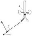
如图7所示,本发明的另一个实施例提供一种下腔静脉滤器输送装置,其包括上述的可调弯鞘管2、滤器1和滤器释放单元3;所述滤器释放单元 3携带所述滤器2从所述可调弯鞘管1的管腔沿从近端到远端的方向送入体内并释放。As shown in FIG. 7 , another embodiment of the present invention provides an inferior vena cava filter delivery device, which includes the above-mentioned
所述可调弯鞘管,包括鞘管管体、调节丝和调节器,其中,The adjustable bendable sheath includes a sheath body, an adjustment wire and an adjuster, wherein,
所述鞘管管体为柔性材料,其进入体内后在导丝的作用下可随血管走向弯曲;所述鞘管管体的近端外露于体外且与所述调节器固定连接;The sheath tube body is a flexible material, which can be bent along the direction of the blood vessel under the action of the guide wire after entering the body; the proximal end of the sheath tube body is exposed outside the body and is fixedly connected with the regulator;
所述鞘管管体的管壁夹层内设有沿其长度方向贯通的通道,所述调节丝从所述通道的近端穿入,到达所述通道的远端并与设置在所述鞘管管体远端的固定段固定,所述调节丝沿所述固定段的长度与之整段固定,所述固定段在自然状态下呈直线状态;The tube wall interlayer of the sheath tube body is provided with a channel passing through along its length direction, the adjustment wire penetrates from the proximal end of the channel, reaches the distal end of the channel, and is connected with the sheath tube. The fixed section at the distal end of the tube body is fixed, the adjustment wire is fixed to the entire section along the length of the fixed section, and the fixed section is in a straight state in a natural state;
所述调节丝的近端与所述调节器的调节单元连接,所述调节丝在所述调节单元的拉动下使所述固定段整体偏斜一个角度。The proximal end of the adjustment wire is connected with the adjustment unit of the adjuster, and the adjustment wire makes the entire fixed section deflect an angle under the pulling of the adjustment unit.
在一优选实施例中,所述滤器1还可以包括回收钩4,所述回收钩4设置在所述滤器1的尾端。所述滤器1的尾端朝向远端方向。当滤器1在体内放置一段时间后,通过回收钩4即可回收该过滤器。所述回收钩4可以为图 7所示的环形,也可以为弯钩状。In a preferred embodiment, the filter 1 may further include a
本发明的技术方案通过在所述鞘管管体的管壁夹层内设置沿其长度方向贯通的通道,使所述调节丝从所述通道的近端穿入,到达所述通道的远端并与设置在所述鞘管管体远端的固定段固定,所述调节丝沿所述固定段的长度与之整段固定,由于所述固定段是一段直线段,不同于一个点,因此所述调节丝与整个所述固定段固定时,会使所述固定段在自然状态下仍然呈直线状态,同时由于所述调节丝的近端与所述调节器的调节单元连接,因此所述调节丝在所述调节单元的拉动下能够使所述固定段整体与其它与之相连的鞘管部分偏斜一个角度,因此可以实现所述鞘管管体在左、右髂静脉汇合处上行折弯后到达下腔静脉进行静脉滤器释放时处于与腔静脉长轴平行的状态,从而保证了滤器被释放后能够沿正确的方向放置,使腔静脉滤器释放时获得最佳的固定位置。The technical solution of the present invention is to provide a channel running through the length direction of the sheath tube body in the tube wall interlayer, so that the adjustment wire penetrates from the proximal end of the channel, reaches the distal end of the channel, and It is fixed with the fixed section arranged at the distal end of the sheath tube body, and the adjustment wire is fixed with the entire section along the length of the fixed section. Since the fixed section is a straight section, different from a point, the When the adjustment wire is fixed with the entire fixed section, the fixed section is still in a straight state in a natural state. At the same time, because the proximal end of the adjustment wire is connected with the adjustment unit of the Under the pulling of the adjusting unit, the wire can make the whole of the fixed section and other sheath parts connected to it deflect an angle, so the sheath tube body can be bent upward at the confluence of the left and right iliac veins. After reaching the inferior vena cava to release the vena cava filter, it is in a state parallel to the long axis of the vena cava, so as to ensure that the filter can be placed in the correct direction after being released, so that the vena cava filter can obtain the best fixed position when it is released.
虽然,上文中已经用一般性说明及具体实施方案对本发明作了详尽的描述,但在本发明基础上,可以对之作一些修改或改进,这对本领域技术人员而言是显而易见的。因此,在不偏离本发明精神的基础上所做的这些修改或改进,均属于本发明要求保护的范围。Although the present invention has been described in detail above with general description and specific embodiments, it is obvious to those skilled in the art that some modifications or improvements can be made on the basis of the present invention. Therefore, these modifications or improvements made without departing from the spirit of the present invention fall within the scope of the claimed protection of the present invention.
Claims (8)
Translated fromChinesePriority Applications (1)
| Application Number | Priority Date | Filing Date | Title |
|---|---|---|---|
| CN201910858389.6ACN110693628B (en) | 2019-09-11 | 2019-09-11 | Adjustable curved sheath tube and inferior vena cava filter delivery device |
Applications Claiming Priority (1)
| Application Number | Priority Date | Filing Date | Title |
|---|---|---|---|
| CN201910858389.6ACN110693628B (en) | 2019-09-11 | 2019-09-11 | Adjustable curved sheath tube and inferior vena cava filter delivery device |
Publications (2)
| Publication Number | Publication Date |
|---|---|
| CN110693628Atrue CN110693628A (en) | 2020-01-17 |
| CN110693628B CN110693628B (en) | 2025-01-10 |
Family
ID=69195530
Family Applications (1)
| Application Number | Title | Priority Date | Filing Date |
|---|---|---|---|
| CN201910858389.6AActiveCN110693628B (en) | 2019-09-11 | 2019-09-11 | Adjustable curved sheath tube and inferior vena cava filter delivery device |
Country Status (1)
| Country | Link |
|---|---|
| CN (1) | CN110693628B (en) |
Cited By (3)
| Publication number | Priority date | Publication date | Assignee | Title |
|---|---|---|---|---|
| CN111714252A (en)* | 2020-07-17 | 2020-09-29 | 上海翰凌医疗器械有限公司 | A valve delivery device |
| CN111991674A (en)* | 2020-09-26 | 2020-11-27 | 龙德勇 | Device and method for ablation of hypertrophic obstructive cardiomyopathy |
| CN112245767A (en)* | 2020-10-30 | 2021-01-22 | 广东脉搏医疗科技有限公司 | Controllable bent catheter |
Citations (16)
| Publication number | Priority date | Publication date | Assignee | Title |
|---|---|---|---|---|
| US6440077B1 (en)* | 1999-06-02 | 2002-08-27 | Matthew T. Jung | Apparatus and method for the intravascular ultrasound-guided placement of a vena cava filter |
| US20080243222A1 (en)* | 2007-04-02 | 2008-10-02 | Cook Incorporated | High flex introducer assembly |
| JP4224123B1 (en)* | 2008-05-20 | 2009-02-12 | 日本ライフライン株式会社 | Catheter handle |
| CN102580225A (en)* | 2012-02-10 | 2012-07-18 | 先健科技(深圳)有限公司 | adjustable curved sheath |
| CN203663213U (en)* | 2013-12-27 | 2014-06-25 | 先健科技(深圳)有限公司 | Sheath capable of being bent |
| CN103877660A (en)* | 2012-02-10 | 2014-06-25 | 先健科技(深圳)有限公司 | Adjustable bent sheath |
| CN105251094A (en)* | 2015-09-22 | 2016-01-20 | 先健科技(深圳)有限公司 | Bendable sheathing canal |
| CN205181963U (en)* | 2015-09-22 | 2016-04-27 | 先健科技(深圳)有限公司 | Adjustable bent sheath |
| CN205759106U (en)* | 2016-04-13 | 2016-12-07 | 上海形状记忆合金材料有限公司 | A kind of sheath pipe changing camber and pliability |
| WO2019019937A1 (en)* | 2017-07-27 | 2019-01-31 | 先健科技(深圳)有限公司 | Adjustable curved sheath and medical instrument |
| CN208741206U (en)* | 2017-08-30 | 2019-04-16 | 科塞尔医疗科技(苏州)有限公司 | A kind of transportation system of vena cava filter |
| CN208851537U (en)* | 2018-03-16 | 2019-05-14 | 上海形状记忆合金材料有限公司 | An adjustable bendable delivery sheath capable of displaying the bending angle |
| CN109771087A (en)* | 2017-11-10 | 2019-05-21 | 上海微创心脉医疗科技股份有限公司 | A kind of recyclable device |
| CN209019057U (en)* | 2017-11-10 | 2019-06-25 | 上海微创心脉医疗科技股份有限公司 | A kind of recyclable device |
| CN109984823A (en)* | 2018-01-03 | 2019-07-09 | 杭州启明医疗器械股份有限公司 | It is a kind of to adjust curved sheath and the transportation system using the curved sheath of the tune |
| CN211325884U (en)* | 2019-09-11 | 2020-08-25 | 中国医学科学院北京协和医院 | An adjustable sheath tube and inferior vena cava filter delivery device |
- 2019
- 2019-09-11CNCN201910858389.6Apatent/CN110693628B/enactiveActive
Patent Citations (16)
| Publication number | Priority date | Publication date | Assignee | Title |
|---|---|---|---|---|
| US6440077B1 (en)* | 1999-06-02 | 2002-08-27 | Matthew T. Jung | Apparatus and method for the intravascular ultrasound-guided placement of a vena cava filter |
| US20080243222A1 (en)* | 2007-04-02 | 2008-10-02 | Cook Incorporated | High flex introducer assembly |
| JP4224123B1 (en)* | 2008-05-20 | 2009-02-12 | 日本ライフライン株式会社 | Catheter handle |
| CN102580225A (en)* | 2012-02-10 | 2012-07-18 | 先健科技(深圳)有限公司 | adjustable curved sheath |
| CN103877660A (en)* | 2012-02-10 | 2014-06-25 | 先健科技(深圳)有限公司 | Adjustable bent sheath |
| CN203663213U (en)* | 2013-12-27 | 2014-06-25 | 先健科技(深圳)有限公司 | Sheath capable of being bent |
| CN105251094A (en)* | 2015-09-22 | 2016-01-20 | 先健科技(深圳)有限公司 | Bendable sheathing canal |
| CN205181963U (en)* | 2015-09-22 | 2016-04-27 | 先健科技(深圳)有限公司 | Adjustable bent sheath |
| CN205759106U (en)* | 2016-04-13 | 2016-12-07 | 上海形状记忆合金材料有限公司 | A kind of sheath pipe changing camber and pliability |
| WO2019019937A1 (en)* | 2017-07-27 | 2019-01-31 | 先健科技(深圳)有限公司 | Adjustable curved sheath and medical instrument |
| CN208741206U (en)* | 2017-08-30 | 2019-04-16 | 科塞尔医疗科技(苏州)有限公司 | A kind of transportation system of vena cava filter |
| CN109771087A (en)* | 2017-11-10 | 2019-05-21 | 上海微创心脉医疗科技股份有限公司 | A kind of recyclable device |
| CN209019057U (en)* | 2017-11-10 | 2019-06-25 | 上海微创心脉医疗科技股份有限公司 | A kind of recyclable device |
| CN109984823A (en)* | 2018-01-03 | 2019-07-09 | 杭州启明医疗器械股份有限公司 | It is a kind of to adjust curved sheath and the transportation system using the curved sheath of the tune |
| CN208851537U (en)* | 2018-03-16 | 2019-05-14 | 上海形状记忆合金材料有限公司 | An adjustable bendable delivery sheath capable of displaying the bending angle |
| CN211325884U (en)* | 2019-09-11 | 2020-08-25 | 中国医学科学院北京协和医院 | An adjustable sheath tube and inferior vena cava filter delivery device |
Cited By (4)
| Publication number | Priority date | Publication date | Assignee | Title |
|---|---|---|---|---|
| CN111714252A (en)* | 2020-07-17 | 2020-09-29 | 上海翰凌医疗器械有限公司 | A valve delivery device |
| CN111991674A (en)* | 2020-09-26 | 2020-11-27 | 龙德勇 | Device and method for ablation of hypertrophic obstructive cardiomyopathy |
| CN111991674B (en)* | 2020-09-26 | 2024-03-26 | 龙德勇 | Ablation device and method for fat-thickness obstructive cardiomyopathy |
| CN112245767A (en)* | 2020-10-30 | 2021-01-22 | 广东脉搏医疗科技有限公司 | Controllable bent catheter |
Also Published As
| Publication number | Publication date |
|---|---|
| CN110693628B (en) | 2025-01-10 |
Similar Documents
| Publication | Publication Date | Title |
|---|---|---|
| AU2019264552B2 (en) | Percutaneous system, devices and methods | |
| NL192372C (en) | Device for carrying out intravenous therapy and hyperalimentation. | |
| US12011551B2 (en) | Fenestration devices, systems, and methods | |
| CN110693628A (en) | An adjustable sheath tube and inferior vena cava filter delivery device | |
| US5306262A (en) | Coronary catheter | |
| US20070287967A1 (en) | Selective renal cannulation and infusion systems and methods | |
| US20190015232A1 (en) | Transcatheter insertion system | |
| EP0154403A1 (en) | Loop coronary catheter | |
| CN104640583B (en) | blocked access system | |
| GB2200848A (en) | Intravenous filter, and apparatus and method for pre-operative preparation thereof | |
| JP2020142071A (en) | Sensor devices and operating methods for catheter treatment of myocardial microangiopathy | |
| CN211325884U (en) | An adjustable sheath tube and inferior vena cava filter delivery device | |
| US20170189063A1 (en) | Transcatheter insertion method | |
| CN112244961A (en) | Sheath pipe adjusting mechanism and adjustable bent sheath pipe | |
| CN213606754U (en) | Sheath pipe adjusting mechanism and adjustable bent sheath pipe | |
| WO2000029056A2 (en) | Coronary infusion catheter and intra-coronary drug administration methods | |
| CN116585067B (en) | Vascular sheath for preventing blood flow from blocking | |
| CN221243705U (en) | Segmentation adjustable curved sheath pipe | |
| Longatti et al. | The marionette technique for treatment of isolated fourth ventricle | |
| WO2025107297A1 (en) | Balloon dilatation catheter and vascular intervention system | |
| CN118576865A (en) | A bending-adjusting microcatheter with a detachable handle and an operation method thereof |
Legal Events
| Date | Code | Title | Description |
|---|---|---|---|
| PB01 | Publication | ||
| PB01 | Publication | ||
| SE01 | Entry into force of request for substantive examination | ||
| SE01 | Entry into force of request for substantive examination | ||
| GR01 | Patent grant | ||
| GR01 | Patent grant |