CN110693551A - Dura mater suture pusher for simulating nerve endoscopic skull base operation - Google Patents
Dura mater suture pusher for simulating nerve endoscopic skull base operationDownload PDFInfo
- Publication number
- CN110693551A CN110693551ACN201910939347.5ACN201910939347ACN110693551ACN 110693551 ACN110693551 ACN 110693551ACN 201910939347 ACN201910939347 ACN 201910939347ACN 110693551 ACN110693551 ACN 110693551A
- Authority
- CN
- China
- Prior art keywords
- movable
- column
- plate
- casing
- simulating
- Prior art date
- Legal status (The legal status is an assumption and is not a legal conclusion. Google has not performed a legal analysis and makes no representation as to the accuracy of the status listed.)
- Granted
Links
- 210000001154skull baseAnatomy0.000titleclaimsabstractdescription24
- 210000001951dura materAnatomy0.000titledescription2
- 210000005036nerveAnatomy0.000title1
- 238000001356surgical procedureMethods0.000claimsabstractdescription25
- 230000000903blocking effectEffects0.000claimsdescription18
- 238000001125extrusionMethods0.000claimsdescription5
- 239000013013elastic materialSubstances0.000claimsdescription3
- 239000002184metalSubstances0.000claimsdescription3
- 238000010586diagramMethods0.000description5
- 238000000034methodMethods0.000description4
- 238000007428craniotomyMethods0.000description2
- 230000000694effectsEffects0.000description2
- 238000002674endoscopic surgeryMethods0.000description2
- 230000003902lesionEffects0.000description2
- 238000004088simulationMethods0.000description2
- 206010051290Central nervous system lesionDiseases0.000description1
- 206010008164Cerebrospinal fluid leakageDiseases0.000description1
- 208000007913Pituitary NeoplasmsDiseases0.000description1
- 201000005746Pituitary adenomaDiseases0.000description1
- 206010061538Pituitary tumour benignDiseases0.000description1
- 230000009286beneficial effectEffects0.000description1
- 210000005013brain tissueAnatomy0.000description1
- 230000001815facial effectEffects0.000description1
- 208000015181infectious diseaseDiseases0.000description1
- 238000007917intracranial administrationMethods0.000description1
- 238000002406microsurgeryMethods0.000description1
- 208000021310pituitary gland adenomaDiseases0.000description1
- 230000002980postoperative effectEffects0.000description1
- 238000011084recoveryMethods0.000description1
- 210000003813thumbAnatomy0.000description1
Images


Classifications
- A—HUMAN NECESSITIES
- A61—MEDICAL OR VETERINARY SCIENCE; HYGIENE
- A61B—DIAGNOSIS; SURGERY; IDENTIFICATION
- A61B17/00—Surgical instruments, devices or methods
- A61B17/04—Surgical instruments, devices or methods for suturing wounds; Holders or packages for needles or suture materials
- A61B17/0469—Suturing instruments for use in minimally invasive surgery, e.g. endoscopic surgery
- G—PHYSICS
- G09—EDUCATION; CRYPTOGRAPHY; DISPLAY; ADVERTISING; SEALS
- G09B—EDUCATIONAL OR DEMONSTRATION APPLIANCES; APPLIANCES FOR TEACHING, OR COMMUNICATING WITH, THE BLIND, DEAF OR MUTE; MODELS; PLANETARIA; GLOBES; MAPS; DIAGRAMS
- G09B23/00—Models for scientific, medical, or mathematical purposes, e.g. full-sized devices for demonstration purposes
- G09B23/28—Models for scientific, medical, or mathematical purposes, e.g. full-sized devices for demonstration purposes for medicine
- A—HUMAN NECESSITIES
- A61—MEDICAL OR VETERINARY SCIENCE; HYGIENE
- A61B—DIAGNOSIS; SURGERY; IDENTIFICATION
- A61B17/00—Surgical instruments, devices or methods
- A61B17/04—Surgical instruments, devices or methods for suturing wounds; Holders or packages for needles or suture materials
- A61B17/0469—Suturing instruments for use in minimally invasive surgery, e.g. endoscopic surgery
- A61B2017/0474—Knot pushers
Landscapes
- Engineering & Computer Science (AREA)
- Health & Medical Sciences (AREA)
- General Health & Medical Sciences (AREA)
- General Physics & Mathematics (AREA)
- Surgery (AREA)
- Life Sciences & Earth Sciences (AREA)
- Physics & Mathematics (AREA)
- Medical Informatics (AREA)
- Medicinal Chemistry (AREA)
- Computational Mathematics (AREA)
- Molecular Biology (AREA)
- Public Health (AREA)
- Veterinary Medicine (AREA)
- Chemical & Material Sciences (AREA)
- Heart & Thoracic Surgery (AREA)
- Biomedical Technology (AREA)
- Algebra (AREA)
- Animal Behavior & Ethology (AREA)
- Nuclear Medicine, Radiotherapy & Molecular Imaging (AREA)
- Mathematical Analysis (AREA)
- Mathematical Optimization (AREA)
- Mathematical Physics (AREA)
- Pure & Applied Mathematics (AREA)
- Business, Economics & Management (AREA)
- Educational Administration (AREA)
- Educational Technology (AREA)
- Theoretical Computer Science (AREA)
- Surgical Instruments (AREA)
Abstract
Translated fromChineseDescription
Translated fromChinese技术领域technical field
本发明涉及医疗领域,具体来说,涉及一种用于模拟神经内镜颅底手术硬膜缝合推线器。The invention relates to the medical field, in particular to a dural suture thread pusher for simulating neuroendoscopic skull base surgery.
背景技术Background technique
目前,随着神经内镜手术技术的发展,越来越多的先前需要开颅在显微镜下完成的腹侧颅底病变和脑深部病变能够通过神经内镜手术切除。比如,约95%的垂体腺瘤手术能通过经鼻内镜手术完成。全内镜下颅底外科的概念被越来越多的神经外科医生接受。神经内镜手术与开颅显微手术相比具有近距离观察病变、经鼻完成对脑组织骚扰轻、广角视野、无颜面部切口、术后康复快、住院时间短等诸多优点。但该术式亦有其自身的局限性。内镜手术后术区深在,缝合硬脑膜困难,围手术期容易发生脑脊液漏和颅内感染,在某种程度上影响了神经内镜颅底手术的推广。由于内镜本身占据一定空间,术腔较深,留给其他手术器械的操作空间较小,器械移动自由度受限难以完成深部打结操作,特别是缝线成结后如何将线结推向指定缝合部位是神经内镜颅底手术中颅底重建过程的难点之一,因此,增加手术医生的模拟操作训练提高手术技巧是解决这一难题的最佳方案。At present, with the development of neuroendoscopic surgical techniques, more and more lesions of the ventral skull base and deep brain lesions that previously required craniotomy to be completed under the microscope can be resected by neuroendoscopic surgery. For example, about 95% of pituitary adenoma surgery can be done by transnasal endoscopic surgery. The concept of total endoscopic skull base surgery is increasingly accepted by neurosurgeons. Compared with craniotomy microsurgery, neuroendoscopic surgery has many advantages, such as close observation of lesions, less harassment of brain tissue, wide-angle field of view, no facial incision, faster postoperative recovery, and shorter hospital stay. But this technique also has its own limitations. After endoscopic surgery, the operative area is deep, it is difficult to suture the dura mater, and cerebrospinal fluid leakage and intracranial infection are prone to occur during the perioperative period, which affects the promotion of neuroendoscopic skull base surgery to some extent. Since the endoscope itself occupies a certain space and the surgical cavity is deep, there is less room for other surgical instruments to operate, and the freedom of movement of the instruments is limited, and it is difficult to complete the deep knotting operation, especially how to push the knot to the suture after the knot is formed. Specifying the suture site is one of the difficulties in the process of skull base reconstruction in neuroendoscopic skull base surgery. Therefore, increasing the surgeon's simulated operation training to improve surgical skills is the best solution to this problem.
发明内容SUMMARY OF THE INVENTION
本发明的技术任务是针对以上不足,提供一种用于模拟神经内镜颅底手术硬膜缝合推线器,来增加手术医生的模拟操作训练的提高。The technical task of the present invention is to provide a dural suture thread pusher for simulating neuroendoscopic skull base surgery to improve the simulation operation training of surgeons in view of the above shortcomings.
本发明的技术方案是这样实现的:The technical scheme of the present invention is realized as follows:
一种用于模拟神经内镜颅底手术硬膜缝合推线器,包括壳体,所述壳体的上端设有固定块,所述壳体的上端穿插设有活动柱一,所述壳体的下端穿插设有活动柱二,所述活动柱一的上端设有限位块,所述活动柱二的下端设有推线块,所述活动柱二与所述壳体之间通过活动套连接。A dural suture thread pusher for simulating neuroendoscopic skull base surgery, comprising a casing, the upper end of the casing is provided with a fixing block, and the upper end of the casing is interspersed with a movable column. The lower end of the movable column is interspersed with a second movable column, the upper end of the
优选的,所述壳体的两侧下端均设有固定装置,所述固定装置的上方且所述壳体的两侧均设有挂钩,所述挂钩的上方且位于所述壳体的一侧开设有开口,其中,所述固定装置包括固定板一及固定板二,并且,所述固定板一的一侧与所述壳体连接,所述固定板一与所述固定板二之间开设有放置槽,所述固定板一的一端两侧均设有活动板一,所述固定板一的另一端两侧均设有活动板二,并且,所述活动板一与所述活动板二远离所述固定板一的一端均与活动杆连接,所述活动板一与所述固定板二之间通过活动轴一连接,所述活动杆的远离所述活动板一的一端设有连接块,所述连接块的一侧设有与所述挂钩相配合的拉绳,所述活动柱一与所述活动柱二之间且位于所述壳体的内部设有伸缩装置,其中,所述伸缩装置包括挤压片,并且,所述挤压片的一侧与所述活动柱二的一端连接,所述挤压片的另一侧与所述活动柱一的一端连接,所述活动柱二靠近所述挤压片的一端设有限位柱,所述限位柱的一侧设有限位片,所述活动套与所述活动柱一之间且位于所述壳体的内部设有连接杆,所述活动柱一靠近所述挤压片的一端设有挡块,所述活动柱一上且位于所述挡块与所述固定块之间套设有弹簧;所述挂钩呈L形结构,并且,所述拉绳为弹性材质制成。Preferably, fixing devices are provided at the lower ends of both sides of the housing, hooks are provided above the fixing devices and on both sides of the housing, and the hooks are located above and on one side of the housing An opening is provided, wherein the fixing device includes a
优选的,所述放置槽的内部两侧均设有若干锯齿。Preferably, a plurality of saw teeth are provided on both sides of the inside of the placement groove.
优选的,所述活动板一及所述活动板二与所述固定板一之间均通过活动轴二连接。Preferably, the
优选的,所述活动板一及所述活动板二与所述活动杆之间均通过活动轴三连接。Preferably, the first movable plate, the second movable plate and the movable rod are connected by the third movable shaft.
优选的,所述推线块呈半球形结构,并且,所述推线块的上端中间位置设有夹槽。Preferably, the push wire block has a hemispherical structure, and a clamping groove is provided in the middle position of the upper end of the push wire block.
优选的,所述挤压片包括挡片一、连接柱及挡片二,所述连接柱的两端分别与所述挡片一及所述挡片二连接,所述挡片一的下端设有与所述限位柱相配合的卡槽。Preferably, the extrusion sheet includes a
优选的,所述挡片一、所述连接柱及所述挡片二均为金属弹片。Preferably, the first blocking piece, the connecting column and the second blocking piece are all metal elastic pieces.
优选的,所述连接柱的一端呈L形结构,与所述开口相互配合。Preferably, one end of the connecting column is in an L-shaped structure, which cooperates with the opening.
优选的,所述活动柱一的一侧设有导向条,所述固定块的内侧设有导向槽,且所述导向条与所述导向槽滑动相连。Preferably, one side of the
本发明的有益效果:Beneficial effects of the present invention:
1、通过壳体内的伸缩装置带动推线块运动,使得推线块将缝线成结后的线结推向指定的缝合部位,通过弹簧的弹力作用,受训人员将缝线成结后的线结推向指定的缝合部位后,再进行位置固定;1. The pusher block is driven by the telescopic device in the casing, so that the pusher block pushes the knotted suture to the designated suture part, and the trainee will stitch the suture into the knotted thread by the elastic force of the spring. After the knot is pushed to the designated suture site, the position is fixed;
2、本发明的模拟神经内镜颅底手术硬膜缝合推线器,结构简单,功能强大,操作方便,使用该装置确保了缝合效果,通过导向条和导向槽滑动相连的作用,防止活动柱一沿着活动套方向移动时不会出现旋转现象的发生,确保了活动柱一移动的稳定性,通过此模拟装置,提高了手术医生的手术技巧。2. The dural suture thread pusher for simulating neuroendoscopic skull base surgery of the present invention has a simple structure, powerful functions and convenient operation. The use of the device ensures the suture effect. The sliding connection between the guide strip and the guide groove prevents the movable column When moving along the direction of the movable sleeve, there is no rotation phenomenon, which ensures the stability of the movable column when moving, and improves the surgical skills of the surgeon through the simulation device.
附图说明Description of drawings
为了更清楚地说明本发明实施例或现有技术中的技术方案,下面将对实施例中所需要使用的附图作简单地介绍,显而易见地,下面描述中的附图仅仅是本发明的一些实施例,对于本领域普通技术人员来讲,在不付出创造性劳动的前提下,还可以根据这些附图获得其他的附图。In order to more clearly illustrate the embodiments of the present invention or the technical solutions in the prior art, the accompanying drawings required in the embodiments will be briefly introduced below. Obviously, the drawings in the following description are only some of the present invention. In the embodiments, for those of ordinary skill in the art, other drawings can also be obtained according to these drawings without any creative effort.
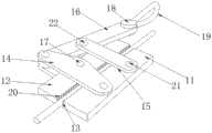
图1是根据本发明实施例的一种用于模拟神经内镜颅底手术硬膜缝合推线器的结构示意图;1 is a schematic structural diagram of a dural suture pusher for simulating neuroendoscopic skull base surgery according to an embodiment of the present invention;
图2是根据本发明实施例的固定装置的结构示意图;2 is a schematic structural diagram of a fixing device according to an embodiment of the present invention;
图3是根据本发明实施例的伸缩装置的结构示意图;3 is a schematic structural diagram of a telescopic device according to an embodiment of the present invention;
图4是根据本发明实施例的挤压片的结构示意图;4 is a schematic structural diagram of an extruded sheet according to an embodiment of the present invention;
图5是根据本发明实施例的推线块的结构示意图。FIG. 5 is a schematic structural diagram of a push wire block according to an embodiment of the present invention.
图中:In the picture:
1、壳体;2、固定块;3、活动柱一;4、活动柱二;5、限位块;6、推线块;7、活动套;8、固定装置;9、挂钩;10、开口;11、固定板一;12、固定板二;13、放置槽;14、活动板一;15、活动板二;16、活动杆;17、活动轴一;18、连接块;19、拉绳;20、锯齿;21、活动轴二;22、活动轴三;23、挤压片;24、限位柱; 25、限位片;26、连接杆;27、挡块;28、弹簧;29、挡片一;30、连接柱;31、挡片二;32、卡槽;33、导向条;34、导向槽。1. Shell; 2. Fixed block; 3. Active column one; 4. Active column two; 5. Limit block; 6. Push line block; 7. Active sleeve; 8. Fixed device; 9. Hook; Opening; 11. Fixed plate one; 12. Fixed plate two; 13. Placement slot; 14. Active plate one; 15. Active plate two; 16. Active rod; rope; 20, sawtooth; 21, active shaft two; 22, active shaft three; 23, extrusion piece; 24, limit post; 25, limit piece; 26, connecting rod; 27, stop; 28, spring; 29.
具体实施方式Detailed ways
在本发明的描述中,需要理解的是,术与″中心″、″横向″、″上″、″下″、″左″、″右″、″竖直″、″水平″、″顶″、″底″、″内″、″外″等指示的方位或位置关系为基于附图所示的方位或位置关系,仅是为了便于描述本发明和简化描述,而不是指示或暗示所指的装置或元件必须具有特定的方位、以特定的方位构造和操作,因此不能理解为对本发明的限制。此外,术与″第一″、″第二″仅用于描述目的,而不能理解为指示或暗示相对重要性或者隐含指明所指示的技术特征的数量。由此,限定有″第一″、″第二″的特征可以明示或者隐含地包括一个或者更多个该特征。在本发明的描述中,除非另有说明,″多个″的含义是两个或两个以上。另外,术与″包括″及其任何变形,意图在于覆盖不排他的包含。In the description of the present invention, it should be understood that "center", "horizontal", "top", "bottom", "left", "right", "vertical", "horizontal", "top" The orientation or positional relationship indicated by , "bottom", "inside", "outside", etc. are based on the orientation or positional relationship shown in the accompanying drawings, which are only for the convenience of describing the present invention and simplifying the description, rather than indicating or implying that A device or element must have a particular orientation, be constructed and operate in a particular orientation, and therefore should not be construed as limiting the invention. In addition, the terms "first" and "second" are only used for descriptive purposes, and should not be understood as indicating or implying relative importance or implying the number of indicated technical features. Thus, a feature defined as "first", "second" may expressly or implicitly include one or more of that feature. In the description of the present invention, unless otherwise specified, "plurality" means two or more. Additionally, the term "comprising" and any variations thereof are intended to cover non-exclusive inclusion.
下面结合附图和具体实施例对本发明作进一步说明。The present invention will be further described below with reference to the accompanying drawings and specific embodiments.
实施例一,如图1-4所示,根据本发明实施例的一种用于模拟神经内镜颅底手术硬膜缝合推线器,包括壳体1,对于壳体1的结构设计,一般采用柱形结构,且内部呈空心结构,壳体1的上端设有固定块2,壳体1的上端穿插设有活动柱一3,壳体1的下端穿插设有活动柱二4,这里需要注意的是,壳体1的两端均设有与活动柱一3及活动柱二4相配合的通孔,活动柱一3的上端设有限位块5,活动柱二4的下端设有推线块6,显然,推线块6呈半球形结构,并且,推线块6的上端中间位置设有夹槽35,活动柱二 4与壳体1之间通过活动套7连接,壳体1的两侧下端均设有固定装置8,固定装置8的上方且壳体1的两侧均设有挂钩9,挂钩 9呈L形结构,便于将拉绳19固定,挂钩9的上方且位于壳体1 的一侧开设有开口10。
下面具体介绍一下固定装置8的结构及作用。The structure and function of the fixing
如图2所示,固定装置8包括固定板一11及固定板二12,并且,固定板一11的一侧与壳体1连接,固定板一11与固定板二12之间开设有放置槽13,发明人为了将线头固定更加牢靠,在放置槽13的内部两侧均设有若干锯齿20,固定板一11的一端两侧均设有活动板一14,固定板一11的另一端两侧均设有活动板二15,活动板一14及活动板二15与固定板一11之间均通过活动轴二21连接,并且,活动板一14与活动板二15远离固定板一11的一端均与活动杆16连接,活动板一14及活动板二15 与活动杆16之间均通过活动轴三22连接,活动板一14与固定板二12之间通过活动轴一17连接,活动杆16的远离活动板一 14的一端设有连接块18,连接块18的一侧设有与挂钩9相配合的拉绳19,并且,拉绳19为弹性材质制成,活动柱一3与活动柱二4之间且位于壳体1的内部设有伸缩装置。As shown in FIG. 2 , the fixing
下面具体介绍一下伸缩装置的结构及作用。The structure and function of the expansion device are introduced in detail below.
如图3所示,伸缩装置包括挤压片23,并且,挤压片23的一侧与活动柱二4的一端连接,挤压片23的另一侧与活动柱一3 的一端连接,活动柱二4靠近挤压片23的一端设有限位柱24,限位柱24的一侧设有限位片25,活动套7与活动柱一3之间且位于壳体1的内部设有连接杆26,活动柱一3靠近挤压片23的一端设有挡块27,活动柱一3上且位于挡块27与固定块2之间套设有弹簧28,发明人为了防止活动柱一3沿着活动套7方向移动时出现旋转现象,在活动柱一3的一侧设有导向条33,固定块2 的内侧设有导向槽34,且导向条33与导向槽34滑动相连。As shown in FIG. 3, the telescopic device includes an extruding
如图4所示,挤压片23包括挡片一29、连接柱30及挡片二 31,连接柱30的两端分别与挡片一29及挡片二31连接,挡片一29的下端设有与限位柱24相配合的卡槽32,挡片一29、连接柱30及挡片二31均为金属弹片,连接柱30的一端呈L形结构,与开口10相互配合。As shown in FIG. 4 , the
为了方便理解本发明的上述技术方案,以下就本发明在实际过程中的工作原理或者操作方式进行详细说明In order to facilitate the understanding of the above technical solutions of the present invention, the working principle or operation mode of the present invention in the actual process will be described in detail below.
在实际应用时:首先受训医生将缝合部位的缝合线打结后线结的一端穿过壳体1左侧的放置槽13内,再将另一端穿过壳体1 右侧的放置槽13,此时,受训医生拉动拉绳19,将拉绳19挂到挂钩9上,进而拉绳19固定,因此,拉绳19带动连接块18运动,使得连接块18带动活动杆16运动,因为活动杆16与活动板一14及活动板二15通过活动轴三22连接,进而活动杆16的运动带动活动板一14及活动板二15运动,因为活动板一14与固定板二12之间通过活动轴一17连接,进而活动板一14带动固定板二12向上运动,进而放置槽13内的两侧锯齿20相互接触,将线结固定在放置槽13的内侧,此时,缝合线的线结处于推线块6的底部位置,通过夹槽35将线接卡住,受训医生再用大拇指按压挤压片23,使得挤压片23向壳体1内侧运动,当挤压片 23上的连接柱30与开口10分离时,连接柱30完全进入到壳体 1的内侧,此时,弹簧28处于展开状态,通过弹簧28产生弹力,使得活动柱一3带动弹簧28向活动柱二4的方向运动,进而弹簧 28带动挡块27挤压挡片二31,使得挡片二31挤压连接柱30及挡片一29,因为挡片一29与限位柱24通过卡槽32连接,进而挡片一29挤压活动柱二4使得活动柱二4向壳体1的外侧运动,此时,推线块6推动线结沿着缝合部位方向移动,通过导向条33 和导向槽34滑动相连的作用,防止活动柱一3沿着活动套7方向移动时不会出现旋转现象的发生,确保了活动柱一3移动的稳定性。In practical application: firstly, the trained doctor ties the suture at the suture, and then one end of the knot passes through the
综上所述,借助于本发明的上述技术方案,通过壳体1内的伸缩装置带动推线块6运动,使得推线块6将缝线成结后的线结推向患者的指定缝合部位,通过弹簧28的弹力作用,受训医生将缝线成结后的线结推向的指定缝合部位的状态进行位置固定;本发明的模拟神经内镜颅底手术硬膜缝合推线器,结构简单,功能强大,操作方便,使用该装置确保了缝合效果,通过导向条33和导向槽34滑动相连的作用,防止活动柱一3沿着活动套7方向移动时不会出现旋转现象的发生,确保了活动柱一3移动的稳定性。To sum up, with the help of the above technical solutions of the present invention, the
通过上面具体实施方式,所述技术领域的技术人员可容易的实现本发明。但是应当理解,本发明并不限于上述的具体实施方式。在公开的实施方式的基础上,所述技术领域的技术人员可任意组合不同的技术特征,从而实现不同的技术方案。Through the above specific embodiments, those skilled in the art can easily implement the present invention. However, it should be understood that the present invention is not limited to the specific embodiments described above. On the basis of the disclosed embodiments, those skilled in the technical field can arbitrarily combine different technical features to realize different technical solutions.
Claims (10)
Translated fromChinesePriority Applications (1)
| Application Number | Priority Date | Filing Date | Title |
|---|---|---|---|
| CN201910939347.5ACN110693551B (en) | 2019-09-29 | 2019-09-29 | Dura mater suture pusher for simulating nerve endoscopic skull base operation |
Applications Claiming Priority (1)
| Application Number | Priority Date | Filing Date | Title |
|---|---|---|---|
| CN201910939347.5ACN110693551B (en) | 2019-09-29 | 2019-09-29 | Dura mater suture pusher for simulating nerve endoscopic skull base operation |
Publications (2)
| Publication Number | Publication Date |
|---|---|
| CN110693551Atrue CN110693551A (en) | 2020-01-17 |
| CN110693551B CN110693551B (en) | 2020-07-31 |
Family
ID=69197478
Family Applications (1)
| Application Number | Title | Priority Date | Filing Date |
|---|---|---|---|
| CN201910939347.5AActiveCN110693551B (en) | 2019-09-29 | 2019-09-29 | Dura mater suture pusher for simulating nerve endoscopic skull base operation |
Country Status (1)
| Country | Link |
|---|---|
| CN (1) | CN110693551B (en) |
Cited By (1)
| Publication number | Priority date | Publication date | Assignee | Title |
|---|---|---|---|---|
| CN112754556A (en)* | 2021-01-18 | 2021-05-07 | 吉林大学第一医院 | Skull base wound dura mater suture device |
Citations (8)
| Publication number | Priority date | Publication date | Assignee | Title |
|---|---|---|---|---|
| US5769863A (en)* | 1994-08-10 | 1998-06-23 | Heartport, Inc. | Surgical knot pusher and method of use |
| KR101222236B1 (en)* | 2010-12-01 | 2013-01-15 | 신현철 | Suture device for disk surgical operation |
| US9198678B2 (en)* | 2013-03-15 | 2015-12-01 | George Frey | Patient-matched apparatus and methods for performing surgical procedures |
| CN106137373A (en)* | 2016-08-04 | 2016-11-23 | 湖南坤昇三维科技有限公司 | Combination type spinal column puts nail guide plate and preparation method thereof |
| US20170319197A1 (en)* | 2001-12-21 | 2017-11-09 | Abbott Laboratories | Suture trimmer |
| CN109223075A (en)* | 2018-08-30 | 2019-01-18 | 武汉唯柯医疗科技有限公司 | A kind of suture knot pusher |
| CN109223078A (en)* | 2018-11-12 | 2019-01-18 | 中国人民解放军第四军医大学 | The suture of nerve endoscope skull base surgery dura mater pushes away line device |
| CN208988995U (en)* | 2018-06-20 | 2019-06-18 | 姚飞 | Minimally Invasive Surgery pushes away line hooking device |
- 2019
- 2019-09-29CNCN201910939347.5Apatent/CN110693551B/enactiveActive
Patent Citations (8)
| Publication number | Priority date | Publication date | Assignee | Title |
|---|---|---|---|---|
| US5769863A (en)* | 1994-08-10 | 1998-06-23 | Heartport, Inc. | Surgical knot pusher and method of use |
| US20170319197A1 (en)* | 2001-12-21 | 2017-11-09 | Abbott Laboratories | Suture trimmer |
| KR101222236B1 (en)* | 2010-12-01 | 2013-01-15 | 신현철 | Suture device for disk surgical operation |
| US9198678B2 (en)* | 2013-03-15 | 2015-12-01 | George Frey | Patient-matched apparatus and methods for performing surgical procedures |
| CN106137373A (en)* | 2016-08-04 | 2016-11-23 | 湖南坤昇三维科技有限公司 | Combination type spinal column puts nail guide plate and preparation method thereof |
| CN208988995U (en)* | 2018-06-20 | 2019-06-18 | 姚飞 | Minimally Invasive Surgery pushes away line hooking device |
| CN109223075A (en)* | 2018-08-30 | 2019-01-18 | 武汉唯柯医疗科技有限公司 | A kind of suture knot pusher |
| CN109223078A (en)* | 2018-11-12 | 2019-01-18 | 中国人民解放军第四军医大学 | The suture of nerve endoscope skull base surgery dura mater pushes away line device |
Cited By (1)
| Publication number | Priority date | Publication date | Assignee | Title |
|---|---|---|---|---|
| CN112754556A (en)* | 2021-01-18 | 2021-05-07 | 吉林大学第一医院 | Skull base wound dura mater suture device |
Also Published As
| Publication number | Publication date |
|---|---|
| CN110693551B (en) | 2020-07-31 |
Similar Documents
| Publication | Publication Date | Title |
|---|---|---|
| JP3162161U (en) | Endoscopic surgery / inspection training organ placement device and pulsation device | |
| JP3177527U (en) | Endoscopic surgery / inspection training organ placement device | |
| CN104248457B (en) | An artificial chord device, threading element and kit | |
| CN106419972B (en) | Bendable minimally invasive instrument capable of adjusting clamping force | |
| JP2004532683A (en) | Collection device | |
| JP2017502714A (en) | Suture for laparoscopic port site closure device | |
| CN101243988B (en) | Automatic ligation device | |
| KR20180122845A (en) | Surgical instrument equipment appropriate for mini-invasive surgery | |
| CN110693551B (en) | Dura mater suture pusher for simulating nerve endoscopic skull base operation | |
| WO2015153646A1 (en) | Minimally invasive surgery tissue (mist) clip | |
| CN108938023A (en) | For suturing the suture guide device of hysteroscope puncture | |
| CN107510482A (en) | Disposable tissue retraction folder | |
| CN109223078B (en) | Dural suture pusher for neuroendoscopic skull base surgery | |
| CN208573778U (en) | Knotting device in a kind of laparoscope puncture incision | |
| CN105902286A (en) | Stapler type endoscope suturing instrument | |
| CN207768470U (en) | A kind of surgical forceps for abdominoscope of adjustable in length | |
| KR20170051394A (en) | Surgical Clip Applier | |
| CN116269589B (en) | Bendable and adjustable child laparoscope hernia soft needle | |
| CN109223077A (en) | Nerve endoscope skull base surgery dura mater stitching knotter | |
| CN209122325U (en) | Neuroendoscopic skull base surgery dural suture pusher | |
| CN100574710C (en) | forceps lacunar stapler | |
| CN209091483U (en) | Neuroendoscopic skull base surgery dural suture knotter | |
| CN212369012U (en) | Disposable tissue suspension device | |
| CN211187389U (en) | Minimally invasive fascia stitching instrument | |
| CN209984668U (en) | A minimally invasive intracranial hematoma remover under video |
Legal Events
| Date | Code | Title | Description |
|---|---|---|---|
| PB01 | Publication | ||
| PB01 | Publication | ||
| SE01 | Entry into force of request for substantive examination | ||
| SE01 | Entry into force of request for substantive examination | ||
| GR01 | Patent grant | ||
| GR01 | Patent grant |