CN110691941A - Light Diffusion Fibers for White Light Emitting - Google Patents
Light Diffusion Fibers for White Light EmittingDownload PDFInfo
- Publication number
- CN110691941A CN110691941ACN201880035489.2ACN201880035489ACN110691941ACN 110691941 ACN110691941 ACN 110691941ACN 201880035489 ACN201880035489 ACN 201880035489ACN 110691941 ACN110691941 ACN 110691941A
- Authority
- CN
- China
- Prior art keywords
- light
- chromaticity
- optical fiber
- diffusing optical
- phosphor layer
- Prior art date
- Legal status (The legal status is an assumption and is not a legal conclusion. Google has not performed a legal analysis and makes no representation as to the accuracy of the status listed.)
- Pending
Links
- 239000000835fiberSubstances0.000titleclaimsdescription206
- 238000009792diffusion processMethods0.000titleclaimsdescription34
- OAICVXFJPJFONN-UHFFFAOYSA-NPhosphorusChemical compound[P]OAICVXFJPJFONN-UHFFFAOYSA-N0.000claimsabstractdescription298
- 239000013307optical fiberSubstances0.000claimsabstractdescription145
- 238000005253claddingMethods0.000claimsabstractdescription100
- 239000011521glassSubstances0.000claimsabstractdescription41
- 230000002596correlated effectEffects0.000claimsabstractdescription34
- 239000000463materialSubstances0.000claimsdescription98
- 229920000642polymerPolymers0.000claimsdescription72
- 239000011159matrix materialSubstances0.000claimsdescription58
- 239000000203mixtureSubstances0.000claimsdescription55
- 230000032683agingEffects0.000claimsdescription42
- 238000005286illuminationMethods0.000claimsdescription42
- 238000012360testing methodMethods0.000claimsdescription41
- 238000000034methodMethods0.000claimsdescription35
- 230000008859changeEffects0.000claimsdescription28
- 230000003287optical effectEffects0.000claimsdescription28
- 239000000872bufferSubstances0.000claimsdescription27
- VYPSYNLAJGMNEJ-UHFFFAOYSA-NSilicium dioxideChemical compoundO=[Si]=OVYPSYNLAJGMNEJ-UHFFFAOYSA-N0.000claimsdescription22
- GWEVSGVZZGPLCZ-UHFFFAOYSA-NTitan oxideChemical compoundO=[Ti]=OGWEVSGVZZGPLCZ-UHFFFAOYSA-N0.000claimsdescription14
- -1PolytetrafluoroethylenePolymers0.000claimsdescription13
- 150000004767nitridesChemical class0.000claimsdescription13
- 230000001902propagating effectEffects0.000claimsdescription13
- 238000004519manufacturing processMethods0.000claimsdescription10
- 239000002105nanoparticleSubstances0.000claimsdescription10
- 239000002096quantum dotSubstances0.000claimsdescription10
- 239000004812Fluorinated ethylene propyleneSubstances0.000claimsdescription9
- 229920000840ethylene tetrafluoroethylene copolymerPolymers0.000claimsdescription9
- 239000005038ethylene vinyl acetateSubstances0.000claimsdescription9
- 229920009441perflouroethylene propylenePolymers0.000claimsdescription9
- 229920001343polytetrafluoroethylenePolymers0.000claimsdescription9
- 239000004810polytetrafluoroethyleneSubstances0.000claimsdescription9
- 239000000377silicon dioxideSubstances0.000claimsdescription8
- 230000003595spectral effectEffects0.000claimsdescription8
- MCMNRKCIXSYSNV-UHFFFAOYSA-NZirconium dioxideChemical compoundO=[Zr]=OMCMNRKCIXSYSNV-UHFFFAOYSA-N0.000claimsdescription6
- 229920011301perfluoro alkoxyl alkanePolymers0.000claimsdescription6
- 229920001296polysiloxanePolymers0.000claimsdescription6
- 239000004813Perfluoroalkoxy alkaneSubstances0.000claimsdescription5
- XOLBLPGZBRYERU-UHFFFAOYSA-Ntin dioxideChemical compoundO=[Sn]=OXOLBLPGZBRYERU-UHFFFAOYSA-N0.000claimsdescription5
- 229920001634CopolyesterPolymers0.000claimsdescription4
- QHSJIZLJUFMIFP-UHFFFAOYSA-Nethene;1,1,2,2-tetrafluoroetheneChemical groupC=C.FC(F)=C(F)FQHSJIZLJUFMIFP-UHFFFAOYSA-N0.000claimsdescription4
- HQQADJVZYDDRJT-UHFFFAOYSA-Nethene;prop-1-eneChemical groupC=C.CC=CHQQADJVZYDDRJT-UHFFFAOYSA-N0.000claimsdescription4
- 239000004417polycarbonateSubstances0.000claimsdescription4
- 229920000515polycarbonatePolymers0.000claimsdescription4
- PNEYBMLMFCGWSK-UHFFFAOYSA-Naluminium oxideInorganic materials[O-2].[O-2].[O-2].[Al+3].[Al+3]PNEYBMLMFCGWSK-UHFFFAOYSA-N0.000claimsdescription3
- CETPSERCERDGAM-UHFFFAOYSA-Nceric oxideChemical compoundO=[Ce]=OCETPSERCERDGAM-UHFFFAOYSA-N0.000claimsdescription3
- 229910000422cerium(IV) oxideInorganic materials0.000claimsdescription3
- 229910052906cristobaliteInorganic materials0.000claimsdescription3
- BKQMNPVDJIHLPD-UHFFFAOYSA-NOS(=O)(=O)[Se]S(O)(=O)=OChemical classOS(=O)(=O)[Se]S(O)(=O)=OBKQMNPVDJIHLPD-UHFFFAOYSA-N0.000claims4
- 229910052605nesosilicateInorganic materials0.000claims4
- 150000004762orthosilicatesChemical class0.000claims4
- ADCOVFLJGNWWNZ-UHFFFAOYSA-Nantimony trioxideInorganic materialsO=[Sb]O[Sb]=OADCOVFLJGNWWNZ-UHFFFAOYSA-N0.000claims2
- 229910052681coesiteInorganic materials0.000claims2
- 229910052593corundumInorganic materials0.000claims2
- 229910052682stishoviteInorganic materials0.000claims2
- 229910052905tridymiteInorganic materials0.000claims2
- 229910001845yogo sapphireInorganic materials0.000claims2
- 239000010410layerSubstances0.000description269
- 238000000576coating methodMethods0.000description21
- 239000002245particleSubstances0.000description19
- 239000011248coating agentSubstances0.000description17
- 230000005540biological transmissionEffects0.000description11
- 230000015556catabolic processEffects0.000description11
- 238000006731degradation reactionMethods0.000description11
- 229920000915polyvinyl chloridePolymers0.000description11
- 239000004800polyvinyl chlorideSubstances0.000description11
- 239000011148porous materialSubstances0.000description10
- 238000010521absorption reactionMethods0.000description8
- 239000002019doping agentSubstances0.000description8
- BPQQTUXANYXVAA-UHFFFAOYSA-NOrthosilicateChemical compound[O-][Si]([O-])([O-])[O-]BPQQTUXANYXVAA-UHFFFAOYSA-N0.000description6
- 230000008878couplingEffects0.000description6
- 238000010168coupling processMethods0.000description6
- 238000005859coupling reactionMethods0.000description6
- 239000007787solidSubstances0.000description6
- 229920001169thermoplasticPolymers0.000description6
- DQXBYHZEEUGOBF-UHFFFAOYSA-Nbut-3-enoic acid;etheneChemical compoundC=C.OC(=O)CC=CDQXBYHZEEUGOBF-UHFFFAOYSA-N0.000description5
- 230000005670electromagnetic radiationEffects0.000description5
- 239000007788liquidSubstances0.000description5
- 229920001200poly(ethylene-vinyl acetate)Polymers0.000description5
- 235000012239silicon dioxideNutrition0.000description5
- 238000001228spectrumMethods0.000description5
- 238000000149argon plasma sinteringMethods0.000description4
- 230000007547defectEffects0.000description4
- 238000009826distributionMethods0.000description4
- 238000005259measurementMethods0.000description4
- 239000011295pitchSubstances0.000description4
- 229920002725thermoplastic elastomerPolymers0.000description4
- 229920002803thermoplastic polyurethanePolymers0.000description4
- 239000004408titanium dioxideSubstances0.000description4
- NIXOWILDQLNWCW-UHFFFAOYSA-MAcrylateChemical compound[O-]C(=O)C=CNIXOWILDQLNWCW-UHFFFAOYSA-M0.000description3
- 229910018072Al 2 O 3Inorganic materials0.000description3
- 229910006404SnO 2Inorganic materials0.000description3
- 239000004433Thermoplastic polyurethaneSubstances0.000description3
- 229910010413TiO 2Inorganic materials0.000description3
- 238000002835absorbanceMethods0.000description3
- 238000006243chemical reactionMethods0.000description3
- 230000007613environmental effectEffects0.000description3
- 230000003993interactionEffects0.000description3
- 229920002981polyvinylidene fluoridePolymers0.000description3
- 238000009877renderingMethods0.000description3
- 238000004383yellowingMethods0.000description3
- VTYYLEPIZMXCLO-UHFFFAOYSA-LCalcium carbonateChemical compound[Ca+2].[O-]C([O-])=OVTYYLEPIZMXCLO-UHFFFAOYSA-L0.000description2
- PXGOKWXKJXAPGV-UHFFFAOYSA-NFluorineChemical compoundFFPXGOKWXKJXAPGV-UHFFFAOYSA-N0.000description2
- 239000004677NylonSubstances0.000description2
- 239000004698PolyethyleneSubstances0.000description2
- 239000004743PolypropyleneSubstances0.000description2
- 229910004298SiO 2Inorganic materials0.000description2
- GEIAQOFPUVMAGM-UHFFFAOYSA-NZrOInorganic materials[Zr]=OGEIAQOFPUVMAGM-UHFFFAOYSA-N0.000description2
- CUKPGDDWAJZCPI-UHFFFAOYSA-N[P].S(=O)(=O)(O)[Se]S(=O)(=O)OChemical compound[P].S(=O)(=O)(O)[Se]S(=O)(=O)OCUKPGDDWAJZCPI-UHFFFAOYSA-N0.000description2
- TZCXTZWJZNENPQ-UHFFFAOYSA-Lbarium sulfateChemical compound[Ba+2].[O-]S([O-])(=O)=OTZCXTZWJZNENPQ-UHFFFAOYSA-L0.000description2
- 239000003795chemical substances by applicationSubstances0.000description2
- 239000003086colorantSubstances0.000description2
- 238000001816coolingMethods0.000description2
- 230000032798delaminationEffects0.000description2
- 238000005516engineering processMethods0.000description2
- 239000011737fluorineSubstances0.000description2
- 229910052731fluorineInorganic materials0.000description2
- 239000002223garnetSubstances0.000description2
- 230000007774longtermEffects0.000description2
- 239000012764mineral fillerSubstances0.000description2
- 238000002156mixingMethods0.000description2
- 229920001778nylonPolymers0.000description2
- 238000010943off-gassingMethods0.000description2
- 239000000049pigmentSubstances0.000description2
- 229920000573polyethylenePolymers0.000description2
- 229920000098polyolefinPolymers0.000description2
- 229920001155polypropylenePolymers0.000description2
- 239000000843powderSubstances0.000description2
- 229910052710siliconInorganic materials0.000description2
- 239000010703siliconSubstances0.000description2
- 238000007711solidificationMethods0.000description2
- 230000008023solidificationEffects0.000description2
- 239000004416thermosoftening plasticSubstances0.000description2
- ZOXJGFHDIHLPTG-UHFFFAOYSA-NBoronChemical compound[B]ZOXJGFHDIHLPTG-UHFFFAOYSA-N0.000description1
- BJRMDQLATQGMCQ-UHFFFAOYSA-NC=C.C=CC=C.C=CC1=CC=CC=C1.C=CC1=CC=CC=C1Chemical groupC=C.C=CC=C.C=CC1=CC=CC=C1.C=CC1=CC=CC=C1BJRMDQLATQGMCQ-UHFFFAOYSA-N0.000description1
- JOYRKODLDBILNP-UHFFFAOYSA-NEthyl urethaneChemical compoundCCOC(N)=OJOYRKODLDBILNP-UHFFFAOYSA-N0.000description1
- 239000005909KieselgurSubstances0.000description1
- 239000002033PVDF binderSubstances0.000description1
- 229920002614Polyether block amidePolymers0.000description1
- 239000004793PolystyreneSubstances0.000description1
- 229920010524Syndiotactic polystyrenePolymers0.000description1
- 229920006355TefzelPolymers0.000description1
- 150000001252acrylic acid derivativesChemical class0.000description1
- XECAHXYUAAWDEL-UHFFFAOYSA-Nacrylonitrile butadiene styreneChemical compoundC=CC=C.C=CC#N.C=CC1=CC=CC=C1XECAHXYUAAWDEL-UHFFFAOYSA-N0.000description1
- 239000004676acrylonitrile butadiene styreneSubstances0.000description1
- 229920000122acrylonitrile butadiene styrenePolymers0.000description1
- RREGISFBPQOLTM-UHFFFAOYSA-Nalumane;trihydrateChemical compoundO.O.O.[AlH3]RREGISFBPQOLTM-UHFFFAOYSA-N0.000description1
- GHPGOEFPKIHBNM-UHFFFAOYSA-Nantimony(3+);oxygen(2-)Chemical compound[O-2].[O-2].[O-2].[Sb+3].[Sb+3]GHPGOEFPKIHBNM-UHFFFAOYSA-N0.000description1
- 230000008901benefitEffects0.000description1
- 229920001400block copolymerPolymers0.000description1
- 229910052796boronInorganic materials0.000description1
- 229910000019calcium carbonateInorganic materials0.000description1
- 239000000919ceramicSubstances0.000description1
- 229910010293ceramic materialInorganic materials0.000description1
- 239000004927claySubstances0.000description1
- 229910052570clayInorganic materials0.000description1
- 238000004737colorimetric analysisMethods0.000description1
- 238000010276constructionMethods0.000description1
- 229920001577copolymerPolymers0.000description1
- 229910052878cordieriteInorganic materials0.000description1
- 239000013078crystalSubstances0.000description1
- 238000002425crystallisationMethods0.000description1
- 230000008025crystallizationEffects0.000description1
- 238000013461designMethods0.000description1
- SHFGJEQAOUMGJM-UHFFFAOYSA-Ndialuminum dipotassium disodium dioxosilane iron(3+) oxocalcium oxomagnesium oxygen(2-)Chemical compound[O--].[O--].[O--].[O--].[O--].[O--].[O--].[O--].[Na+].[Na+].[Al+3].[Al+3].[K+].[K+].[Fe+3].[Fe+3].O=[Mg].O=[Ca].O=[Si]=OSHFGJEQAOUMGJM-UHFFFAOYSA-N0.000description1
- JSKIRARMQDRGJZ-UHFFFAOYSA-Ndimagnesium dioxido-bis[(1-oxido-3-oxo-2,4,6,8,9-pentaoxa-1,3-disila-5,7-dialuminabicyclo[3.3.1]nonan-7-yl)oxy]silaneChemical compound[Mg++].[Mg++].[O-][Si]([O-])(O[Al]1O[Al]2O[Si](=O)O[Si]([O-])(O1)O2)O[Al]1O[Al]2O[Si](=O)O[Si]([O-])(O1)O2JSKIRARMQDRGJZ-UHFFFAOYSA-N0.000description1
- KZHJGOXRZJKJNY-UHFFFAOYSA-Ndioxosilane;oxo(oxoalumanyloxy)alumaneChemical compoundO=[Si]=O.O=[Si]=O.O=[Al]O[Al]=O.O=[Al]O[Al]=O.O=[Al]O[Al]=OKZHJGOXRZJKJNY-UHFFFAOYSA-N0.000description1
- 238000002845discolorationMethods0.000description1
- 230000000694effectsEffects0.000description1
- 238000007720emulsion polymerization reactionMethods0.000description1
- UHESRSKEBRADOO-UHFFFAOYSA-Nethyl carbamate;prop-2-enoic acidChemical compoundOC(=O)C=C.CCOC(N)=OUHESRSKEBRADOO-UHFFFAOYSA-N0.000description1
- 125000004494ethyl ester groupChemical group0.000description1
- 239000010433feldsparSubstances0.000description1
- 229920002313fluoropolymerPolymers0.000description1
- 239000002241glass-ceramicSubstances0.000description1
- 229920000578graft copolymerPolymers0.000description1
- 239000005337ground glassSubstances0.000description1
- 229920001519homopolymerPolymers0.000description1
- 238000011065in-situ storageMethods0.000description1
- 239000000976inkSubstances0.000description1
- 229910052809inorganic oxideInorganic materials0.000description1
- 229910003480inorganic solidInorganic materials0.000description1
- 238000002955isolationMethods0.000description1
- 239000002184metalSubstances0.000description1
- 229910052751metalInorganic materials0.000description1
- 239000010445micaSubstances0.000description1
- 229910052618mica groupInorganic materials0.000description1
- 238000012986modificationMethods0.000description1
- 230000004048modificationEffects0.000description1
- 229910052863mulliteInorganic materials0.000description1
- 239000002086nanomaterialSubstances0.000description1
- 239000010434nephelineSubstances0.000description1
- 229910052664nephelineInorganic materials0.000description1
- 238000006386neutralization reactionMethods0.000description1
- 239000011368organic materialSubstances0.000description1
- 239000011146organic particleSubstances0.000description1
- 239000010451perliteSubstances0.000description1
- 235000019362perliteNutrition0.000description1
- 238000005191phase separationMethods0.000description1
- 229920003229poly(methyl methacrylate)Polymers0.000description1
- 229920000058polyacrylatePolymers0.000description1
- 229920000139polyethylene terephthalatePolymers0.000description1
- 239000005020polyethylene terephthalateSubstances0.000description1
- 229920001470polyketonePolymers0.000description1
- 239000004926polymethyl methacrylateSubstances0.000description1
- 229920002223polystyrenePolymers0.000description1
- 229920002635polyurethanePolymers0.000description1
- 239000004814polyurethaneSubstances0.000description1
- 230000000644propagated effectEffects0.000description1
- 239000011241protective layerSubstances0.000description1
- 229910052903pyrophylliteInorganic materials0.000description1
- 239000010453quartzSubstances0.000description1
- 230000005855radiationEffects0.000description1
- 229920005989resinPolymers0.000description1
- 239000011347resinSubstances0.000description1
- 238000005096rolling processMethods0.000description1
- 238000012216screeningMethods0.000description1
- 239000004065semiconductorSubstances0.000description1
- 238000000926separation methodMethods0.000description1
- RMAQACBXLXPBSY-UHFFFAOYSA-Nsilicic acidChemical classO[Si](O)(O)ORMAQACBXLXPBSY-UHFFFAOYSA-N0.000description1
- 239000000126substanceSubstances0.000description1
- 239000000758substrateSubstances0.000description1
- 239000010435syeniteSubstances0.000description1
- 239000000454talcSubstances0.000description1
- 229910052623talcInorganic materials0.000description1
- 239000012815thermoplastic materialSubstances0.000description1
- 229910001887tin oxideInorganic materials0.000description1
- 238000002834transmittanceMethods0.000description1
- 238000009966trimmingMethods0.000description1
- 229920002554vinyl polymerPolymers0.000description1
Images


Classifications
- G—PHYSICS
- G02—OPTICS
- G02B—OPTICAL ELEMENTS, SYSTEMS OR APPARATUS
- G02B6/00—Light guides; Structural details of arrangements comprising light guides and other optical elements, e.g. couplings
- G02B6/0001—Light guides; Structural details of arrangements comprising light guides and other optical elements, e.g. couplings specially adapted for lighting devices or systems
- G02B6/0003—Light guides; Structural details of arrangements comprising light guides and other optical elements, e.g. couplings specially adapted for lighting devices or systems the light guides being doped with fluorescent agents
- C—CHEMISTRY; METALLURGY
- C03—GLASS; MINERAL OR SLAG WOOL
- C03C—CHEMICAL COMPOSITION OF GLASSES, GLAZES OR VITREOUS ENAMELS; SURFACE TREATMENT OF GLASS; SURFACE TREATMENT OF FIBRES OR FILAMENTS MADE FROM GLASS, MINERALS OR SLAGS; JOINING GLASS TO GLASS OR OTHER MATERIALS
- C03C25/00—Surface treatment of fibres or filaments made from glass, minerals or slags
- C03C25/10—Coating
- C03C25/465—Coatings containing composite materials
- C03C25/475—Coatings containing composite materials containing colouring agents
- G—PHYSICS
- G02—OPTICS
- G02B—OPTICAL ELEMENTS, SYSTEMS OR APPARATUS
- G02B6/00—Light guides; Structural details of arrangements comprising light guides and other optical elements, e.g. couplings
- G02B6/0001—Light guides; Structural details of arrangements comprising light guides and other optical elements, e.g. couplings specially adapted for lighting devices or systems
- G02B6/0005—Light guides; Structural details of arrangements comprising light guides and other optical elements, e.g. couplings specially adapted for lighting devices or systems the light guides being of the fibre type
- G02B6/001—Light guides; Structural details of arrangements comprising light guides and other optical elements, e.g. couplings specially adapted for lighting devices or systems the light guides being of the fibre type the light being emitted along at least a portion of the lateral surface of the fibre
- G—PHYSICS
- G02—OPTICS
- G02B—OPTICAL ELEMENTS, SYSTEMS OR APPARATUS
- G02B6/00—Light guides; Structural details of arrangements comprising light guides and other optical elements, e.g. couplings
- G02B6/02—Optical fibres with cladding with or without a coating
- G02B6/0229—Optical fibres with cladding with or without a coating characterised by nanostructures, i.e. structures of size less than 100 nm, e.g. quantum dots
- G—PHYSICS
- G02—OPTICS
- G02B—OPTICAL ELEMENTS, SYSTEMS OR APPARATUS
- G02B6/00—Light guides; Structural details of arrangements comprising light guides and other optical elements, e.g. couplings
- G02B6/02—Optical fibres with cladding with or without a coating
- G02B6/02295—Microstructured optical fibre
- G02B6/02314—Plurality of longitudinal structures extending along optical fibre axis, e.g. holes
- G02B6/02342—Plurality of longitudinal structures extending along optical fibre axis, e.g. holes characterised by cladding features, i.e. light confining region
- G02B6/02361—Longitudinal structures forming multiple layers around the core, e.g. arranged in multiple rings with each ring having longitudinal elements at substantially the same radial distance from the core, having rotational symmetry about the fibre axis
- G—PHYSICS
- G02—OPTICS
- G02B—OPTICAL ELEMENTS, SYSTEMS OR APPARATUS
- G02B6/00—Light guides; Structural details of arrangements comprising light guides and other optical elements, e.g. couplings
- G02B6/02—Optical fibres with cladding with or without a coating
- G02B6/02295—Microstructured optical fibre
- G02B6/02314—Plurality of longitudinal structures extending along optical fibre axis, e.g. holes
- G02B6/02342—Plurality of longitudinal structures extending along optical fibre axis, e.g. holes characterised by cladding features, i.e. light confining region
- G02B6/02366—Single ring of structures, e.g. "air clad"
- G—PHYSICS
- G02—OPTICS
- G02B—OPTICAL ELEMENTS, SYSTEMS OR APPARATUS
- G02B6/00—Light guides; Structural details of arrangements comprising light guides and other optical elements, e.g. couplings
- G02B6/02—Optical fibres with cladding with or without a coating
- G02B6/036—Optical fibres with cladding with or without a coating core or cladding comprising multiple layers
- G02B6/03694—Multiple layers differing in properties other than the refractive index, e.g. attenuation, diffusion, stress properties
- G—PHYSICS
- G02—OPTICS
- G02B—OPTICAL ELEMENTS, SYSTEMS OR APPARATUS
- G02B6/00—Light guides; Structural details of arrangements comprising light guides and other optical elements, e.g. couplings
- G02B6/02—Optical fibres with cladding with or without a coating
- G02B6/02295—Microstructured optical fibre
- G02B6/023—Microstructured optical fibre having different index layers arranged around the core for guiding light by reflection, i.e. 1D crystal, e.g. omniguide
Landscapes
- Physics & Mathematics (AREA)
- General Physics & Mathematics (AREA)
- Optics & Photonics (AREA)
- Chemical & Material Sciences (AREA)
- Materials Engineering (AREA)
- Life Sciences & Earth Sciences (AREA)
- Engineering & Computer Science (AREA)
- Composite Materials (AREA)
- Crystallography & Structural Chemistry (AREA)
- General Life Sciences & Earth Sciences (AREA)
- Chemical Kinetics & Catalysis (AREA)
- General Chemical & Material Sciences (AREA)
- Geochemistry & Mineralogy (AREA)
- Organic Chemistry (AREA)
- Light Guides In General And Applications Therefor (AREA)
Abstract
Translated fromChinese
Description
Translated fromChinese相关申请的交叉引用CROSS-REFERENCE TO RELATED APPLICATIONS
本申请依据专利法要求于2017年12月7日提交的美国临时申请序列号62/595,722和2017年3月28日提交的美国临时申请序列号62/477,649的优先权权益,所述临时申请各自的内容是本申请的基础并且以全文引用方式并入本文中。This application claims the benefit of priority under the patent laws of US Provisional Application Serial No. 62/595,722, filed on December 7, 2017, and US Provisional Application Serial No. 62/477,649, filed on March 28, 2017, each of which provisional applications The contents of this application form the basis of this application and are incorporated herein by reference in its entirety.
技术领域technical field
本公开涉及光扩散光纤。更具体地说,本公开涉及光扩散光纤,所述光扩散光纤包括用于提供白光照明的磷光体层。The present disclosure relates to light diffusing optical fibers. More particularly, the present disclosure relates to light diffusing optical fibers that include phosphor layers for providing white light illumination.
发明内容SUMMARY OF THE INVENTION
本公开的第一方面关于光扩散光纤,所述光扩散光纤展现白光照明。在一或更多个实施方案中,所述光扩散光纤包括玻璃芯、包围所述玻璃芯的包层、包围所述包层的磷光体层,和多个散射结构,所述多个散射结构定位在所述玻璃芯、所述包层,或所述玻璃芯和所述包层两者内。所述多个散射结构被构造来朝着所述光扩散光纤的所述磷光体层散射引导光,使得所述引导光的一部分沿着所述光扩散光纤的扩散长度扩散通过所述磷光体层。在一或更多个实施方案中,所述磷光体层包括二或更多个磷光体,并且被构造来将扩散通过所述磷光体层的引导光转换成发射光,使得所述发射光的颜色具有在CIE 1976色度空间上的u'-v'色度区域内的色度,所述u'-v'色度区域由以下各项限定:第一u'-v'边界线,所述第一u'-v'边界线以距普朗克轨迹0.02Duv的距离平行于所述普朗克轨迹延伸;第二u'-v'边界线,所述第二u'-v'边界线以距所述普朗克轨迹-0.02Duv的距离平行于所述普朗克轨迹延伸;第三u'-v'边界线,所述第三u'-v'边界线沿着用于约2000K的相关色温的等温线在所述第一u'-v'边界线与所述第二u'-v'边界线之间延伸;以及第四u'-v'边界线,所述第四u'-v'边界线沿着用于约10000K的相关色温的等温线在所述第一u'-v'边界线与所述第二u'-v'边界线之间延伸。A first aspect of the present disclosure pertains to light diffusing optical fibers that exhibit white light illumination. In one or more embodiments, the light diffusing optical fiber includes a glass core, a cladding surrounding the glass core, a phosphor layer surrounding the cladding, and a plurality of scattering structures, the plurality of scattering structures Positioned within the glass core, the cladding, or both the glass core and the cladding. The plurality of scattering structures are configured to scatter guide light toward the phosphor layer of the light-diffusing fiber such that a portion of the guide light diffuses through the phosphor layer along a diffusion length of the light-diffusing fiber . In one or more embodiments, the phosphor layer includes two or more phosphors and is configured to convert guided light diffused through the phosphor layer into emitted light such that the emitted light is A color has chromaticity within the u'-v' chromaticity region on the CIE 1976 chromaticity space, the u'-v' chromaticity region being defined by: the first u'-v' boundary line, so The first u'-v' boundary line extends parallel to the Planck locus at a distance of 0.02 Duv from the Planck locus; the second u'-v' boundary line, the second u'-v' boundary Lines run parallel to the Planckian locus at a distance of -0.02 Duv from the Planckian locus; third u'-v' boundary line along for about 2000K The isotherm of the correlated color temperature extends between the first u'-v' boundary line and the second u'-v' boundary line; and a fourth u'-v' boundary line, the fourth u'-v' boundary line A '-v' boundary line extends between the first u'-v' boundary line and the second u'-v' boundary line along an isotherm for a correlated color temperature of about 10000K.
本公开的第二方面关于制造用于光扩散光纤的磷光体层的方法。在一或更多个实施方案中,所述方法包括形成第一测试磷光体层,所述第一测试磷光体层具有以第一组成比组合的基体材料、第一磷光体,和第二磷光体的组合并且具有第一磷光体层厚度;导向光通过所述第一测试磷光体层;以及测量被导向通过所述第一测试磷光体层的光的第一色度。在一或更多个实施方案中,所述方法进一步包括形成第二测试磷光体层,所述第二测试磷光体层具有以第二组成比组合的所述基体材料、所述第一磷光体,和所述第二磷光体的组合并且具有第二磷光体层厚度,其中所述第二组成比不同于所述第一组成比,所述第二磷光体层厚度不同于所述第一磷光体层厚度,或所述第二组成比和所述第二磷光体层厚度两者分别不同于所述第一组成比和所述第一磷光体层厚度,使得被导向通过所述第二测试磷光体层的光具有第二色度,所述第二色度比所述第一色度更接近于目标色度。A second aspect of the present disclosure pertains to a method of fabricating a phosphor layer for a light diffusing optical fiber. In one or more embodiments, the method includes forming a first test phosphor layer having a matrix material, a first phosphor, and a second phosphor combined in a first composition ratio and having a first phosphor layer thickness; directing light through the first test phosphor layer; and measuring a first chromaticity of the light directed through the first test phosphor layer. In one or more embodiments, the method further includes forming a second test phosphor layer having the base material, the first phosphor combined in a second composition ratio , in combination with the second phosphor and having a second phosphor layer thickness, wherein the second composition ratio is different from the first composition ratio, the second phosphor layer thickness is different from the first phosphor The bulk layer thickness, or both the second composition ratio and the second phosphor layer thickness are different from the first composition ratio and the first phosphor layer thickness, respectively, so as to be directed to pass the second test The light of the phosphor layer has a second chromaticity closer to the target chromaticity than the first chromaticity.
根据本公开的又一个方面,光扩散光纤包括玻璃芯、包围所述玻璃芯的包层、包围所述包层的磷光体层,和多个散射结构,所述多个散射结构定位在所述玻璃芯、所述包层,或所述玻璃芯和所述包层两者内。所述多个散射结构被构造来朝着所述光扩散光纤的所述磷光体层散射引导光,使得所述引导光的一部分沿着所述光扩散光纤的扩散长度扩散通过所述磷光体层。此外,在一或更多个实施方案中,所述磷光体层包括二或更多个磷光体,并且被构造来将扩散通过所述磷光体层的引导光转换成发射光,使得所述发射光的颜色具有在CIE1931色度空间上的x-y色度区域内的色度,所述x-y色度区域由以下各项限定:第一x-y边界线,所述第一x-y边界线自位于约(0.15,0.0)与(0.25,0.0)之间的第一x-y色度点和位于约(0.4,0.6)处的第二x-y色度点延伸;以及第二x-y边界线,所述第二x-y边界线自所述第一x-y色度点和位于约(0.6,0.4)处的第三x-y色度点延伸。According to yet another aspect of the present disclosure, a light diffusing optical fiber includes a glass core, a cladding surrounding the glass core, a phosphor layer surrounding the cladding, and a plurality of scattering structures positioned on the within the glass core, the cladding, or both the glass core and the cladding. The plurality of scattering structures are configured to scatter guide light toward the phosphor layer of the light-diffusing fiber such that a portion of the guide light diffuses through the phosphor layer along a diffusion length of the light-diffusing fiber . Furthermore, in one or more embodiments, the phosphor layer includes two or more phosphors and is configured to convert guided light diffused through the phosphor layer into emitted light such that the emission The color of light has a chromaticity within the x-y chromaticity region on the CIE1931 chromaticity space, the x-y chromaticity region being defined by a first x-y boundary line, the first x-y boundary line from being located at about (0.15 , 0.0) and (0.25, 0.0) and a second x-y chromaticity point extending between about (0.4, 0.6); and a second x-y boundary line, the second x-y boundary line Extending from the first x-y chromaticity point and a third x-y chromaticity point located at about (0.6,0.4).
尽管本文主要参考具有用于白光照明的磷光体层的光扩散光纤描述了本公开的概念,但是设想所述概念将享有对任何光扩散光纤的适用性。Although the concepts of the present disclosure are described herein primarily with reference to light diffusing fibers having phosphor layers for white light illumination, it is envisaged that the concepts will enjoy applicability to any light diffusing fibers.
附图说明Description of drawings
当结合以下附图阅读时,可更好地理解本公开的特定实施方案的以下详细描述,附图中的相同结构用相同附图标号指示,并且在附图中:The following detailed description of specific embodiments of the present disclosure may be better understood when read in conjunction with the following drawings, in which like structures are designated by like reference numerals, and in which:
图1示意性地描绘根据本文所示和所述的一或更多个实施方案的包含光输出装置和光扩散光纤的照明系统;1 schematically depicts an illumination system including a light output device and a light diffusing optical fiber in accordance with one or more embodiments shown and described herein;
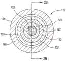
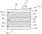
图2A示意性地描绘根据本文所示和所述的一或更多个实施方案的光扩散光纤的横截面;2A schematically depicts a cross-section of a light diffusing optical fiber in accordance with one or more embodiments shown and described herein;
图2B示意性地描绘根据本文所示和所述的一或更多个实施方案的光扩散光纤的另一个横截面;Figure 2B schematically depicts another cross-section of a light diffusing optical fiber in accordance with one or more embodiments shown and described herein;
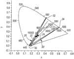
图3用图形描绘根据本文所示和所述的一或更多个实施方案的CIE 1931色度空间;Figure 3 graphically depicts the CIE 1931 chromaticity space in accordance with one or more embodiments shown and described herein;
图4用图形描绘根据本文所示和所述的一或更多个实施方案的CIE 1976色度空间;Figure 4 graphically depicts the CIE 1976 chromaticity space in accordance with one or more embodiments shown and described herein;
图5是描绘根据本文所示和所述的一或更多个实施方案的制造用于光扩散光纤的磷光体层的方法的流程图;5 is a flowchart depicting a method of fabricating a phosphor layer for a light diffusing optical fiber in accordance with one or more embodiments shown and described herein;
图6是展示具有老化的缓冲器的光扩散光纤样本和没有插入老化的管材中的缓冲器的纤维中的扩散长度和散射效率的变化的图表;6 is a graph showing the change in diffusion length and scattering efficiency in a light diffusing fiber sample with an aged buffer and a fiber without a buffer inserted in the aged tubing;
图7是展示老化之后的老化PVC管材的散射效率的图表;Figure 7 is a graph showing the scattering efficiency of aged PVC pipe after aging;
图8是展示在老化之后因为PVC和Apolhya材料的降级导致的CIE 1976色度空间中的色点变化(Duv)的图表;Figure 8 is a graph showing the color point change (Duv) in the CIE 1976 chromaticity space due to degradation of PVC and Apolhya materials after aging;
图9是展示因为具有作为缓冲器的磷光体层的光扩散纤维中的蓝光的损失的色点偏移(以Duv为单位)的图表,其中色变温度(CCT)大约4500K;9 is a graph showing the color point shift (in Duv) due to loss of blue light in a light diffusing fiber with a phosphor layer as a buffer, where the color change temperature (CCT) is approximately 4500K;
图10是展示老化之后的用于包括EVA材料的光扩散纤维样本的色点变化的图表;并且FIG. 10 is a graph showing the change in color point for a sample of light diffusing fibers including EVA material after aging; and
图11是展示用于图10的光扩散纤维的CCT变化的图表。FIG. 11 is a graph showing CCT variation for the light diffusing fiber of FIG. 10 .
具体实施方式Detailed ways
现参考图1、图2A和图2B,示意性地描绘照明系统100,所述照明系统包含光扩散光纤110,所述光扩散光纤光学耦合到光输出装置150,所述光输出装置包括光源152。光扩散光纤110包含第一末端112、与第一末端112相对的第二末端114、芯120、包围芯120的包层122、次级散射层132、磷光体层140、外表面128,和多个散射结构125,所述多个散射结构定位在芯120、包层122,或者芯120和包层122两者内。多个散射结构125被构造来朝着光扩散光纤110的外表面128散射引导光(例如,沿着光扩散光纤110从第一末端112和第二末端114中的一个朝着第一末端112和第二末端114中的另一个传播的由光输出装置150输出的光),使得引导光的一部分沿着光扩散光纤110的扩散长度扩散通过外表面128。如本文所使用,“扩散长度”是沿着光扩散光纤110的长度从光扩散光纤110的第一末端112(或从接收输入光的任何末端)延伸到引导光的90%已从光扩散光纤110扩散的位置的光扩散光纤110的长度。在一或更多个实施方案中,扩散长度可为从第一末端112到第二末端114的纤维的长度的10%或更大、20%或更大、30%或更大、40%或更大、50%或更大、60%或更大、70%或更大、80%或更大、90%或更大、95%或更大,或约100%。此外,磷光体层140被构造来改变通过磷光体层140扩散的引导光的颜色,使得从光扩散光纤110的外表面128向外发射的光(例如,发射光)包含白色或近白色光,如本文更详细地描述。Referring now to FIGS. 1 , 2A, and 2B, an
仍然参考图1、图2A和图2B,“外表面128”指的是光扩散光纤110的最外层表面。例如,在图2A和图2B中所描绘的实施方案中,外表面128是磷光体层140的表面,然而,应理解,其他实施方案可包含与磷光体层140径向向外间隔的另外层,例如,另外的透明涂层、护套等等,使得外表面128是光扩散光纤110的不同层的表面。此外,如本文所使用,“光扩散”意味光散射是沿着光扩散光纤110的长度的至少一部分大致上空间连续的,即,不存在实质性跳跃或不连续性诸如与离散(例如,点)散射相关联的那些跳跃或不连续性。因而,如本公开中阐述的大致连续光发射或大致连续光散射的概念指的是空间连续性。Still referring to FIGS. 1 , 2A, and 2B, “
如图1中所描绘,光输出装置150光学耦合到光扩散光纤110的第一末端112,使得由光输出装置150的光源152输出的光可照射光扩散光纤110的第一末端112的末端面116并且进入光扩散光纤110。在一些实施方案中,另外的光输出装置150可光学耦合到光扩散光纤110,例如,耦合到光扩散光纤110的第二末端114。光源152可包含发光二极管(light-emitting diode;LED)、激光二极管等等。例如,光源152可包含多模激光二极管、单模激光二极管、SiP激光二极管、VCSEL激光二极管,或另一种类型的半导体激光二极管。As depicted in FIG. 1 , the
在一些实施方案中,光源152可被构造来生成在200nm到2000nm波长范围内的光。例如,光源152可为紫外(ultraviolet;UV)或近UV光源,所述UV或近UV光源被构造来以自约300nm至约550nm、自约320nm至约550nm、自约340nm至约550nm、自约350nm至约550nm、自约360nm至约550nm、自约380nm至约550nm、自约400nm至约550nm、自约300nm至约540nm、自约300nm至约530nm、自约300nm至约520nm、自约300nm至约500nm、自约300nm至约480nm、自约300nm至约460nm、自约300nm至约450nm、自约300nm至约440nm、自约300nm至约420nm、自约300nm至约410nm或自约390nm至约410nm的波长发射光。示例性波长包括例如约300nm、325nm、350nm、375nm、400nm、405nm、415nm、425nm、435nm、445nm、450nm、475nm、500nm、525nm、550nm等等。光输出装置150可进一步包含另外的光学部件诸如透镜、光学输送纤维等,所述另外的光学部件定位在光源152与光扩散光纤110的第一末端112之间并且光学耦合到所述光源和所述第一末端,以便于将光输入到光扩散光纤110中。此外,这些另外的光学部件,诸如光学输送纤维,可允许光源152与光扩散光纤110空间分离。In some embodiments, the
在操作中,因为由光源152发射的光通过光扩散光纤110散射到周围环境中,所以光源152可定位在远离光扩散光纤110的位置处。因此,由光源152生成的任何热可远离光源152传递到远离光源152和光扩散光纤110两者的位置。因而,光扩散光纤110的温度可保持大致上类似于周围环境的周围温度,并且可将照明单元描述为热学上“冷”照明单元。此外,将光扩散光纤110和光源152空间分离可向照明系统100提供额外的设计灵活性。In operation, the
再次参考图1、图2A和图2B,在一些应用中,希望从光扩散光纤110输出白光。例如,被构造来输出一致白光的光扩散光纤110可被用作使用在LCD背光电子装置、其他电子装置,或白光的任何其他已知或尚未开发的应用中的CCFL的替换。此外,被构造来输出白光的光扩散光纤110可为有利的,因为光扩散光纤110比以前用来输出白光的发光装置(诸如CCFL)细得多(例如,包含小直径),从而允许本文所描述的光扩散光纤110用来照明小部件,诸如电子装置的薄基板。Referring again to Figures 1, 2A and 2B, in some applications it is desirable to output white light from the
虽然不意图受理论限制,但光(例如,由光输出装置150的光源152发射的光和从光扩散光纤110向外散射的光)的颜色可通过其色度表征。如本文所使用,“色度”指的是独立于亮度的光的颜色的质量。色度是类似物的颜色的色调和饱和度的组合,其中色调指的是由观察者感知的颜色(例如,红、橙、绿、蓝等),并且饱和度指的是颜色的鲜艳度或暗淡度,例如,颜色与灰阶或颜色的纯色的接近程度。While not intending to be bound by theory, the color of light (eg, light emitted by
现参考图3和图4,色度可被标绘在色度空间上,所述色度空间例如CIE 1931色度空间(图3)或CIE 1976色度空间(图4)。这些色度空间的部分在本文中称为“色度区域”。虽然不意图受理论限制,但是CIE 1931色度空间使用色度座标x和y描绘色度,所述色度座标基于如由the Commission Internationale de l'Eclairage(CIE)设定的标准三原色值(XYZ),参见本文以引用方式整体并入的T.Smith及J.Guild,The C.I.E.ColorimetricStandards and Their Use,33TRANS.Op.Soc.73-134(1931)。虽然不意图受理论限制,但是三原色值是用以唯一地表示可感知色调的数学构造,并且源自于原色(primary color)的相对强度。此外,虽然仍然不意图受理论限制,但是三原色值可被转换成色度座标x和y,以使用CIE 1931色度空间在二维座标中描绘色度。Referring now to Figures 3 and 4, chromaticity may be plotted on a chromaticity space, such as the CIE 1931 chromaticity space (Figure 3) or the CIE 1976 chromaticity space (Figure 4). Portions of these chrominance spaces are referred to herein as "chroma regions." While not intending to be bound by theory, the CIE 1931 chromaticity space depicts chromaticity using chromaticity coordinates x and y, which are based on standard tristimulus values as set by the Commission Internationale de l'Eclairage (CIE) (XYZ), see T. Smith and J. Guild, The C.I.E. Colorimetric Standards and Their Use, 33 TRANS. Op. Soc. 73-134 (1931), herein incorporated by reference in its entirety. While not intending to be bound by theory, the primary color value is a mathematical construct used to uniquely represent a perceivable hue, and is derived from the relative intensities of the primary colors. Furthermore, while still not intending to be bound by theory, the three primary color values can be converted to chromaticity coordinates x and y to depict chromaticity in two-dimensional coordinates using the CIE 1931 chromaticity space.
此外,CIE 1976色度空间使用座标u'和v'描绘色度,所述座标表示感知色度(例如,由观察者感知的色度)中的差异。u'和v'座标可源自于CIE 1931色度空间的x和y座标,并且可用来将色度中的差异展示为几何距离。因而,u'和v'座标可用来空间上表示一个色度与另一个色度如何不同。CIE 1976色度空间更详细地描述于本文以引用方式整体并入的Colorimetry,第二版:CIE publication 15.2,Vienna:Bureau Central CIE,1986中。Furthermore, the CIE 1976 chromaticity space depicts chromaticity using coordinates u' and v', which represent differences in perceived chromaticity (eg, as perceived by an observer). The u' and v' coordinates can be derived from the x and y coordinates of the CIE 1931 chromaticity space, and can be used to show differences in chromaticity as geometric distances. Thus, the u' and v' coordinates can be used to spatially represent how one chromaticity differs from another. The CIE 1976 chromaticity space is described in more detail in Colorimetry, Second Edition: CIE publication 15.2, Vienna: Bureau Central CIE, 1986, which is hereby incorporated by reference in its entirety.
虽然仍然不意图受理论限制,但是CIE 1931色度空间和CIE 1976色度空间两者描绘“普朗克轨迹(planckian locus)”,所述普朗克轨迹表示当在一定温度范围内加热黑体时由黑体发射的光的色度。如以下所描述,普朗克轨迹提供色度空间内的白光和近白光的参考位置。虽然不意图受理论限制,但是“黑体”指的是吸收所有电磁辐射包含照射黑体的波长范围,例如可见光的波长的理论对象。因为黑体吸收电磁辐射,所以黑体也在绝对零度以上(例如,在0°开尔文(K)以上)的温度处发射电磁辐射While still not intending to be bound by theory, both the CIE 1931 chromaticity space and the CIE 1976 chromaticity space describe the "planckian locus" which represents when a black body is heated over a range of temperatures The chromaticity of light emitted by a black body. As described below, the Planckian locus provides reference positions for white and near-white light within chromaticity space. While not intending to be bound by theory, "blackbody" refers to a theoretical object that absorbs all electromagnetic radiation, including the wavelength range that illuminates the blackbody, such as the wavelengths of visible light. Because black bodies absorb electromagnetic radiation, they also emit electromagnetic radiation at temperatures above absolute zero (eg, above 0° Kelvin (K))
此外,由黑体发射的电磁辐射为白的或近白的,并且这个发射的白电磁辐射或近白电磁辐射的特定色度和光谱分布取决于黑体的温度。黑体发射的温度被称为“色温”,并且每个色温限定位于普朗克轨迹上的光的色度(例如,每个色温限定位于普朗克轨迹上的光的特定白色度或近白色度)。虽然不意图受理论限制,但是在黑体的温度增加时,光谱分布朝着较短波长偏移,并且因而,对于较高的温度,色度朝着蓝色调偏移,并且对于较低的温度,色度朝着红色调偏移。Furthermore, the electromagnetic radiation emitted by a black body is white or near-white, and the specific chromaticity and spectral distribution of this emitted white or near-white electromagnetic radiation depends on the temperature of the black body. The temperature at which a black body emits is referred to as a "color temperature," and each color temperature defines the chromaticity of light lying on the Planck locus (eg, each color temperature defines a particular whiteness or near-whiteness of light lying on the Planckian locus) ). While not intending to be bound by theory, as the temperature of the blackbody increases, the spectral distribution shifts toward shorter wavelengths, and thus, for higher temperatures, the chromaticity shifts toward blue hues, and for lower temperatures, The chromaticity is shifted towards red hues.
此外,虽然色温限定位于普朗克轨迹上的光的色度,但其他色度(例如,感兴趣的色度)可通过“相关色温”限定,所述相关色温是当普朗克轨迹是使用CIE 1976色度空间的u'-v'座标标绘时普朗克轨迹上最接近感兴趣的色度的点的色温(因为u'-v'座标将色度中的差异空间上表示为几何距离)。此外,如本文所使用,CIE 1976色度空间上在感兴趣的的色度与最接近普朗克轨迹上的感兴趣的的色度的点之间延伸和/或延伸穿过所述感兴趣的色度和所述点(例如,在最接近普朗克轨迹上的感兴趣的的色度的点处垂直于切线延伸)的线被称为“等温线”。沿着等温线的每个色度点具有相同相关色温。Furthermore, while color temperature defines the chromaticity of light that lies on the Planckian locus, other chromaticities (eg, the chromaticity of interest) may be defined by the "correlated color temperature," which is when the Planckian locus is used The color temperature of the point on the Planck locus closest to the chromaticity of interest when the u'-v' coordinates of the CIE 1976 chromaticity space are plotted (since the u'-v' coordinates spatially represent the difference in chromaticity is the geometric distance). Furthermore, as used herein, the CIE 1976 chromaticity space extends between and/or through the chromaticity of interest and the point closest to the chromaticity of interest on the Planck locus The line between the chromaticity of and the point (eg, extending perpendicular to the tangent at the point closest to the chromaticity of interest on the Planck locus) is called an "isothermal line". Each chromaticity point along the isotherm has the same correlated color temperature.
如本文所使用,色度空间(例如,CIE 1931色度空间或CIE 1976色度空间)上的两个色度点之间的无量纲距离被称为“色度距离”。例如,当将测量色度与目标色度比较时,色度距离可使用可用来限定CIE 1931色度空间或CIE 1976色度空间上的其间的距离。一个示例性色度距离是感兴趣的的色度与普朗克轨迹上最接近感兴趣的的色度的点之间的距离(例如,沿着等温线测量的距离),所述距离在本文中和在本领域中被称为距离u-v或“Duv”。Duv是正或负无量纲数,其中正Duv涉及CIE 1976色度空间上的普朗克轨迹上方的点,并且负Duv涉及CIE 1976色度空间上的普朗克轨迹下方的点。虽然Duv是一个示例性色度距离,但是应理解色度距离可指的是色度空间上的任何两个点之间或色度空间上的点与色度空间上的线(诸如等温线)之间的距离。作为一个非限制实例,可在单独色度点与表示特定颜色座标温度的等温线之间测量色度距离(例如,色度点与沿着等温线的任何位置之间的最短距离)。作为另一非限制实例,可在两个单独色度点之间测量色度距离。As used herein, the dimensionless distance between two chromaticity points on a chromaticity space (eg, CIE 1931 chromaticity space or CIE 1976 chromaticity space) is referred to as a "chromaticity distance." For example, when comparing the measured chromaticity to the target chromaticity, the chromaticity distance may be used to define the distance in between on the CIE 1931 chromaticity space or the CIE 1976 chromaticity space. An exemplary chromaticity distance is the distance between the chromaticity of interest and the point on the Planck locus closest to the chromaticity of interest (eg, the distance measured along the isotherm), described herein Neutralization is known in the art as distance u-v or "Duv". Duv is a positive or negative dimensionless number, where positive Duv refers to points above the Planckian locus on the CIE 1976 chromaticity space and negative Duv refers to points below the Planckian locus on the CIE 1976 chromaticity space. While Duv is an exemplary chromaticity distance, it should be understood that chromaticity distance may refer to any two points on chromaticity space or between a point on chromaticity space and a line on chromaticity space, such as an isotherm distance between. As one non-limiting example, a chromatic distance (eg, the shortest distance between a chromaticity point and any location along the isotherm) can be measured between an individual chromaticity point and an isotherm representing the temperature of a particular color coordinate. As another non-limiting example, the chromaticity distance can be measured between two separate chromaticity points.
现参考图2A和图2B,描绘了光扩散光纤110的实施方案的截面,所述光扩散光纤包含芯120、包围芯120的包层122、次级散射层132、磷光体层140,和多个散射结构125。芯120可包含玻璃芯,例如,二氧化硅、锗掺杂的二氧化硅、氟掺杂的二氧化硅。此外,芯120包含折射率n。在一些实施方案中,芯120的折射率可为自约1.3至约1.5,例如,在589nm波长处,钠D-线(sodium D-line)的1.35、1.4、1.42、1.44、1.45、1.458、1.46、1.48等等。此外,在一或更多个实施方案中,芯120可具有自约10μm至约600μm的半径。在一些实施方案中,芯120的半径为自约30μm至约400μm。在其他实施方案中,芯120的半径为约125μm至约300μm。在仍然其他实施方案中,芯120的半径为约50μm、60μm、70μm、80μm、90μm、100μm、120μm、140μm、160μm、170μm、180μm、200μm、220μm、240μm,或250μm。Referring now to Figures 2A and 2B, a cross-section of an embodiment of a light diffusing
在一或更多个实施方案中,包层122可为玻璃包层,例如,纯二氧化硅、F掺杂的二氧化硅,或F(氟)/B(硼)共同掺杂的二氧化硅,或聚合物包层。在一个实施方案中,包层122包含低折射率聚合材料诸如UV或可热固化的氟化丙烯酸酯,诸如可从SSCP Co.Ltd 403-2,Moknae,Ansan,Kyunggi,Korea获得的PC452,或硅酮。在其他实施方案中,包层122包含氨基甲酸酯丙烯酸酯(urethane acrylate),诸如由DSM Desotech,Elgin,111制造的CPC6。在一些实施方案中,包层122包含高模量涂层。In one or more embodiments, cladding 122 may be a glass cladding, eg, pure silica, F-doped silica, or F(fluorine)/B(boron) co-doped dioxide Silicon, or polymer cladding. In one embodiment, the
如图2A和图2B中所描绘,包层122与芯120直接接触地包围芯120。包层122大体从芯120的外半径延伸。在本文所描述的一些实施方案中,包层的径向宽度大于约10μm、大于约20μm、大于约50μm,或大于约70μm。在一些实施方案中,包层122具有约10μm、20μm、30μm、40μm、50μm、60μm、70μm、80μm、90μm,或100μm的厚度。包层122大体具有小于芯120的折射率的折射率。As depicted in FIGS. 2A and 2B , cladding 122 surrounds
虽然不意图受理论限制,但由具有低折射率的材料形成包层122可增加光扩散光纤110的数值孔径(NA)。例如,光扩散光纤110可包含约0.3或更大、0.4或更大、0.5或更大等等的NA。While not intending to be bound by theory, forming the
在一或更多个实施方案中,包层122是具有相对于芯(例如,二氧化硅玻璃)为负的相对折射率的低折射率聚合物包层。例如,相对于芯的包层的相对折射率可小于约-0.5%,并且在一些实施方案中小于-1%。In one or more embodiments, the
在一或更多个实施方案中,包层122具有相对于芯为正的相对折射率。例如,相对于芯的包层的相对折射率可大于约0.5%,并且在一些实施方案中大于约1%。In one or more embodiments, the
在一些实施方案中,芯120、包层122,或两者可包括上掺杂剂或下掺杂剂。如本文所使用,“上掺杂剂”是具有相对于纯无掺杂二氧化硅使折射率上升的倾向的掺杂剂,并且“下掺杂剂”是具有相对于纯无掺杂二氧化硅使折射率降低的倾向的掺杂剂。例如,包层122包含用诸如例如氟的下掺杂剂下掺杂的二氧化硅玻璃。此外,光扩散光纤110将可包含自约0.15m至约100m,例如,约100m、75m、50m、40m、30m、20m、10m、9m、8m、7m、6m、5m、4m、3m、2m、1m、0.75m、0.5m、0.25m、0.15m,或0.1m的长度(例如,第一末端112与第二末端114之间的长度)。In some embodiments, the
仍然参考图2A和图2B,散射结构125可包含孔隙,诸如气体填充的孔隙,和/或散射粒子,诸如陶瓷材料、掺杂剂等等。散射结构125可遍及芯120设置(如图2A和图2B中所描绘),或可设置在芯120和包层122的界面(例如,芯-包层边界)附近,或可以环形圈设置在芯120内。具有散射结构125(也称为“随机空气线”或“纳米结构”或“纳米大小的结构”)的光扩散光纤110的一些实例描述于美国专利第7,450,806号中,并且描述于美国专利申请序列号12/950,045、13/097,208和13/269,055中,所述美国专利在本文中以引用方式整体并入。或者,光扩散光纤110可具有“粗糙化”芯120,其中在芯-包层边界处的芯120的表面上的不规则引起光散射。也可以利用其他类型的光扩散光纤。Still referring to Figures 2A and 2B, the scattering
散射结构125用来使在光扩散光纤110的芯120中传播的光散射,使得光被从芯120径向向外导向穿过外表面128,借此照明光扩散光纤110和包围光扩散光纤110的空间。虽然不意图受理论限制,但可通过增加散射结构125的浓度,遍及光扩散光纤110定位散射结构125,或在散射结构125限于定位在芯120、包层122,或两者内的环形圈的情况下,增加包含散射结构125的环形圈的宽度并且保持散射结构125的相同密度来增加散射导致的衰减。另外,在散射结构125为螺旋形的组成中,也可以通过在光扩散光纤110的长度上改变螺旋形散射结构125的节距来增加散射导致的衰减。具体来说,已经发现具有较小节距的螺旋形散射结构125比具有较大节距的螺旋形散射结构125散射更多的光。如本文所使用,螺旋形散射结构125的节距是指螺旋形散射结构125每单位长度缠绕在光扩散光纤110的长轴周围或在所述长轴周围旋转的次数的倒数。The
在操作中,光扩散光纤110可经历约0.2dB/m或更大,例如在照明波长(例如,发射辐射的波长(多个))处的自约0.5dB/m或更大、0.6dB/m或更大、0.7dB/m或更大、0.8dB/m或更大、0.9dB/m或更大、1dB/m或更大、1.2dB/m或更大、1.4dB/m或更大、1.6dB/m或更大、1.8dB/m或更大、2.0dB/m或更大、2.5dB/m或更大、3.0dB/m或更大、3.5dB/m或更大、4dB/m或更大、5dB/m或更大、6dB/m或更大、7dB/m或更大、8dB/m或更大、9dB/m或更大、10dB/m或更大、15dB/m或更大、20dB/m或更大、25dB/m或更大、30dB/m或更大、35dB/m或更大、40dB/m或更大、45dB/m或更大、50dB/m或更大、55dB/m或更大、60dB/m或更大等等的散射导致的衰减(即,因为通过光扩散光纤110的外表面128丢失的光导致,并不因为芯120内的散射粒子的吸收导致的衰减)。在一些实施方案中,光扩散光纤110的平均散射损失的变化在光扩散光纤110的任何给定纤维分段上,例如,在自约0.2m至约50m,例如,0.5m、1m、2m、5m、10m、15m、20m、25m、30m、35m、40m、45m等的任何给定纤维分段上不超过40%、不超过35%、不超过30%或不超过20%(即,散射损失在平均散射损失的±40%内,例如在±35%内、在±30%内、在±25%内、在±20%内、在±15%内,或在±10%内)。In operation, the
在散射结构125包含气体填充的孔隙的实施方案中,光扩散光纤110可包含大量气体填充的孔隙,例如光扩散光纤110的横截面中的多于50、大于100,或大于200个孔隙。气体填充的孔隙可含有例如SO2、Kr、Ar、CO2、N2、O2,或其混合物,所述气体降低芯120、包层122,或包括气体填充的的孔隙的芯-包层边界的区域中的平均折射率。此外,多个散射结构125诸如孔隙可随机地或非周期性地设置在芯120、包层122,或芯-包层边界中,然而,在其他实施方案中可周期性地设置孔隙。此外,气体填充的孔隙可与光扩散光纤110的长度平行。In embodiments where the
散射结构125诸如气体填充的孔隙的横截面大小(例如,直径)可为自约10nm至约10μm,并且长度可自约1μm变化至约50m。在一些实施方案中,孔隙(或其他散射结构125)的横截面大小为在自约10nm至约9μm、自约10nm至约8μm、自约10nm至约6μm、自约10nm至约5μm、自约10nm至约4μm、自约10nm至约2μm、自约20nm至约10μm、自约40nm至约10μm、自约50nm至约10μm、自约60nm至约10μm、自约80nm至约10μm、自约2μm至约10μm、自约4μm至约10μm、自约6μm至约10μm,或自约8μm至约10μm的范围内(例如,为约10nm、20nm、30nm、40nm、50nm、60nm、70nm、80nm、90nm、100nm、120nm、140nm、160nm、180nm、200nm、250nm、300nm、400nm、500nm、600nm、700nm、800nm、1μm、2μm、3μm、4μm、5μm、6μm、7μm、8μm、9μm,或约10μm)。在一些实施方案中,散射结构125(例如,孔隙)的长度为在自约1μm至约40m、自约1μm至约30m、自约1μm至约20m、自约1μm至约15m、自约1μm至约10m、自约1μm至约8m、自约1μm至约6m、自约1μm至约5m、自约1μm至约4m、自约1μm至约2m、自约1cm至约50m、自约10cm至约50m、自约20cm至约50m、自约30cm至约50m、自约40cm至约50m、自约50cm至约50m、自约60cm至约50m、自约70cm至约50m、自约80cm至约50m、自约90cm至约50m、自约1m至约50m、自约5m至约50m、自约10m至约50m、自约15m至约50m、自约20m至约50m、自约30m至约50m,或自约40m至约50m的范围内(例如,为约1μm、2μm、3μm、4μm、5μm、6μm、7μm、8μm、9μm、10μm、20μm、30μm、40μm、50μm、60μm、70μm、80μm、90μm、100μm、200μm、300μm、400μm、500μm、600μm、700μm、800μm、900μm、1000μm、5mm、10mm、50mm、100mm、500mm、1m、5m、10m、20m,或50m)。The cross-sectional size (eg, diameter) of the scattering
此外,可利用各种技术形成本文所描述的光扩散光纤110。例如,可通过将诸如孔隙或粒子的散射结构125合并到光扩散光纤110中的许多方法制作芯120。例如,用于形成具有孔隙的光纤预制件的方法描述于例如以引用方式并入本文的美国专利申请序列号11/583,098中。形成孔隙的另外的方法可见于例如以引用方式并入本文的美国申请序列号12/950,045、13/097,208,和13/269,055中。一般来说,光扩散光纤110是用纤维拉紧系统自光纤预制件拉制而成并且沿着大致上垂直路径退出拉制炉。在一些实施方案中,光扩散光纤110在其被拉制时旋转以沿着纤维的长轴生产螺旋形孔隙。在光扩散光纤110退出拉制炉时,非接触式瑕疵检测器可用来检查光扩散光纤110的可能已在光扩散光纤110的制造期间发生的损坏和/或瑕疵。此后,可用非接触式传感器测量光扩散光纤110的直径。在沿着垂直路径拉制光扩散光纤110时,光扩散光纤110可视情况被拉过冷却系统,所述冷却系统在将涂层(例如,二次散射层132、磷光体层140等)施加至光扩散光纤110之前冷却光扩散光纤110。Furthermore, the
在光扩散光纤110退出拉制炉或可选的冷却系统之后,光扩散光纤110进入至少一个涂布系统,其中一或更多个层(即,包层包含聚合物的实施方案中的包层122、二次散射层132,和/或磷光体层140)被施加至光扩散光纤110。在光扩散光纤110退出涂布系统时,可用非接触式传感器测量光纤的直径。此后,非接触式瑕疵检测器用来检查光扩散光纤110的可能已在光扩散光纤110的制造期间发生的涂层中的损坏和/或瑕疵。After the
仍然参考图2A和图2B,将二次散射层132定位成包围芯120,包层122,并且被构造来增强从芯120和借此包层122径向发射的光的分布和/或性质。此外,二次散射层132可根据观察角度促进自磷光体层140输出的一致颜色。二次散射层132大体自包层122的外半径延伸。在本文所描述的一些实施方案中,二次散射层132的径向宽度大于约1μm、2μm、3μm、4μm、5μm、6μm、7μm、8μm、9μm、10μm、20μm、30μm、40μm、50μm、60μm、70μm、80μm、90μm,或100μm。在一些实施方案中,二次散射层132与包层122直接接触,并且在其他实施方案中,二次散射层132与包层122径向隔开,例如,一或更多个额外层可定位在包层122与二次散射层132之间(诸如涂层130)或空气间隙可定位在包层122与二次散射层132之间。Still referring to FIGS. 2A and 2B , the
二次散射层132包括基体材料(例如,聚合物)及定位在基体材料中的散射材料(例如,散射剂)。在一些实施方案中,基体材料包含聚合物,例如,液体聚合物或散射剂可添加到其中的预聚合物材料,例如,由DSM Desotech,Elgin,111制造的基于丙烯酸酯的聚合物,诸如CPC6,或基于硅酮的聚合物。此外,在制造期间,二次散射层132可作为液体施加至光扩散光纤110,并且然后在施加至光扩散光纤110之后转换成固体。The
散射材料包含具有来自二次散射层132的基体材料(例如基体聚合物)的折射率差,例如,多于0.05的折射率差(例如,基体材料与散射材料之间的折射率差异大于0.05)的材料。在一些实施方案中,基体材料与散射材料之间的折射率差异为至少0.1。也就是说,散射材料的折射率可比二次散射层132的基体材料(例如,聚合物或其他基质材料的基体材料)的折射率大至少0.1。在操作中,散射材料提供从光扩散光纤110的芯120散射的光的角度独立的分布。The scattering material includes a refractive index difference from the matrix material (eg, matrix polymer) of the
散射材料可为固体粒子(例如,有机或无机固体粒子)、液体小滴,或气体气泡。示例性固体有机粒子包括颜料、聚合物,或可作为粉末合并到基体材料中的任何有机材料。如果散射材料是无机的,则散射粒子可为例如颜料、氧化物,或矿物填料。有机或无机散射粒子两者可由研磨固体生成,或最初可包含小粒子(例如,来自乳液聚合或溶胶凝胶)。在一些实施方案中,固体散射粒子是无机氧化物如二氧化硅(SiO2)、氧化铝(Al2O3)、氧化锆(ZrO2)、二氧化钛(TiO2)、二氧化铈(CeO2)、氧化锡(SnO2),和氧化锑(Sb2O3)。例如,基于二氧化钛的散射粒子可为白色油墨。研磨玻璃、陶瓷,或玻璃-陶瓷也可用作散射粒子。研磨硅酸盐或矿物填料如石英、滑石、富铝红柱石、堇青石、粘土、霞石正长岩、碳酸钙、三水合铝、硫酸钡、硅灰石(wallastonite)、云母、长石、叶蜡石、硅藻土、珍珠岩和方石英可在二次散射层132中用作散射材料。Scattering materials can be solid particles (eg, organic or inorganic solid particles), liquid droplets, or gas bubbles. Exemplary solid organic particles include pigments, polymers, or any organic material that can be incorporated into a matrix material as a powder. If the scattering material is inorganic, the scattering particles may be, for example, pigments, oxides, or mineral fillers. Both organic or inorganic scattering particles can be generated from ground solids, or can initially contain small particles (eg, from emulsion polymerization or sol-gel). In some embodiments, the solid scattering particles are inorganic oxides such as silica (SiO2 ), alumina (Al2 O3 ), zirconia (ZrO2 ), titania (TiO2 ), ceria (CeO2 ) ), tin oxide (SnO2 ), and antimony oxide (Sb2 O3 ). For example, the titanium dioxide based scattering particles may be white inks. Ground glass, ceramic, or glass-ceramic can also be used as scattering particles. Ground silicate or mineral fillers such as quartz, talc, mullite, cordierite, clay, nepheline syenite, calcium carbonate, aluminum trihydrate, barium sulfate, wallastonite, mica, feldspar, Pyrophyllite, diatomaceous earth, perlite, and cristobalite may be used as scattering materials in the
此外,散射材料可通过结晶和/或相分离原地生成,例如,聚乙烯、聚丙烯、间规聚苯乙烯、尼龙、聚对苯二甲酸乙二酯、聚酮,和聚氨酯,其中氨基甲酸乙酯官能基在凝固期间对准并结晶。例如,在变成二次散射层132的材料的固化或凝固期间,可形成充当光散射部位的晶体。此外,当二次散射层132固化且/或凝固时,散射层的材料(例如,基体材料和散射材料)可变得不相容,从而使材料相分离,进而形成可使光散射的小滴或粒子,因而形成散射部位。这些的实例将为,但不限于,苯乙烯-丁二烯苯-乙烯嵌段共聚物、聚苯乙烯中的聚甲基丙烯酸甲酯,和丙烯腈-丁二烯-苯乙烯共聚物。Additionally, scattering materials can be generated in situ by crystallization and/or phase separation, for example, polyethylene, polypropylene, syndiotactic polystyrene, nylon, polyethylene terephthalate, polyketone, and polyurethane, among which urethane The ethyl ester functionality aligns and crystallizes during solidification. For example, during curing or solidification of the material that becomes the
散射材料的平均直径可自约200nm至约10μm,例如,300nm、400nm、500nm、600nm、700nm、800nm、900nm、1μm、2μm、3μm、4μm、5μm、6μm、7μm、8μm、9μm、10μm等等。在其中散射材料包含散射粒子的实施方案中,二次散射层132内的散射粒子的横截面大小可包含0.1λ至10λ,其中λ是穿过光扩散光纤110传播的光的波长。在一些实施方案中,散射粒子的横截面大小大于0.2λ并且小于5λ,例如,在0.5λ与2λ之间。散射粒子的量可自约0.005重量%变化到70重量%,例如,0.01%至60%、0.02%至50%,等等。一般来说,二次散射层132越薄,越大量的散射粒子应存在于二次散射层132内。The average diameter of the scattering material can be from about 200 nm to about 10 μm, eg, 300 nm, 400 nm, 500 nm, 600 nm, 700 nm, 800 nm, 900 nm, 1 μm, 2 μm, 3 μm, 4 μm, 5 μm, 6 μm, 7 μm, 8 μm, 9 μm, 10 μm, etc. . In embodiments in which the scattering material comprises scattering particles, the cross-sectional size of the scattering particles within the
散射粒子的浓度可沿着光扩散光纤110的长度变化,或可为恒定的并且可为足以提供光的均匀(例如,独立于角度的)散射的重量百分比。在一些实施方案中,散射层中的散射粒子的重量百分比包含自约1重量%至约50重量%(例如,约1%、2%、3%、4%、5%、6%、7%、8%、9%、10%、11%、12%、13%、14%、15%、16%、17%、18%、19%、20%、25%、30%、35%、40%、45%,或50%)。在一些实施方案中,散射材料可包含二次散射层132内的子层。例如,在一些实施方案中,子层可具有约1μm至约5μm的厚度。The concentration of scattering particles may vary along the length of the
在操作中,二次散射层132可在大角度范围上(例如,40°至120°,或30°至130°,或15°至150°)促进一致的角度散射。例如,未散射的引导光在传播方向10上自光输出装置150沿着光扩散光纤110传播。展示了以散射角度θS在方向12上退出光扩散光纤110的散射光,所述散射角度为沿着光扩散光纤110传播的引导光的传播方向10与散射光离开光扩散光纤110时的所述散射光的方向12之间的角度差异。在一些实施方案中,当散射角度θS在15°与150°,或30°与130°之间时的光谱的强度为如在峰值波长处测量的±50%、±30%、±25%、±20%、±15%、±10%,或±5%内。在一些实施方案中,当散射角度θS在30°与130°或40°与120°内的所有角度之间时的光谱的强度至少在峰值波长处测量的±50%,例如±30%、±25%、±20%、±15%、±10%,或±5%内。因此,光扩散光纤110被构造来由于散射而提供大致上一致的照明,使得对于至少40度与110度之间的所有观察角度(例如,传播方向10与观察者的观察位置之间的角度),例如对于40度与120度之间的所有观察角度,最小散射照明强度与最大散射照明强度之间的差异小于最大散射照明强度的50%。根据一些实施方案,最小散射照明强度与最大散射照明强度之间的差异不大于最大散射照明强度的30%。In operation, the
如图2A和图2B中所描绘,光扩散光纤110可进一步包含一或更多个另外的层,例如,涂层、护套等等。例如,光扩散光纤110可另外包含涂层130,所述涂层可为包围芯120和包层122以便于机械搬运的大致上透明层,例如聚合物涂层。涂层130可包括在其中二次散射层132是在光扩散光纤110的初始拉制之后施加的实施方案中,以用于搬运问题。As depicted in Figures 2A and 2B, the light diffusing
仍然参考图2A和图2B,磷光体层140包围芯120、包层122,和二次散射层132。在一些实施方案中,磷光体层140与二次散射层132间隔开,并且空气间隙135定位于其间。在其他实施方案中,磷光体层140可与二次散射层132直接接触。磷光体层140可为用来作为保护层提供另外的功能的缓冲管材或护套,然而,应理解,磷光体层140不限于缓冲管材或护套并且可设置在光扩散光纤110的包层与外表面128之间的任何径向位置处。磷光体层140可包含约1.5mm或更小,例如,约1.4mm、1.3mm、1.2mm、1.1mm、1.0mm、0.9mm、0.8mm、0.7mm、0.6mm、0.5mm、0.4mm等等的外径,并且可包含200μm或更大,例如,约210μm或更大、220μm或更大、230μm或更大、240μm或更大、250μm或更大、300μm或更大、400μm或更大、500μm或更大、600μm或更大、700μm或更大、800μm或更大、900μm或更大、1.0mm或更大、1.1mm或更大、1.2mm或更大、1.3mm或更大等等的内径。此外,磷光体层140可包含自约200μm与约400μm,例如,约225μm、250μm、275μm、300μm、325μm、350μm、375μm等等的厚度。Still referring to FIGS. 2A and 2B ,
磷光体层140包含基体材料和混合到基体材料中的两种或更多种磷光体(例如,荧光或磷光材料)。基体材料可包含聚合物,例如液体聚合物、预聚合物材料等等。示例性聚合物包括基于丙烯酸酯或基于硅酮的聚合物(例如,CPC6二次涂层)。在一些实施方案中,例如,其中磷光体层140包含缓冲管材的实施方案,基体材料包含热塑性聚合物,例如聚烯烃,诸如聚乙烯、聚丙烯或来自Arkema Corporation的


在一或更多个实施方案中,光扩散纤维包括聚合物层,所述聚合物层被选择来以隔离方式或作为光扩散光纤的部分抵抗这样的老化。在一或更多个实施方案中,选择聚合物,使得在通过将纤维放置在具有85℃的温度和85%相对湿度的腔室中持续100小时、持续100小时至500小时,或高达2000小时使光扩散纤维老化之后,并且在光源光学耦合到第一末端之后,光扩散纤维展现改变了约20%或更少(例如,18%或更少、16%或更少、15%或更少、14%或更少、12%或更少、10%或更少、8%或更少、6%或更少、5%或更少、4%或更少或2%或更少)的光学损失。换句话说,老化之前的光扩散光纤的光学损失和老化(如本文所描述)之后的光扩散光纤的光学损失改变20%或更少。In one or more embodiments, the light diffusing fiber includes a polymer layer selected to resist such aging in isolation or as part of the light diffusing fiber. In one or more embodiments, the polymer is selected such that it can be used for 100 hours, for 100 hours to 500 hours, or up to 2000 hours by placing the fibers in a chamber having a temperature of 85°C and 85% relative humidity After aging the light diffusing fiber, and after optical coupling of the light source to the first end, the light diffusing fiber exhibits a change of about 20% or less (eg, 18% or less, 16% or less, 15% or less) , 14% or less, 12% or less, 10% or less, 8% or less, 6% or less, 5% or less, 4% or less or 2% or less) optical loss. In other words, the optical loss of the light diffusing fiber before aging and the optical loss of the light diffusing fiber after aging (as described herein) change by 20% or less.
在一或更多个实施方案中,选择聚合物,使得在通过将纤维放置在具有85℃的温度和85%相对湿度的腔室中持续100小时、持续100小时至500小时,或高达2000小时使光扩散纤维老化之后,并且在光源光学耦合到第一末端之后,光扩散纤维沿着自420nm至800nm的光谱范围展现改变了约10%或更少(例如,9%或更少、8%或更少、7%或更少、6%或更少、5%或更少、4%或更少、3%或更少,或2%或更少)的散射效率。换句话说,老化之前的光扩散光纤的散射效率和老化(如本文所描述)之后的光扩散光纤的散射效率改变10%或更少。In one or more embodiments, the polymer is selected such that it can be used for 100 hours, for 100 hours to 500 hours, or up to 2000 hours by placing the fibers in a chamber having a temperature of 85°C and 85% relative humidity After aging the light diffusing fiber, and after optical coupling of the light source to the first end, the light diffusing fiber exhibits a change of about 10% or less (eg, 9% or less, 8% along the spectral range from 420 nm to 800 nm) or less, 7% or less, 6% or less, 5% or less, 4% or less, 3% or less, or 2% or less) scattering efficiency. In other words, the scattering efficiency of the light diffusing fiber before aging and the scattering efficiency of the light diffusing fiber after aging (as described herein) change by 10% or less.
在一或更多个实施方案中,选择聚合物,使得在通过将纤维放置在具有85℃的温度和85%相对湿度的腔室中持续100小时、持续100小时至500小时,或高达2000小时使光扩散纤维老化之后,并且在光源光学耦合到第一末端之后,光扩散纤维展现改变小于20%(例如,18%或更少、16%或更少、15%或更少、14%或更少、13%或更少、12%或更少、10%或更少、8%或更少或5%或更少)的发光效率。换句话说,老化之前的光扩散光纤的发光效率和老化(如本文所描述)之后的光扩散光纤的发光效率改变小于20%。In one or more embodiments, the polymer is selected such that it can be used for 100 hours, for 100 hours to 500 hours, or up to 2000 hours by placing the fibers in a chamber having a temperature of 85°C and 85% relative humidity After aging the light diffusing fiber, and after optical coupling of the light source to the first end, the light diffusing fiber exhibits a change of less than 20% (eg, 18% or less, 16% or less, 15% or less, 14% or less, 13% or less, 12% or less, 10% or less, 8% or less, or 5% or less). In other words, the luminous efficiency of the light diffusing fiber before aging and the luminous efficiency of the light diffusing fiber after aging (as described herein) change by less than 20%.
在一或更多个实施方案中,选择聚合物,使得在将纤维放置在具有85℃的温度和85%相对湿度的腔室中持续100小时、持续100小时至500小时,或高达2000小时使光扩散纤维老化之后,并且在光源光学耦合到第一末端之后,光扩散纤维在沿着其长度的纤维的任何给定部分处展现改变小于约25%(例如,24%或更少、22%或更少、20%或更少、18%或更少、16%或更少、15%或更少、14%或更少、12%或更少、10%或更少、8%或更少,或5%或更少)的亮度。换句话说,老化之前的在沿着其长度的纤维的任何给定部分处的光扩散光纤的亮度和老化(如本文所描述)之后的沿着其长度的纤维的任何给定部分处的光扩散光纤的亮度改变小于约25%。在光扩散或穿透缓冲管材或二次涂层时,色温(CCT)在环境测试或老化(如本文所描述)之后可改变。在本公开的一或更多个实施方案中,光纤具有在7000K处小于400K,或在2500K处小于200K的CCT变化。在一或更多个实施方案中,发射光具有CIE 1976色度空间中的色点,所述色点在老化之后不改变。在一或更多个特定实施方案中,色点自老化之前的原始色点偏移或改变到老化之后的以Duv为单位的约0.02或更少,或0.01或更少的色点。在一或更多个实施方案中,具有目标管材壁的厚度(即在100μm与400μm之间)的聚合物的整体吸收率变化不超过15%、不超过10%,或不超过7%。将吸收率变化测量测试应用于筛选适用于磷光体缓冲管材和二次涂层材料的材料或含有磷光体材料的所有聚合物材料,或者在将蓝光降频转换成磷光体发射之后的光的路径上进行吸收率变化测量测试。在没有磷光体的情况下针对磷光体管材材料进行类似测试。In one or more embodiments, the polymer is selected such that the fiber is placed in a chamber with a temperature of 85°C and 85% relative humidity for 100 hours, for 100 hours to 500 hours, or up to 2000 hours. After aging of the light diffusing fiber, and after optical coupling of the light source to the first end, the light diffusing fiber exhibits a change of less than about 25% (eg, 24% or less, 22%) at any given portion of the fiber along its length or less, 20% or less, 18% or less, 16% or less, 15% or less, 14% or less, 12% or less, 10% or less, 8% or more less, or 5% or less) brightness. In other words, the brightness of the light diffusing fiber at any given portion of the fiber along its length before aging and the light at any given portion of the fiber along its length after aging (as described herein) The brightness change of the diffused fiber is less than about 25%. Color temperature (CCT) may change after environmental testing or aging (as described herein) as light diffuses or penetrates buffer tubing or secondary coatings. In one or more embodiments of the present disclosure, the fiber has a CCT variation of less than 400K at 7000K, or less than 200K at 2500K. In one or more embodiments, the emitted light has a color point in the CIE 1976 chromaticity space that does not change after aging. In one or more specific embodiments, the color point is shifted or changed from the original color point before aging to a color point in Duv after aging of about 0.02 or less, or 0.01 or less. In one or more embodiments, the overall absorbance of the polymer with the thickness of the target pipe wall (ie, between 100 μm and 400 μm) varies by no more than 15%, no more than 10%, or no more than 7%. Apply absorbance change measurement testing to screening materials suitable for phosphor buffer tubes and secondary coating materials or all polymeric materials containing phosphor materials, or the path of light after down-conversion of blue light to phosphor emission The absorbance change measurement test was carried out on . Similar tests were performed on phosphor tube materials without phosphor.
在一或更多个特定实施方案中,聚合物包含乙烯乙酸乙烯酯(ethylene vinylacetate(EVA))、聚四氟乙烯(polytetrafluoroethylene(PTFE))、乙烯四氟乙烯(ethylenetetrafluoroethylene(ETFE))、氟化乙烯丙烯(fluorinated ethylene propylene(FEP))、聚碳酸酯,和共聚酯中的任一种。在一或更多个特定实施方案中,聚合物层包含EVA。与抗老化性有关的先前描述和实施方案在聚合物不包括任何磷光体材料的情况下适用。因此,当视情况包括磷光体材料时并且当聚合物层基本上无磷光体材料时,如本文所描述的聚合物层展现抗老化性。In one or more specific embodiments, the polymer comprises ethylene vinylacetate (EVA), polytetrafluoroethylene (PTFE), ethylenetetrafluoroethylene (ETFE), fluorinated Any of fluorinated ethylene propylene (FEP), polycarbonate, and copolyester. In one or more specific embodiments, the polymer layer comprises EVA. The previous descriptions and embodiments related to aging resistance apply where the polymer does not include any phosphor material. Thus, a polymer layer as described herein exhibits aging resistance when optionally including phosphor material and when the polymer layer is substantially free of phosphor material.
此外,磷光体层140可包含具有混合在其中的二或更多个磷光体的聚合物涂层和/或缓冲层(例如,热塑性聚合物涂层和/或缓冲层)。Additionally,
磷光体层140的二或更多个磷光体可包含任何有机或无机荧光或发磷光材料,例如二或更多个磷光体可包含诸如Ce-YAG、Nd-YAG等等的石榴石磷光体组成、氮化物磷光体组成、原硅酸盐磷光体组成、硫硒化物磷光体组成、量子点、纳米粒子、有机荧光团的金属增强荧光等等。在一些实施方案中,二或更多个磷光体包含至少一个红磷光体和至少一个黄磷光体。虽然不意图受理论限制,但黄磷光体包括硫硒化物磷光体组成和石榴石磷光体组成,诸如Ce-YAG、Nd-YAG等等,并且红磷光体包括氮化物磷光体组成和原硅酸盐磷光体组成。此外,量子点可为黄磷光体或红磷光体。The two or more phosphors of the
在一些实施方案中,磷光体层140进一步包括散射材料,诸如以上关于二次散射层132所描述的散射材料。在这些实施方案中,磷光体层140可执行二次散射层132的一致角度散射功能,使得可从光扩散光纤110省去二次散射层132。然而,应理解光扩散光纤110的一些实施方案包括二次散射层132和磷光体层140两者,所述磷光体层包含散射材料。虽然不意图受理论限制,但将散射材料包括在磷光体层140中可增加光扩散光纤110的相互作用长度。如本文所使用,“相互作用长度”是指单独光子当横穿通过光扩散光纤110的一或更多个层诸如磷光体层140时将行进的平均路径长度。例如,将散射材料包括在磷光体层140中可导致比磷光体层140的厚度大高达约3倍的相互作用长度。In some embodiments,
二或更多个磷光体可共同地包含磷光体层140的约5%至约45%,例如,约6%、7.5%、8%、10%、12.5%、15%、20%、25%、30%、35%、40%等等,并且基体材料可包含磷光体层140的约55%至约85%,例如,约60%、65%、70%、75%、80%等等。此外,基体材料和二或更多个磷光体中的每个磷光体可以“组成比”混合,如本文所使用,所述组成比是指基体材料、二或更多个磷光体中的磷光体(例如,第一磷光体和第二磷光体),和在一些实施方案中,散射材料中每一个的相对量。作为说明,一个示例性实施方案可包含聚合物基体材料、红磷光体、黄磷光体,和散射材料,并且组成比可包括基体材料的73.8%、红磷光体的10%、黄磷光体的15%,和散射材料的1.2%,诸如二氧化钛。Two or more phosphors may collectively comprise from about 5% to about 45% of
虽然不意图受理论限制,但是改变磷光体层140的特定组成(例如,特定基体材料和特定磷光体)和磷光体层140的组成比可改变通过磷光体层140从芯120向外散射的发射光的所得色度。另外的因素可影响通过磷光体层140自芯120向外散射的发射光的所得色度,例如改变磷光体层140的厚度和改变通过光扩散光纤110的芯120传播的引导光的波长,例如,由光输出装置150的光源152输出的光。在一些实施方案中,当散射角度θS为自约10°至约170°时,发射光的色度在散射角度θS的情况下变化不超过±30%,例如,当散射角度θS为自约10°至约170°时,色度可在±30%、±25%、±20%、±15%、±10%,或±5%等等内变化。While not intending to be bound by theory, changing the particular composition of phosphor layer 140 (eg, a particular matrix material and a particular phosphor) and the composition ratio of
在一些实施方案中,形成磷光体层140包含将基体材料与二或更多个磷光体混合,然后将磷光体层140施加至光扩散光纤110。在一些实施方案中,磷光体层140可作为液体施加至光扩散光纤110,并且然后在施加之后转换成固体。此外,可为有效的是将二或更多个磷光体掺合到标准UV可固化丙烯酸酯基体材料中,所述标准UV可固化丙烯酸酯基体材料诸如Corning的标准CPC6二次光纤涂层。在一个实例中,可通过将30重量%的二或更多个磷光体与包含DSM950-111二次CPC6光纤涂层的基体材料混合,并且然后使混合物平移穿过滚轧机来形成磷光体层140。然而,应理解,基体材料可包含以上所描述的基体材料中的任何基体材料,例如,任何UV可固化丙烯酸酯聚合物。In some embodiments, forming the
在操作中,磷光体层140和具体来说,磷光体层140的二或更多个磷光体,将自芯120散射的光转换成较长波长的光。此外,磷光体层140改变自芯120散射的光的色度,使得退出磷光体层140以及自外表面128向外退出光扩散光纤110的发射光可包含所需要的颜色的光,诸如白光或近白光。例如,可通过将包含磷光体层140的光扩散光纤110光学耦合到较高能量(较低波长)光源152自光扩散光纤110发射白光,所述较高能量(较低波长)光源诸如以405nm或445nm发射的UV或近UV光源。在操作中,沿着光扩散光纤110的芯120传播的引导光(例如,由光源152输出的UV光)可自芯120散射,从而使磷光体层140的二或更多个磷光体发荧光或发磷光,使得UV光和这个发荧光或发磷光的发射波长的组合产生发射光,所述发射光为白的或近白的。此外,在包含磷光体层140中的两个磷光体的实施方案中,发射光可包含高达约80的显色指数(color rendering index),例如,自约71至约75的显色指数。此外,通过将磷光体层140中的磷光体的数目增加到三个或更多个,显色指数可增加到超过80。In operation,
再次参考图1-图4,从光扩散光纤110的外表面128向外输出的光包含由散射结构125朝着磷光体层140向外散射的沿着芯120传播的引导光,和由引导光通过磷光体层140的传播引起的散射荧光或磷光的组合,从而生产组合光,例如,发射光,所述组合光可具有在色度区域内的色度,使得发射光向观察者表现为所需要的颜色,诸如白色。Referring again to FIGS. 1-4 , the light output outward from the
例如,图3描绘了示例性磷光体层140的CIE 1931色度空间上的第一x-y色度区域20,所述示例性磷光体层具有包含黄磷光体(例如,Ce-YAG)的第一磷光体和包含红磷光体(例如,氮化物)的第二磷光体。第一x-y色度区域20从第一x-y边界线22延伸到第二x-y边界线24。第一x-y边界线22描绘了当磷光体层140包含仅基体材料和/或第一磷光体的组成时的可能色度,其中第一色度点30描绘了具有100%基体材料的磷光体层140的色度并且第二色度点32描绘了具有100%的第一磷光体的磷光体层140的色度。此外,第二x-y边界线24描绘了当磷光体层140包含仅基体材料和/或第二磷光体的组成时的可能色度,其中第一色度点30描绘了具有100%基体材料的磷光体层140的色度并且第三色度点34描绘了具有100%的第一磷光体的磷光体层140的色度。For example, FIG. 3 depicts a first
在一些实施方案中,第一色度点30可包含CIE 1931色度空间上自约(0.15,0.0)至约(0.25,0.0)的(x,y)点。第二色度点32可包含CIE 1931色度空间上约(0.4,0.6)的(x,y)点,并且第三色度点34可包含CIE 1931色度空间上来自约(0.6,0.4)的(x,y)点。虽然第一x-y色度区域20描绘了一个示例性x-y色度区域,但是应理解可设想被构造来实现其他x-y色度区域的解磷光体层140。通过改变这个示例性磷光体层140的组成比,第一x-y色度区域20内的任何色度是可能的。此外,图3还描绘了第二x-y色度区域20',所述第二x-y色度区域展示具有与第一x-y色度区域20的磷光体层140相同的组成但具有不同厚度的磷光体层140的可能色度。如由第二x-y色度区域20'所示,磷光体层140的厚度可改变穿过磷光体层140的光的所得色度。此外,磷光体层140可被构造,使得发射光的色度对于相对于引导光的传播方向10自约15°至约170°的所有观察角度位于x-y色度区域(诸如第一x-y色度区域20)内。In some implementations, the
此外,图4描绘了示例性磷光体层140的CIE 1976色度空间上的u'-v'色度区域50。u'-v'色度区域50由以距普朗克轨迹0.02Duv的距离平行于普朗克轨迹延伸的第一u'-v'边界线52、以距普朗克轨迹-0.02Duv的距离平行于普朗克轨迹延伸的第二u'-v'边界线54、沿着用于约2000K的相关色温的等温线在第一u'-v'边界线52与第二u'-v'边界线54之间延伸的第三u'-v'边界线56,和沿着用于约10000K的相关色温的等温线在第一u-v边界线52与第二u'-v'边界线54之间延伸的第四u'-v'边界线58限定。此外,发射光的色度对于相对于引导光的传播方向10的自约15°至约170°的所有观察角度位于u'-v'色度区域50内。In addition, FIG. 4 depicts the u'-v'
仍然参考图4,设想被构造来实现其他u'-v'色度区域的磷光体层140。例如,u'-v'色度区域由以距普朗克轨迹0.01Duv的距离平行于普朗克轨迹延伸的第一u'-v'边界线、以距普朗克轨迹-0.01Duv的距离平行于普朗克轨迹延伸的第二u'-v'边界线、沿着用于约2500K的相关色温的等温线在第一u'-v'边界线与第二u'-v'边界线之间延伸的第三u'-v'边界线,和沿着用于约8000K的相关色温的等温线在第一u'-v'边界线与第二u'-v'边界线之间延伸的第四u'-v'边界线限定。Still referring to FIG. 4, a
在一个示例性实施方案中,磷光体层140被构造来促进具有目标色度的发射光的发射,所述目标色度由在普朗克轨迹处或在距普朗克轨迹约±0.02Duv内的约5300K的颜色座标温度限定,所述磷光体层可包含约96%黄磷光体(例如,Ce-YAG)和约4%红磷光体(例如,氮化物)的磷光体混合物。此外,磷光体混合物可与基体材料和散射材料混合。例如,磷光体层140可包含约7.5%磷光体混合物、约1.2%散射材料(例如,二氧化钛),和约91.3%基体材料(例如,热塑性聚合物)。此外,在这个示例性实施方案中,磷光体层140可包含约260μm的厚度,并且当设置在光扩散光纤110上时,可包含约750μm的外径。In an exemplary embodiment, the
在另一示例性实施方案中,磷光体层140被构造来促进具有目标色度的发射光的发射,所述目标色度由在普朗克轨迹处或在距普朗克轨迹约±0.02Duv内的约3300K的颜色座标温度限定,所述磷光体层可包含约88%黄磷光体(例如,Ce-YAG)和约12%红磷光体(例如,氮化物)的磷光体粉末混合物。此外,磷光体混合物可与基体材料和散射材料混合。例如,磷光体层140可包含约12.5%磷光体混合物、约1.2%散射材料(例如,二氧化钛),和约86.8%基体材料(例如,热塑性聚合物)。此外,在这个示例性实施方案中,磷光体层140可包含约200μm的厚度,并且当设置在光扩散光纤110上时,可包含约630μm的外径。In another exemplary embodiment,
现参考图5,现在将具体参考图5的流程图200并且一般参考其他图来描述制造用于光扩散光纤110的磷光体层140的方法。流程图200描绘了若干方法步骤,所述方法步骤虽然以具体相继次序加以描述,但不限于那个相继次序。如以下所描述,方法可用来调谐磷光体层140的组成比和厚度,使得磷光体层140当由光源152照射时发射所需要的光色度。Referring now to FIG. 5 , a method of fabricating
首先,在步骤202处,方法包含形成第一测试磷光体层,所述第一测试磷光体层包含以第一组成比组合的基体材料(例如,以上所描述的基体材料中的一种的光学凝胶)、第一磷光体,和第二磷光体的组合。此外,第一测试磷光体层包含第一磷光体层厚度。在不意图受理论限制的情况下,单独磷光体层140的厚度和组成比两者改变穿过磷光体层140的光的色度。接下来,在步骤204处,方法包含例如通过用由光输出装置150的光源152输出的光照射第一测试磷光体层来导向光通过第一测试磷光体层。在步骤206处,方法包含例如使用用于测量色度的任何已知或尚未开发的测量装置来测量穿过第一测试磷光体层的所得光的色度(例如,“第一色度”)。First, at step 202, the method includes forming a first test phosphor layer comprising a matrix material (eg, an optical fiber of one of the matrix materials described above) combined in a first composition ratio gel), a first phosphor, and a combination of a second phosphor. Additionally, the first test phosphor layer includes a first phosphor layer thickness. Without intending to be bound by theory, both the thickness and composition ratio of the
接下来,在步骤208处,将第一色度与目标色度比较。在一些实施方案中,目标色度可为白或近白色度,例如,普朗克轨迹上或附近的色度。例如,目标色度可在CIE 1976色度空间上由以距普朗克轨迹0.02Duv的距离平行于普朗克轨迹延伸的第一边界线、以距普朗克轨迹-0.02Duv的距离平行于普朗克轨迹延伸的第二边界线、沿着用于约2000K的相关色温的等温线在第一边界线与第二边界线之间延伸的第三边界线,和沿着用于约10000K的相关色温的等温线在第一边界线与第二边界线之间延伸的第四边界线限定的的色度区域内。Next, at step 208, the first chromaticity is compared to the target chromaticity. In some implementations, the target chromaticity may be a white or near-white chromaticity, eg, a chromaticity on or near the Planckian locus. For example, the target chromaticity may be defined on the CIE 1976 chromaticity space by a first boundary line extending parallel to the Planck locus at a distance of 0.02 Duv from the Planck locus, parallel to the Planck locus at a distance of -0.02 Duv from the Planck locus A second boundary line extending from the Planck locus, a third boundary line extending between the first and second boundary lines along an isotherm for a correlated color temperature of about 2000K, and along a correlated color temperature for about 10000K The isotherm of is within a chromaticity region defined by a fourth boundary line extending between the first boundary line and the second boundary line.
仍然参考图5,如果第一色度在距目标色度的阈值色度距离内,例如,在CIE 1976色度空间上的±0.02、±0.01、±0.0075、±0.005、±0.0025、±0.001等等内,则方法移动到步骤218并且第一组成比可使用在磷光体层140的制造中以用于作为用于本文所描述的光扩散光纤110的涂层和/或缓冲管材使用。或者,如果第一色度不在阈值色度距离内,则方法移动到步骤210,所述步骤包含形成第二测试磷光体层,所述第二测试磷光体层包含以第二组成比组合的基体材料、第一磷光体,和第二磷光体的组合,所述第二组成比可不同于第一组成比(例如,第一测试磷光体层的组成比)。应理解,虽然关于阈值色度距离描述了图5的方法,但在其中目标色度是沿着普朗克轨迹的点的实施方案中,阈值色度距离可为阈值Duv。此外,第二测试磷光体层包含第二磷光体层厚度,所述第二磷光体层厚度在一些实施方案中不同于第一磷光体层厚度,例如,第二磷光体层厚度可大于或小于第一磷光体层厚度,并且如以上所描述,厚度变化可改变所得色度。应理解,第二测试磷光体层可具有相比于第一测试磷光体层的不同组成比、不同厚度,或不同组成比和不同厚度两者。Still referring to Figure 5, if the first chromaticity is within a threshold chromaticity distance from the target chromaticity, eg, ±0.02, ±0.01, ±0.0075, ±0.005, ±0.0025, ±0.001, etc. on the CIE 1976 chromaticity space etc., then the method moves to step 218 and the first composition ratio can be used in the manufacture of the
接下来,在步骤212处,方法包含例如使用光输出装置150的光源152导向光通过第二测试磷光体层,和在步骤214处,测量所得光的色度(例如,“第二色度”)。此外,在步骤216处,方法包含将第二色度与目标色度比较,并且如果第二色度在距目标色度的阈值色度距离内,则方法移动到步骤218并且第二组成比可用在磷光体层140的制造中用于作为光扩散光纤110的涂层和/或缓冲管材。Next, at step 212, the method includes directing light through the second test phosphor layer, eg, using the
在一些实施方案中,第二色度比第一色度更接近于目标色度,例如,第二色度可在CIE 1976色度空间上由以距普朗克轨迹0.02Duv的距离平行于普朗克轨迹延伸的第一边界线、以距普朗克轨迹-0.02Duv的距离平行于普朗克轨迹延伸的第二边界线、沿着用于约2000K的相关色温的等温线在第一边界线与第二边界线之间延伸的第三边界线,和沿着用于约10000K的相关色温的等温线在第一边界线与第二边界线之间延伸的第四边界线限定的色度区域内。或者,如果第二色度不在阈值色度距离内,则方法移动回到步骤210,并且形成另一测试磷光体层,所述另一磷光体层具有相比于第一测试磷光体层和第二测试磷光体层的不同组成比和/或厚度,并且可针对这个另外的组成比和/或厚度重复步骤212-216,直到找到使发射光具有在阈值色度距离内的色度的组成比和/或厚度。In some implementations, the second chromaticity is closer to the target chromaticity than the first chromaticity, eg, the second chromaticity may be parallel to the Planckian locus by a distance of 0.02 Duv from the Planckian locus on the CIE 1976 chromaticity space. A first boundary line extending from the Planck locus, a second boundary line extending parallel to the Planck locus at a distance of -0.02 Duv from the Planck locus, along the isotherm for a correlated color temperature of about 2000K at the first boundary line a third boundary line extending between the second boundary line and a chromaticity region defined by a fourth boundary line extending between the first and second boundary lines along an isotherm for a correlated color temperature of about 10,000 K . Alternatively, if the second chromaticity is not within the threshold chromaticity distance, the method moves back to step 210 and another test phosphor layer is formed having a Two different composition ratios and/or thicknesses of the phosphor layers are tested, and steps 212-216 may be repeated for this additional composition ratio and/or thickness until a composition ratio is found that gives the emitted light a chromaticity within the threshold chromaticity distance and/or thickness.
对根据本公开的一个实施方案的光扩散光纤的样本执行测试。将样本放置在护套中,所述护套包括紧密聚合物层或松散管材并且其中管材不包括聚合物层。样本通过暴露于85℃的温度和具有85℃的温度和85%相对湿度的腔室持续高达2000小时加以老化。Tests were performed on samples of light diffusing optical fibers according to one embodiment of the present disclosure. The sample is placed in a sheath that includes a tight polymer layer or loose tubing and wherein the tubing does not include a polymer layer. The samples were aged by exposure to a temperature of 85°C and a chamber with a temperature of 85°C and a relative humidity of 85% for up to 2000 hours.
评估就相对于输入光散射多少光而言的沿着自420nm至800nm的光谱范围的光扩散光纤的散射效率。输入光包括蓝LD光源(具有自445nm至455nm的波长)、绿LD(具有自520nm至532nm的波长)、红二极管(具有自630nm或650nm的波长),或宽带白光源(例如,等离子体激光源)。通过将光扩散纤维放置在大整合球形内侧来执行测试,并且通过检测器捕获所有散射光。通过以相同球形将光扩散纤维修剪至纤维的开始位置来测量输入光的量。The scattering efficiency of the light diffusing fiber along the spectral range from 420 nm to 800 nm was evaluated in terms of how much light was scattered relative to the input light. Input light includes blue LD light sources (with wavelengths from 445nm to 455nm), green LDs (with wavelengths from 520nm to 532nm), red diodes (with wavelengths from 630nm or 650nm), or broadband white light sources (eg, plasma lasers source). The test is performed by placing a light diffusing fiber inside a large integrating sphere, and all scattered light is captured by a detector. The amount of input light was measured by trimming the light diffusing fiber in the same spherical shape to the starting position of the fiber.
还使用整合球形测量管材透射,其中透射的光的量是从具有护套的纤维和没有护套的相同纤维测量。Tube transmission was also measured using an integrated sphere, where the amount of transmitted light was measured from the fiber with the jacket and the same fiber without the jacket.
测量老化之前和老化之后的来自样本的色点偏移。The color point shift from the samples before and after aging was measured.
纤维中测量的效率下降可为护套材料中的吸收增加和包层中的吸收增加的结果。后者可为一次涂层自身的降级的产物。其也可由缓冲材料的除气引起。在PVC材料的情况下,如图6中所示,散射效率下降的原因中的一个是包层降级。具体来说,图6展示具有老化的缓冲器的光扩散光纤样本和没有插入老化的管材中的缓冲器的纤维中的使用蓝输入光(具有自455nm至460nm的波长)的扩散长度和效率的变化。在两种情况下,老化包括暴露于85°和85%相对湿度处的腔室持续500小时。在图6中,关于老化之前和老化之后展示纤维散射效率下降(“效率下降”)、管材散射效率下降(“管材下降”)和扩散长度下降(“DL下降”)。另外,包层的脱层可引起光的较快速损失,从而导致较短的扩散长度,其中光强度下降10dB(或90%强度损失)(光扩散纤维的扩散长度),如图6中所示。The drop in efficiency measured in the fibers may be the result of increased absorption in the jacket material and increased absorption in the cladding. The latter may be the product of degradation of the primary coating itself. It can also be caused by outgassing of the buffer material. In the case of PVC material, as shown in Figure 6, one of the reasons for the decrease in scattering efficiency is cladding degradation. Specifically, Figure 6 shows the difference in diffusion length and efficiency using blue input light (with wavelengths from 455 nm to 460 nm) in a light diffusing fiber sample with an aged buffer and a fiber without a buffer inserted in the aged tubing Variety. In both cases, aging included exposure to the chamber at 85° and 85% relative humidity for 500 hours. In Figure 6, a decrease in fiber scattering efficiency ("Efficiency Decrease"), a decrease in tubing scattering efficiency ("Tube Decay"), and a decrease in diffusion length ("DL Decrease") are shown for before and after aging. Additionally, delamination of the cladding can cause a faster loss of light, resulting in a shorter diffusion length with a 10dB drop in light intensity (or 90% loss of intensity) (diffusion length of a light diffusing fiber), as shown in Figure 6 .
在具有护套(紧密缓冲器)的纤维的样本上测量扩散长度,并且在相同纤维上测量散射效率。在未老化纤维样本上测量护套的影响,所述未老化纤维样本放置在老化管材内侧。PVC的降级倾向于在自约60℃至约80℃的温度处发生。图7展示用于在80℃处持续498小时,和70℃处持续566小时的老化之后的老化PVC管材的散射效率的完全光谱。PVC管材放置在没有聚合物层的纤维上。这个范围内的较低温度处的降级被视为起因于PVC的除气,从而导致包层的脱层(不将所述脱层视为展现这类温度处的吸收损失)。在较高温度处,降级被视为起因于包层中的吸收增加,从而导致扩散长度和散射效率的减少。最后,在这个范围内的较高温度处,缓冲器开始吸收光,这是需要新护套材料,和可能不同的包层的主要原因。在缓冲层中的磷光体的情况下,在光谱的蓝部分处导致如图8中所示的色点偏移,并且在颜色转换中损失。图8展示当纤维以450nm光的300mW照亮时,在85℃处老化、在85℃和85%相对湿度处老化之后,因为PVC和Apolhya材料的降级导致的CIE 1976色度空间中的色点变化(Duv)。如图8中所示,最快速的降级在85℃和85%相对湿度处的老化之后发生。Diffusion lengths were measured on samples of fibers with jackets (tight buffers), and scattering efficiencies were measured on the same fibers. The effect of the jacket was measured on unaged fiber samples placed inside the aged tubing. Degradation of PVC tends to occur at temperatures from about 60°C to about 80°C. Figure 7 shows the full spectrum of scattering efficiency for aged PVC pipe after aging at 80°C for 498 hours, and 70°C for 566 hours. PVC pipes are placed on fibers without a polymer layer. Degradation at lower temperatures within this range is considered to result from outgassing of the PVC, resulting in delamination of the cladding (which is not considered to exhibit absorption losses at such temperatures). At higher temperatures, the degradation is seen to result from increased absorption in the cladding, resulting in a decrease in diffusion length and scattering efficiency. Finally, at higher temperatures in this range, the buffer begins to absorb light, which is the main reason for the need for new jacket material, and possibly a different cladding. In the case of phosphors in the buffer layer, a color point shift as shown in Figure 8 is caused at the blue part of the spectrum and is lost in color conversion. Figure 8 shows the color point in the CIE 1976 chromaticity space due to degradation of PVC and Apolhya materials after aging at 85°C, after aging at 85°C and 85% relative humidity when the fiber is illuminated with 300mW of 450nm light Variation (Duv). As shown in Figure 8, the fastest degradation occurred after aging at 85°C and 85% relative humidity.
为了克服降级,选择对于本文所描述的老化测试弹性较大的材料。这些老化测试通常是正常操作条件下的长期性能的预报器;然而,准确预测采用对于不同的材料可为不同的降解知识和模型。表1总结了用于不同热塑性材料的测试的结果,所述不同热塑性材料可用作光扩散光纤样本的缓冲器。用于良好性能的准则包括具有200μm的壁厚度的管材构型中的材料的充分初始透射率,和在85℃和85%相对湿度处的长期老化之后观察的透射的相对低的降级。To overcome degradation, materials that are more resilient to the aging tests described herein are selected. These aging tests are often predictors of long-term performance under normal operating conditions; however, accurate predictions employ knowledge and models of degradation that may differ for different materials. Table 1 summarizes the results of testing for different thermoplastic materials that can be used as buffers for samples of light diffusing optical fibers. Criteria for good performance included sufficient initial transmission of the material in a tubular configuration with a wall thickness of 200 μm, and relatively low degradation in transmission observed after long-term aging at 85° C. and 85% relative humidity.
表1.正规化到200μm壁厚度的440-460nm光谱带(用以指示发黄)处的具有放置在内侧的光扩散光纤样本的管材的吸收Table 1. Absorption of tubing with light diffusing fiber samples placed inside at the 440-460 nm spectral band (to indicate yellowing) normalized to 200 μm wall thickness

充分的透射效率意味初始透射大于90%(即吸收小于10%),并且在老化之后,透射效率是在自420nm至800nm的光谱范围内的80%-85%。材料的发黄将导致光谱的蓝色部分中的另外效率损失。这个测试限制诸如PVC的材料的一定范围。另外,用于具有作为缓冲器的磷光体层的光扩散纤维的色点偏移应展现发射光中的色点偏移,所述色点偏移以Duv为单位CIE 1976小于0.02或小于0.01。图6针对具有作为缓冲器的磷光体层的白色光扩散光纤展示Duv色点偏移与自445nm至455nm的波长处的透射之间的相关性。不同色点的合意性可需要蓝光透射率的不同量变化,以提供小于0.01的以Duv为单位的色点偏移。应相信,10%-15%的吸收率应在用于蓝透射的可接受范围内以实现这个色点偏移范围,如图9中所示。具体来说,图9是展示因为具有作为缓冲器的磷光体层的光扩散纤维中的蓝光的损失的色点偏移或色点变化(以Duv为单位),其中色变温度(CCT)大约4500K。0.01Duv的颜色偏移变化的变化对应于15%的透射下降。Sufficient transmission efficiency means that the initial transmission is greater than 90% (ie, the absorption is less than 10%), and after aging, the transmission efficiency is 80%-85% in the spectral range from 420 nm to 800 nm. Yellowing of the material will result in additional efficiency losses in the blue part of the spectrum. This test limits a certain range for materials such as PVC. Additionally, the color point shift for a light diffusing fiber with a phosphor layer as a buffer should exhibit a color point shift in the emitted light that is CIE 1976 less than 0.02 or less than 0.01 in Duv. Figure 6 shows the correlation between Duv color point shift and transmission at wavelengths from 445 nm to 455 nm for a white light diffusing fiber with a phosphor layer as a buffer. The desirability of different color points may require different amounts of changes in blue light transmittance to provide a color point shift in Duv of less than 0.01. It is believed that an absorptivity of 10%-15% should be within an acceptable range for blue transmission to achieve this color point shift range, as shown in FIG. 9 . Specifically, Figure 9 is a graph showing the color point shift or color point change (in Duv) due to loss of blue light in a light diffusing fiber with a phosphor layer as a buffer, where the color change temperature (CCT) is approximately 4500K. A change in color shift change of 0.01 Duv corresponds to a 15% drop in transmission.
表1含有在440nm-460nm处满足15%透射下降的材料的特定范围。最佳执行材料是氟化聚合物诸如PTFE、ETFE,和FEP。材料中的一些如EVA接近15%透射下降范围。具有EVA材料的作为缓冲器的热塑性磷光体层在85℃和85%相对湿度处老化持续2000小时。用于4900K CCT色点的色点变化在没有颜色转换效率的损失的情况下为小于0.01,如图10和图11中所示。图11展示用于相同样本的CCT变化,所述CCT变化小于或等于约10%。Table 1 contains specific ranges of materials that satisfy a 15% drop in transmission at 440nm-460nm. Best performing materials are fluorinated polymers such as PTFE, ETFE, and FEP. Some of the materials such as EVA are close to the 15% transmission drop range. The thermoplastic phosphor layer with EVA material as buffer was aged at 85°C and 85% relative humidity for 2000 hours. The color point variation for the 4900K CCT color point is less than 0.01 without loss of color conversion efficiency, as shown in FIGS. 10 and 11 . Figure 11 shows the CCT variation for the same sample that is less than or equal to about 10%.
本公开的方面(1)关于光扩散光纤,所述光扩散光纤包含:玻璃芯;包层,所述包层包围玻璃芯;磷光体层,所述磷光体层包围包层;以及多个散射结构,所述多个散射结构定位在玻璃芯、包层,或玻璃芯和包层两者内,其中:多个散射结构被构造来朝着光扩散光纤的磷光体层散射引导光,使得引导光的一部分沿着光扩散光纤的扩散长度扩散通过磷光体层,并且磷光体层包含二或更多个磷光体,并且被构造来将扩散通过磷光体层的引导光转换成发射光,使得发射光的颜色包含在CIE 1976色度空间上的u'-v色度区域内的色度,所述u'-v'色度区域由以下各项限定:第一u'-v'边界线,所述第一u'-v'边界线以距普朗克轨迹0.02Duv的距离平行于普朗克轨迹延伸;第二u'-v'边界线,所述第二u'-v'边界线以距普朗克轨迹-0.02Duv的距离平行于普朗克轨迹延伸;第三u'-v'边界线,所述第三u'-v'边界线沿着用于约2000K的相关色温的等温线在第一u'-v’边界线与第二u'-v边界线之间延伸;以及第四u'-v'边界线,所述第四u'-v'边界线沿着用于约10000K的相关色温的等温线在第一u'-v'边界线与第二u'-v'边界线之间延伸。Aspect (1) of the present disclosure relates to a light diffusing optical fiber comprising: a glass core; a cladding layer surrounding the glass core; a phosphor layer surrounding the cladding layer; and a plurality of scattering layers structure, the plurality of scattering structures are positioned within the glass core, the cladding, or both the glass core and the cladding, wherein: the plurality of scattering structures are configured to scatter direct light toward a phosphor layer of a light diffusing fiber such that the directing A portion of the light diffuses through the phosphor layer along the diffusion length of the light diffusing fiber, and the phosphor layer includes two or more phosphors and is configured to convert the guided light diffused through the phosphor layer into emitted light such that the emitted light is emitted The color of light contains the chromaticity within the u'-v chromaticity region on the CIE 1976 chromaticity space, the u'-v' chromaticity region being defined by: the first u'-v' boundary line, The first u'-v' boundary line extends parallel to the Planck locus at a distance of 0.02 Duv from the Planck locus; the second u'-v' boundary line, the second u'-v' boundary line Extends parallel to the Planckian locus at a distance of -0.02 Duv from the Planckian locus; third u'-v' boundary line along the isothermal for a correlated color temperature of about 2000K A line extends between a first u'-v' boundary line and a second u'-v boundary line; and a fourth u'-v' boundary line along a line for approximately An isotherm for a correlated color temperature of 10000K extends between the first u'-v' boundary line and the second u'-v' boundary line.
本公开的方面(2)关于方面(1)的光扩散光纤,其中二或更多个磷光体包含红磷光体和黄磷光体。Aspect (2) of the present disclosure relates to the light diffusing optical fiber of aspect (1), wherein the two or more phosphors comprise a red phosphor and a yellow phosphor.
本公开的方面(3)关于方面(1)的光扩散光纤,其中二或更多个磷光体包含磷光或荧光材料。Aspect (3) of the present disclosure relates to the light diffusing optical fiber of aspect (1), wherein the two or more phosphors comprise phosphorescent or fluorescent materials.
本公开的方面(4)关于方面(3)的光扩散光纤,其中磷光或荧光材料包含Ce-YAG、Nd-YAG、氮化物、原硅酸盐、硫硒化物、量子点、纳米粒子,或其组合。Aspect (4) of the present disclosure relates to the light diffusing optical fiber of aspect (3), wherein the phosphorescent or fluorescent material comprises Ce-YAG, Nd-YAG, nitride, orthosilicate, thioselenide, quantum dots, nanoparticles, or its combination.
本公开的方面(5)关于方面(1)至(4)中任一个的光扩散光纤,其中:磷光体层进一步包含聚合物基体材料;并且二或更多个磷光体设置在聚合物基体材料内。Aspect (5) of the present disclosure relates to the light diffusing optical fiber of any one of aspects (1) to (4), wherein: the phosphor layer further includes a polymer matrix material; and the two or more phosphors are disposed on the polymer matrix material Inside.
本公开的方面(6)关于方面(1)至(5)中任一个的光扩散光纤,其中散射材料设置在磷光体层内。Aspect (6) of the present disclosure relates to the light diffusing optical fiber of any one of aspects (1) to (5), wherein the scattering material is provided within the phosphor layer.
本公开的方面(7)关于方面(1)至(6)中任一个的光扩散光纤,其中磷光体层包含缓冲管材。Aspect (7) of the present disclosure relates to the light diffusing optical fiber of any one of aspects (1) to (6), wherein the phosphor layer includes a buffer tube.
本公开的方面(8)关于方面(1)至(7)中任一个的光扩散光纤,其中:发射光的色度在CIE 1976色度空间上位于内部的u'-v'色度区域的第一u'-v'边界线以距普朗克轨迹0.01Duv的距离平行于普朗克轨迹延伸;并且发射光的色度在CIE1976色度空间上位于内部的u'-v'色度区域的第二u'-v'边界线以距普朗克轨迹-0.01Duv的距离平行于普朗克轨迹延伸。Aspect (8) of the present disclosure relates to the light diffusing optical fiber of any one of aspects (1) to (7), wherein: the chromaticity of the emitted light is located in the inner u'-v' chromaticity region on the CIE 1976 chromaticity space The first u'-v' boundary line extends parallel to the Planckian locus at a distance of 0.01Duv from the Planckian locus; and the chromaticity of the emitted light is located in the inner u'-v' chromaticity region on the CIE1976 chromaticity space The second u'-v' boundary line runs parallel to the Planck locus at a distance of -0.01 Duv from the Planck locus.
本公开的方面(9)关于方面(1)至(8)中任一个的光扩散光纤,其中:发射光的色度在CIE 1976色度空间上位于内部的u'-v'色度区域的第三u'-v'边界线沿着用于约2500K的相关色温的等温线在第一u'-v'边界线与第二u'-v'边界线之间延伸;并且发射光的色度在CIE 1976色度空间上位于内部的u'-v'色度区域的第四u'-v'边界线沿着用于约8000K的相关色温的等温线在第一u'-v'边界线与第二u'-v'边界线之间延伸。Aspect (9) of the present disclosure relates to the light diffusing optical fiber of any one of aspects (1) to (8), wherein: the chromaticity of the emitted light is located in the inner u'-v' chromaticity region on the CIE 1976 chromaticity space The third u'-v' boundary line extends between the first u'-v' boundary line and the second u'-v' boundary line along the isotherm for a correlated color temperature of about 2500K; and the chromaticity of the emitted light The fourth u'-v' boundary line of the inner u'-v' chromaticity region on the CIE 1976 chromaticity space is along the isotherm for a correlated color temperature of about 8000K at the first u'-v' boundary line with The second u'-v' boundary line extends between.
本公开的方面(10)关于方面(1)至(9)中任一个的光扩散光纤,其中发射光的色度对于相对于引导光的传播方向自约15°至约170°的所有观察角度位于由第一u'-v'边界线、第二u'-v'边界线、第三u'-v'边界线,和u'-v第四边界线限定的位于CIE 1976色度空间上的u'-v'色度区域内。Aspect (10) of the present disclosure relates to the light diffusing fiber of any one of aspects (1) to (9), wherein the chromaticity of the emitted light is for all viewing angles from about 15° to about 170° with respect to the direction of propagation of the guided light On the CIE 1976 chromaticity space defined by the first u'-v' boundary line, the second u'-v' boundary line, the third u'-v' boundary line, and the u'-v fourth boundary line within the u'-v' chromaticity region.
本公开的方面(11)关于方面(1)至(10)中任一个的光扩散光纤,其中光扩散光纤发射具有沿着扩散长度的强度的光,所述强度变化不超过约20%。Aspect (11) of the present disclosure relates to the light diffusing fiber of any one of aspects (1) to (10), wherein the light diffusing fiber emits light having an intensity along the diffusion length that does not vary by more than about 20%.
本公开的方面(12)关于方面(1)至(11)中任一个的光扩散光纤,其中多个散射结构被构造来朝着光扩散光纤的磷光体层散射引导光,使得引导光的一部分沿着光扩散光纤的扩散长度扩散通过光扩散光纤的外表面,以提供约50dB/km或更大的散射导致的衰减。Aspect (12) of the present disclosure relates to the light diffusing optical fiber of any one of aspects (1) to (11), wherein the plurality of scattering structures are configured to scatter guide light toward a phosphor layer of the light diffusing fiber such that a portion of the light is guided Diffusion through the outer surface of the light-diffusing fiber along the diffusion length of the light-diffusing fiber to provide a scattering-induced attenuation of about 50 dB/km or greater.
本公开的方面(13)关于方面(1)至(12)中任一个的光扩散光纤,其中:光扩散光纤包含二次散射层,所述二次散射层包围玻璃芯和包层并且定位在包层与磷光体层之间;并且二次散射层包含基体材料和散射材料,并且被构造,使得对于40度与120度之间的所有观察角度,最小散射照明强度与最大散射照明强度之间的差异小于最大散射照明强度的50%。Aspect (13) of the present disclosure relates to the light diffusing optical fiber of any one of aspects (1) to (12), wherein the light diffusing optical fiber includes a secondary scattering layer surrounding the glass core and the cladding and positioned at the between the cladding layer and the phosphor layer; and the secondary scattering layer contains the matrix material and the scattering material and is constructed such that, for all viewing angles between 40 degrees and 120 degrees, between the minimum scattered illumination intensity and the maximum scattered illumination intensity The difference is less than 50% of the maximum diffuse illumination intensity.
本公开的方面(14)关于方面(13)的光扩散光纤,其中二次散射层直接接触磷光体层。Aspect (14) of the present disclosure relates to the light diffusing optical fiber of aspect (13), wherein the secondary scattering layer directly contacts the phosphor layer.
本公开的方面(15)关于方面(13)的光扩散光纤,其中二次散射层与磷光体层间隔开,使得空气间隙设置在二次散射层与磷光体层之间。Aspect (15) of the present disclosure relates to the light diffusing optical fiber of aspect (13), wherein the secondary scattering layer is spaced apart from the phosphor layer such that an air gap is provided between the secondary scattering layer and the phosphor layer.
本公开的方面(16)关于方面(13)至(15)中任一个的光扩散光纤,其中二次散射层的散射材料包含TiO2、SiO2、Al2O3、ZrO2、CeO2、SnO2、Sb2O3,或其组合。Aspect (16) of the present disclosure relates to the light diffusing optical fiber of any one of aspects (13) to (15), wherein the scattering material of the secondary scattering layer comprises TiO2 , SiO2 , Al2 O3 , ZrO2 , CeO2 , SnO2 , Sb2 O3 , or a combination thereof.
本公开的方面(17)关于方面(13)至(16)中任一个的光扩散光纤,其中二次散射层的基体材料包含聚合物。Aspect (17) of the present disclosure relates to the light diffusing optical fiber of any one of aspects (13) to (16), wherein the matrix material of the secondary scattering layer comprises a polymer.
本公开的方面(18)关于方面(1)至(17)中任一个的光扩散光纤,其中多个散射结构包含气体填充的孔隙。Aspect (18) of the present disclosure relates to the light diffusing optical fiber of any one of aspects (1) to (17), wherein the plurality of scattering structures comprise gas-filled apertures.
本公开的方面(19)关于方面(1)至(18)中任一个的光扩散光纤,其中包层包含聚合物。Aspect (19) of the present disclosure relates to the light diffusing optical fiber of any one of aspects (1) to (18), wherein the cladding comprises a polymer.
本公开的方面(20)关于照明系统,所述照明系统包含方面(1)至(19)中任一个的光扩散光纤,所述光扩散光纤光学耦合到光输出装置,所述光输出装置包含光源。Aspect (20) of the present disclosure pertains to an illumination system comprising the light-diffusing optical fiber of any one of aspects (1) to (19), the light-diffusing optical fiber being optically coupled to a light output device, the light output device comprising light source.
本公开的方面(21)关于方面(20)的照明系统,其中由光源输出并沿着光扩散光纤传播的光包含自约300nm至约460nm的波长。Aspect (21) of the present disclosure relates to the illumination system of aspect (20), wherein the light output by the light source and propagating along the light diffusing optical fiber comprises wavelengths from about 300 nm to about 460 nm.
方面(22)关于制造用于光扩散光纤的磷光体层的方法,方法包含:形成第一测试磷光体层,所述第一测试磷光体层包含以第一组成比组合的基体材料、第一磷光体,和第二磷光体的组合并且具有第一磷光体层厚度;导向光通过第一测试磷光体层;测量导向被通过第一测试磷光体层的光的第一色度;以及形成第二测试磷光体层,所述第二测试磷光体层包含以第二组成比组合的基体材料、第一磷光体,和第二磷光体的组合并且具有第二磷光体层厚度,其中:第二组成比不同于第一组成比;第二磷光体层厚度不同于第一磷光体层厚度;或者第二组成比和第二磷光体层厚度两者分别不同于第一组成比和第一磷光体层厚度,使得被导向通过第二测试磷光体层的光包含第二色度,所述第二色度比第一色度更接近于目标色度。Aspect (22) relates to a method of manufacturing a phosphor layer for a light diffusing optical fiber, the method comprising: forming a first test phosphor layer comprising a matrix material, a first test phosphor layer combined in a first composition ratio a phosphor, and a second phosphor in combination and having a first phosphor layer thickness; directing light through the first test phosphor layer; measuring a first chromaticity of light directed through the first test phosphor layer; and forming a Two test phosphor layers comprising a combination of a matrix material, a first phosphor, and a second phosphor combined in a second composition ratio and having a second phosphor layer thickness, wherein: the second The composition ratio is different from the first composition ratio; the second phosphor layer thickness is different from the first phosphor layer thickness; or both the second composition ratio and the second phosphor layer thickness are different from the first composition ratio and the first phosphor layer, respectively layer thickness such that the light directed through the second test phosphor layer contains a second chromaticity that is closer to the target chromaticity than the first chromaticity.
方面(23)关于方面(22)的方法,其中第一磷光体包含红磷光体并且第二磷光体包含黄磷光体。Aspect (23) relates to the method of aspect (22), wherein the first phosphor comprises a red phosphor and the second phosphor comprises a yellow phosphor.
方面(24)关于方面(22)的方法,其中第一磷光体和第二磷光体各自包含磷光或荧光材料。Aspect (24) relates to the method of aspect (22), wherein the first phosphor and the second phosphor each comprise a phosphorescent or fluorescent material.
方面(25)关于方面(24)的方法,其中磷光或荧光材料包含Ce-YAG、Nd-YAG、氮化物、原硅酸盐、硫硒化物、量子点、纳米粒子,或其组合。Aspect (25) relates to the method of aspect (24), wherein the phosphorescent or fluorescent material comprises Ce-YAG, Nd-YAG, nitride, orthosilicate, thioselenide, quantum dots, nanoparticles, or a combination thereof.
方面(26)关于方面(22)至(25)中任一个的方法,其中第二磷光体层厚度大于第一磷光体层厚度。Aspect (26) relates to the method of any of aspects (22) to (25), wherein the second phosphor layer thickness is greater than the first phosphor layer thickness.
方面(27)关于方面(22)至(26)中任一个的方法,其中第二磷光体层厚度小于第一磷光体层厚度。Aspect (27) relates to the method of any of aspects (22) to (26), wherein the second phosphor layer thickness is less than the first phosphor layer thickness.
方面(28)关于方面(22)至(27)中任一个的方法,其中第二色度和目标色度在CIE1976色度空间上的u'-v'色度区域内,所述u'-v'色度区域由以下各项限定:第一u'-v'边界线,所述第一u'-v'边界线以距普朗克轨迹0.02Duv的距离平行于普朗克轨迹延伸;第二u'-v'边界线,所述第二u'-v'边界线以距普朗克轨迹-0.02Duv的距离平行于普朗克轨迹延伸;第三u'-v'边界线,所述第三u'-v'边界线沿着用于约2000K的相关色温的等温线在第一u'-v’边界线与第二u'-v边界线之间延伸;以及第四u'-v'边界线,所述第四u'-v'边界线沿着用于约10000K的相关色温的等温线在第一u'-v'边界线与第二u'-v'边界线之间延伸。Aspect (28) relates to the method of any of aspects (22) to (27), wherein the second chromaticity and the target chromaticity are in the u'-v' chromaticity region on the CIE1976 chromaticity space, the u'- The v' chromaticity region is defined by: a first u'-v' boundary line extending parallel to the Planck locus at a distance of 0.02 Duv from the Planck locus; The second u'-v' boundary line, which extends parallel to the Planck locus at a distance of -0.02 Duv from the Planck locus; the third u'-v' boundary line, the third u'-v' boundary line extends between the first u'-v' boundary line and the second u'-v boundary line along an isotherm for a correlated color temperature of about 2000K; and a fourth u' -v' boundary line, the fourth u'-v' boundary line between the first u'-v' boundary line and the second u'-v' boundary line along the isotherm for a correlated color temperature of about 10000K extend.
方面(29)关于方面(22)至(28)中任一个的方法,其中第二色度和目标色度在CIE1931色度空间上的x-y色度区域内,所述x-y色度区域由以下各项限定:第一x-y边界线,所述第一x-y边界线自位于约(0.15,0.0)与(0.25,0.0)之间的第一x-y色度点和位于约(0.4,0.6)处的第二x-y色度点延伸;以及第二x-y边界线,所述第二x-y边界线自第一x-y色度点和位于约(0.6,0.4)处的第三x-y色度点延伸。Aspect (29) relates to the method of any of aspects (22) to (28), wherein the second chromaticity and the target chromaticity are within an x-y chromaticity region on the CIE1931 chromaticity space, the x-y chromaticity region being determined by each of the following Term Definition: A first x-y boundary line from a first x-y chromaticity point located between about (0.15, 0.0) and (0.25, 0.0) and a first x-y chromaticity point located at about (0.4, 0.6) two x-y chromaticity points extending; and a second x-y boundary line extending from the first x-y chromaticity point and a third x-y chromaticity point located at about (0.6,0.4).
本公开的方面(30)关于光扩散光纤,所述光扩散光纤包含:玻璃芯;包层,所述包层包围玻璃芯;磷光体层,所述磷光体层包围包层;以及多个散射结构,所述多个散射结构定位在玻璃芯、包层,或玻璃芯和包层两者内,其中:多个散射结构被构造来朝着光扩散光纤的磷光体层散射引导光,使得引导光的一部分沿着光扩散光纤的扩散长度扩散通过磷光体层,并且磷光体层包含二或更多个磷光体,并且被构造来将扩散通过磷光体层的引导光转换成发射光,使得发射光的颜色包含在CIE 1931色度空间上的x-y色度区域内的色度,所述x-y色度区域由以下各项限定:第一x-y边界线,所述第一x-y边界线自位于约(0.15,0.0)与(0.25,0.0)之间的第一x-y色度点和位于约(0.4,0.6)处的第二x-y色度点延伸;以及第二x-y边界线,所述第二x-y边界线自第一x-y色度点和位于约(0.6,0.4)处的第三x-y色度点延伸。Aspect (30) of the present disclosure relates to a light diffusing optical fiber comprising: a glass core; a cladding layer surrounding the glass core; a phosphor layer surrounding the cladding layer; and a plurality of scattering layers structure, the plurality of scattering structures are positioned within the glass core, the cladding, or both the glass core and the cladding, wherein: the plurality of scattering structures are configured to scatter direct light toward a phosphor layer of a light diffusing fiber such that the directing A portion of the light diffuses through the phosphor layer along the diffusion length of the light diffusing fiber, and the phosphor layer includes two or more phosphors and is configured to convert the guided light diffused through the phosphor layer into emitted light such that the emitted light is emitted The color of light contains the chromaticity within the x-y chromaticity region on the CIE 1931 chromaticity space, the x-y chromaticity region being defined by: a first x-y boundary line, the first x-y boundary line from about ( a first x-y chromaticity point between 0.15, 0.0) and (0.25, 0.0) and a second x-y chromaticity point extending at about (0.4, 0.6); and a second x-y boundary line, the second x-y boundary The line extends from the first x-y chromaticity point and the third x-y chromaticity point located at about (0.6,0.4).
方面(31)关于方面(30)的光扩散光纤,其中二或更多个磷光体包含红磷光体和黄磷光体。Aspect (31) relates to the light diffusing optical fiber of aspect (30), wherein the two or more phosphors comprise a red phosphor and a yellow phosphor.
方面(32)关于方面(30)的光扩散光纤,其中二或更多个磷光体包含磷光或荧光材料。Aspect (32) relates to the light diffusing optical fiber of aspect (30), wherein the two or more phosphors comprise phosphorescent or fluorescent materials.
方面(33)关于方面(32)的光扩散光纤,其中磷光或荧光材料包含Ce-YAG、Nd-YAG、氮化物、原硅酸盐、硫硒化物、量子点、纳米粒子,或其组合。Aspect (33) relates to the light diffusing fiber of aspect (32), wherein the phosphorescent or fluorescent material comprises Ce-YAG, Nd-YAG, nitride, orthosilicate, thioselenide, quantum dots, nanoparticles, or a combination thereof.
方面(34)关于方面(30)至(33)中任一个的光扩散光纤,其中:磷光体层进一步包含聚合物基体材料;并且二或更多个磷光体设置在聚合物基体材料内。Aspect (34) relates to the light diffusing optical fiber of any one of aspects (30) to (33), wherein: the phosphor layer further comprises a polymer matrix material; and the two or more phosphors are disposed within the polymer matrix material.
方面(35)关于方面(30)至(34)中任一个的光扩散光纤,其中散射材料设置在磷光体层内。Aspect (35) relates to the light diffusing optical fiber of any one of aspects (30) to (34), wherein the scattering material is disposed within the phosphor layer.
方面(36)关于方面(30)至(35)中任一个的光扩散光纤,其中磷光体层包含缓冲管材。Aspect (36) relates to the light diffusing optical fiber of any one of aspects (30) to (35), wherein the phosphor layer comprises a buffer tube.
方面(37)关于方面(30)至(36)中任一个的光扩散光纤,其中发射光的色度对于相对于引导光的传播方向自约15°至约170°的所有观察角度位于由第一x-y边界线和第二x-y边界线限定的位于CIE 1931色度空间上的x-y色度区域内。Aspect (37) relates to the light-diffusing optical fiber of any one of aspects (30) to (36), wherein the chromaticity of the emitted light is located from about 15° to about 170° with respect to the direction of propagation of the guided light for all viewing angles from about 15° to about 170°. An x-y boundary line and a second x-y boundary line lie within the x-y chromaticity region on the CIE 1931 chromaticity space.
方面(38)关于方面(30)至(37)中任一个的光扩散光纤,其中光扩散光纤发射具有沿着扩散长度的强度的光,所述强度变化不超过约20%。Aspect (38) relates to the light diffusing fiber of any one of aspects (30) to (37), wherein the light diffusing fiber emits light having an intensity along the diffusion length that does not vary by more than about 20%.
方面(39)关于方面(30)至(38)中任一个的光扩散光纤,其中多个散射结构被构造来朝着光扩散光纤的磷光体层散射引导光,使得引导光的一部分沿着光扩散光纤的扩散长度扩散通过光扩散光纤的外表面,以提供约50dB/km或更大的散射导致的衰减。Aspect (39) relates to the light diffusing optical fiber of any one of aspects (30) to (38), wherein the plurality of scattering structures are configured to scatter the directed light toward the phosphor layer of the light diffusing fiber such that a portion of the directed light follows the light The diffusion length of the diffusing fiber diffuses through the outer surface of the light diffusing fiber to provide scattering-induced attenuation of about 50 dB/km or greater.
方面(40)关于方面(30)至(39)中任一个的光扩散光纤,其中:光扩散光纤包含二次散射层,所述二次散射层包围玻璃芯和包层并且定位在包层与磷光体层之间;并且二次散射层包含基体材料和散射材料,并且被构造,使得对于40度与120度之间的所有观察角度,最小散射照明强度与最大散射照明强度之间的差异小于最大散射照明强度的50%。Aspect (40) relates to the light diffusing optical fiber of any one of aspects (30) to (39), wherein: the light diffusing optical fiber includes a secondary scattering layer surrounding the glass core and the cladding and positioned between the cladding and the cladding between the phosphor layers; and the secondary scattering layer contains the matrix material and the scattering material and is constructed such that for all viewing angles between 40 degrees and 120 degrees, the difference between the minimum scattered illumination intensity and the maximum scattered illumination intensity is less than 50% of maximum diffuse lighting intensity.
方面(41)关于方面(40)的光扩散光纤,其中二次散射层直接接触磷光体层。Aspect (41) relates to the light diffusing optical fiber of aspect (40), wherein the secondary scattering layer directly contacts the phosphor layer.
方面(42)关于方面(40)的光扩散光纤,其中二次散射层与磷光体层间隔开,使得空气间隙设置在二次散射层与磷光体层之间。Aspect (42) relates to the light diffusing optical fiber of aspect (40), wherein the secondary scattering layer is spaced apart from the phosphor layer such that an air gap is provided between the secondary scattering layer and the phosphor layer.
方面(43)关于方面(40)至(42)中任一个的光扩散光纤,其中二次散射层的散射材料包含TiO2、SiO2、Al2O3、ZrO2、CeO2、SnO2、Sb2O3,或其组合。Aspect (43) relates to the light diffusing optical fiber of any one of aspects (40) to (42), wherein the scattering material of the secondary scattering layer comprises TiO2 , SiO2 , Al2 O3 , ZrO2 , CeO2 , SnO2 , Sb2 O3 , or a combination thereof.
方面(44)关于方面(40)至(43)中任一个的光扩散光纤,其中二次散射层的基体材料包含聚合物。Aspect (44) relates to the light diffusing optical fiber of any one of aspects (40) to (43), wherein the matrix material of the secondary scattering layer comprises a polymer.
方面(45)关于方面(40)至(44)中任一个的光扩散光纤,其中多个散射结构包含气体填充的孔隙。Aspect (45) relates to the light diffusing optical fiber of any of aspects (40) to (44), wherein the plurality of scattering structures comprise gas-filled apertures.
方面(46)关于方面(30)至(45)中任一个的光扩散光纤,其中包层包含聚合物。Aspect (46) relates to the light diffusing optical fiber of any one of aspects (30) to (45), wherein the cladding comprises a polymer.
方面(47)关于照明系统,所述照明系统包含方面(30)至(46)中任一个的光扩散光纤,所述光扩散光纤光学耦合到光输出装置,所述光输出装置包含光源。Aspect (47) relates to an illumination system comprising the light diffusing fiber of any of aspects (30) to (46) optically coupled to a light output device, the light output device comprising a light source.
方面(48)关于方面(47)的照明系统,其中由光源输出并沿着光扩散光纤传播的光包含自约300nm至约460nm的波长。Aspect (48) relates to the illumination system of aspect (47), wherein the light output by the light source and propagating along the light diffusing fiber comprises wavelengths from about 300 nm to about 460 nm.
方面(49)关于光扩散光纤,所述光扩散光纤包含:第一末端、与第一末端相对的第二末端;第一末端112与第二末端114之间的长度;玻璃芯,所述玻璃芯沿着长度延伸;以及包层,所述包层包围玻璃芯的至少一部分;聚合物层,所述聚合物层包围包层;并且其中纤维被构造来朝着光扩散光纤的外表面散射沿着光扩散光纤传播的引导光,使得引导光的一部分沿着光扩散光纤的扩散长度扩散通过聚合物层,其中,在通过将纤维放置在具有85℃的温度和85%相对湿度的腔室中持续100小时、持续100小时至500小时,或高达2000小时使光扩散纤维老化之后,并且在光源光学耦合到第一末端之后,光扩散纤维展现以下各项中的任一个:改变约20%或更少的光损耗、改变约10%或更少的散射效率,和改变小于25%的沿着长度的纤维的任何给定部分处的亮度。Aspect (49) relates to a light diffusing optical fiber comprising: a first end, a second end opposite the first end; a length between the
方面(50)关于方面(49)的光扩散光纤,进一步包含多个散射结构,所述多个散射结构定位在玻璃芯、包层,或玻璃芯和包层两者内,其中多个散射结构被构造来朝着光扩散光纤的外表面散射引导光,使得引导光的一部分沿着光扩散光纤的扩散长度扩散通过聚合物层,所述引导光被转换成具有CIE 1976色度空间中的色点的发射光,其中在老化之后,色点偏移约0.02或更少。Aspect (50) relates to the light diffusing optical fiber of aspect (49), further comprising a plurality of scattering structures positioned within the glass core, the cladding, or both the glass core and the cladding, wherein the plurality of scattering structures Constructed to scatter guide light toward the outer surface of the light-diffusing fiber such that a portion of the guide light diffuses through the polymer layer along the diffusion length of the light-diffusing fiber, the guide light is converted to have a color in the CIE 1976 chromaticity space The emitted light of a point where, after aging, the color point is shifted by about 0.02 or less.
方面(51)关于方面(49)或方面(50)的光扩散光纤,进一步包含发光效率,其中发光效率在老化之后改变小于20%。Aspect (51) relates to the light diffusing optical fiber of aspect (49) or aspect (50), further comprising luminous efficiency, wherein the luminous efficiency changes by less than 20% after aging.
方面(52)关于方面(49)至(51)中任一个的光扩散光纤,其中聚合物层包含乙烯乙酸乙烯酯(EVA)、聚四氟乙烯(PTFE)、乙烯四氟乙烯(ETFE)、氟化乙烯丙烯(FEP)、全氟烷氧基烷烃(PFA)、聚碳酸酯、共聚酯,和硅酮中的任何一种。Aspect (52) relates to the light diffusing optical fiber of any one of aspects (49) to (51), wherein the polymer layer comprises ethylene vinyl acetate (EVA), polytetrafluoroethylene (PTFE), ethylene tetrafluoroethylene (ETFE), Any of fluorinated ethylene propylene (FEP), perfluoroalkoxyalkane (PFA), polycarbonate, copolyester, and silicone.
方面(53)关于方面(49)至(52)中任一个的光扩散光纤,进一步包含聚合物层中的二或更多个磷光体,其中聚合物层被构造来将扩散通过聚合物层的引导光转换成发射光,使得发射光的颜色包含在CIE 1976色度空间上的u'-v'色度区域内的色度,所述u'-v'色度区域由以下各项限定:第一u'-v'边界线,所述第一u'-v'边界线以距普朗克轨迹0.02Duv的距离平行于普朗克轨迹延伸;第二u'-v'边界线,所述第二u'-v'边界线以距普朗克轨迹-0.02Duv的距离平行于普朗克轨迹延伸;第三u'-v'边界线,所述第三u'-v'边界线沿着用于约2000K的相关色温的等温线在第一u'-v’边界线与第二u'-v边界线之间延伸;以及第四u'-v'边界线,所述第四u'-v'边界线沿着用于约10000K的相关色温的等温线在第一u'-v'边界线与第二u'-v'边界线之间延伸。Aspect (53) relates to the light diffusing optical fiber of any one of aspects (49) to (52), further comprising two or more phosphors in a polymer layer, wherein the polymer layer is configured to diffuse through the polymer layer The guided light is converted into emitted light such that the color of the emitted light is contained within the chromaticity of the u'-v' chromaticity region on the CIE 1976 chromaticity space, the u'-v' chromaticity region defined by: The first u'-v' boundary line extends parallel to the Planck locus at a distance of 0.02 Duv from the Planck locus; the second u'-v' boundary line, so The second u'-v' boundary line extends parallel to the Planck locus at a distance of -0.02Duv from the Planck locus; the third u'-v' boundary line, the third u'-v' boundary line extending between a first u'-v' boundary line and a second u'-v boundary line along an isotherm for a correlated color temperature of about 2000K; and a fourth u'-v' boundary line, the fourth u'-v' boundary line The '-v' boundary line extends between the first u'-v' boundary line and the second u'-v' boundary line along the isotherm for a correlated color temperature of about 10000K.
方面(54)关于方面(53)的光扩散光纤,其中二或更多个磷光体包含红磷光体和黄磷光体。Aspect (54) relates to the light diffusing optical fiber of aspect (53), wherein the two or more phosphors comprise a red phosphor and a yellow phosphor.
方面(55)关于方面(53)的光扩散光纤,其中二或更多个磷光体包含磷光或荧光材料。Aspect (55) relates to the light diffusing optical fiber of aspect (53), wherein the two or more phosphors comprise phosphorescent or fluorescent materials.
方面(56)关于方面(54)或方面(55)的光扩散光纤,其中磷光或荧光材料包含Ce-YAG、Nd-YAG、氮化物、原硅酸盐、硫硒化物、量子点、纳米粒子,或其组合。Aspect (56) relates to the light diffusing optical fiber of aspect (54) or aspect (55), wherein the phosphorescent or fluorescent material comprises Ce-YAG, Nd-YAG, nitride, orthosilicate, thioselenide, quantum dots, nanoparticles , or a combination thereof.
方面(57)关于方面(53)至(56)中任一个的光扩散光纤,其中散射材料设置在聚合物层内。Aspect (57) relates to the light diffusing optical fiber of any one of aspects (53) to (56), wherein the scattering material is disposed within the polymer layer.
方面(58)关于方面(53)至(57)中任一个的光扩散光纤,其中:发射光的色度在CIE1976色度空间上位于内部的u'-v'色度区域的第一u'-v'边界线以距普朗克轨迹0.01Duv的距离平行于普朗克轨迹延伸;并且发射光的色度在CIE 1976色度空间上位于内部的u'-v'色度区域的第二u'-v'边界线以距普朗克轨迹-0.01Duv的距离平行于普朗克轨迹延伸。Aspect (58) relates to the light diffusing optical fiber of any one of aspects (53) to (57), wherein: the chromaticity of the emitted light is located at the first u' of the inner u'-v' chromaticity region on the CIE1976 chromaticity space The -v' boundary line extends parallel to the Planckian locus at a distance of 0.01 Duv from the Planckian locus; and the chromaticity of the emitted light is second to the inner u'-v' chromaticity region on the CIE 1976 chromaticity space The u'-v' boundary line runs parallel to the Planckian locus at a distance of -0.01 Duv from the Planckian locus.
方面(59)关于方面(53)至(58)中任一个的光扩散光纤,其中:发射光的色度在CIE1976色度空间上位于内部的u'-v'色度区域的第三u'-v'边界线沿着用于约2500K的相关色温的等温线在第一u'-v'边界线与第二u'-v'边界线之间延伸;并且发射光的色度在CIE1976色度空间上位于内部的u'-v'色度区域的第四u'-v'边界线沿着用于约8000K的相关色温的等温线在第一u'-v'边界线与第二u'-v'边界线之间延伸。Aspect (59) relates to the light diffusing optical fiber of any one of aspects (53) to (58), wherein: the chromaticity of the emitted light is located at the third u' of the inner u'-v' chromaticity region on the CIE1976 chromaticity space - The v' boundary line extends between the first u'-v' boundary line and the second u'-v' boundary line along the isotherm for a correlated color temperature of about 2500K; and the chromaticity of the emitted light is in CIE1976 chromaticity The fourth u'-v' boundary line of the spatially inner u'-v' chromaticity region is along the isotherm for a correlated color temperature of about 8000K at the first u'-v' boundary line with the second u'- v' extends between the boundary lines.
方面(60)关于方面(53)至(59)中任一个的光扩散光纤,其中发射光的色度对于相对于引导光的传播方向自约15°至约170°的所有观察角度位于由第一u'-v'边界线、第二u'-v'边界线、第三u'-v'边界线,和u'-v第四边界线限定的位于CIE1976色度空间上的u'-v'色度区域内。Aspect (60) relates to the light-diffusing optical fiber of any one of aspects (53) to (59), wherein the chromaticity of the emitted light is located from about 15° to about 170° with respect to the direction of propagation of the guided light for all viewing angles from about 15° to about 170°. A u'-v' boundary line, a second u'-v' boundary line, a third u'-v' boundary line, and a u'-v fourth boundary line on the CIE1976 chromaticity space define the u'- v' in the chromaticity region.
方面(61)关于方面(53)至(60)中任一个的光扩散光纤,其中光扩散光纤发射具有沿着扩散长度的强度的光,所述强度变化不超过约20%。Aspect (61) relates to the light diffusing fiber of any one of aspects (53) to (60), wherein the light diffusing fiber emits light having an intensity along the diffusion length that does not vary by more than about 20%.
方面(62)关于方面(53)至(61)中任一个的光扩散光纤,其中多个散射结构被构造来朝着光扩散光纤的聚合物层散射引导光,使得引导光的一部分沿着光扩散光纤的扩散长度扩散通过光扩散光纤的外表面,以提供约50dB/km或更大的散射导致的衰减。Aspect (62) relates to the light diffusing optical fiber of any one of aspects (53) to (61), wherein the plurality of scattering structures are configured to scatter the guided light toward the polymer layer of the light diffusing optical fiber such that a portion of the guided light follows the light The diffusion length of the diffusing fiber diffuses through the outer surface of the light diffusing fiber to provide scattering-induced attenuation of about 50 dB/km or greater.
方面(63)关于方面(53)至(62)中任一个的光扩散光纤,其中:光扩散光纤包含二次散射层,所述二次散射层包围玻璃芯和包层并且定位在包层与聚合物层之间;并且二次散射层包含基体材料和散射材料,并且被构造,使得对于40度与120度之间的所有观察角度,最小散射照明强度与最大散射照明强度之间的差异小于最大散射照明强度的50%。Aspect (63) relates to the light-diffusing optical fiber of any one of aspects (53) to (62), wherein the light-diffusing optical fiber includes a secondary scattering layer surrounding the glass core and the cladding and positioned between the cladding and the cladding between polymer layers; and the secondary scattering layer contains the matrix material and the scattering material and is constructed such that for all viewing angles between 40 degrees and 120 degrees, the difference between the minimum scattered illumination intensity and the maximum scattered illumination intensity is less than 50% of maximum diffuse lighting intensity.
方面(64)关于方面(63)的光扩散光纤,其中二次散射层直接接触聚合物层,或与聚合物层间隔开,使得空气间隙设置在二次散射层与聚合物层之间。Aspect (64) relates to the light diffusing fiber of aspect (63), wherein the secondary scattering layer directly contacts the polymer layer, or is spaced apart from the polymer layer such that an air gap is provided between the secondary scattering layer and the polymer layer.
方面(65)关于照明系统,所述照明系统包含方面(49)至(64)中任一个的光扩散光纤,所述光扩散光纤耦合到光输出装置,所述光输出装置包含光源。Aspect (65) relates to an illumination system comprising the light diffusing optical fiber of any of aspects (49) to (64), the light diffusing optical fiber being coupled to a light output device, the light output device comprising a light source.
方面(66)关于方面(65)的照明系统,其中由光源输出并沿着光扩散光纤传播的光包含自约300nm至约520nm的波长。Aspect (66) relates to the illumination system of aspect (65), wherein the light output by the light source and propagating along the light diffusing fiber comprises wavelengths from about 300 nm to about 520 nm.
出于描述和限定本发明技术的目的,应注意,本文对为参数或另一个变量的“函数”的变量的涉及不意图指示变量仅仅是所列表参数或变量的函数。实情为,本文对为所列表参数的“函数”的变量的指称意图为开放式的,使得变量可为单个参数或多个参数的函数。For the purposes of describing and defining the present techniques, it should be noted that references herein to a variable that is a parameter or "function" of another variable are not intended to indicate that the variable is merely a function of the listed parameter or variable. Rather, references herein to variables that are "functions" of listed parameters are intended to be open-ended, such that variables may be functions of a single parameter or multiple parameters.
还应注意,“至少一个”部件、元件等的本文叙述不应用来产生冠词“一(a或an)”的替代性使用应限于单个部件、元件等的推断。It should also be noted that recitations herein of "at least one" part, element, etc. should not be used to create an inference that alternative uses of the article "a (a or an)" should be limited to that single part, element, etc.
应注意,与预定用途的叙述相反,本文对本公开的部件以具体方式“构造”、用以体现具体性质,或以具体方式发挥功能的叙述是结构叙述。更具体地说,本文对“构造”部件的方式的指称指示部件的现有物理条件,并且因而,将被视为部件的结构特性的明确叙述。It should be noted that statements herein that components of the present disclosure are "constructed" in a specific way, embody a specific property, or function in a specific way are descriptions of construction, as opposed to statements of intended use. More specifically, references herein to the manner in which a component is "constructed" are indicative of the existing physical condition of the component, and, thus, are to be considered as an explicit recitation of the structural properties of the component.
出于描述和限定本发明技术的目的,应注意术语“大致上”和“约”在本文中用来表示可因为任何定量比较、值、测量,或其他表示的固有不确定性程度。术语“大致上”和“约”在本文中还用来表示定量表示可在不导致所讨论主题的基本功能方面的变化的情况下自所述参考变化的程度。For the purpose of describing and defining the present technology, it should be noted that the terms "substantially" and "about" are used herein to represent the degree of uncertainty inherent in any quantitative comparison, value, measurement, or other representation. The terms "substantially" and "about" are also used herein to denote the degree to which a quantitative representation may vary from the reference without resulting in a change in the basic function of the subject matter in question.
已详细地并且参考本公开的特定实施方案描述了本公开的主题,应注意,即使在具体元件例示于伴随本描述的附图中的每一个中的情况下,本文所公开的各种细节也不应视为暗示这些细节涉及为本文所描述的各种实施方案的必要部件的元件。此外,将显而易见,修改和变化在不脱离本公开的范围的情况下是可能的,包括但不限于所附权利要求书中限定的实施方案。更具体地说,尽管本公开的一些方面在本文中识别为优选的或尤其有利的,但设想本公开未必限于这些方面。While the subject matter of the present disclosure has been described in detail and with reference to specific embodiments of the present disclosure, it is to be noted that various details disclosed herein are These details should not be taken to imply that these details relate to elements that are essential parts of the various embodiments described herein. Furthermore, it will be apparent that modifications and variations are possible without departing from the scope of the present disclosure, including but not limited to the embodiments defined in the appended claims. More specifically, although some aspects of the present disclosure are identified herein as preferred or particularly advantageous, it is contemplated that the present disclosure is not necessarily limited to these aspects.
应注意,以下权利要求中的一个或更多个利用术语“其中”作为过渡短语。出于限定本发明技术的目的,应注意,这个术语被引入权利要求书中作为开放式过渡短语,所述开放式过渡短语用来引入一系列特性的叙述并且应以与更常见的开放式前言词“包含”类似的方式加以解释。It should be noted that one or more of the following claims utilize the term "wherein" as a transitional phrase. For the purpose of defining the present technology, it is noted that this term is introduced into the claims as an open-ended transitional phrase used to introduce recitation of a series of characteristics and should be used in the same way as the more common open-ended transitional phrase. The word "comprises" is interpreted in a similar manner.
Claims (66)
Applications Claiming Priority (5)
| Application Number | Priority Date | Filing Date | Title |
|---|---|---|---|
| US201762477649P | 2017-03-28 | 2017-03-28 | |
| US62/477,649 | 2017-03-28 | ||
| US201762595722P | 2017-12-07 | 2017-12-07 | |
| US62/595,722 | 2017-12-07 | ||
| PCT/US2018/024744WO2018183434A1 (en) | 2017-03-28 | 2018-03-28 | Light diffusing optical fibers for emitting white light |
Publications (1)
| Publication Number | Publication Date |
|---|---|
| CN110691941Atrue CN110691941A (en) | 2020-01-14 |
Family
ID=62028111
Family Applications (1)
| Application Number | Title | Priority Date | Filing Date |
|---|---|---|---|
| CN201880035489.2APendingCN110691941A (en) | 2017-03-28 | 2018-03-28 | Light Diffusion Fibers for White Light Emitting |
Country Status (4)
| Country | Link |
|---|---|
| US (1) | US11059747B2 (en) |
| EP (1) | EP3601879A1 (en) |
| CN (1) | CN110691941A (en) |
| WO (1) | WO2018183434A1 (en) |
Families Citing this family (6)
| Publication number | Priority date | Publication date | Assignee | Title |
|---|---|---|---|---|
| CN110691941A (en)* | 2017-03-28 | 2020-01-14 | 康宁公司 | Light Diffusion Fibers for White Light Emitting |
| EP3775681B1 (en) | 2018-04-02 | 2024-03-06 | Corning Incorporated | Light diffusing device with color conversion and related light system |
| EP3787875A4 (en)* | 2018-11-14 | 2021-12-01 | Hewlett-Packard Development Company, L.P. | LIGHT GUIDE PLATES |
| CN114008498A (en)* | 2019-08-30 | 2022-02-01 | 南洋理工大学 | Optical fiber, lighting device having the same, and method for forming the same |
| WO2022096271A1 (en)* | 2020-11-03 | 2022-05-12 | Signify Holding B.V. | Laser phosphor lighting device providing beam shaping using concentric fibers |
| CN115925409B (en)* | 2023-01-06 | 2023-08-11 | 江苏师范大学 | A composite fluorescent ceramic optical fiber with high light efficiency and high CRI and its preparation method |
Citations (5)
| Publication number | Priority date | Publication date | Assignee | Title |
|---|---|---|---|---|
| US20100079059A1 (en)* | 2006-04-18 | 2010-04-01 | John Roberts | Solid State Lighting Devices Including Light Mixtures |
| CN102667551A (en)* | 2009-11-20 | 2012-09-12 | 康宁股份有限公司 | Illumination system with side-emitting optical photonic fiber and method of manufacture |
| CN103155024A (en)* | 2010-10-05 | 2013-06-12 | 英特曼帝克司公司 | Solid state light emitting device and signage with photoluminescence wavelength conversion |
| US20130156391A1 (en)* | 2011-12-19 | 2013-06-20 | Stephan Lvovich Logunov | Uniform white color light diffusing fiber |
| CN103649270A (en)* | 2011-07-06 | 2014-03-19 | 奥斯兰姆施尔凡尼亚公司 | LED lighting device having a phosphor composition |
Family Cites Families (15)
| Publication number | Priority date | Publication date | Assignee | Title |
|---|---|---|---|---|
| US6374023B1 (en)* | 1999-05-28 | 2002-04-16 | Corning Cable Systems Llc | Communication cable containing novel filling material in buffer tube |
| US7269318B2 (en)* | 2004-03-23 | 2007-09-11 | Superior Essex Communications, Lp | In-color fiber optic cable identification method |
| US7450806B2 (en)* | 2005-11-08 | 2008-11-11 | Corning Incorporated | Microstructured optical fibers and methods |
| US8796952B2 (en) | 2011-03-03 | 2014-08-05 | Cree, Inc. | Semiconductor light emitting devices having selectable and/or adjustable color points and related methods |
| US8620125B2 (en)* | 2011-04-29 | 2013-12-31 | Corning Incorporated | Light diffusing fibers and methods for making the same |
| US20130011108A1 (en)* | 2011-07-06 | 2013-01-10 | Ofs Fitel, Llc | UV Curable Acrylate Buffer Coating for Optical Fiber |
| US8502445B2 (en) | 2011-07-18 | 2013-08-06 | Universal Display Corporation | RGBW OLED display for extended lifetime and reduced power consumption |
| US8805141B2 (en)* | 2011-10-07 | 2014-08-12 | Corning Incorporated | Optical fiber illumination systems and methods |
| US20150062954A1 (en) | 2013-08-27 | 2015-03-05 | Corning Incorporated | Phosphor printing on light diffusing fiber based textile |
| CA2942836A1 (en)* | 2014-05-05 | 2015-11-12 | Halliburton Energy Services, Inc. | Hybrid fiber optic and graphene cable |
| US9857515B2 (en) | 2014-07-28 | 2018-01-02 | Corning Incorporated | Side-emitting optical fiber system and assembly with light-emitting jacket members |
| US10921539B2 (en)* | 2014-07-28 | 2021-02-16 | Joe Denton Brown | Optical fiber that provides an indication that breakage is imminent, and method of manufacturing such as fiber |
| US20200257029A1 (en)* | 2015-11-20 | 2020-08-13 | Corning Incorporated | Light converting coating for light diffusing device |
| CN108291183A (en)* | 2015-11-20 | 2018-07-17 | 康宁股份有限公司 | Illumination container for biological entities growth |
| CN110691941A (en)* | 2017-03-28 | 2020-01-14 | 康宁公司 | Light Diffusion Fibers for White Light Emitting |
- 2018
- 2018-03-28CNCN201880035489.2Apatent/CN110691941A/enactivePending
- 2018-03-28EPEP18719352.9Apatent/EP3601879A1/ennot_activeWithdrawn
- 2018-03-28WOPCT/US2018/024744patent/WO2018183434A1/ennot_activeCeased
- 2018-03-28USUS16/496,625patent/US11059747B2/ennot_activeExpired - Fee Related
Patent Citations (5)
| Publication number | Priority date | Publication date | Assignee | Title |
|---|---|---|---|---|
| US20100079059A1 (en)* | 2006-04-18 | 2010-04-01 | John Roberts | Solid State Lighting Devices Including Light Mixtures |
| CN102667551A (en)* | 2009-11-20 | 2012-09-12 | 康宁股份有限公司 | Illumination system with side-emitting optical photonic fiber and method of manufacture |
| CN103155024A (en)* | 2010-10-05 | 2013-06-12 | 英特曼帝克司公司 | Solid state light emitting device and signage with photoluminescence wavelength conversion |
| CN103649270A (en)* | 2011-07-06 | 2014-03-19 | 奥斯兰姆施尔凡尼亚公司 | LED lighting device having a phosphor composition |
| US20130156391A1 (en)* | 2011-12-19 | 2013-06-20 | Stephan Lvovich Logunov | Uniform white color light diffusing fiber |
Also Published As
| Publication number | Publication date |
|---|---|
| WO2018183434A1 (en) | 2018-10-04 |
| US11059747B2 (en) | 2021-07-13 |
| US20200216356A1 (en) | 2020-07-09 |
| EP3601879A1 (en) | 2020-02-05 |
Similar Documents
| Publication | Publication Date | Title |
|---|---|---|
| CN110691941A (en) | Light Diffusion Fibers for White Light Emitting | |
| US9618672B2 (en) | Uniform illumination light diffusing fiber device | |
| JP6342813B2 (en) | High efficiency uniform UV light diffusing fiber | |
| JP6611699B2 (en) | Light diffusing element | |
| JP2015510603A (en) | Uniform white light diffusing fiber | |
| US20140218958A1 (en) | Uniform illumination light diffusing fiber | |
| JP6058861B2 (en) | Solid state lighting device | |
| JP2014207436A (en) | Wavelength converter | |
| US10473840B2 (en) | Optical fiber covering structure and light emitting device using the same | |
| US20200257029A1 (en) | Light converting coating for light diffusing device | |
| WO2017087790A1 (en) | Illuminated container for growth of biological entities | |
| WO2017207347A1 (en) | Light converting device | |
| WO2022096271A1 (en) | Laser phosphor lighting device providing beam shaping using concentric fibers | |
| WO2014132473A1 (en) | Linear light emitting body, solid-state light emitting device, and solid-state illumination device | |
| JP7408543B2 (en) | Light-diffusing optical fiber with uniform illumination along its spreading length, and method of forming a light-diffusing optical fiber | |
| JP7332619B2 (en) | Light diffuser with color conversion and associated lighting system | |
| JP2008293691A (en) | Light emitting device and optical fiber | |
| CN117666013A (en) | Side-emitting glass optical fiber | |
| JP2016119141A (en) | Solid lighting device | |
| JP2008084869A (en) | Optical transmission equipment |
Legal Events
| Date | Code | Title | Description |
|---|---|---|---|
| PB01 | Publication | ||
| PB01 | Publication | ||
| SE01 | Entry into force of request for substantive examination | ||
| SE01 | Entry into force of request for substantive examination |