CN110687625A - Flat lens for air imaging and air imaging system - Google Patents
Flat lens for air imaging and air imaging systemDownload PDFInfo
- Publication number
- CN110687625A CN110687625ACN201910958807.9ACN201910958807ACN110687625ACN 110687625 ACN110687625 ACN 110687625ACN 201910958807 ACN201910958807 ACN 201910958807ACN 110687625 ACN110687625 ACN 110687625A
- Authority
- CN
- China
- Prior art keywords
- flat lens
- dihedral corner
- imaging
- air imaging
- optical waveguide
- Prior art date
- Legal status (The legal status is an assumption and is not a legal conclusion. Google has not performed a legal analysis and makes no representation as to the accuracy of the status listed.)
- Pending
Links
- 238000003384imaging methodMethods0.000titleclaimsabstractdescription65
- 230000003287optical effectEffects0.000claimsabstractdescription29
- 230000007423decreaseEffects0.000claimsabstractdescription16
- 230000004075alterationEffects0.000abstractdescription5
- 230000008859changeEffects0.000abstractdescription5
- 238000012634optical imagingMethods0.000abstractdescription3
- 239000000758substrateSubstances0.000description7
- 238000010586diagramMethods0.000description5
- 230000000694effectsEffects0.000description3
- 230000006872improvementEffects0.000description3
- 230000003247decreasing effectEffects0.000description2
- 238000000034methodMethods0.000description2
- 239000000853adhesiveSubstances0.000description1
- 230000001070adhesive effectEffects0.000description1
- 239000006185dispersionSubstances0.000description1
- 238000009434installationMethods0.000description1
- 230000005499meniscusEffects0.000description1
- 238000012986modificationMethods0.000description1
- 230000004048modificationEffects0.000description1
- 230000002093peripheral effectEffects0.000description1
- 238000000206photolithographyMethods0.000description1
- 238000002834transmittanceMethods0.000description1
Images


Classifications
- G—PHYSICS
- G02—OPTICS
- G02B—OPTICAL ELEMENTS, SYSTEMS OR APPARATUS
- G02B5/00—Optical elements other than lenses
- G02B5/12—Reflex reflectors
- G02B5/136—Reflex reflectors plural reflecting elements forming part of a unitary body
- G—PHYSICS
- G02—OPTICS
- G02B—OPTICAL ELEMENTS, SYSTEMS OR APPARATUS
- G02B27/00—Optical systems or apparatus not provided for by any of the groups G02B1/00 - G02B26/00, G02B30/00
- G—PHYSICS
- G09—EDUCATION; CRYPTOGRAPHY; DISPLAY; ADVERTISING; SEALS
- G09F—DISPLAYING; ADVERTISING; SIGNS; LABELS OR NAME-PLATES; SEALS
- G09F19/00—Advertising or display means not otherwise provided for
- G09F19/12—Advertising or display means not otherwise provided for using special optical effects
- G09F19/16—Advertising or display means not otherwise provided for using special optical effects involving the use of mirrors
Landscapes
- Physics & Mathematics (AREA)
- General Physics & Mathematics (AREA)
- Optics & Photonics (AREA)
- Business, Economics & Management (AREA)
- Accounting & Taxation (AREA)
- Marketing (AREA)
- Engineering & Computer Science (AREA)
- Theoretical Computer Science (AREA)
Abstract
Translated fromChinese
Description
Translated fromChinese技术领域technical field
本发明涉及光学技术领域,具体涉及一种空气成像用平板透镜及空气成像系统。The invention relates to the technical field of optics, in particular to a flat lens for air imaging and an air imaging system.
背景技术Background technique
空气成像用平板透镜,一般采用长条形反射器或者二面角反射器,采用二面角反射器的方案利用两块透明基板之间压印周期性且斜45°排布地尺寸相等的二面角矩形反射器或长条形反射器,通过二次反射进行空气成像。Flat-panel lenses for air imaging generally use elongated reflectors or dihedral corner reflectors. The solution of using dihedral corner reflectors utilizes two transparent substrates that are periodically stamped and arranged at an angle of 45° on two sides of equal size. Corner rectangular reflectors or long strip reflectors for air imaging by secondary reflection.
该技术因采用尺寸相等的二面角矩形反射器,因尺寸相等的光波导,离光源越远产生地球差较大、景深越小,从而降低成像的清晰度,在光学镜组中,常用凸透镜和凹透镜的组合来减少球差,但是凸透镜和凹透镜组合放在空气成像装置中,会严重影响到画面的可视角度。This technology uses dihedral rectangular reflectors of equal size and optical waveguides of equal size. The farther away from the light source, the larger the earth difference and the smaller the depth of field, which reduces the clarity of imaging. In optical lens groups, convex lenses are commonly used. Combined with concave lens to reduce spherical aberration, but the combination of convex lens and concave lens in the air imaging device will seriously affect the viewing angle of the picture.
发明内容SUMMARY OF THE INVENTION
本发明的目的在于提供一种无需使用凹凸透镜组合即可提高平板透镜清晰度的空气成像用平板透镜及空气成像系统。The object of the present invention is to provide a flat lens for air imaging and an air imaging system that can improve the sharpness of the flat lens without using a combination of meniscus lenses.
为了解决上述技术问题,本发明是通过以下技术方案实现的:一种空气成像用平板透镜,包括光波导阵列结构,所述光波导阵列结构包括呈多排多列布置的二面角反射器,沿列的方向所述二面角反射器的横截面积由光波导阵列结构中心到边缘减小设置。In order to solve the above-mentioned technical problems, the present invention is achieved through the following technical solutions: a flat lens for air imaging, comprising an optical waveguide array structure, the optical waveguide array structure includes dihedral corner reflectors arranged in multiple rows and multiple columns, The cross-sectional area of the dihedral corner reflector in the direction of the column is set to decrease from the center to the edge of the optical waveguide array structure.
优选的,同一排二面角反射器尺寸均相等,如果同一排尺寸不相等会导致图像光源与同一排各个二面角反射器的反射距离不相等,从而使得成像发生偏移或者不能成像。Preferably, the dihedral corner reflectors in the same row are all equal in size. If the sizes in the same row are not equal, the reflection distance between the image light source and each dihedral corner reflector in the same row will be unequal, so that the imaging will be shifted or cannot be imaged.
优选的,所述二面角反射器横截面为矩形,两个反射面相互垂直形成较好的反射效果,基本满足成像要求。Preferably, the cross section of the dihedral corner reflector is rectangular, and the two reflective surfaces are perpendicular to each other to form a good reflection effect, which basically meets the imaging requirements.
优选的,所述二面角反射器的横截面为正方形,两个反射面面积相等,反射光线产生清晰度最佳的反射图像。Preferably, the cross section of the dihedral corner reflector is square, and the areas of the two reflecting surfaces are equal, and the reflected light produces a reflected image with the best definition.
优选的,所述二面角反射器横截面的边长在0.1~4mm之间,低于0.1mm会导致通光量减小,图像整体亮度降低,而高于4mm不易发生全反射。Preferably, the side length of the cross-section of the dihedral corner reflector is between 0.1 and 4 mm. If the length is less than 0.1 mm, the amount of light passing will be reduced, and the overall brightness of the image will be reduced.
优选的,所述二面角反射器的面积沿列的方向由光波导阵列结构中心到边缘逐步减小,防止出现尺寸较大波动对成像画面均匀度和亮度造成影响。Preferably, the area of the dihedral corner reflector gradually decreases from the center of the optical waveguide array structure to the edge along the direction of the column, so as to prevent the large fluctuation in size from affecting the uniformity and brightness of the imaging image.
优选的,所述二面角反射器的面积沿列的方向由光波导阵列结构中心到边缘等差递减,使得光程差和成像后实际间距成周期性变化,提高图像的均匀性。Preferably, the area of the dihedral corner reflector decreases equidistantly from the center to the edge of the optical waveguide array structure along the direction of the column, so that the optical path difference and the actual spacing after imaging change periodically, improving the uniformity of the image.
优选的,至少两排尺寸完全相同的二面角反射器组成镜片组,沿列的方向由光波导阵列结构中心到边缘相邻镜片组的二面角反射器面积逐步递减。Preferably, at least two rows of dihedral corner reflectors with the same size form a lens group, and the dihedral corner reflectors of adjacent lens groups in the direction of the column gradually decrease from the center of the optical waveguide array structure to the edge.
优选的,面积不同的两排二面角反射器之间留有调整间隙,让不同尺寸的两排二面角反射器能保持同一排间相互距离一致,保持成像画面均匀性。Preferably, there is an adjustment gap between the two rows of dihedral corner reflectors with different areas, so that the two rows of dihedral corner reflectors of different sizes can keep the same distance from each other in the same row and maintain the uniformity of the imaging image.
优选的,所述光波导阵列结构的厚度在0.5~4mm之间,厚度太低会出现杂光,而厚度太厚会增加摄入光线的损耗。Preferably, the thickness of the optical waveguide array structure is between 0.5 mm and 4 mm. If the thickness is too low, stray light will occur, and if the thickness is too thick, the loss of light intake will be increased.
一种空气成像系统,包括光源和平板透镜,所述平板透镜为上述任意一种空气成像用平板透镜。An air imaging system includes a light source and a flat lens, wherein the flat lens is any of the above flat lenses for air imaging.
与现有技术相比,本发明的优点是:Compared with the prior art, the advantages of the present invention are:
1、沿列的方向从中间到边缘二面角反射器横截面积减小,形成狭缝的波导结构,让光通过狭缝进行光学成像,同一排中分布更多的二面角反射器,使得经过光线经过外围二面角反射器反射朝向中心成像面的光斑更小,球差也更小,成像景深更大,有效提高了成像清晰度,1. The cross-sectional area of the dihedral corner reflector decreases from the middle to the edge in the direction of the column, forming a waveguide structure with a slit, allowing the light to pass through the slit for optical imaging, and more dihedral corner reflectors are distributed in the same row, The light spot reflected by the peripheral dihedral corner reflector toward the central imaging surface is smaller, the spherical aberration is smaller, and the imaging depth of field is larger, which effectively improves the imaging clarity.
2、相对于现有采用凹凸透镜提升清晰度的方式,上述设计不会改变原有平板透镜的尺寸,无需改变空气成像设备中用于安装平板透镜部件的结构和尺寸,可以直接替换到原有的空气成像设备上,避免需更换安装部件而造成成本上升;2. Compared with the existing method of using a concave-convex lens to improve the clarity, the above design will not change the size of the original flat lens, and there is no need to change the structure and size of the flat lens components in the air imaging device, which can be directly replaced with the original flat lens. On the air imaging equipment, avoid the need to replace the installation parts and cause the cost increase;
3、同时由于未采用凹凸透镜的结构,不会改变原有空气成像装置的可视角度,无需调整设备中成像相关部件的位置关系。3. At the same time, because the structure of the concave-convex lens is not used, the viewing angle of the original air imaging device will not be changed, and there is no need to adjust the positional relationship of the imaging-related components in the device.
附图说明Description of drawings
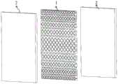
图1为本发明一种空气成像用平板透镜的爆炸图;1 is an exploded view of a flat lens for air imaging of the present invention;
图2为本发明一种空气成像用平板透镜中光波导镜片阵列的主视图;2 is a front view of an optical waveguide lens array in a flat lens for air imaging according to the present invention;
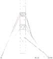
图3为本发明一种空气成像用平板透镜的成像原理图;3 is an imaging principle diagram of a flat lens for air imaging according to the present invention;
图4为一种空气成像系统原理图。Figure 4 is a schematic diagram of an air imaging system.
具体实施方式Detailed ways
下面详细描述本发明的实施例,所述实施例的示例在附图中示出。下面通过参考附图描述的实施例是示例性的,旨在用于解释本发明,而不能理解为对本发明的限制。The following describes in detail the embodiments of the present invention, examples of which are illustrated in the accompanying drawings. The embodiments described below with reference to the accompanying drawings are exemplary, and are intended to explain the present invention and should not be construed as limiting the present invention.
在本发明的描述中,需要理解的是,术语“中心”、“纵向”、“横向”、“长度”、“宽度”、“厚度”、“上”、“下”、“前”、“后”、“左”、“右”、“竖直”、“水平”、“顶”、“底”“内”、“外”等指示的方位或位置关系为基于附图所示的方位或位置关系,仅是为了便于描述本发明和简化描述,而不是指示或暗示所指的装置或元件必须具有特定的方位、以特定的方位构造和操作,因此不能理解为对本发明的限制。In the description of the present invention, it should be understood that the terms "center", "longitudinal", "lateral", "length", "width", "thickness", "upper", "lower", "front", " The orientation or positional relationship indicated by "back", "left", "right", "vertical", "horizontal", "top", "bottom", "inside", "outside", etc. is based on the orientation shown in the drawings or The positional relationship is only for the convenience of describing the present invention and simplifying the description, rather than indicating or implying that the indicated device or element must have a specific orientation, be constructed and operated in a specific orientation, and therefore should not be construed as a limitation of the present invention.
此外,术语“第一”、“第二”仅用于描述目的,而不能理解为指示或暗示相对重要性或者隐含指明所指示的技术特征的数量。由此,限定有“第一”、“第二”的特征可以明示或者隐含地包括至少一个该特征。在本发明的描述中,“多个”的含义是至少两个,例如两个,三个等,除非另有明确具体的限定。In addition, the terms "first" and "second" are only used for descriptive purposes, and should not be construed as indicating or implying relative importance or implying the number of indicated technical features. Thus, a feature delimited with "first", "second" may expressly or implicitly include at least one of that feature. In the description of the present invention, "plurality" means at least two, such as two, three, etc., unless otherwise expressly and specifically defined.
参阅图1、图2为本发明一种空气成像用平板透镜的实施例,一种空气成像用平板透镜,包括光波导阵列结构1和两块平面基板2,光波导结构夹在两块平面基板之间,所述光波导阵列结构包括呈多排多列布置的二面角反射器3,沿列的方向所述二面角反射器的横截面积由光波导阵列结构中心到边缘减小设置。1 and 2 are embodiments of a flat lens for air imaging according to the present invention. A flat lens for air imaging includes an optical waveguide array structure 1 and two planar substrates 2, and the optical waveguide structure is sandwiched between the two planar substrates. In between, the optical waveguide array structure includes
沿列的方向从中间到边缘二面角反射器横截面积减小,形成狭缝的波导结构,让光通过狭缝进行光学成像,球差也更小,成像景深更大,有效提高了成像清晰度,而且这样的设计并不会改变原有平板透镜的尺寸,可以直接替换到原有的空气成像设备上。The cross-sectional area of the dihedral corner reflector decreases from the middle to the edge in the direction of the column, forming a waveguide structure with a slit, allowing the light to pass through the slit for optical imaging, the spherical aberration is also smaller, the imaging depth of field is larger, and the imaging is effectively improved. Moreover, this design does not change the size of the original flat lens, and can be directly replaced on the original air imaging device.
由于空气成像平板透镜使用时都是需要将一个图像在空气中成像,而原光源图像一般成水平放置,这就要求同一排的二面角反射器尺寸要相等,使得原光源图像通过同一排二面角反射器的反射距离相等,可以清楚的成像。Since the air imaging flat lens needs to image an image in the air, and the original light source image is generally placed horizontally, this requires the dihedral corner reflectors in the same row to be equal in size, so that the original light source image passes through the same row of two The reflection distance of the face angle reflector is equal, and the image can be clearly imaged.
而二面角反射器的横截面可以为矩形,但是长边和宽边的差不能太大,满足基本的成像条件,最好二面角反射器的横截面为正方形,两个反射面面积一致,反射光线成像后亮度均匀,并且边长在0.1~4mm之间,如果边长太短会使进光量太少,成像亮度受到极大影响,画面偏暗,而边长太长就不易发生全反射,导致成像失败或者画面模糊。而对于光波导阵列结构的厚度最好在0.5~4mm之间,厚度太低会出现杂光,杂光即未发生反射且通过的光,而厚度太厚会增加摄入光线的损耗。The cross-section of the dihedral corner reflector can be rectangular, but the difference between the long side and the broad side cannot be too large, and the basic imaging conditions are met. , After the reflected light is imaged, the brightness is uniform, and the side length is between 0.1 and 4mm. If the side length is too short, the amount of light entering will be too small, the imaging brightness will be greatly affected, the picture will be dark, and the side length will be too long. reflections, resulting in image failure or blurry images. The thickness of the optical waveguide array structure is preferably between 0.5 and 4 mm. If the thickness is too low, stray light will occur, and stray light is the light that has not been reflected and passed through.
对于不同列的二面角反射器减小设置规则,最好是逐排沿列的方向从中心到边缘等差递减,这样可以最大的保持画面亮度的均匀,获得最佳的成像效果。也可以不按等差递减,而选用按某递减函数的规律递减,比如选择余弦函数0~90度区间的规律递减等等。如图2所示,还可以保持几排尺寸完全相同的二面角反射器组成镜片组,沿列的方向由光波导阵列结构中心到边缘相邻镜片组的二面角反射器面积逐步递减。这需要根据实际所要达到的成像效果和成本预算来控制。For the dihedral corner reflectors in different columns, it is better to decrease the setting rules of the dihedral corner reflectors row by row from the center to the edge in the direction of the column, so that the brightness of the picture can be kept uniform to the greatest extent, and the best imaging effect can be obtained. It is also possible to choose not to decrease according to the arithmetic difference, but to choose to decrease according to the law of a certain decreasing function, such as choosing the law of decreasing the cosine function in the range of 0 to 90 degrees, and so on. As shown in Figure 2, several rows of dihedral corner reflectors with the same size can also be maintained to form a lens group, and the dihedral corner reflector areas of adjacent lens groups from the center of the optical waveguide array structure to the edge in the direction of the column gradually decrease. This needs to be controlled according to the actual imaging effect to be achieved and the cost budget.
为了保证同一排二面角反射器之间的间距相等,面积不同的两排二面角反射器之间留有调整间隙4,将相邻的两排二面角反射器隔开一定距离作为调整。In order to ensure the same distance between the dihedral corner reflectors in the same row, an adjustment gap 4 is left between the two rows of dihedral corner reflectors with different areas, and the two adjacent rows of dihedral corner reflectors are separated by a certain distance as adjustment .
光波导阵列结构可以先制作二面角反射器,然后通过光敏胶粘接成形,再与两块平面基板胶合压注成整体,也可以通过微纳加工技术或光刻技术在基板上直接刻蚀出二面角反射器。平面基板采用高透光率光学基板,主要起固定和保护的作用。The optical waveguide array structure can be made of a dihedral corner reflector first, then bonded and formed by photosensitive adhesive, and then glued and pressure-injected with two flat substrates. It can also be directly etched on the substrate by micro-nano processing technology or photolithography technology. Out of the dihedral corner reflector. The plane substrate adopts a high transmittance optical substrate, which mainly plays the role of fixing and protection.
如图3所示,为本发明的成像原理图,实线为改进后的成像图,虚线为改进前的成像图,改进前点光源O通过光波导的成像弥散斑直径为虚线的B1B2,而本发明方案的成像弥散斑直径为实线A1A2,因B1B2比A1A2大,因此本发明专利弥散斑较小,像差较小,优于之前的专利设计。As shown in FIG. 3, it is the imaging principle diagram of the present invention, the solid line is the imaging diagram after improvement, the dotted line is the imaging diagram before improvement, the imaging dispersion spot diameter of the point light source O through the optical waveguide before the improvement is B1B2 of the dotted line, and The diameter of the imaging diffuse spot of the solution of the present invention is the solid line A1A2. Because B1B2 is larger than A1A2, the diffused spot of the patent of the present invention is smaller and the aberration is smaller, which is better than the previous patent design.
如图4所示,一种空气成像系统,包括光源5和平板透镜6,所述平板透镜为上述任意一种空气成像用平板透镜,光源5发出的光线通过平板透镜6在空气中成像7。As shown in FIG. 4 , an air imaging system includes a
以上所述仅为本发明的具体实施例,但本发明的技术特征并不局限于此,任何本领域的技术人员在本发明的领域内,所作的变化或修饰皆涵盖在本发明的专利范围之中。The above are only specific embodiments of the present invention, but the technical features of the present invention are not limited thereto. Any changes or modifications made by those skilled in the art in the field of the present invention are all covered by the patent scope of the present invention. among.
Claims (11)
Applications Claiming Priority (2)
| Application Number | Priority Date | Filing Date | Title |
|---|---|---|---|
| CN2019109420398 | 2019-09-30 | ||
| CN201910942039 | 2019-09-30 |
Publications (1)
| Publication Number | Publication Date |
|---|---|
| CN110687625Atrue CN110687625A (en) | 2020-01-14 |
Family
ID=69112150
Family Applications (1)
| Application Number | Title | Priority Date | Filing Date |
|---|---|---|---|
| CN201910958807.9APendingCN110687625A (en) | 2019-09-30 | 2019-10-10 | Flat lens for air imaging and air imaging system |
Country Status (1)
| Country | Link |
|---|---|
| CN (1) | CN110687625A (en) |
Cited By (3)
| Publication number | Priority date | Publication date | Assignee | Title |
|---|---|---|---|---|
| CN111366338A (en)* | 2020-04-24 | 2020-07-03 | 华中科技大学 | An imaging quality detection device and method for a virtual imaging optical system |
| CN112946914A (en)* | 2021-02-23 | 2021-06-11 | 荆门市探梦科技有限公司 | Transmission type geometric holographic screen with field angle and application thereof |
| CN114185173A (en)* | 2021-12-13 | 2022-03-15 | 深圳前海智云谷科技有限公司 | High-brightness high-contrast medium-free air suspension display device |
Citations (5)
| Publication number | Priority date | Publication date | Assignee | Title |
|---|---|---|---|---|
| CN1217064A (en)* | 1996-04-30 | 1999-05-19 | 明尼苏达矿业和制造公司 | Molds for producing shiny cube-corner retroreflective sheeting |
| JP2008242208A (en)* | 2007-03-28 | 2008-10-09 | Seiko Epson Corp | Image display device and projector |
| US20110285965A1 (en)* | 2010-05-21 | 2011-11-24 | Stanley Electric Co., Ltd. | Display device |
| CN104160304A (en)* | 2012-02-29 | 2014-11-19 | 日东电工株式会社 | Dihedral corner reflector array |
| CN211293324U (en)* | 2019-09-30 | 2020-08-18 | 浙江棱镜全息科技有限公司 | Flat lens for air imaging and air imaging system |
- 2019
- 2019-10-10CNCN201910958807.9Apatent/CN110687625A/enactivePending
Patent Citations (5)
| Publication number | Priority date | Publication date | Assignee | Title |
|---|---|---|---|---|
| CN1217064A (en)* | 1996-04-30 | 1999-05-19 | 明尼苏达矿业和制造公司 | Molds for producing shiny cube-corner retroreflective sheeting |
| JP2008242208A (en)* | 2007-03-28 | 2008-10-09 | Seiko Epson Corp | Image display device and projector |
| US20110285965A1 (en)* | 2010-05-21 | 2011-11-24 | Stanley Electric Co., Ltd. | Display device |
| CN104160304A (en)* | 2012-02-29 | 2014-11-19 | 日东电工株式会社 | Dihedral corner reflector array |
| CN211293324U (en)* | 2019-09-30 | 2020-08-18 | 浙江棱镜全息科技有限公司 | Flat lens for air imaging and air imaging system |
Cited By (5)
| Publication number | Priority date | Publication date | Assignee | Title |
|---|---|---|---|---|
| CN111366338A (en)* | 2020-04-24 | 2020-07-03 | 华中科技大学 | An imaging quality detection device and method for a virtual imaging optical system |
| CN112946914A (en)* | 2021-02-23 | 2021-06-11 | 荆门市探梦科技有限公司 | Transmission type geometric holographic screen with field angle and application thereof |
| CN112946914B (en)* | 2021-02-23 | 2024-04-02 | 荆门市探梦科技有限公司 | Transmission type geometric holographic screen with opening angle and its application |
| CN114185173A (en)* | 2021-12-13 | 2022-03-15 | 深圳前海智云谷科技有限公司 | High-brightness high-contrast medium-free air suspension display device |
| CN114185173B (en)* | 2021-12-13 | 2024-02-23 | 深圳前海智云谷科技有限公司 | Medium-free air suspension display device with high brightness and high contrast |
Similar Documents
| Publication | Publication Date | Title |
|---|---|---|
| TWI381193B (en) | Optical sheet and display device including the same | |
| US10067369B2 (en) | Display apparatus with a prism module including a corner prism set disposed on a corner region | |
| US6456436B2 (en) | Optical device | |
| CN211061779U (en) | Image reproducing zoom optical device using flat lens and air imaging system | |
| US20210165139A1 (en) | Prism film, backlight module and display device | |
| CN113009692B (en) | Near-eye light field display device | |
| CN110687625A (en) | Flat lens for air imaging and air imaging system | |
| CN110794495A (en) | Flat lens for air imaging and air imaging system | |
| US20180321477A1 (en) | Light-emitting unit with fresnel optical system and light-emitting apparatus and display system using same | |
| JP6410094B2 (en) | Head-up display | |
| WO2019179167A1 (en) | Curved screen and method of arranging microstructure therein, and projection system | |
| WO2023125103A1 (en) | Micro-optical lens, preparation method therefor, and display system | |
| CN110208902B (en) | Flat lens for imaging | |
| CN114859450A (en) | Fresnel lens group and virtual reality device | |
| JP5533310B2 (en) | Light guide plate, surface light source device and display device | |
| CN203786454U (en) | Lighting system and projection device | |
| CN101363926B (en) | LCD device and prismatic lens thereof | |
| CN110208896B (en) | Novel optical waveguide and screen using same | |
| CN210803764U (en) | Flat lens for air imaging and air imaging system | |
| CN211293324U (en) | Flat lens for air imaging and air imaging system | |
| US11966049B2 (en) | Pupil tracking near-eye display | |
| CN118311699A (en) | Fresnel lens, optical machine and projector | |
| CN110764256B (en) | Large-depth-of-field flat lens for air imaging and air imaging system | |
| JP6008241B2 (en) | Surface light source device and display device | |
| CN211905753U (en) | Optical lens |
Legal Events
| Date | Code | Title | Description |
|---|---|---|---|
| PB01 | Publication | ||
| PB01 | Publication | ||
| SE01 | Entry into force of request for substantive examination | ||
| SE01 | Entry into force of request for substantive examination | ||
| RJ01 | Rejection of invention patent application after publication | Application publication date:20200114 | |
| RJ01 | Rejection of invention patent application after publication |