CN110685512A - Cable lock with double unlocking mechanism - Google Patents
Cable lock with double unlocking mechanismDownload PDFInfo
- Publication number
- CN110685512A CN110685512ACN201910548583.4ACN201910548583ACN110685512ACN 110685512 ACN110685512 ACN 110685512ACN 201910548583 ACN201910548583 ACN 201910548583ACN 110685512 ACN110685512 ACN 110685512A
- Authority
- CN
- China
- Prior art keywords
- shaft
- lock
- lock body
- clutch
- cable
- Prior art date
- Legal status (The legal status is an assumption and is not a legal conclusion. Google has not performed a legal analysis and makes no representation as to the accuracy of the status listed.)
- Granted
Links
Images


Classifications
- E—FIXED CONSTRUCTIONS
- E05—LOCKS; KEYS; WINDOW OR DOOR FITTINGS; SAFES
- E05B—LOCKS; ACCESSORIES THEREFOR; HANDCUFFS
- E05B37/00—Permutation or combination locks; Puzzle locks
- E05B37/0031—Locks with both permutation and key actuation
- E05B37/0034—Locks with both permutation and key actuation actuated by either
- E—FIXED CONSTRUCTIONS
- E05—LOCKS; KEYS; WINDOW OR DOOR FITTINGS; SAFES
- E05B—LOCKS; ACCESSORIES THEREFOR; HANDCUFFS
- E05B67/00—Padlocks; Details thereof
- E05B67/003—Chain, wire or cable locks
- E—FIXED CONSTRUCTIONS
- E05—LOCKS; KEYS; WINDOW OR DOOR FITTINGS; SAFES
- E05B—LOCKS; ACCESSORIES THEREFOR; HANDCUFFS
- E05B15/00—Other details of locks; Parts for engagement by bolts of fastening devices
- E—FIXED CONSTRUCTIONS
- E05—LOCKS; KEYS; WINDOW OR DOOR FITTINGS; SAFES
- E05B—LOCKS; ACCESSORIES THEREFOR; HANDCUFFS
- E05B37/00—Permutation or combination locks; Puzzle locks
- E05B37/02—Permutation or combination locks; Puzzle locks with tumbler discs or rings arranged on a single axis, each disc being adjustable independently of the others
- E05B37/025—Permutation or combination locks; Puzzle locks with tumbler discs or rings arranged on a single axis, each disc being adjustable independently of the others in padlocks
- E—FIXED CONSTRUCTIONS
- E05—LOCKS; KEYS; WINDOW OR DOOR FITTINGS; SAFES
- E05B—LOCKS; ACCESSORIES THEREFOR; HANDCUFFS
- E05B67/00—Padlocks; Details thereof
Landscapes
- Lock And Its Accessories (AREA)
Abstract
Description
Translated fromChinese相关申请的交叉引用CROSS-REFERENCE TO RELATED APPLICATIONS
本申请要求2018年7月5日提交的美国临时专利申请号62/694,244的优先权权益,其在此通过引用全部并入本文。This application claims the benefit of priority from US Provisional Patent Application No. 62/694,244, filed July 5, 2018, which is hereby incorporated by reference in its entirety.
技术领域technical field
本发明总体上涉及一种挂锁,更具体地,涉及一种具有双重解锁机构的缆锁。The present invention generally relates to a padlock, and more particularly, to a cable lock with a dual unlocking mechanism.
背景技术Background technique
缆锁是具有柔性缆而不是钩环的锁,该柔性缆布置为穿过开口以防止物体或结构未经授权的使用。在具有双重解锁机构的锁中,锁可以通过组合锁定系统或通过钥匙超驰系统打开。在具有钩环的锁中,锁体必须在锁体中具有足够长的通道以接收钩环的跟部。如果趾部被布置为上下移动一段距离以锁定并且打开锁,则必须允许跟部移动相同的距离。通过柔性缆,缆的一端部可以固定地连接到锁体上。不需要在锁体中设置长通道来接收缆。A cable lock is a lock that has a flexible cable, rather than a shackle, that is routed through an opening to prevent unauthorized use of an object or structure. In locks with a double unlocking mechanism, the lock can be opened by a combination locking system or by a key override system. In a lock with a shackle, the lock body must have a channel in the lock body long enough to receive the heel of the shackle. If the toe is arranged to move up and down a distance to lock and unlock the lock, the heel must be allowed to move the same distance. By means of a flexible cable, one end of the cable can be fixedly connected to the lock body. There is no need for a long channel in the lock body to receive the cable.
发明内容SUMMARY OF THE INVENTION
本发明涉及一种具有柔性缆而不是钩环的缆锁。该锁具有可相对于锁体移动的轴,使得轴的顶部可以移出锁体以打开锁。该锁具有组合解锁系统和钥匙超驰系统。因此,锁可以通过开锁组合或通过正确的钥匙解锁。缆的第一端部被固定地连接到锁体上,并且第二端部可移动地与靠近轴顶部的轴槽接合。当锁在锁定模式下操作时,轴槽位于锁体的内部,从而防止缆的第二端部从轴槽移除。当锁在打开模式下操作时,轴槽位于锁体的外部,从而允许缆的第二端部从轴槽移除。The present invention relates to a cable lock with a flexible cable instead of a shackle. The lock has a shaft that is movable relative to the lock body so that the top of the shaft can move out of the lock body to open the lock. The lock has a combined unlocking system and a key override system. Therefore, the lock can be unlocked by a combination of unlocking or by the correct key. The first end of the cable is fixedly attached to the lock body and the second end is movably engaged with the shaft slot near the top of the shaft. When the lock is operating in the locked mode, the shaft slot is located inside the lock body, preventing the second end of the cable from being removed from the shaft slot. When the lock is operating in the open mode, the shaft slot is located on the outside of the lock body, allowing the second end of the cable to be removed from the shaft slot.
因此,本发明的一个方面提供一种在锁定模式和打开模式下可操作的锁。该锁的一个实施例包括:Accordingly, one aspect of the present invention provides a lock operable in a locked mode and an open mode. One embodiment of the lock includes:
缆,该缆具有第一缆端部和第二缆端部;a cable having a first cable end and a second cable end;
锁体,该锁体布置为固定第一缆端部,该锁体具有接收第二缆端部的切口;a lock body arranged to secure the first cable end, the lock body having a cutout for receiving the second cable end;
轴,当锁在锁定模式下操作时轴位于第一轴位置,并且当锁在打开模式下操作时轴位于第二轴位置,该轴具有布置为固定缆的第二缆端部的轴槽;以及a shaft in a first shaft position when the lock is operated in a locked mode and in a second shaft position when the lock is operated in an open mode, the shaft having a shaft slot arranged to secure a second cable end of the cable; as well as
多个离合器,该多个离合器形成离合器组,该离合器组布置为控制轴在相对于锁体的运动方向上的运动,其中a plurality of clutches forming a clutch pack arranged to control movement of the shaft in a direction of movement relative to the lock body, wherein
当轴位于第一轴位置时,轴槽位于锁体的内部,从而防止第二缆端部从锁体释放,以及When the shaft is in the first shaft position, the shaft groove is located inside the lock body, thereby preventing the second cable end from being released from the lock body, and
当轴位于第二轴位置时,轴槽位于锁体的外部,从而允许第二缆端部从轴槽移除。When the shaft is in the second shaft position, the shaft slot is external to the lock body, allowing the second cable end to be removed from the shaft slot.
根据本发明的一个实施例,该锁还包括:According to one embodiment of the present invention, the lock further includes:
第一解锁机构,该第一解锁结构可操作地联接到离合器组,以及a first unlocking mechanism operably coupled to the clutch pack, and
第二解锁机构,该第二解锁结构可操作地联接到离合器组,第一解锁机构包括可与离合器组接合的多个拨盘,其中当拨盘被布置为匹配开锁组合时,离合器组被布置为允许轴在相对于离合器组的运动方向上从第一轴位置移动到第二轴位置,并且其中第二解锁机构包括闩锁板,A second unlocking mechanism operatively coupled to the clutch pack, the first unlocking mechanism comprising a plurality of dials engageable with the clutch pack, wherein the clutch pack is arranged when the dials are arranged to match the unlocking combination To allow movement of the shaft from the first shaft position to the second shaft position in the direction of motion relative to the clutch pack, and wherein the second unlocking mechanism includes a latch plate,
闩锁板能够位于第一板位置以防止离合器组在相对于锁体的运动方向上移动,并且the latch plate is positionable in the first plate position to prevent movement of the clutch pack in the direction of motion relative to the lock body, and
闩锁板能够位于第二板位置以允许离合器组与轴一起在相对于锁体的运动方向上移动,从而使轴从第一轴位置移动到第二轴位置,其中第二解锁机构还包括可通过钥匙操作的圆柱状物,该圆柱状物布置为使闩锁从第一板位置移动到第二板位置。The latch plate can be located in a second plate position to allow the clutch pack to move with the shaft in a direction of movement relative to the lock body to move the shaft from the first shaft position to the second shaft position, wherein the second unlocking mechanism further includes a A key operated cylinder arranged to move the latch from the first plate position to the second plate position.
根据本发明的一个实施例,每个拨盘与离合器中的不同一个相关联,并且每个离合器都包括延伸翅片,并且其中每个拨盘都具有多个拨盘槽,每个拨盘槽都定尺寸为接收相关联离合器的用于一起旋转的延伸翅片,其中轴还包括多个突起,每个突起与离合器中的一个相关联,并且每个离合器都具有内环,其中内环上形成有开口间隙,并且其中According to one embodiment of the invention, each dial is associated with a different one of the clutches, and each clutch includes extending fins, and wherein each dial has a plurality of dial grooves, each dial groove Both are dimensioned to receive extension fins for co-rotation of the associated clutch, wherein the shaft further includes a plurality of projections, each projection being associated with one of the clutches, and each clutch has an inner ring with an inner ring on the inner ring is formed with an opening gap, and wherein
当锁在锁定模式下操作时,离合器中的至少一个的内环被布置为防止轴在相对于离合器组的运动方向上移动以使轴槽移出锁体,以及an inner ring of at least one of the clutches is arranged to prevent movement of the shaft in a direction of movement relative to the clutch pack to move the shaft slot out of the lock body when the lock is operating in a locked mode, and
当拨盘被布置为匹配开锁组合时,在每个离合器的内环上的开口间隙与轴的相关联突起对齐,从而允许轴在相对于离合器组的运动方向上从第一轴位置移动到第二轴位置。When the dial is arranged to mate with the unlocking combination, the open gap on the inner ring of each clutch aligns with the associated protrusion of the shaft, thereby allowing the shaft to move in the direction of motion relative to the clutch pack from the first shaft position to the second Two-axis position.
根据本发明的一个实施例,闩锁板包括销槽,锁还包括:According to one embodiment of the invention, the latch plate includes a pin slot, and the lock further includes:
凸轮,该凸轮具有凸轮槽和凸轮销,该凸轮销可与销槽移动地接合,以及a cam having a cam slot and a cam pin movably engaged with the pin slot, and
圆柱状物,该圆柱状物具有钥匙槽和叉,该钥匙槽定尺寸为接收钥匙,该叉与凸轮槽接合以用于一起旋转,其中当钥匙被插入钥匙槽以使圆柱状物与凸轮一起转动时,使闩锁板从第一板位置移动到第二板位置。A cylinder having a key slot and a fork sized to receive a key, the fork engaging the cam slot for co-rotation, wherein when the key is inserted into the key slot to engage the cylinder with the cam When rotated, the latch plate is moved from the first plate position to the second plate position.
根据本发明的一个实施例,锁体具有第一锁体侧部和相对的第二锁体侧部,第一锁体侧部具有接收第一缆端部的固定端部槽和接收第二缆端部的切口,其中每个离合器的内环具有上侧部和相对的下侧部,其中上侧部比第二锁体侧部更靠近第一锁体侧部,其中当锁在锁定模式下操作时,轴位于第一轴位置,并且轴的每个突起都位于相关联离合器的内环的下侧部附近,并且当通过第一解锁机构使锁从锁定模式改变为打开模式时,轴位于第二轴位置,并且轴的每个突起都位于相关联离合器的内环的上侧部附近,从而允许轴相对于锁体旋转,使得轴的每个突起与相关联离合器的开口间隙间隔开,同时轴的每个突起都位于相关联离合器的上侧部的附近,其中当轴被推向锁体的第二锁体侧部时,使离合器组从拨盘脱离,从而允许拨盘独立于离合器旋转,以设置不同的开锁组合。According to one embodiment of the present invention, the lock body has a first lock body side portion and an opposite second lock body side portion, the first lock body side portion having a fixed end slot for receiving the end of the first cable and receiving the second cable Cutouts at the ends, wherein the inner ring of each clutch has an upper side and an opposite lower side, wherein the upper side is closer to the first lock body side than the second lock body side, wherein when the lock is in the locked mode In operation, the shaft is in the first shaft position and each protrusion of the shaft is located adjacent the underside of the inner ring of the associated clutch, and when the lock is changed from the locked mode to the open mode by the first unlocking mechanism, the shaft is in a second shaft position and each projection of the shaft is located near the upper side of the inner ring of the associated clutch, allowing the shaft to rotate relative to the lock body such that each projection of the shaft is spaced from the opening gap of the associated clutch, At the same time each protrusion of the shaft is located near the upper side of the associated clutch, wherein when the shaft is pushed towards the second lock body side of the lock body, the clutch pack is disengaged from the dial, allowing the dial to be independent of the clutch Rotate to set different unlock combinations.
附图说明Description of drawings
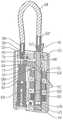
图1A是处于锁定模式的本发明的缆锁的剖视图;1A is a cross-sectional view of the cable lock of the present invention in a locked mode;
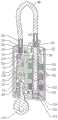
图1B是沿图1A的标记线截取的缆锁的剖视图;FIG. 1B is a cross-sectional view of the cable lock taken along the line marked in FIG. 1A ;
图2是盖子的透视图;Figure 2 is a perspective view of the cover;
图3A是锁体一半的透视图;3A is a perspective view of one half of the lock body;
图3B是相同的锁体一半的另一透视图;Figure 3B is another perspective view of the same lock body half;
图4A是锁体的另一半的透视图;4A is a perspective view of the other half of the lock body;
图4B是图4A的锁体一半的另一透视图;Figure 4B is another perspective view of one half of the lock body of Figure 4A;
图5是缆端部的透视图;Figure 5 is a perspective view of a cable end;
图6是闩锁板的透视图;Figure 6 is a perspective view of the latch plate;
图7是凸轮的透视图;Figure 7 is a perspective view of a cam;
图8是圆柱状物的透视图;Figure 8 is a perspective view of a cylinder;
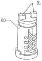
图9是轴的透视图;Figure 9 is a perspective view of the shaft;
图10是离合器的透视图;Figure 10 is a perspective view of the clutch;
图11是拨盘的透视图;Figure 11 is a perspective view of the dial;
图12是间隔环的透视图;Figure 12 is a perspective view of the spacer ring;
图13A是处于通过开锁组合解锁的打开模式的缆锁的剖视图;13A is a cross-sectional view of a cable lock in an open mode unlocked by an unlocking combination;
图13B是沿图13A的标记线截取的缆锁的剖视图;Figure 13B is a cross-sectional view of the cable lock taken along the marked line of Figure 13A;
图14A是处于通过钥匙超驰系统解锁的打开模式的缆锁的剖视图;14A is a cross-sectional view of a cable lock in an open mode unlocked by a key override system;
图14B是沿图14A的标记线截取的缆锁的剖视图;Figure 14B is a cross-sectional view of the cable lock taken along the marked line of Figure 14A;
图15A是处于复位模式的缆锁的剖视图;15A is a cross-sectional view of the cable lock in a reset mode;
图15B是沿图15A的标记线截取的缆锁的剖视图;Figure 15B is a cross-sectional view of the cable lock taken along the marked line of Figure 15A;
图16是处于锁定模式的缆锁的另一剖视图;Figure 16 is another cross-sectional view of the cable lock in a locked mode;
图17是处于通过开锁组合解锁的打开模式的缆锁的另一剖视图;17 is another cross-sectional view of the cable lock in an open mode unlocked by the unlocking combination;
图18是处于通过钥匙超驰系统解锁的打开模式的缆锁的另一剖视图;18 is another cross-sectional view of the cable lock in an open mode unlocked by the key override system;
图19是处于复位模式的缆锁的另一剖视图。19 is another cross-sectional view of the cable lock in a reset mode.
具体实施方式Detailed ways
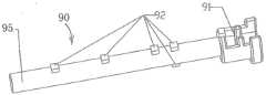
本发明提供了一种具有双重解锁机构的锁10:组合解锁系统和钥匙超驰机构。因此,锁10可以通过开锁组合或通过正确的钥匙打开。如图1A-19所示,锁10具有由与一个或多个安全销130和盖子20保持在一起的两个半部30、40制成的锁体。锁体30/40具有定尺寸为接收一组离合器100和轴90的锁体通道。锁体30/40还具有接收多个拨盘110的多个锁体槽37/47,每个拨盘110都与离合器100相关联。轴90具有与一组离合器100可移动地接合的轴体95。轴90在轴体95的顶部具有缆颈部槽91。锁10包括缆48,缆48具有固定在锁体30/40中的第一缆端部50和具有与缆颈部槽91可拆卸地接合的缆颈部51'的第二缆端部50'。锁体还具有与锁体通道连通的轴突出切口33/43,该轴突出切口33当锁10在锁定模式下操作时定尺寸为接收缆颈部槽91。每个离合器100具有位于离合器外表面上的延伸翅片103和具有形成在其上的开口间隙102的内环101。每个拨盘110具有多个定尺寸为接收延伸翅片103的拨盘槽111,使得当每个拨盘110转动时,相关联的离合器100也转动。轴90的轴体95具有多个突起92,每个突起92与离合器100相关联。每个突起92当锁10在锁定模式下操作时位于相关联的离合器100的内环101下方。内环101上的开口间隙102定尺寸为允许突起92穿过以通过组合解锁系统打开锁。The present invention provides a
组合解锁系统通过拨盘110控制,使得当拨盘110转动以匹配预设的开锁组合时,每个离合器100的开口间隙102与轴90的相关突起92对齐,从而允许轴90相对于离合器110向上移动,使得缆颈部槽91移出轴突出切口43。缆48的缆颈部51'然后能够从缆颈部槽91释放以打开锁10。The combination unlocking system is controlled by the
锁10具有可在第一闩锁位置和第二闩锁位置之间移动的闩锁板60。闩锁板60具有阻挡表面61。当闩锁板60位于第一闩锁位置时,闩锁板60的阻挡表面61与最上面的离合器100的上表面接触,从而防止一组离合器100相对于锁体向上移动。当闩锁板60位于第二闩锁位置时,阻挡表面61与最上面的离合器100间隔开,从而允许一组离合器100与轴90一起向上移动。钥匙超驰系统由圆柱状物80和凸轮70控制。凸轮70具有设置在凸轮70的下表面上的凸轮槽72和从凸轮70的上表面延伸的延伸销71。圆柱状物80具有布置为与凸轮槽72接合以用于一起旋转的延伸叉81。闩锁板60还具有定尺寸为接收凸轮70的延伸销71的销接收槽62。当正确的钥匙140被插入圆柱状物80中来转动圆柱状物80时,凸轮70也以相同的方式转动。当凸轮70转动时,凸轮70的延伸销71使闩锁板60远离一组离合器100的顶表面移动。如此,轴90可以与全部一组离合器100一起向上拉动,使得轴90的缆颈部槽91移出锁体30/40的轴突出切口33/43。缆48的缆颈部51'然后可以从缆颈部槽91释放以用于锁定开口。The
锁定模式(图1A-12和图16)Locked Mode (Figures 1A-12 and 16)
当锁10在锁定模式下操作时,轴90的缆颈部槽91位于锁体30/40的轴突出切口33/43中,从而防止缆48的缆端部50'从缆颈部槽91释放。When the
在锁定模式中,拨盘110的设置不同于开锁组合。至少一个离合器100的开口间隙102不与轴90的相关联突起92对齐,并且突起92位于至少一个离合器100的内环101的正下方。至少一个离合器100的内环101防止轴90相对于一组离合器100向上移动。当轴90的缆颈部槽91保持在锁体30/40的轴突出切口33/43中时,缆48的缆端部50'不能从缆颈部槽91释放。同时,闩锁板60位于第一闩锁位置,从而防止一组离合器100和轴90向上移动。In the locked mode, the setting of the
此外,当钥匙140不存在时,圆柱状物80和凸轮70不能转动以将闩锁板60从第一闩锁位置移动到第二闩锁位置。Furthermore, when the key 140 is not present, the
通过组合解锁(图13A-13B和图17)Unlock by combination (Figures 13A-13B and Figure 17)
当锁10在锁定模式下操作时,至少一个离合器100的开口间隙102与轴90的相关联突起92不对齐,并且突起92位于至少一个离合器100的内环101的正下方。内环101用作防止相关联的突起92移动通过的障碍。因此,轴90不能相对于离合器100移动。同时,每个离合器100的延伸翅片103位于相关联拨盘110的一个拨盘槽111中,从而使得离合器100与相关联的拨盘110一起旋转。当转动拨盘110来匹配开锁组合时,每个离合器100的开口间隙102与轴90的突起92对齐。离合器100的内环101不再是轴90的相关联突起92的障碍。如此,轴90可以相对于离合器100向上拉,使得缆颈部槽91移出锁体30/40的轴突出切口33/43(例如,参见图13A)。然后可以将缆端部50'侧向移动以从轴90的缆颈部槽91释放缆48的缆颈部51'以打开锁10。应当注意的是,当锁10通过组合解锁系统解锁时,闩锁板60位于第一板位置,并且阻挡表面61防止离合器100相对于锁体30/40向上移动。轴90是锁10中具有相对于锁体30/40的垂直运动的唯一部件。When the
复位组合(图15A-15B和图19)Reset Combination (Figures 15A-15B and Figure 19)
当轴90被向上拉以通过组合解锁系统来解锁锁10时,轴90的每个突起92位于相关联离合器100的内环101上的开口间隙102上方。轴90可以相对于锁体30/40自由旋转。使用者可以将轴90转过预定角度(例如,轴90沿顺时针方向旋转180度)并且向下推动轴90。在转动轴90之后,突起92远离内环101的开口间隙102移动。当轴90向下推时,它向下推动离合器100,从而使离合器100的延伸翅片103脱离拨盘110的拨盘槽111。拨盘110可以独立于离合器100旋转以设定不同的开锁组合。当轴90被释放时,间隔环120下方的弹簧被布置为将间隔环120和离合器100向上推到他们的初始位置,使得离合器100的每个延伸翅片103再次与相关联的拨盘110的拨盘槽111接合。间隔环120具有外部突起121,在复位突起槽34/44中使得当锁10被钥匙超驰系统解锁时,防止间隔环120掉出。When the
通过钥匙解锁(图14A-14B和图18)Unlock by key (Figure 14A-14B and Figure 18)
根据本发明的一个实施例,圆柱状物80的延伸叉81总是与凸轮70的凸轮槽72接合。当正确的钥匙140被插入圆柱状物80时,圆柱状物80可以与凸轮70一起相对于锁体30/40转动。当凸轮70转动时,位于闩锁板60的销接收槽62中的凸轮70的延伸销71使闩锁板60远离一组离合器100移动。闩锁板60的阻挡表面61远离最上面的离合器100的上表面移动。全部的一组离合器100可以与轴90一起向上拉动,使得轴90的缆颈部槽91移出锁体30/40。缆48的缆端部50'可以从轴90的缆颈部槽91中释放。然而,当拨盘110保持在锁体30/40的锁体槽37/47中时,拨盘110仍然与一组离合器100接合,从而防止拨盘110相对于离合器100转动。因此,当锁10通过钥匙超驰机构解锁时,无法改变开锁组合。According to one embodiment of the present invention, the extending
其他特征Other features
锁体30/40具有固定缆端部槽32/42,该固定缆端部槽32/42被布置为接收缆48的第一缆端部50的颈部51。第一缆端部50始终固定到锁体30/40。The
根据本发明的一个实施例,锁体半部30具有安全销孔31,并且锁体半部40具有安全销孔41。锁10具有含有两个销孔21的盖子20,每个销孔21与安全销孔31和41中的一个对齐以接收安全销130。盖子20和锁体30/40一体的结合在一起。According to one embodiment of the present invention, the
根据本发明,第一缆端部50和第二缆端部50'是相同的。然而,缆端部50可以不同于缆端部50'。此外,每个离合器100仅具有一个延伸翅片103,该延伸翅片103布置为与拨盘槽111中的一个接合,使得离合器100与相关联的拨盘110一起旋转。然而,每个离合器100都可以具有两个或更多个延伸翅片103。According to the invention, the
因此,尽管已经关于本发明的一个或多个实施例描述了本发明,但是本领域技术人员将要理解的是,在不脱离本发明的范围的情况下,可以在其形式和细节上进行上述和各种其他改变、省略和偏离。Thus, while the present invention has been described with respect to one or more embodiments of the invention, it will be understood by those skilled in the art that the foregoing and details may be made in form and detail without departing from the scope of the invention. Various other changes, omissions and departures.
Claims (5)
Applications Claiming Priority (4)
| Application Number | Priority Date | Filing Date | Title |
|---|---|---|---|
| US201862694244P | 2018-07-05 | 2018-07-05 | |
| US62/694,244 | 2018-07-05 | ||
| US16/423,508 | 2019-05-28 | ||
| US16/423,508US11391063B2 (en) | 2018-07-05 | 2019-05-28 | Cable lock having dual unlocking mechanism |
Publications (2)
| Publication Number | Publication Date |
|---|---|
| CN110685512Atrue CN110685512A (en) | 2020-01-14 |
| CN110685512B CN110685512B (en) | 2021-04-16 |
Family
ID=69101894
Family Applications (1)
| Application Number | Title | Priority Date | Filing Date |
|---|---|---|---|
| CN201910548583.4AActiveCN110685512B (en) | 2018-07-05 | 2019-06-24 | Cable lock with double unlocking mechanism |
Country Status (2)
| Country | Link |
|---|---|
| US (1) | US11391063B2 (en) |
| CN (1) | CN110685512B (en) |
Cited By (1)
| Publication number | Priority date | Publication date | Assignee | Title |
|---|---|---|---|---|
| WO2023130669A1 (en)* | 2022-01-05 | 2023-07-13 | The Sun Lock Company Limited | Object shaped combination padlock |
Families Citing this family (8)
| Publication number | Priority date | Publication date | Assignee | Title |
|---|---|---|---|---|
| USD864695S1 (en)* | 2017-10-27 | 2019-10-29 | The Sun Lock Company Ltd. | Padlock |
| US10890013B2 (en)* | 2017-11-22 | 2021-01-12 | The Sunlock Company, Ltd. | Cable lock with dual unlocking mechanism |
| EP3803723A4 (en) | 2018-06-01 | 2022-03-09 | Stress Engineering Services, Inc. | SYSTEMS AND PROCEDURES FOR MONITORING, TRACKING AND TRACEBACK OF LOGISTICS |
| US12018516B2 (en) | 2021-06-30 | 2024-06-25 | Delta Cycle Corporation | Electronic lock |
| US12024924B2 (en)* | 2021-07-01 | 2024-07-02 | Delta Cycle Corporation | Electronic lock |
| US12060733B2 (en) | 2021-08-16 | 2024-08-13 | Delta Cycle Corporation | Bicycle cable lock |
| US11773626B2 (en) | 2022-02-15 | 2023-10-03 | Stress Engineering Services, Inc. | Systems and methods for facilitating logistics |
| TW202500850A (en)* | 2023-06-14 | 2025-01-01 | 富爾億實業有限公司 | Lock and locking method |
Citations (9)
| Publication number | Priority date | Publication date | Assignee | Title |
|---|---|---|---|---|
| US972171A (en)* | 1909-12-07 | 1910-10-11 | Louis H Dupont | Combination-padlock. |
| US6363758B1 (en)* | 2000-04-11 | 2002-04-02 | Chong-Kuan Ling | Ergonomically manipulated cable combination lock with lay-out operations in angular relationship |
| US6997023B1 (en)* | 2004-10-20 | 2006-02-14 | Glox Industry Co., Ltd. | Combined combination lock and padlock |
| US20060075793A1 (en)* | 2004-10-13 | 2006-04-13 | Yu Chun T | Cable lock |
| US20080016922A1 (en)* | 2004-01-20 | 2008-01-24 | Chun Te Yu | Padlock |
| DE202006020233U1 (en)* | 2006-07-10 | 2008-03-20 | Magnum Industries Ltd. | combination lock |
| CN101555740A (en)* | 2009-05-06 | 2009-10-14 | 许国清 | Coded lock with key on cable wire |
| CN202970159U (en)* | 2011-11-15 | 2013-06-05 | 黎国豪 | Coded lock with auxiliary opening mechanism |
| CN105840009A (en)* | 2015-01-30 | 2016-08-10 | 特新实业有限公司 | Puzzle padlock with double locking and advanced anti-prying mechanism |
Family Cites Families (12)
| Publication number | Priority date | Publication date | Assignee | Title |
|---|---|---|---|---|
| US5156028A (en)* | 1991-04-08 | 1992-10-20 | Jiang Jy Chang | Padlock having a cable shackle and a locking means based on combination of numerals |
| TWM247656U (en)* | 2003-08-26 | 2004-10-21 | Sinox Co Ltd | Lock device |
| TW200835838A (en)* | 2007-02-16 | 2008-09-01 | Chun-Te Yu | Dual-locking device |
| TWM331025U (en)* | 2007-11-09 | 2008-04-21 | jian-yong Huang | Number padlock with dual combination number |
| TW201043768A (en)* | 2009-06-06 | 2010-12-16 | Chun-Te Yu | Detachable dual lock |
| US8931313B2 (en)* | 2011-07-25 | 2015-01-13 | The Sun Lock Company Ltd. | Lock with dual locking system |
| US10047541B2 (en)* | 2015-09-16 | 2018-08-14 | The Sun Lock Company, Ltd. | Dual locking system with user controllable plate |
| US9663970B1 (en)* | 2017-01-10 | 2017-05-30 | Yao-Kun Yang | TSA lock with multiple dial combinations |
| US10443272B2 (en)* | 2017-05-04 | 2019-10-15 | The Sun Lock Company, Ltd. | Dual unlocking mode padlock |
| US10890013B2 (en)* | 2017-11-22 | 2021-01-12 | The Sunlock Company, Ltd. | Cable lock with dual unlocking mechanism |
| DE102018125891A1 (en) | 2017-11-22 | 2019-05-23 | The Sun Lock Company, Ltd. | Cable lock with double unlocking mechanism |
| US11199025B2 (en)* | 2018-12-18 | 2021-12-14 | The Sun Lock Company Limited | Combination padlock with anti-picking and decode mechanism |
- 2019
- 2019-05-28USUS16/423,508patent/US11391063B2/enactiveActive
- 2019-06-24CNCN201910548583.4Apatent/CN110685512B/enactiveActive
Patent Citations (9)
| Publication number | Priority date | Publication date | Assignee | Title |
|---|---|---|---|---|
| US972171A (en)* | 1909-12-07 | 1910-10-11 | Louis H Dupont | Combination-padlock. |
| US6363758B1 (en)* | 2000-04-11 | 2002-04-02 | Chong-Kuan Ling | Ergonomically manipulated cable combination lock with lay-out operations in angular relationship |
| US20080016922A1 (en)* | 2004-01-20 | 2008-01-24 | Chun Te Yu | Padlock |
| US20060075793A1 (en)* | 2004-10-13 | 2006-04-13 | Yu Chun T | Cable lock |
| US6997023B1 (en)* | 2004-10-20 | 2006-02-14 | Glox Industry Co., Ltd. | Combined combination lock and padlock |
| DE202006020233U1 (en)* | 2006-07-10 | 2008-03-20 | Magnum Industries Ltd. | combination lock |
| CN101555740A (en)* | 2009-05-06 | 2009-10-14 | 许国清 | Coded lock with key on cable wire |
| CN202970159U (en)* | 2011-11-15 | 2013-06-05 | 黎国豪 | Coded lock with auxiliary opening mechanism |
| CN105840009A (en)* | 2015-01-30 | 2016-08-10 | 特新实业有限公司 | Puzzle padlock with double locking and advanced anti-prying mechanism |
Cited By (1)
| Publication number | Priority date | Publication date | Assignee | Title |
|---|---|---|---|---|
| WO2023130669A1 (en)* | 2022-01-05 | 2023-07-13 | The Sun Lock Company Limited | Object shaped combination padlock |
Also Published As
| Publication number | Publication date |
|---|---|
| US20200011085A1 (en) | 2020-01-09 |
| CN110685512B (en) | 2021-04-16 |
| US11391063B2 (en) | 2022-07-19 |
Similar Documents
| Publication | Publication Date | Title |
|---|---|---|
| CN110685512A (en) | Cable lock with double unlocking mechanism | |
| CN110118036B (en) | Double unlocking mode padlock | |
| JP6805228B2 (en) | Padlock with fully integrated double locking mechanism with reset mechanism | |
| US10047541B2 (en) | Dual locking system with user controllable plate | |
| US9464460B2 (en) | Padlock with fully integrated dual locking mechanism with a lost code defining system | |
| US11713593B2 (en) | Hook lock with dual locking function with key captive design | |
| JP7152076B2 (en) | Combination padlock with anti-picking and decoding mechanism | |
| EP3199729B1 (en) | High security combination padlock | |
| CN105507674B (en) | Cipher padlock with anti-prying and anti-peeping mechanism | |
| US11346127B2 (en) | Hook lock with dual locking function | |
| US10214942B2 (en) | Zipper padlock with a dual locking system | |
| CN109944511B (en) | Cable lock with dual unlocking mechanism | |
| US11136787B2 (en) | Retractable cable lock with improved reset mechanism | |
| GB2586332A (en) | Hook lock with dual locking function | |
| GB2577281A (en) | Dual unlocking mode padlock | |
| GB2591571A (en) | Hook lock with dual locking function with key captive design | |
| HK40020105A (en) | Cable lock having dual unlocking mechanism | |
| HK40020105B (en) | Cable lock having dual unlocking mechanism | |
| GB2576252A (en) | Cable lock having dual unlocking mechanism | |
| HK40041107A (en) | Hook lock with dual locking function | |
| HK40041107B (en) | Hook lock with dual locking function | |
| KR101130543B1 (en) | Vehicle door latch with emproved safety | |
| HK1253902B (en) | Padlock with fully integrated dual locking mechanism with reset mechanism | |
| HK1234115B (en) | High security combination padlock | |
| HK1234115A1 (en) | High security combination padlock |
Legal Events
| Date | Code | Title | Description |
|---|---|---|---|
| PB01 | Publication | ||
| PB01 | Publication | ||
| SE01 | Entry into force of request for substantive examination | ||
| SE01 | Entry into force of request for substantive examination | ||
| REG | Reference to a national code | Ref country code:HK Ref legal event code:DE Ref document number:40020105 Country of ref document:HK | |
| GR01 | Patent grant | ||
| GR01 | Patent grant |