CN110683072A - Rocket-borne rotor unmanned aerial vehicle projection method - Google Patents
Rocket-borne rotor unmanned aerial vehicle projection methodDownload PDFInfo
- Publication number
- CN110683072A CN110683072ACN201810726164.0ACN201810726164ACN110683072ACN 110683072 ACN110683072 ACN 110683072ACN 201810726164 ACN201810726164 ACN 201810726164ACN 110683072 ACN110683072 ACN 110683072A
- Authority
- CN
- China
- Prior art keywords
- fairing
- rotary
- drone
- rotating arm
- carrying
- Prior art date
- Legal status (The legal status is an assumption and is not a legal conclusion. Google has not performed a legal analysis and makes no representation as to the accuracy of the status listed.)
- Pending
Links
- 238000000034methodMethods0.000titleclaimsabstractdescription38
- 238000005452bendingMethods0.000claimsdescription4
- 238000001514detection methodMethods0.000abstractdescription2
- 238000005265energy consumptionMethods0.000abstractdescription2
- 230000007246mechanismEffects0.000description13
- 230000001939inductive effectEffects0.000description6
- 230000001960triggered effectEffects0.000description4
- 238000010586diagramMethods0.000description3
- 230000006698inductionEffects0.000description3
- 230000009471actionEffects0.000description2
- 230000006872improvementEffects0.000description2
- 238000005381potential energyMethods0.000description2
- 230000008569processEffects0.000description2
- 230000004044responseEffects0.000description2
- 230000001133accelerationEffects0.000description1
- 230000009286beneficial effectEffects0.000description1
- 230000005540biological transmissionEffects0.000description1
- 238000006243chemical reactionMethods0.000description1
- 230000006835compressionEffects0.000description1
- 238000007906compressionMethods0.000description1
- 230000007547defectEffects0.000description1
- 230000005674electromagnetic inductionEffects0.000description1
- 238000005516engineering processMethods0.000description1
- 230000002708enhancing effectEffects0.000description1
- 238000006467substitution reactionMethods0.000description1
Images


Classifications
- B—PERFORMING OPERATIONS; TRANSPORTING
- B64—AIRCRAFT; AVIATION; COSMONAUTICS
- B64F—GROUND OR AIRCRAFT-CARRIER-DECK INSTALLATIONS SPECIALLY ADAPTED FOR USE IN CONNECTION WITH AIRCRAFT; DESIGNING, MANUFACTURING, ASSEMBLING, CLEANING, MAINTAINING OR REPAIRING AIRCRAFT, NOT OTHERWISE PROVIDED FOR; HANDLING, TRANSPORTING, TESTING OR INSPECTING AIRCRAFT COMPONENTS, NOT OTHERWISE PROVIDED FOR
- B64F1/00—Ground or aircraft-carrier-deck installations
- B64F1/04—Ground or aircraft-carrier-deck installations for launching aircraft
- B64F1/06—Ground or aircraft-carrier-deck installations for launching aircraft using catapults
Landscapes
- Engineering & Computer Science (AREA)
- Mechanical Engineering (AREA)
- Aviation & Aerospace Engineering (AREA)
- Control Of Position, Course, Altitude, Or Attitude Of Moving Bodies (AREA)
Abstract
Translated fromChineseDescription
Translated fromChinese技术领域technical field
本发明涉及无人机领域,尤其涉及一种箭载旋翼无人机投射方法。The invention relates to the field of unmanned aerial vehicles, in particular to a projection method of an arrow-borne rotor unmanned aerial vehicle.
背景技术Background technique
随着无人机技术的日益完善,越来越多的领域中引入了无人机,人们可以利用无人机方便快捷地完成一些看似比较难以完成的任务;其中,旋翼无人机是无人机中一个较为重要的分支,旋翼无人机能够悬停,体积较小,能够执行定点拍摄等特殊作业,但是受到其自身的结构特性影响,现有的旋翼无人机也具有其特有的缺陷,比如由于采用螺旋桨动力,其飞行速度比翼型无人机慢,其飞行高度也会受到很大限制,不能快速攀升至较高的高度,难以满足特殊的任务要求,另外,由于体积和动力的问题,旋翼无人机所能携带的电池等能源比较有限,其工作半径较小,难以胜任远距离的侦察、观测任务。With the improvement of drone technology, drones have been introduced into more and more fields, and people can use drones to quickly and easily complete some seemingly difficult tasks; among them, rotary-wing drones are unmanned aerial vehicles. One of the more important branches of man-machine, the rotary-wing UAV can hover, is small in size, and can perform special operations such as fixed-point shooting, but affected by its own structural characteristics, the existing rotary-wing UAV also has its own unique characteristics. Defects, for example, due to the use of propeller power, its flight speed is slower than that of airfoil UAV, and its flight height is also greatly limited, and it cannot quickly climb to a higher altitude, which is difficult to meet special mission requirements. In addition, due to the size and power However, the energy such as batteries that can be carried by the rotary-wing UAV is relatively limited, and its working radius is small, which makes it difficult to perform long-distance reconnaissance and observation tasks.
由于上述原因,本发明人对现有的旋翼无人机做了深入研究,通过设置与旋翼无人机相配合的运载设备将旋翼无人机投放至特定空域,并具体创造出箭载旋翼无人机投射方法。Due to the above reasons, the inventors have conducted in-depth research on the existing rotary-wing drones, and by setting the carrier equipment that cooperates with the rotary-wing drones, the rotary-wing drones are launched into a specific airspace, and specifically create an arrow-borne rotorless drone. Man-machine projection method.
发明内容SUMMARY OF THE INVENTION
为了克服上述问题,本发明人进行了锐意研究,设计出一种箭载旋翼无人机投射方法,该方法中,首先启动运载设备,使得运载设备飞向预定空域,在到达预定空域后展开运载设备上的整流罩,裸露出其下方的旋翼无人机,再弹出运载设备上禁锢的旋翼无人机,最后旋翼无人机的悬臂回弹至水平位置,旋翼无人机启动工作,无人机经过短距离的飞行后即可达到任务地点并开展相关工作,如拍照、探测、红外定位等,通过这种方式能够使得旋翼无人机可快速地、无能量消耗地抵达本来难以抵达的作业空域,大大提高了旋翼无人机的作业效率,拓展了作业能力,使得旋翼无人机具备执行更多任务的能力,从而完成本发明。In order to overcome the above-mentioned problems, the inventors have conducted keen research and designed a method for projecting an arrow-borne rotor UAV. In this method, firstly, the carrying equipment is started, so that the carrying equipment flies to the predetermined airspace, and the carrying equipment is launched after reaching the predetermined airspace. The fairing on the equipment exposes the rotor drone below it, and then ejects the locked rotor drone on the carrier device. Finally, the cantilever of the rotor drone bounces back to the horizontal position, the rotor drone starts to work, and no one is unmanned. After a short-distance flight, the drone can reach the mission location and carry out related work, such as photography, detection, infrared positioning, etc. In this way, the rotary-wing UAV can quickly and without energy consumption to reach the original difficult-to-reach operations. The airspace greatly improves the operation efficiency of the rotary-wing UAV, expands the operation capability, and enables the rotary-wing UAV to perform more tasks, thereby completing the present invention.
具体来说,本发明的目的在于提供一种箭载旋翼无人机投射方法,所述箭载旋翼无人机包括运载设备和禁锢在所述运载设备内部的旋翼无人机;该方法中,将旋翼无人机禁锢在运载设备内,到达预定空域后,将旋翼无人机从所述运载设备内部放出;Specifically, the purpose of the present invention is to provide a method for projecting an arrow-borne rotary-wing drone, wherein the arrow-borne rotary-wing drone comprises a carrying device and a rotary-wing drone imprisoned inside the carrying device; in the method, Imprison the rotor drone in the carrying device, and after reaching the predetermined airspace, release the rotor drone from the carrying device;
具体来说,该方法包括如下步骤:Specifically, the method includes the following steps:
步骤1,将旋翼无人机禁锢在运载设备内,启动运载设备,使得运载设备到达预定空域;
步骤2,展开运载设备上的整流罩7;
步骤3,弹出运载设备上禁锢的旋翼无人机;
步骤4,旋翼无人机悬臂回弹至水平位置,并启动工作。Step 4: The rotor drone cantilever bounces back to the horizontal position and starts work.
其中,在执行步骤1启动运载设备前,向运载设备中灌装控制模块的设定参数,Among them, before performing
所述控制模块用于生成并发出控制所述整流罩展开的展开指令。The control module is configured to generate and issue a deployment command for controlling deployment of the fairing.
其中,所述控制模块在运载设备满足预设条件中的一种或多种时生成并发出展开指令;Wherein, the control module generates and issues a deployment instruction when the carrying device satisfies one or more of the preset conditions;
所述预设条件包括:The preset conditions include:
所述运载设备的启动飞行时间达到设定参数中的时间值,The start-up flight time of the carrying device reaches the time value in the set parameter,
所述运载设备飞行至设定参数中的经纬度坐标位置及其容许误差,The carrying device flies to the latitude and longitude coordinate position and its allowable error in the set parameters,
所述运载设备的飞行高度达到设定参数中的高度值,The flying height of the carrying equipment reaches the height value in the set parameter,
所述运载设备的飞行速度达到设定参数中的速度值;The flight speed of the carrying device reaches the speed value in the set parameter;
所述运载设备接收到由地面站发出的立即展开指令。The vehicle receives an immediate deployment command from the ground station.
其中,通过设置所述设定参数,使得整流罩在运载设备达到预定空域时展开。Wherein, by setting the set parameters, the fairing is made to unfold when the carrying equipment reaches a predetermined airspace.
其中,的整流罩7包括至少3个外形尺寸一致的弧形罩片71,各个弧形罩片71都与运载设备外壳铰接,Among them, the fairing 7 includes at least 3 arc-
步骤2中,所述展开运载设备上的整流罩包括各个弧形罩片71都相对于运载设备外壳旋转。In
其中,当所述弧形罩片71都旋转90度以上时执行步骤3。Wherein,
其中,旋翼无人机包括机架1和可相对于机架1向下弯折的旋臂2;其中,所述旋臂2能够自动从向下弯折状态回弹至水平位置;Wherein, the rotary-wing drone includes a
运载设备包括承托座8,The carrying device includes a support base 8,
承托座8包括限位筒81和位于限位筒81内侧的承托板82;The support base 8 includes a
在所述旋臂2相对于机架1向下弯折时,将所述旋臂2嵌入到限位筒81内,且所述述旋臂2抵接在所述限位筒81的内壁面上。When the rotating
其中,在步骤3中,控制所述承托板82向上移动,将无人机的旋臂2从限位筒81中推出。Wherein, in
其中,在所述旋臂2的端部设置有驱动电机5和螺旋桨6;Wherein, a drive motor 5 and a
当所述旋臂2被从限位筒81中推出后,所述自动回弹至水平位置;When the rotating
其中,当所述旋臂2自动回弹至水平位置后,所述驱动电机5启动工作,带动螺旋桨6旋转。Wherein, after the
本发明所具有的有益效果包括:The beneficial effects of the present invention include:
(1)根据本发明提供的箭载旋翼无人机投射方法,该方法能够通过运载设备将旋翼无人机运送至指定区域,具备快速抵达远距离作业地点的能力,工作效率高,能够执行对反应速度、开始时间有特殊要求的如火情侦察、目标定位等任务;(1) According to the projection method of the arrow-borne rotor UAV provided by the present invention, the method can transport the rotor UAV to the designated area through the carrying equipment, has the ability to quickly reach the long-distance operation site, has high work efficiency, and can carry out Tasks with special requirements for response speed and start time, such as fire reconnaissance and target positioning;
(2)根据本发明提供的箭载旋翼无人机投射方法,该方法能够通过运载设备快速将旋翼无人机运送至特定的、常规旋翼无人机难以抵达的高度,使得旋翼无人机具备执行特殊任务的能力;(2) According to the projection method of the arrow-borne rotary-wing UAV provided by the present invention, the method can quickly transport the rotary-wing UAV to a specific height that is difficult for conventional rotary-wing UAVs to reach through the carrying equipment, so that the rotary-wing UAV has the the ability to perform special tasks;
(3)根据本发明提供的箭载旋翼无人机投射方法,该方法中的旋翼无人机在抵达作业地点前不消耗无人机上携带的能源,所以旋翼无人机工作持续时间较长,能够执行远距离作业任务。(3) according to the projection method of the arrow-borne rotor unmanned aerial vehicle provided by the present invention, the rotor unmanned aerial vehicle in the method does not consume the energy carried on the unmanned aerial vehicle before arriving at the operation site, so the working duration of the rotor unmanned aerial vehicle is longer, Ability to perform remote work tasks.
附图说明Description of drawings
图1示出根据本发明一种优选实施方式的箭载旋翼无人机投射方法中工作过程流程图;Fig. 1 shows the flow chart of the working process in the projection method of the arrow-borne rotor UAV according to a preferred embodiment of the present invention;
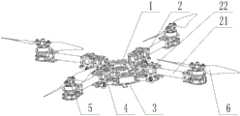
图2示出根据本发明一种优选实施方式的箭载旋翼无人机投射方法中旋翼无人机整体结构示意图;2 shows a schematic diagram of the overall structure of the rotor UAV in the projection method of the arrow-borne rotor UAV according to a preferred embodiment of the present invention;
图3示出根据本发明一种优选实施方式的箭载旋翼无人机投射方法中旋翼无人机禁锢在运载设备内时的结构示意图;3 shows a schematic structural diagram of the rotor UAV when the rotor UAV is imprisoned in the carrying device in the projection method of the arrow-borne rotor UAV according to a preferred embodiment of the present invention;
图4示出根据本发明一种优选实施方式的箭载旋翼无人机投射方法中运载设备上整流罩展开时的结构示意图;4 shows a schematic structural diagram of a fairing on a carrier device in a method for projecting an arrow-borne rotor UAV according to a preferred embodiment of the present invention when the fairing is unfolded;
图5示出根据本发明一种优选实施方式的箭载旋翼无人机投射方法中承托座截面图。FIG. 5 shows a cross-sectional view of a support seat in a method for projecting an arrow-borne rotor UAV according to a preferred embodiment of the present invention.
附图标号说明:Description of reference numbers:
1-机架1 - Rack
2-旋臂2 - Swivel arm
21-光杆段21 - polished rod segment
22-环形套筒22-Annular sleeve
3-连接盘3-connection plate
4-连杆4-Link
5-驱动电机5- Drive motor
6-螺旋桨6-Propeller
7-整流罩7- Fairing
71-弧形罩片71-Arc cover sheet
72-承托杆72-Support rod
8-承托座8-bearing seat
81-限位筒81-Limiting cylinder
82-承托板82-bearing plate
具体实施方式Detailed ways
下面通过附图和实施例对本发明进一步详细说明。通过这些说明,本发明的特点和优点将变得更为清楚明确。The present invention will be further described in detail below through the accompanying drawings and embodiments. The features and advantages of the present invention will become more apparent from these descriptions.
在这里专用的词“示例性”意为“用作例子、实施例或说明性”。这里作为“示例性”所说明的任何实施例不必解释为优于或好于其它实施例。尽管在附图中示出了实施例的各种方面,但是除非特别指出,不必按比例绘制附图。The word "exemplary" is used exclusively herein to mean "serving as an example, embodiment, or illustration." Any embodiment described herein as "exemplary" is not necessarily to be construed as preferred or advantageous over other embodiments. While various aspects of the embodiments are shown in the drawings, the drawings are not necessarily drawn to scale unless otherwise indicated.
本发明所述的运载设备包括火箭或火箭弹,所述火箭是靠火箭发动机喷射工质产生的反作用力向前推进的飞行器,所述火箭弹是由火箭筒或者火箭炮发射出的弹药,其中弹药的战斗部替换为本发明中的旋翼无人机。The carrying device of the present invention includes a rocket or a rocket, the rocket is an aircraft that is propelled forward by the reaction force generated by the ejection of a working medium by a rocket engine, and the rocket is an ammunition fired by a rocket launcher or a rocket launcher, wherein the ammunition is The warhead is replaced by the rotary-wing UAV in the present invention.
本发明所述的旋翼无人机是指四旋翼无人机、六旋翼无人机或者八旋翼无人机;The rotary-wing unmanned aerial vehicle described in the present invention refers to a quad-rotor unmanned aerial vehicle, a six-rotor unmanned aerial vehicle or an eight-rotor unmanned aerial vehicle;
本发明所述的铰接是指具有足够强度,不易断开的连接关系,这种连接允许彼此连接的两者之间做相对转动;本发明中一般通过转轴或者合页实现所述铰接。The hinge in the present invention refers to a connection relationship with sufficient strength that is not easy to be disconnected, and this connection allows relative rotation between the two connected to each other; in the present invention, the hinge is generally realized by a rotating shaft or a hinge.
根据本发明提供的箭载旋翼无人机机投射方法,所述箭载旋翼无人机包括运载设备和禁锢在所述运载设备内部的旋翼无人机;该方法中,将旋翼无人机禁锢在运载设备内,到达预定空域后,将旋翼无人机从所述运载设备内部放出;具体来说,如图1中所示,该方法包括如下步骤:According to the method for projecting an arrow-borne rotary-wing UAV provided by the present invention, the arrow-borne rotary-wing UAV includes a carrying device and a rotary-wing UAV imprisoned inside the carrying device; in this method, the rotor-wing UAV is imprisoned In the carrying equipment, after reaching the predetermined airspace, the rotor UAV is released from the carrying equipment; specifically, as shown in Figure 1, the method includes the following steps:
步骤1,将旋翼无人机禁锢在运载设备内,启动运载设备,使得运载设备飞向预定空域,最终到达预定空域;
步骤2,展开运载设备上的整流罩;
步骤3,弹出运载设备上禁锢的旋翼无人机;
步骤4,旋翼无人机悬臂回弹至水平位置,并启动工作。Step 4: The rotor drone cantilever bounces back to the horizontal position and starts work.
本发明中所述旋翼无人机在其旋臂2相对于机架1向下弯折时被禁锢在运载设备内,优选地,其弯折角度在90度左右时才能够使得无人机被禁锢在运载设备内;本发明中最优选的弯折角度是95度。In the present invention, the rotary-wing drone is imprisoned in the carrying device when its
当所述运载设备放开对所述无人机的禁锢时,所述无人机的旋臂2自动回弹至水平位置,并启动工作;具体来说,当所述旋臂2在弹力作用下自动回弹至水平位置,此时旋臂上的电机启动工作,带动螺旋桨旋转,使得无人机尽快在该空域悬停,与此同时,无人机上的其他相关设备也都启动工作,如导航系统、GPS定位系统等等,以使得无人机尽快确定所处方位,并移动至目标位置,开始执行预定的作业任务。When the carrying device releases the restraint on the drone, the
在一个优选的实施方式中,所述运载设备在到达预定空域时放开对所述无人机的禁锢,此时无人机距离预定的工作区域的距离较小,能够快速抵达;从而使得从接收到任务指令和相关目标信息到无人机就位并开始工作这段准备及航行时间大幅缩短,实现旋翼无人机的快速反应、快速机动,能够用于处置突发的紧急任务。In a preferred embodiment, the carrying device releases the restraint on the UAV when it reaches the predetermined airspace. At this time, the UAV is at a small distance from the predetermined working area and can reach quickly; The preparation and sailing time is greatly shortened from receiving the mission instruction and relevant target information to the time when the drone is in place and starts to work. It realizes the rapid response and rapid maneuvering of the rotary-wing drone, and can be used to deal with sudden emergency tasks.
本发明中所述放开对无人机的禁锢包括两个步骤,其一是整流罩展开,其二是通过承托板82将无人机从运载设备/承托座8中弹出。In the present invention, releasing the restraint of the UAV includes two steps, one is to unfold the fairing, and the other is to eject the UAV from the carrying device/support base 8 through the
在一个优选的实施方式中,如图2和图3中所示,该旋翼无人机还包括设置在机架1正下方的连接盘3,In a preferred embodiment, as shown in FIG. 2 and FIG. 3 , the rotary-wing UAV further comprises a connecting
通过所述连接盘3在竖直方向上的往复移动来控制旋臂2向下弯折或者回弹至水平位置。当连接盘3向下移动时,带动旋臂2向下弯折,当连接盘3向上移动时,带动旋臂2回弹至水平位置;同样地,当旋臂2向下弯折时也可以带动连接盘3向下移动,当旋臂2回弹至水平位置时也可以带动连接盘3向上移动。Through the reciprocating movement of the connecting
具体来说,优选地,在所述连接盘3上设置有连杆4,Specifically, preferably, a connecting
所述连杆4一端与连接盘3铰接,One end of the connecting
所述连杆4的另一端与旋臂2铰接。连杆4的数量与旋臂2的数量一致,彼此一一对应。The other end of the connecting
进一步优选地,所述旋臂2包括光杆段21,Further preferably, the
在所述光杆段21上套设有环形套筒22,所述环形套筒22可以沿着光杆段21往复滑动,或者所述环形套筒22固定在所述光杆段21上;An
所述连杆4与所述环形22铰接,即所述连杆4通过环形套筒22与旋臂2连铰。The connecting
优选地,在所述连接盘3和机架1上都设置有限位机构,使得旋臂只能在水平方向和向下弯折95度之间往复摆动。Preferably, a limiting mechanism is provided on both the connecting
优选地,在所述连接盘3和机架1之间设置有拉伸机构,Preferably, a stretching mechanism is provided between the connecting
所述拉伸机构用于拉动连接盘3向上靠近机架1,进而带动旋臂2回弹至水平位置。所述拉伸机构包括竖直设置的弹簧,该弹簧一直处于拉伸状态;当旋臂2向下弯折时,该拉伸机构中存储有较大的弹性势能,使得旋臂2上具有回复至水平位置的趋势,当限制、禁锢旋臂2的外力消失时,在该拉伸机构的作用下所述旋臂2可以较大的加速度从静止开始加速旋转,从向下弯折状态回弹至水平位置。The stretching mechanism is used to pull the connecting
进一步优选地,在连杆4一端与连接盘3铰接和连杆4与所述环形套筒22铰接的两个铰接位置设置扭转弹簧,该扭转弹簧也是所述拉伸机构的一部分,通过所述扭转弹簧增加旋臂2从水平位置到弯折状态所需要克服的弹力,进而增加在旋臂22向下弯折时,该拉伸机构中存储的弹性势能;该扭转弹簧还能够使得连杆4及旋臂2上的受到多个方向的作用力,确保连杆4及旋臂2按照设定轨迹移动,进而增强该系统的可靠性,在预定空域中,放开对无人机的禁锢时,无人机的旋臂一定能够回弹至水平位置。Further preferably, a torsion spring is provided at the two hinge positions where one end of the connecting
在一个优选的实施方式中,如图2、图3中所示,在所述旋臂2的端部设置有驱动电机5和螺旋桨6,驱动电机5用于控制螺旋桨6旋转,当所述无人机被禁锢到运载设备中时,所述电机5的控制电路处于待机状态;在旋臂与机架连接处设置有感应开关,当旋臂回复至水平位置时触发所述感应开关,当所述感应开关被触发后所述电机5的控制电路接通,电机5启动工作。该感应开关可以是电磁感应开关,也可以是机械触点开关,可以任意设置,只要能够实现上述功能即可。In a preferred embodiment, as shown in FIG. 2 and FIG. 3 , a drive motor 5 and a
其中,旋臂2与螺旋桨6之间留有预定空隙,所述电机5有一部分埋置在旋臂2中,另一部分裸露在外,在所述裸露在外部分的端部安装螺旋桨6。Wherein, a predetermined gap is left between the
优选地,所述旋臂2设置有多个,优选为4-8个,Preferably, there are multiple, preferably 4-8, said
当所述无人机被禁锢在运载设备内时,所述旋臂2对应的多个所述预定空隙呈圆形排布;运载设备通过该空隙禁锢所述无人机,即在该空隙内嵌入阻碍旋臂2回弹至水平位置的挡板,在旋臂上弹力的作用下,无人机整体即被固定、禁锢在运载设备中。所述挡板即为本发明中所述的限位筒。When the UAV is imprisoned in the carrying device, the plurality of predetermined gaps corresponding to the
在一个优选的实施方式中,如图2、图3和图4中所示,所述运载设备包括包覆在无人机外部的整流罩7和位于整流罩7内部下方的承托座8。In a preferred embodiment, as shown in FIG. 2 , FIG. 3 and FIG. 4 , the carrying device includes a fairing 7 covering the outside of the drone and a support base 8 located below the inside of the fairing 7 .
优选地,所述整流罩7用于保护其内部的无人机,并在到达预定空域时展开,以便于裸露出其内部的无人机;Preferably, the fairing 7 is used to protect the UAV inside, and is unfolded when reaching a predetermined airspace, so as to expose the UAV inside;
所述承托座8用于通过与所述预定空隙配合来禁锢无人机,并在到达预定空域时将无人机从承托座8中弹出。The support seat 8 is used to restrain the drone by cooperating with the predetermined gap, and to eject the drone from the support seat 8 when it reaches a predetermined airspace.
具体来说,如图5中所示,所述承托座8包括限位筒81和位于限位筒81内侧的承托板82,Specifically, as shown in FIG. 5 , the support base 8 includes a
所述呈限位筒81尺寸与所述预定空隙围成的圆形尺寸基本一致,使得该限位筒81刚好能够嵌入到所述空隙围成的圆形空间内,进而使得旋臂2的端部抵接在限位筒81的内圈壁面上,限位筒81能够阻碍旋臂2旋转,进而阻碍旋臂2回弹至水平位置,从而实现对无人机的禁锢;所述限位筒81的高度值为30-50mm,即限位筒的最高处与承托板82之间的距离为30-50mm,由于所述承托板82可以在竖直方向上移动,在计算该高度/距离时,所述承托板82处于可能的最低点。The size of the limiting
当所述运载设备禁锢无人机时,所述承托板82位于旋臂2的下方,承托板82与旋臂之间的距离较小,一般小于10mm,且所述承托板82可以在竖直方向上移动,其移动行程至少为30-50mm,即随着承托板82的移动,承托板82能够将无人机的旋臂从承托座8中推出,由于承托板82的移动速度较高,无人机与承托座8脱离时,无人机具有一定的初始速度,能够继续沿着该方向移动一定距离。When the carrier device imprisons the drone, the
所述承托板82可以通过电磁铁产生的斥力作为动力,也可以通过压缩弹簧作为动力,可以根据实际情况自行选择,能够实现上述往复移动并推动无人机的功能即可。The supporting
在一个优选的实施方式中,如图2、图3和图4中所示,所述整流罩7包括至少3个外形尺寸一致的弧形罩片71,各个弧形罩片71都与运载设备外壳铰接,且在彼此紧密贴合能够形成密闭壳体结构;In a preferred embodiment, as shown in FIG. 2 , FIG. 3 and FIG. 4 , the fairing 7 includes at least three arc-shaped
优选地,本发明中运载设备的外部包括有运载设备外壳和整流罩,其中整流罩位于前端/顶部并且与运载设备外壳相连;Preferably, the exterior of the carrier device in the present invention includes a carrier device housing and a fairing, wherein the fairing is located at the front/top and is connected to the carrier device housing;
在所述整流罩7上设置有锁扣机构,当所述各个弧形罩片71彼此紧密贴合时,该锁扣机构锁死各个弧形罩片71,使之彼此不能分离,且该锁扣机构是能够自动放开的,当其收到展开指令时,自动放开对弧形罩片71的锁定,使得多个弧形罩片71可以彼此分离,并旋转,从而裸露出整流罩内部的无人机;所述锁扣机构可以为电磁锁也可以是机械锁,可以设置成任意形式,只需能够满足上述要求即可。A locking mechanism is provided on the fairing 7. When the arc-shaped
优选地,所述运载设备中还设置有控制模块,该控制模块用于向所述锁扣机构发送展开指令;Preferably, a control module is further provided in the carrying device, and the control module is used to send a deployment instruction to the locking mechanism;
优选地,在执行步骤1启动运载设备前,向运载设备中灌装控制模块的设定参数;所述控制模块用于生成并发出控制所述整流罩展开的展开指令。Preferably, before performing
该控制模块可以基于时间信息生成并发出展开指令,也可以基于探测到的状态信息生成并发出展开指令,还可以基于地面指令生成并发出展开指令;The control module can generate and issue deployment instructions based on time information, can also generate and issue deployment instructions based on detected state information, and can also generate and issue deployment instructions based on ground instructions;
其中,所述时间信息是指预装的在预定时间后生成并发出展开指令,一般在运载设备启动前,灌装该预定时间,如40s后生成并发出展开指令;Wherein, the time information refers to a pre-installed command that is generated and issued after a predetermined time. Generally, before the launch of the carrier equipment, the predetermined time is filled, for example, a deployment command is generated and issued after 40s;
所述探测到的状态信息是指运载设备探测到的其自身的位置信息和速度信息,主要通过GPS接收模块、北斗接收模块等卫星定位模块探测、获知运载设备自身的位置信息和速度信息等相关信息,当探测到的状态信信息满足预设条件时生成并发出展开指令,如到达800m高度时生成并发出展开指令,或者到达东经116.3度,北纬39.95度附近时生成并发出展开指令,或者竖直方向速度值为0时生成并发出展开指令等;The detected status information refers to its own position information and speed information detected by the carrier equipment, mainly through the GPS receiver module, Beidou receiver module and other satellite positioning modules to detect and learn the carrier equipment's own position information and speed information and other related information. When the detected status information meets the preset conditions, a deployment command is generated and issued, such as when reaching a height of 800m, a deployment command is generated and issued, or when it reaches 116.3 degrees east longitude and 39.95 degrees north latitude, an deployment command is generated and issued, or a vertical When the speed value in the vertical direction is 0, an expansion command is generated and issued;
所述地面指令是指运载设备实时接收的由地面控制站发出的控制指令,通过该控制指令可以对运载设备做全方位的控制,包括校准、更改运载设备的飞行目标、飞行速度等,也包括立即展开指令,所述立即展开指令是指命令控制模块立即控制整流罩展开的指令。本发明中所述的地面站优选为运载设备的发射基地,装载有无线传输系统,能够保持与运载设备之间的无线电连接。The ground command refers to the control command issued by the ground control station received by the carrier equipment in real time. Through the control command, the carrier equipment can be controlled in all directions, including calibration, changing the flight target and flight speed of the carrier equipment, etc. The immediate deployment instruction refers to an instruction to command the control module to immediately control the deployment of the fairing. The ground station described in the present invention is preferably a transmitting base of the carrying equipment, loaded with a wireless transmission system, and capable of maintaining a radio connection with the carrying equipment.
所述控制模块在运载设备满足预设条件中的一种或多种时生成并发出展开指令;具体需要满足哪几种预设条件,也可以在启动前灌装在运载设备中;The control module generates and issues a deployment instruction when the carrying device satisfies one or more of the preset conditions; the specific preset conditions that need to be met can also be filled in the carrying device before starting;
所述预设条件包括:The preset conditions include:
所述运载设备的启动飞行时间达到设定参数中的时间值,The start-up flight time of the carrying device reaches the time value in the set parameter,
所述运载设备飞行至设定参数中的经纬度坐标位置及其容许误差,所述容许误差是指距离该经纬度坐标位置200~300米的圆形区域;通过设置该容许误差使得旋翼无人机在投掷过程中,即使火箭未能精确到达指定的经纬度的地点,也可以进入到该地点的容许误差范围内,所以能够确保整流罩顺利展开;另外,本发明中所述的预定空域包括该经纬度坐标位置及其容许误差,也包括该容许误差限定的区域以外的临近区域。The carrier device flies to the latitude and longitude coordinate position and its allowable error in the set parameters, and the allowable error refers to a circular area 200 to 300 meters away from the latitude and longitude coordinate position; During the throwing process, even if the rocket fails to accurately reach the specified latitude and longitude, it can still enter the allowable error range of the location, so the fairing can be ensured to unfold smoothly; in addition, the predetermined airspace described in the present invention includes the coordinates of the latitude and longitude. The position and its tolerance, including the adjacent area outside the area defined by the tolerance.
所述运载设备的飞行高度达到设定参数中的高度值,The flying height of the carrying equipment reaches the height value in the set parameter,
所述运载设备的飞行速度达到设定参数中的速度值;The flight speed of the carrying device reaches the speed value in the set parameter;
所述运载设备接收到由地面站发出的立即展开指令。The vehicle receives an immediate deployment command from the ground station.
即所述设定参数包括时间值、经纬度坐标位置、高度值和速度值等。优选地,通过设置所述设定参数,使得整流罩在运载设备达到预定空域时展开。That is, the setting parameters include time value, latitude and longitude coordinate position, altitude value, speed value, and the like. Preferably, by setting the setting parameters, the fairing is deployed when the carrying device reaches a predetermined airspace.
在一个优选的实施方式中,在各个弧形罩片71与运载设备铰接连接处设置有第二类感应开关,所述第二类感应开关与所述承托板82相连,用于控制承托板82启动工作;In a preferred embodiment, a second type of inductive switch is provided at the hinged connection between each arc-shaped
其中,当弧形罩片71旋转预定角度后能够触发与其对应的第二类感应开关,优选地,该预定角度值在90度以上;Wherein, when the arc-shaped
所述第二类感应开关有多个,当所有的第二类感应开关都被触发后控制承托板82启动工作,将无人机从运载设备/承托座8中弹出。There are multiple second-type inductive switches, and when all the second-type inductive switches are triggered, the
在一个优选的实施方式中,如图3中所示,在所述整流罩7内部还设置有承托杆72,该承托杆72一端固接在弧形罩片71内壁上,另一端与被禁锢在运载设备中的无人机的光杆段21相接触,用以承托/限制无人机,防止无人机在运载设备中振动或者摆动,当所述锁扣机构放开对弧形罩片71的锁定时,所述承托杆72随着弧形罩片71的转动而与所述光杆段21脱离。In a preferred embodiment, as shown in FIG. 3 , a support rod 72 is also provided inside the fairing 7 , one end of the support rod 72 is fixed on the inner wall of the arc-shaped
以上结合了优选的实施方式对本发明进行了说明,不过这些实施方式仅是范例性的,仅起到说明性的作用。在此基础上,可以对本发明进行多种替换和改进,这些均落入本发明的保护范围内。The present invention has been described above with reference to the preferred embodiments, but these embodiments are merely exemplary and serve only for illustrative purposes. On this basis, various substitutions and improvements can be made to the present invention, which all fall within the protection scope of the present invention.
Claims (10)
Translated fromChinesePriority Applications (1)
| Application Number | Priority Date | Filing Date | Title |
|---|---|---|---|
| CN201810726164.0ACN110683072A (en) | 2018-07-04 | 2018-07-04 | Rocket-borne rotor unmanned aerial vehicle projection method |
Applications Claiming Priority (1)
| Application Number | Priority Date | Filing Date | Title |
|---|---|---|---|
| CN201810726164.0ACN110683072A (en) | 2018-07-04 | 2018-07-04 | Rocket-borne rotor unmanned aerial vehicle projection method |
Publications (1)
| Publication Number | Publication Date |
|---|---|
| CN110683072Atrue CN110683072A (en) | 2020-01-14 |
Family
ID=69106405
Family Applications (1)
| Application Number | Title | Priority Date | Filing Date |
|---|---|---|---|
| CN201810726164.0APendingCN110683072A (en) | 2018-07-04 | 2018-07-04 | Rocket-borne rotor unmanned aerial vehicle projection method |
Country Status (1)
| Country | Link |
|---|---|
| CN (1) | CN110683072A (en) |
Citations (5)
| Publication number | Priority date | Publication date | Assignee | Title |
|---|---|---|---|---|
| CN104691748A (en)* | 2013-12-04 | 2015-06-10 | 中国直升机设计研究所 | Gun-launched unmanned helicopter and expansion method thereof |
| US20160137312A1 (en)* | 2014-05-06 | 2016-05-19 | Osterhout Group, Inc. | Unmanned aerial vehicle launch system |
| CN106184704A (en)* | 2016-08-08 | 2016-12-07 | 北京航空航天大学 | One is applicable to rocket-propelled quadrotor |
| US20170057635A1 (en)* | 2015-09-02 | 2017-03-02 | The Boeing Company | Drone launch systems and methods |
| US9616997B2 (en)* | 2008-06-16 | 2017-04-11 | Aurora Flight Sciences Corporation | Combined submersible vessel and unmanned aerial vehicle |
- 2018
- 2018-07-04CNCN201810726164.0Apatent/CN110683072A/enactivePending
Patent Citations (5)
| Publication number | Priority date | Publication date | Assignee | Title |
|---|---|---|---|---|
| US9616997B2 (en)* | 2008-06-16 | 2017-04-11 | Aurora Flight Sciences Corporation | Combined submersible vessel and unmanned aerial vehicle |
| CN104691748A (en)* | 2013-12-04 | 2015-06-10 | 中国直升机设计研究所 | Gun-launched unmanned helicopter and expansion method thereof |
| US20160137312A1 (en)* | 2014-05-06 | 2016-05-19 | Osterhout Group, Inc. | Unmanned aerial vehicle launch system |
| US20170057635A1 (en)* | 2015-09-02 | 2017-03-02 | The Boeing Company | Drone launch systems and methods |
| CN106184704A (en)* | 2016-08-08 | 2016-12-07 | 北京航空航天大学 | One is applicable to rocket-propelled quadrotor |
Non-Patent Citations (1)
| Title |
|---|
| 航空知识: ""大学航模队都玩什么?"黑精灵"变体无人机"", 《中国航空新闻网》* |
Similar Documents
| Publication | Publication Date | Title |
|---|---|---|
| CN110709320B (en) | System and method for intercepting and countering Unmanned Aerial Vehicles (UAVs) | |
| JP6716487B2 (en) | Weight-moving coaxial rotor helicopter | |
| US11542002B1 (en) | Unmanned aerial vehicle and control systems and methods | |
| JP2023178936A (en) | Falling trajectory control system | |
| KR20170016296A (en) | Release and capture of a fixedwing aircraft | |
| EP3638585A1 (en) | Launched unmanned aerial vehicle | |
| CN113306738B (en) | Working method of catapult-assisted take-off coaxial folding paddle unmanned aerial vehicle | |
| GB2498185A (en) | Grenade launched aerial surveillance vehicle | |
| CN112046751B (en) | Test bullet drop platform based on many rotor unmanned aerial vehicle | |
| CN112977824A (en) | Unmanned aerial vehicle system and method with detection and striking functions and convenient to carry by individual soldier | |
| CN110857148A (en) | Rotor UAV catapult on delivery system | |
| JP7545361B2 (en) | Fire extinguishing method using flying objects | |
| CN110871904B (en) | Separated carrying system for carrying rotor unmanned aerial vehicle | |
| GB2588283A (en) | Decoy system | |
| CN108088313A (en) | A kind of unmanned plane intercepting system | |
| US9716862B1 (en) | System and methods for capturing situational awareness | |
| CN110857149A (en) | Retrievable delivery system for rotary-wing UAV | |
| KR101694636B1 (en) | Manless flight device includes launcher for agriculturing | |
| CN115465450A (en) | Gun-shot cluster type folding rotor micro unmanned aerial vehicle | |
| JP7166587B2 (en) | Monitoring system | |
| CN110683069A (en) | Carry on rotor unmanned aerial vehicle's arrow machine system | |
| CN211196629U (en) | Unmanned aerial vehicle and unmanned aerial vehicle system for putting tear shells | |
| WO2016079747A1 (en) | Delivery of intelligence gathering devices | |
| CN110683072A (en) | Rocket-borne rotor unmanned aerial vehicle projection method | |
| CN110683071A (en) | Carrying system carrying rotor unmanned aerial vehicle |
Legal Events
| Date | Code | Title | Description |
|---|---|---|---|
| PB01 | Publication | ||
| PB01 | Publication | ||
| SE01 | Entry into force of request for substantive examination | ||
| SE01 | Entry into force of request for substantive examination | ||
| RJ01 | Rejection of invention patent application after publication | ||
| RJ01 | Rejection of invention patent application after publication | Application publication date:20200114 |