CN110680486A - A combination pressure locking screw and matching screwdriver - Google Patents
A combination pressure locking screw and matching screwdriverDownload PDFInfo
- Publication number
- CN110680486A CN110680486ACN201910859165.7ACN201910859165ACN110680486ACN 110680486 ACN110680486 ACN 110680486ACN 201910859165 ACN201910859165 ACN 201910859165ACN 110680486 ACN110680486 ACN 110680486A
- Authority
- CN
- China
- Prior art keywords
- component
- screwdriver
- external thread
- thread
- hollow
- Prior art date
- Legal status (The legal status is an assumption and is not a legal conclusion. Google has not performed a legal analysis and makes no representation as to the accuracy of the status listed.)
- Pending
Links
Images


Classifications
- A—HUMAN NECESSITIES
- A61—MEDICAL OR VETERINARY SCIENCE; HYGIENE
- A61B—DIAGNOSIS; SURGERY; IDENTIFICATION
- A61B17/00—Surgical instruments, devices or methods
- A61B17/56—Surgical instruments or methods for treatment of bones or joints; Devices specially adapted therefor
- A61B17/58—Surgical instruments or methods for treatment of bones or joints; Devices specially adapted therefor for osteosynthesis, e.g. bone plates, screws or setting implements
- A61B17/68—Internal fixation devices, including fasteners and spinal fixators, even if a part thereof projects from the skin
- A61B17/683—Internal fixation devices, including fasteners and spinal fixators, even if a part thereof projects from the skin comprising bone transfixation elements, e.g. bolt with a distal cooperating element such as a nut
- A—HUMAN NECESSITIES
- A61—MEDICAL OR VETERINARY SCIENCE; HYGIENE
- A61B—DIAGNOSIS; SURGERY; IDENTIFICATION
- A61B17/00—Surgical instruments, devices or methods
- A61B17/56—Surgical instruments or methods for treatment of bones or joints; Devices specially adapted therefor
- A61B17/58—Surgical instruments or methods for treatment of bones or joints; Devices specially adapted therefor for osteosynthesis, e.g. bone plates, screws or setting implements
- A61B17/68—Internal fixation devices, including fasteners and spinal fixators, even if a part thereof projects from the skin
- A61B17/84—Fasteners therefor or fasteners being internal fixation devices
- A61B17/86—Pins or screws or threaded wires; nuts therefor
- A61B17/8605—Heads, i.e. proximal ends projecting from bone
- A61B17/861—Heads, i.e. proximal ends projecting from bone specially shaped for gripping driver
- A61B17/8615—Heads, i.e. proximal ends projecting from bone specially shaped for gripping driver at the central region of the screw head
- A—HUMAN NECESSITIES
- A61—MEDICAL OR VETERINARY SCIENCE; HYGIENE
- A61B—DIAGNOSIS; SURGERY; IDENTIFICATION
- A61B17/00—Surgical instruments, devices or methods
- A61B17/56—Surgical instruments or methods for treatment of bones or joints; Devices specially adapted therefor
- A61B17/58—Surgical instruments or methods for treatment of bones or joints; Devices specially adapted therefor for osteosynthesis, e.g. bone plates, screws or setting implements
- A61B17/68—Internal fixation devices, including fasteners and spinal fixators, even if a part thereof projects from the skin
- A61B17/84—Fasteners therefor or fasteners being internal fixation devices
- A61B17/86—Pins or screws or threaded wires; nuts therefor
- A61B17/8605—Heads, i.e. proximal ends projecting from bone
- A61B17/861—Heads, i.e. proximal ends projecting from bone specially shaped for gripping driver
- A61B17/862—Heads, i.e. proximal ends projecting from bone specially shaped for gripping driver at the periphery of the screw head
- A—HUMAN NECESSITIES
- A61—MEDICAL OR VETERINARY SCIENCE; HYGIENE
- A61B—DIAGNOSIS; SURGERY; IDENTIFICATION
- A61B17/00—Surgical instruments, devices or methods
- A61B17/56—Surgical instruments or methods for treatment of bones or joints; Devices specially adapted therefor
- A61B17/58—Surgical instruments or methods for treatment of bones or joints; Devices specially adapted therefor for osteosynthesis, e.g. bone plates, screws or setting implements
- A61B17/68—Internal fixation devices, including fasteners and spinal fixators, even if a part thereof projects from the skin
- A61B17/84—Fasteners therefor or fasteners being internal fixation devices
- A61B17/86—Pins or screws or threaded wires; nuts therefor
- A61B17/8625—Shanks, i.e. parts contacting bone tissue
- A—HUMAN NECESSITIES
- A61—MEDICAL OR VETERINARY SCIENCE; HYGIENE
- A61B—DIAGNOSIS; SURGERY; IDENTIFICATION
- A61B17/00—Surgical instruments, devices or methods
- A61B17/56—Surgical instruments or methods for treatment of bones or joints; Devices specially adapted therefor
- A61B17/58—Surgical instruments or methods for treatment of bones or joints; Devices specially adapted therefor for osteosynthesis, e.g. bone plates, screws or setting implements
- A61B17/68—Internal fixation devices, including fasteners and spinal fixators, even if a part thereof projects from the skin
- A61B17/84—Fasteners therefor or fasteners being internal fixation devices
- A61B17/86—Pins or screws or threaded wires; nuts therefor
- A61B17/8685—Pins or screws or threaded wires; nuts therefor comprising multiple separate parts
- A—HUMAN NECESSITIES
- A61—MEDICAL OR VETERINARY SCIENCE; HYGIENE
- A61B—DIAGNOSIS; SURGERY; IDENTIFICATION
- A61B17/00—Surgical instruments, devices or methods
- A61B17/56—Surgical instruments or methods for treatment of bones or joints; Devices specially adapted therefor
- A61B17/58—Surgical instruments or methods for treatment of bones or joints; Devices specially adapted therefor for osteosynthesis, e.g. bone plates, screws or setting implements
- A61B17/88—Osteosynthesis instruments; Methods or means for implanting or extracting internal or external fixation devices
- A61B17/92—Impactors or extractors, e.g. for removing intramedullary devices
- A—HUMAN NECESSITIES
- A61—MEDICAL OR VETERINARY SCIENCE; HYGIENE
- A61B—DIAGNOSIS; SURGERY; IDENTIFICATION
- A61B90/00—Instruments, implements or accessories specially adapted for surgery or diagnosis and not covered by any of the groups A61B1/00 - A61B50/00, e.g. for luxation treatment or for protecting wound edges
- A61B90/06—Measuring instruments not otherwise provided for
- A—HUMAN NECESSITIES
- A61—MEDICAL OR VETERINARY SCIENCE; HYGIENE
- A61B—DIAGNOSIS; SURGERY; IDENTIFICATION
- A61B17/00—Surgical instruments, devices or methods
- A61B17/56—Surgical instruments or methods for treatment of bones or joints; Devices specially adapted therefor
- A61B17/58—Surgical instruments or methods for treatment of bones or joints; Devices specially adapted therefor for osteosynthesis, e.g. bone plates, screws or setting implements
- A61B17/68—Internal fixation devices, including fasteners and spinal fixators, even if a part thereof projects from the skin
- A61B2017/681—Alignment, compression, or distraction mechanisms
- A—HUMAN NECESSITIES
- A61—MEDICAL OR VETERINARY SCIENCE; HYGIENE
- A61B—DIAGNOSIS; SURGERY; IDENTIFICATION
- A61B17/00—Surgical instruments, devices or methods
- A61B17/56—Surgical instruments or methods for treatment of bones or joints; Devices specially adapted therefor
- A61B17/58—Surgical instruments or methods for treatment of bones or joints; Devices specially adapted therefor for osteosynthesis, e.g. bone plates, screws or setting implements
- A61B17/88—Osteosynthesis instruments; Methods or means for implanting or extracting internal or external fixation devices
- A61B17/92—Impactors or extractors, e.g. for removing intramedullary devices
- A61B2017/922—Devices for impaction, impact element
- A—HUMAN NECESSITIES
- A61—MEDICAL OR VETERINARY SCIENCE; HYGIENE
- A61B—DIAGNOSIS; SURGERY; IDENTIFICATION
- A61B90/00—Instruments, implements or accessories specially adapted for surgery or diagnosis and not covered by any of the groups A61B1/00 - A61B50/00, e.g. for luxation treatment or for protecting wound edges
- A61B90/06—Measuring instruments not otherwise provided for
- A61B2090/062—Measuring instruments not otherwise provided for penetration depth
Landscapes
- Health & Medical Sciences (AREA)
- Orthopedic Medicine & Surgery (AREA)
- Surgery (AREA)
- Life Sciences & Earth Sciences (AREA)
- Heart & Thoracic Surgery (AREA)
- Veterinary Medicine (AREA)
- Engineering & Computer Science (AREA)
- Biomedical Technology (AREA)
- Nuclear Medicine, Radiotherapy & Molecular Imaging (AREA)
- Medical Informatics (AREA)
- Molecular Biology (AREA)
- Animal Behavior & Ethology (AREA)
- General Health & Medical Sciences (AREA)
- Public Health (AREA)
- Neurology (AREA)
- Oral & Maxillofacial Surgery (AREA)
- Pathology (AREA)
- Surgical Instruments (AREA)
Abstract
Translated fromChineseDescription
Translated fromChinese技术领域technical field
本发明涉及医疗用骨折固定装置,尤其涉及应用于骨折块之间加压固定的内固定系统。The invention relates to a medical fracture fixation device, in particular to an internal fixation system applied to compression and fixation between fracture fragments.
背景技术Background technique
拉力螺钉是治疗一些需要手术的骨折,如关节内骨折、齿状突骨折等,最简单有效的内植物;现有技术中涉及的组合加压螺钉是一种非锁定的两组件拉力螺钉,其工作原理如下:组合加压螺钉加压过程中,螺钉一个组件围绕另一个组件旋转,使得螺钉长度缩短,闭合骨折缝,并在骨折块间产生加压力,重建骨折部位的结构稳定性。但是,如果作用于骨折块的外力大于维持骨折部位稳定的摩擦力,使得骨折块间发生旋转,则可能会导致螺钉的两组件之间发生旋转,从而使得组合螺钉长度变长,使得螺钉的加压作用下降,导致内固定失效,骨折畸形延迟愈合,甚至发生骨不愈合。Lag screws are the simplest and most effective implants to treat some fractures that require surgery, such as intra-articular fractures, odontoid fractures, etc. The combined compression screw involved in the prior art is a non-locking two-component lag screw. The working principle is as follows: during the compression process of the combined compression screw, one component of the screw rotates around the other component, so that the length of the screw is shortened, the fracture seam is closed, and compression force is generated between the fracture fragments to rebuild the structural stability of the fracture site. However, if the external force acting on the fracture fragment is greater than the frictional force that maintains the stability of the fracture site, so that rotation occurs between the fracture fragments, it may cause rotation between the two components of the screw, so that the length of the combined screw becomes longer, which makes the screw increase Decreased pressure, resulting in failure of internal fixation, delayed fracture union, and even bone nonunion.
发明内容SUMMARY OF THE INVENTION
本发明目的是:克服现有技术存在的不足,解决现有技术中存在的问题,提供一种可以锁定的组合加压螺钉,从而降低内固定失效、骨折畸形延迟愈合及骨不连的发生率。The purpose of the present invention is to overcome the deficiencies in the prior art, solve the problems in the prior art, and provide a lockable combined compression screw, thereby reducing the incidence of internal fixation failure, delayed fracture union and nonunion .
为解决上述技术问题,实现其发明目的,本发明提供了如下技术方案:一种组合加压锁定螺钉,包括加压结构,组件A和组件B,还设置有锁定结构,组件C和组件D;In order to solve the above-mentioned technical problems and achieve the purpose of the invention, the present invention provides the following technical solutions: a combined pressurized locking screw, comprising a pressurized structure, a component A and a component B, and a locking structure, a component C and a component D;
所述组件A设置有第一外螺纹1与第二外螺纹2,所述组件A靠近所述第二外螺纹2的一端设置有第一卡接结构3;The component A is provided with a first
所述组件B为中空圆柱状结构,所述组件B中空结构内设置第一内螺纹4和第二内螺纹5,所述第一内螺纹4与所述组件A的第二外螺纹2相匹配,以实现组件A和组件B的连接;所述组件B靠近所述第二内螺纹5的端部设置有加压结构;The component B is a hollow cylindrical structure, and the hollow structure of the component B is provided with a first
所述组件C包括设置在一端部的第二卡接结构6和设置在另一端部的中空圆柱状结构,所述中空圆柱状结构内设置有第三内螺纹7,所述第二卡接结构6与所述组件A的第一卡接结构3相互匹配,以实现组件A和组件C的连接;The component C includes a
所述组件D包括第三外螺纹8和第四外螺纹9,所述第三外螺纹8与所述组件C的第三内螺纹7相互匹配,以实现组件C和组件D的连接,所述第四外螺纹9与所述组件B的第二内螺纹5相互匹配,以实现组件B和组件D的连接。The component D includes a third
作为组合加压锁定螺钉一种优选方案:组件D第三外螺纹8和第四外螺纹9的螺距和螺纹旋转方向相同。As a preferred solution for the combined compression locking screw: the pitch and thread rotation direction of the third
作为组合加压锁定螺钉一种优选方案;组件A第二外螺纹2和组件B第一内螺纹4为第一对螺纹,组件C第三内螺纹7和组件D第三外螺纹8为第二对螺纹,组件B第二内螺纹5和组件D第四外螺纹9为第三对螺纹;第一对螺纹和第二、三对螺纹的螺纹间螺距和/或螺纹旋转方向不同,第二对螺纹和第三对螺纹的螺纹间螺距和螺纹旋转方向相同。As a preferred solution for the combination pressure locking screw; the second external thread 2 of component A and the first
作为组合加压锁定螺钉一种优选方案:所述组件B加压结构为设置在组件B靠近第二内螺纹5端部的膨大半球形结构,所述组件B加压结构横截面积为组件B最大的部分,其表面设置有第五外螺纹10,所述第五外螺纹10能够旋入骨骼或配套的接骨板。As a preferred solution of the combined compression locking screw: the compression structure of the component B is an enlarged hemispherical structure arranged at the end of the component B near the second
作为组合加压锁定螺钉一种优选方案:所述组件A的第一卡接结构3为中空结构,所述第一卡接结构3为中空棱柱状结构、中空十字结构、中空一字结构或者中空多角星形结构;所述组件C的第二卡接结构6为与所述组件A的第一卡接结构3相匹配的棱柱状结构、十字结构、一字结构或者多角星形结构。As a preferred solution for the combined compression locking screw: the
作为组合加压锁定螺钉一种优选方案:所述组件A的第一外螺纹1和第二外螺纹2之间设置有第一刻度线11,所述第一刻度线11用于指示所述组件B装配在所述组件A上的深度,即在所述组件B第一内螺纹4与组件A的第二外螺纹2相互匹配时,所述组件B靠近所述组件A的末端与所述第一刻度线11齐平。As a preferred solution for the combined compression locking screw: a
作为组合加压锁定螺钉一种优选方案:所述组件B的外表面设置有第二刻度线12,所述第二刻度线12用于指示所述组件B植入骨骼内部的深度,即装配好的组件A和组件B植入骨骼内部时,所述组件B上的第二刻度线12与骨表面平齐。As a preferred solution of the combination compression locking screw: the outer surface of the component B is provided with a
作为组合加压锁定螺钉一种优选方案:所述组件B加压结构内设置有第一中空十字结构14,通过所述第一中空十字结构14,所述组件B配套的起子能够操控所述组件B。As a preferred solution for the combined compression locking screw: the compression structure of the component B is provided with a first
作为组合加压锁定螺钉一种优选方案:所述组件D靠近所述第四外螺纹9的一端设置有第一十字结构17,通过所述第一十字结构17,所述组件D配套的起子能够操控所述组件D。As a preferred solution for the combined compression locking screw: the component D is provided with a
作为组合加压锁定螺钉一种优选方案:所述组件A和/或组件B的表面形成有凹凸不平结构,所述凹凸不平结构能够填充有利于骨愈合的药物。As a preferred solution of the combined compression locking screw: the surface of the component A and/or the component B is formed with an uneven structure, and the uneven structure can be filled with a drug that is beneficial to bone healing.
作为组合加压锁定螺钉一种优选方案:所述组件A和/或组件B的表面经喷砂或者多孔及羟基磷灰石突出处理形成有微孔,所述组件A和/或组件B表面喷砂或微孔有利于骨长入,提高骨-内固定结构的稳定性。As a preferred solution of the combined compression locking screw: the surface of the component A and/or the component B is sandblasted or porous and hydroxyapatite protruding to form micropores, and the surface of the component A and/or the component B is sprayed Sand or micropores facilitate bone ingrowth and improve the stability of the bone-internal fixation structure.
作为组合加压锁定螺钉一种优选方案:组件A、组件C和组件D可以是中空的,中空部分可以插入导针,提高操作的精确性。As a preferred solution of the combined compression locking screw: the component A, the component C and the component D can be hollow, and the hollow part can be inserted into the guide needle to improve the accuracy of the operation.
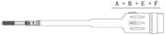
一种与组合加压锁定螺钉配套的起子,设置有起子E、起子F、起子G和起子H;A screwdriver matched with a combination pressure locking screw is provided with a screwdriver E, a screwdriver F, a screwdriver G and a screwdriver H;
所述起子E的一端包括有与所述组件A的第一卡接结构3相匹配的第三卡接结构13,所述第一卡接结构3和第三卡接结构13相匹配,从而所述起子E能够操控所述组件A;One end of the screwdriver E includes a
所述起子F的一端为第二中空十字结构15,所述组件B加压结构内设置有第一中空十字结构14,所述第二中空十字结构15与所述第一中空十字结构14相匹配,从而所述起子F能够操控所述组件;One end of the screwdriver F is a second
所述起子G的一端包括有与所述组件C的第三内螺纹7相匹配的第六外螺纹16,所述第三内螺纹7和所述第六外螺纹16相互匹配,从而所述起子G能够操控所述组件C;One end of the screwdriver G includes a sixth
所述起子H的一端为第二十字结构18,所述组件D靠近所述第四外螺纹9的一端设置有第一十字结构17,所述第二十字结构18与所述第一十字结构17相匹配,从而所述起子H能够操控所述组件D;One end of the screwdriver H is a
所述起子F为中空结构,在所述起子F通过第二中空十字结构15和第一中空十字结构14与所述组件B连接后,所述起子E、起子G和起子H能够分别穿过所述起子F实现对组件A、组件C和组件D的操控。The screwdriver F is a hollow structure. After the screwdriver F is connected to the component B through the second
作为所述起子一种优选方案:所述起子E和起子F分别设置有相互匹配的第一锁定结构19和第二锁定结构20,推动所述起子F上的第二锁定结构20,完成所述起子E和起子F之间的锁定;反向推动所述起子F上的第二锁定结构20,解除所述起子E和起子F之间的锁定。As a preferred solution of the screwdriver: the screwdriver E and the screwdriver F are respectively provided with a
本发明的有益技术效果至少包括如下:The beneficial technical effects of the present invention at least include the following:
1、本发明所述的组合加压锁定螺钉,螺钉加压和锁定的结构简单可靠,操作方便,学习曲线平缓,便于医生积累经验和提升手术的准确度:组件A第二外螺纹2和组件B第一内螺纹4为第一对螺纹,通过组件B以组件A为轴旋转,缩短螺钉长度,闭合骨折缝,提拉组件A第一螺纹1,并压缩第一螺纹1周围松质骨,结合组件B加压结构作用于骨骼/垫片/接骨板,产生加压力,加压固定骨折;组件C和组件D构成锁定组件A和组件B的结构,首先组件C第二卡接结构6和组件A第一卡接结构3相互匹配,实现了组件C对组件A的控制;组件D第三外螺纹8与组件C第三内螺纹7为第二对螺纹,实现组件D和组件C的连接,组件D第四外螺纹9与组件B第二内螺纹5为第三对螺纹,实现组件D和组件C的连接,第二对螺纹和第三对螺纹的螺距和螺纹旋转方向相同,使得组件D与组件B和组件C相互连接的过程顺滑地同步进行;拧紧组件D,实现组件D与组件B及组件C的锁定;组件A和组件B发生相对旋转的必要条件是第一对螺纹和第二、三对螺纹同步旋转,本专利创新性的设置使得上述这三对螺纹无法实现同步同速度旋转,即第一对螺纹和第二、三对螺纹的螺纹间螺距和/或螺纹旋转方向不同,组件A和组件B发生相对旋转的必要条件不存在,组件C和组件D和组件A和组件B连接后,组件A和组件B处于锁定状态。1. The combination compression locking screw of the present invention has a simple and reliable structure for screw compression and locking, easy operation, and a gentle learning curve, which is convenient for doctors to accumulate experience and improve the accuracy of surgery: component A second external thread 2 and component The first
存在一种基于本发明的实施方案,即:第一对螺纹与第二、三对螺纹的螺距和螺纹旋转方向相同,此时组件间的锁定依赖于拧紧第二、三对螺纹来实现,这种实施方式的锁定效果不如螺距和/或螺纹旋转方向不同的锁定效果好。There is an embodiment based on the present invention, that is: the pitch and thread rotation direction of the first pair of threads and the second and third pairs of threads are the same, and the locking between components at this time is achieved by tightening the second and third pairs of threads, which is The locking effect of this embodiment is not as good as the locking effect of different thread pitches and/or thread rotation directions.
2、本发明所述的组合加压锁定螺钉植入体内后,螺钉各组件间处于锁定状态,能够提高组合加压锁定螺钉本身结构稳定性,当外力作用于其中一个骨折块,使其要相对另外一个骨折块发生旋转时,处于锁定状态的组合加压螺钉控制另外一个骨折块与外力作用的骨折块同步旋转,从而降低骨折内固定失效、骨折畸形延迟愈合及骨不连的发生率。2. After the combined compression locking screw of the present invention is implanted into the body, the components of the screw are in a locked state, which can improve the structural stability of the combined compression locking screw itself. When an external force acts on one of the fracture fragments, it will be relatively When the other fracture fragment rotates, the combined compression screw in the locked state controls the synchronous rotation of the other fracture fragment and the fracture fragment acted by external force, thereby reducing the incidence of internal fixation failure, delayed fracture union and nonunion.
3、本发明所述的组合加压锁定螺钉的组件A和/或组件B的表面形成有凹凸不平结构,所述凹凸不平结构能够填充有利于骨愈合的药物,从而进一步加速骨愈合的速度;所述组件A和/或组件B的表面经喷砂或者多孔及羟基磷灰石突出处理形成有微孔,有利于骨长入,提高骨-内固定结构的稳定性,降低内固定失效的发生率。3. The surface of the component A and/or the component B of the combination compression locking screw of the present invention is formed with an uneven structure, and the uneven structure can be filled with drugs that are conducive to bone healing, thereby further accelerating the speed of bone healing; The surface of the component A and/or the component B is sandblasted or porous and hydroxyapatite protruding to form micropores, which is conducive to bone ingrowth, improves the stability of the bone-internal fixation structure, and reduces the occurrence of internal fixation failure. Rate.
4、本发明所述的组合加压锁定螺钉的结构设计使得医生在操作时能够更加进行标准化的操作,有利于迅速积累经验,提升医生手术的准确度,优化医生的学习效率,更有利于年轻医生提升水平与经验。4. The structural design of the combined compression locking screw of the present invention enables doctors to perform more standardized operations during operation, which is conducive to rapidly accumulating experience, improving the accuracy of doctors' operations, optimizing doctors' learning efficiency, and more conducive to young people. Doctors improve level and experience.
附图说明Description of drawings
图1是本发明一种组合加压锁定螺钉的组件A的结构示意图;FIG. 1 is a schematic structural diagram of an assembly A of a combined compression locking screw of the present invention;
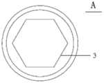
图2是组件A设置有第一卡接结构3的端部示意图;FIG. 2 is a schematic view of the end of the component A provided with the
图3是本发明一种组合加压锁定螺钉的组件B的结构示意图;FIG. 3 is a schematic structural diagram of a component B of a combined compression locking screw of the present invention;
图4是组件B设置有第一中空十字结构14的端部示意图;FIG. 4 is a schematic view of the end of the component B provided with the first
图5是组件A与组件B组合的结构示意图;5 is a schematic structural diagram of the combination of component A and component B;
图6是本发明一种组合加压锁定螺钉的组件C的结构示意图;FIG. 6 is a schematic structural diagram of an assembly C of a combined compression locking screw of the present invention;
图7是组件A与组件C组合的结构示意图;7 is a schematic structural diagram of the combination of component A and component C;
图8是本发明一种组合加压锁定螺钉的组件D的结构示意图;FIG. 8 is a schematic structural diagram of an assembly D of a combined compression locking screw of the present invention;
图9是组件D靠近第四外螺纹9一端的端部示意图;9 is a schematic view of the end of the component D close to one end of the fourth
图10是组件C和组件D组合的结构示意图;Figure 10 is a schematic structural diagram of the combination of component C and component D;
图11是组件B和组件D组合的结构示意图;11 is a schematic structural diagram of the combination of component B and component D;
图12是组件A、组件B、组件C和组件D组合的结构示意图;12 is a schematic structural diagram of the combination of component A, component B, component C and component D;
图13是本发明一种组合加压锁定螺钉配套起子E的结构示意图;FIG. 13 is a schematic structural diagram of a combined press-locking screw driver E according to the present invention;
图14是本发明一种组合加压锁定螺钉配套起子F的结构示意图;FIG. 14 is a schematic structural diagram of a combined press locking screw driver F according to the present invention;
图15是起子E和起子F组合的结构示意图;Fig. 15 is the structural representation of the combination of screwdriver E and screwdriver F;
图16是本发明的起子E和起子F组合后与组合A和组件B匹配的结构示意图;16 is a schematic structural diagram of the combination of the screwdriver E and the screwdriver F of the present invention and the combination of the combination A and the component B;
图17是本发明一种组合加压锁定螺钉配套的起子G的结构示意图;17 is a schematic structural diagram of a screwdriver G matched with a combination pressure locking screw according to the present invention;
图18是起子G和起子F组合的结构示意图;Fig. 18 is the structural representation of the combination of screwdriver G and screwdriver F;
图19是本发明的起子G和组件C连接的结构示意图Figure 19 is a schematic diagram of the structure of the connection between the screwdriver G and the component C of the present invention
图20是本发明一种组合加压锁定螺钉配套的起子H的结构示意图;FIG. 20 is a schematic structural diagram of a screwdriver H matched with a combination pressure locking screw according to the present invention;
图21是起子H和起子F组合的结构示意图;Fig. 21 is the structural representation of the combination of screwdriver H and screwdriver F;
图22是起子H与组件D连接的结构示意图;Fig. 22 is the structural representation that screwdriver H and component D are connected;
图23是本发明一种组合加压锁定螺钉的植入骨骼的结构示意图。FIG. 23 is a schematic structural diagram of a bone implantation combined with a compression locking screw according to the present invention.
具体实施方式Detailed ways
下面结合附图1-23及实施例对本发明技术方案进行详细说明,其中:1、第一外螺纹;2、第二外螺纹;3、第一卡接结构;4、第一内螺纹;5、第二内螺纹;6、第二卡接结构;7、第三内螺纹;8、第三外螺纹;9、第四外螺纹;10、第五外螺纹;11、第一刻度线;12、第二刻度线;13、第三卡接结构;14、第一中空十字结构;15、第二中空十字结构;16、第六外螺纹;17、第一十字结构;18、第二十字结构;19、第一锁定结构;20、第二锁定结构。The technical solution of the present invention will be described in detail below with reference to accompanying drawings 1-23 and the embodiments, wherein: 1. the first external thread; 2. the second external thread; 3. the first clamping structure; 4. the first internal thread; 5. , the second internal thread; 6, the second clamping structure; 7, the third internal thread; 8, the third external thread; 9, the fourth external thread; 10, the fifth external thread; 11, the first scale line; 12. The second scale line; 13. The third clamping structure; 14. The first hollow cross structure; 15. The second hollow cross structure; 16. The sixth external thread; 17. The first cross structure; structure; 19, the first locking structure; 20, the second locking structure.
如图1至图12所示,本发明公开了一种组合加压锁定螺钉,包括组件A、组件B、组件C和组件D。As shown in FIGS. 1 to 12 , the present invention discloses a combination compression locking screw, which includes component A, component B, component C and component D.
组件A请参考图1和图2,组件A为圆柱状结构,组件A表面设置有有第一外螺纹1与第二外螺纹2,组件A靠近第二外螺纹2一端设置有第一卡接结构3。Component A, please refer to FIG. 1 and FIG. 2. Component A is a cylindrical structure. The surface of component A is provided with a first
组件B请参考图3和图4,组件B为内设第一内螺纹4和第二内螺纹5的中空圆柱状结构;组件B靠近所述第二内螺纹5的端部设置有加压结构,所述组件B加压结构为膨大半球形结构,所述膨大半球形结构横截面积为组件B最大部分;所述组件B加压结构表面设置有能够旋入骨骼或配套接骨板的第五外螺纹10,当然,加压结构还可以是现有技术中的其它结构。Component B, please refer to FIG. 3 and FIG. 4. Component B is a hollow cylindrical structure with a first
一个实施例中,组件B的外表面设置有第二刻度线12(参见图3),所述第二刻度线12用于指导所述组件B植入骨骼内部的深度,即装配好的组件A和组件B植入骨骼内部时,所述组件B上的第二刻度线12与骨面平齐。此时也可以根据临床经验,记录组件B植入骨骼的最合适的深度In one embodiment, the outer surface of the component B is provided with a second scale line 12 (see FIG. 3 ), and the
图5为组件A和组件B组合的结构示意图,组件A的第二外螺纹2与组件B第一内螺纹4相互匹配,以实现组件A和组件B的连接。一个优选的实施例中,组件A的第一外螺纹1和第二外螺纹2之间设置有第一刻度线1(参见图1),所述第一刻度线1用于指导所述组件B装配在所述组件A上的深度,即在所述组件B通过第一内螺纹4旋转在所述组件A的第二外螺纹2上时,所述组件B靠近所述组件A的末端与所述第一刻度线11齐平。5 is a schematic structural diagram of the combination of component A and component B. The second external thread 2 of component A and the first
为了加速骨愈合的速度,在一个实施例中,将组建A和/或组件B的表面做成凹凸不平结构(此结构不影响组件A和组件B的功能),然后再凹凸不平结构上填充有利于骨愈合的药物。In order to accelerate the speed of bone healing, in one embodiment, the surface of component A and/or component B is made into an uneven structure (this structure does not affect the function of component A and component B), and then the uneven structure is filled with Medicines for bone healing.
为了降低螺钉在骨骼内松动的发生率,提高螺钉-骨结构的稳定性,在一个优选的实施例中,所述组件A和/或组件B的表面经喷砂或者多孔及羟基磷灰石突出处理形成有微孔,以利于骨长入。In order to reduce the incidence of screw loosening in the bone and improve the stability of the screw-bone structure, in a preferred embodiment, the surface of the component A and/or the component B is sandblasted or protruded with porous and hydroxyapatite The treatment is formed with micropores to facilitate bone ingrowth.
组件C请参考图6,组件C为圆柱状结构,包括设置在一端部的第二卡接结构6和设置在另一端部的中空结构,所述中空结构设置有第三内螺纹7;组件C的第二卡接结构6与组件A的第一卡接结构3相互匹配,相互咬合,以实现组件A和组件C的连接;需要说明的是,组件A的第一卡接结构3和组件C第二卡接结构6为一个具有凸起部、一个具有凹陷部,从而实现相互嵌接的卡接结构。Component C, please refer to FIG. 6, the component C is a cylindrical structure, including a
图7为组件C和组件A组合的一个实施例的结构示意图,所述组件A的第一卡接结构3具有凹陷部,即中空结构,具体的,第一卡接结构3可以是中空棱柱状结构(参考图2)、中空十字结构、中空一字结构或者中空多角星形结构等。相对应的,组件C的第二卡接结构6是与所述组件A的第一卡接结构3相匹配的凸起部,例如凸起的棱柱状结构、十字结构、一字结构或者多角星形结构等。7 is a schematic structural diagram of an embodiment of the combination of the component C and the component A. The
在另一个实施例中,组件A的第一卡接结构3具有凸起部,例如凸起的棱柱状结构、十字结构、一字结构或者多角星形结构等,所述组件C的第二卡接结构6具有与所述组件A的凸起部相匹配的凹陷部,即中空结构,例如中空棱柱状结构、中空十字结构、中空一字结构或者中空多角星形结构等。In another embodiment, the
当然,第一卡接结构3和第二卡接结构6还可以是其它的卡接结构,只要能实现将组件A和组件C连接固定的功能即可。Of course, the
组件D请参考图8和图9,其由两个直径不等的圆柱体连接而成,两柱体的轴线在一条直线上;直径小的圆柱体表面设置有第三外螺纹8,直径大的圆柱体表面设置有第四外螺纹9。所述第三外螺纹8与所述组件C的第三内螺纹7相匹配,以实现组件C和组件D的连接,连接后的结构示意图请参考图10。第四外螺纹9与所述组件B的第二内螺纹5相匹配,以实现组件B和组件D的连接,连接后的示意图请参考图11。Component D, please refer to Figure 8 and Figure 9, which is formed by connecting two cylinders with different diameters, and the axes of the two cylinders are on a straight line; the surface of the cylinder with a small diameter is provided with a third
图12为组件A、组件B、组件C和组件D组合的结构示意图,其组合过程可以是:在组件A和组件B通过第二外螺纹2与第一内螺纹4相连接,然后,组件C经组件B中空结构插入后第一卡接结构3与第二卡接结构6相匹配以实现组件A和组件C的连接,接下来,组件D插入组件B中空结构后旋转所述组件D,使其能够通过所述第三外螺纹8与第三内螺纹7与所述组件C相连,同时,组件D通过第四外螺纹9与第二内螺纹5与所述组件B相连。12 is a schematic structural diagram of the combination of component A, component B, component C and component D. The combination process can be as follows: component A and component B are connected with the first
如图13至图22所示,本发明还公开了一组上述组合加压锁定螺钉配套的起子,包括起子E、起子F、起子G和起子H。As shown in FIGS. 13 to 22 , the present invention also discloses a set of screwdrivers matching the above-mentioned combination compression locking screw, including screwdriver E, screwdriver F, screwdriver G and screwdriver H.
请参考图13,起子E为柱状结构,一端包括有与组件A的第一卡接结构3相匹配的第三卡接结构13,当第一卡接结构3和第三卡接结构13嵌接之后,所述起子E能够操控所述组件A。Please refer to FIG. 13 , the screwdriver E is a columnar structure, and one end includes a
请参考图14,起子F为中空柱状结构,一端的端面设置有第二中空十字结构15,组件B加压结构内设置有第一中空十字结构14,所述第二中空十字结构15与所述第一中空十字结构14嵌接,从而所述起子F能够操控所述组件B。Please refer to FIG. 14 , the screwdriver F is a hollow columnar structure, the end face of one end is provided with a second
请参考图17,起子G为柱状结构,一端包括有与所述组件C的第三内螺纹7相匹配的第六外螺纹16,起子G另一端设置有粗糙面,利于起子G操控;所述第三内螺纹7和第六外螺纹16匹配后,起子G能够操控所述组件C,如图19所示。Please refer to FIG. 17 , the screwdriver G is a columnar structure, one end includes a sixth
请参考图20,起子H柱状结构,一端为的第二十字结构18,组件D靠近所述第四外螺纹9的一端设置有第一十字结构17,凸起的第二十字结构18和第一十字结构17嵌接后,所述起子H能够操控所述组件D,如图22所示。Please refer to FIG. 20 , the screwdriver H has a columnar structure with a
请参考图15、图18和图21,所述起子E、起子G和起子H的柱状结构外直径小于或等于起子F中空结构的内直径,所述起子F通过第二中空十字结构15和第一中空十字结构14与所述组件B连接后,所述起子E、起子G和起子H能够分别穿过所述起子F实现对组件A、组件C和组件D的操控。Please refer to FIG. 15 , FIG. 18 and FIG. 21 , the outer diameter of the columnar structure of the screwdriver E, screwdriver G and screwdriver H is less than or equal to the inner diameter of the hollow structure of the screwdriver F, and the screwdriver F passes through the second
一个优选的实施例中,所述起子E和起子F分别设置有相互匹配的第一锁定结构19和第二锁定结构20,推动所述起子F上的第二锁定结构20,将第二锁定结构20和第一锁定结构19锁定,完成所述起子E和起子F之间的锁定;反向推动所述起子F上的第二锁定结构20,解除第二锁定结构20和第一锁定结构19之间的锁定状态,从而解除了所述起子E和起子F之间的锁定。In a preferred embodiment, the screwdriver E and the screwdriver F are respectively provided with a
在一个具体的实施例中,所述起子E和起子F的表面分别设置有刻度,用来记录起子F相对于起子E的旋转角度。In a specific embodiment, the surfaces of the screwdriver E and the screwdriver F are respectively provided with scales for recording the rotation angle of the screwdriver F relative to the screwdriver E.
请继续参考图23,其为所述组合加压锁定螺钉植入骨骼内的结构示意图,其组合过程可以是:首先,所述组合加压锁定螺钉组件A和组件B根据组件A第一刻度线11装配后植入骨骼内,当组件B第二刻度线12与骨表面平齐时螺钉停止植入;然后,起子E控制控制组件A不发生转动,起子F旋转组件B第一内螺纹4在组件A第二外螺纹2上旋转(第一对螺纹),使得螺钉总体长度缩短,闭合骨折缝,并提拉组件A第一外螺纹1,压缩第一外螺纹1,结合组件B加压结构作用于骨/垫片/接骨板表面,产生加压力,重建骨折部位的结构稳定性;接下来,起子G经起子F中空结构将组件C插入组件B中空结构内,使得组件C第二卡接结构6和组件A第一卡接结构3相互嵌接,实现组件C和组件A的连接;下一步,起子H经起子F中空结构将组件D插入组件B中空结构内,旋转组件D,实现组件D第三外螺纹8和组件C第三内螺纹7(第二对螺纹)及组件D第四外螺纹9和组件B第二内螺纹5(第三对螺纹)的同步匹配,本发明专利独特的设计,即:第二对螺纹和第三对螺纹螺距及螺纹旋转方向相同,使得组件D与组件B和组件C的连接平滑进行;最后,拧紧组件D,使得组件D与组件B和组件C锁定,此时,组件A和组件B发生旋转的先决条件是三对螺纹的螺距及螺纹旋转方向相同,但本发明专利独特的设计,即:第一对螺纹和第二、三对螺纹螺距和/或螺纹旋转方向不同,使得组件A和组件B发生旋转的先决条件不存在,组件A和组件B因此处于锁定状态;锁定状态的组件A和组件B具有独特的优势:当外力作用于其中一个骨折块,使其要相对另外一个骨折块发生旋转时,处于锁定状态的组合加压螺钉控制另外一个骨折块与外力作用的骨折块同步旋转,使得两个骨折块保持联动,从而降低骨折内固定失效、骨折畸形延迟愈合及骨不连的发生率。Please continue to refer to FIG. 23 , which is a schematic structural diagram of the combination compression locking screw implanted into the bone. The combination process can be as follows: First, the combination compression locking screw component A and component B are based on the first scale of component A. After the
需要说明的是,本发明专利涉及的所谓同侧关节内骨折块是指与组件B的加压结构相接触的一侧,所谓对侧关节内骨折块是指与同侧关节内骨折块相对应的骨折块。It should be noted that the so-called ipsilateral intra-articular fracture fragment involved in the patent of the present invention refers to the side that is in contact with the compression structure of component B, and the so-called contralateral intra-articular fracture fragment refers to the intra-articular fracture fragment corresponding to the ipsilateral side. of fracture fragments.
本发明所述的技术方案适用于多种骨折的治疗,尤其是对关节内骨折、股骨颈骨折、齿状突骨折等。下面具体结合胫骨平台骨折手术中有关本发明所述装置的使用过程,进行详细的说明:The technical solution of the present invention is suitable for the treatment of various fractures, especially for intra-articular fractures, femoral neck fractures, odontoid fractures and the like. The following is a detailed description of the use process of the device of the present invention in the tibial plateau fracture operation:
第一步:按标准手术流程,消毒铺单并按照标准手术入路暴露骨折,复位并利用克氏针或复位钳临时固定骨折,透视确认复位良好;用手术专用转头在同侧关节内骨折块合适的部位打孔至对侧关节内骨折块并测量钉孔深度。Step 1: According to the standard surgical procedure, sterilize and lay the sheet and expose the fracture according to the standard surgical approach, reduce and temporarily fix the fracture with Kirschner wire or reduction forceps, and confirm that the reduction is good by fluoroscopy; use a special rotary head for surgery to fix the fracture in the ipsilateral joint. The appropriate part of the block was drilled to the contralateral intra-articular fragment and the depth of the nail hole was measured.
第二步:根据测量钉孔的深度,选择合适长度的组件A和组件B并装配好,使得组件B的末端与组件A上第一刻度线11齐平。根据需要,在组件A和组件B表面凹槽结构填充促进骨愈合的物质,如骨形态发生蛋白等。Step 2: According to the depth of the measured nail hole, select the appropriate length of component A and component B and assemble them so that the end of component B is flush with the
第三步:将起子E和起子F组合好,使得起子E末端的第三卡接结构13与组件A尾部第一卡接结构3嵌接,起子F末端第二中空十字结构15与组件B第一中空十字结构14嵌接;接下来,推动外起子F上的第二锁定结构20,使之作用于内起子E上第一锁定结构19,完成起子E和起子F之间的锁定,这一状态下,组件A、组件B、起子E和起子F是一个整体,如图16所示。接下来,通过已锁定的起子E和起子F将装配好的组件A和组件B植入骨骼内,直至组件B上第二刻度线12与骨面平齐。然后反向推动外起子F上的第二锁定结构20,使得起子E和起子F之间解锁,起子E控制组件A不旋转,顺时针旋转起子F,使得组件B以组件A为轴旋转,缩短螺钉长度,闭合骨折缝,并提拉组件A第一外螺纹1,压缩第一外螺纹1,结合组件B加压结构作用于骨表面,产生加压力,重建骨折部位的结构稳定性。医生在这一过程中仔细体检加压力的变化,并根据起子E与起子F设置的刻度,确定合适拧紧螺钉时的旋转角度;记录角度,为下次操作积累临床经验;Step 3: Assemble the screwdriver E and the screwdriver F, so that the
第四步:螺钉锁定:(1)、根据选择的组件A和组件B,选择长度合适的组件C,将起子G的第六外螺纹16与组件C的第三内螺纹7相互匹配,实现起子G对组件C的操控;(2)、将起子E从起子F中取出,起子G经起子F中空结构将组件C插入组件B中空结构内,使得组件C第二卡接结构6和组件A第一卡接结构3相互嵌接,实现组件C和组件A的连接;(3)反向转动起子G,使得起子G和组件C分离,将起子G从起子F中取出;(4)、起子H的第二十字结构18和组件D第一十字结构17相互匹配,实现起子H对组件D的操控;(5)、起子H经起子F中空结构将组件D插入组件B中空结构内,起子F控制组件B不发生转动,旋转起子H,本发明专利独特的设计,即,组件D第三外螺纹8和组件C第三内螺纹7及组件D第四外螺纹9和组件B第二内螺纹5这两对螺纹螺距及螺纹方向相同,使得组件D与组件A和组件B同步匹配;(6)拧紧组件D,此时组件A和组件B处于锁定状态。Step 4: Screw locking: (1) According to the selected component A and component B, select component C with a suitable length, and match the sixth
第五步:根据需要,按照相同的流程植入多根组合加压锁定螺钉再次透视确认骨折复位及内固定位置良好,冲洗创面并确切止血后依次缝合至皮肤;Step 5: According to the needs, according to the same process, implant multiple combined compression locking screws to confirm the fracture reduction and internal fixation position by fluoroscopy again, rinse the wound surface and suture it to the skin in turn after exact hemostasis;
第六步:根据不同病情,操作中的相关尺寸可以不断调整;Step 6: According to different conditions, the relevant dimensions in the operation can be continuously adjusted;
以上仅为本发明的优选实施例,并非因此限制本发明的专利范围,凡是利用本发明说明书及附图内容所作的等效结构或等效流程变换,或直接或间接运用在其他相关的技术领域,均同理包括在本发明的专利保护范围内。The above are only preferred embodiments of the present invention, and are not intended to limit the scope of the present invention. Any equivalent structure or equivalent process transformation made by using the contents of the description and drawings of the present invention, or directly or indirectly applied in other related technical fields , are similarly included in the scope of patent protection of the present invention.
Claims (10)
Translated fromChinesePriority Applications (1)
| Application Number | Priority Date | Filing Date | Title |
|---|---|---|---|
| CN201910859165.7ACN110680486A (en) | 2019-09-11 | 2019-09-11 | A combination pressure locking screw and matching screwdriver |
Applications Claiming Priority (1)
| Application Number | Priority Date | Filing Date | Title |
|---|---|---|---|
| CN201910859165.7ACN110680486A (en) | 2019-09-11 | 2019-09-11 | A combination pressure locking screw and matching screwdriver |
Publications (1)
| Publication Number | Publication Date |
|---|---|
| CN110680486Atrue CN110680486A (en) | 2020-01-14 |
Family
ID=69109034
Family Applications (1)
| Application Number | Title | Priority Date | Filing Date |
|---|---|---|---|
| CN201910859165.7APendingCN110680486A (en) | 2019-09-11 | 2019-09-11 | A combination pressure locking screw and matching screwdriver |
Country Status (1)
| Country | Link |
|---|---|
| CN (1) | CN110680486A (en) |
Cited By (1)
| Publication number | Priority date | Publication date | Assignee | Title |
|---|---|---|---|---|
| CN113274111A (en)* | 2021-06-15 | 2021-08-20 | 苏州惠卫达医疗科技有限公司 | Mixed locking bone fracture plate system and matched screwdriver |
Citations (5)
| Publication number | Priority date | Publication date | Assignee | Title |
|---|---|---|---|---|
| CN102319103A (en)* | 2011-09-15 | 2012-01-18 | 徐达强 | Pressurized locking combined screw system and special composite screwdriver |
| US20130245626A1 (en)* | 2011-09-08 | 2013-09-19 | Abraham Lavi | Intramedullary Nail and Nail Combinations |
| CN105662570A (en)* | 2016-03-18 | 2016-06-15 | 徐达强 | Bone cement type combined lag screw, bone cement injection system and compound screwdriver |
| CN108119508A (en)* | 2016-11-29 | 2018-06-05 | 刘义稳 | The locking combination nut of prefastening |
| CN211658308U (en)* | 2019-09-11 | 2020-10-13 | 杨惠林 | Combined pressurizing locking screw and matched screwdriver |
- 2019
- 2019-09-11CNCN201910859165.7Apatent/CN110680486A/enactivePending
Patent Citations (5)
| Publication number | Priority date | Publication date | Assignee | Title |
|---|---|---|---|---|
| US20130245626A1 (en)* | 2011-09-08 | 2013-09-19 | Abraham Lavi | Intramedullary Nail and Nail Combinations |
| CN102319103A (en)* | 2011-09-15 | 2012-01-18 | 徐达强 | Pressurized locking combined screw system and special composite screwdriver |
| CN105662570A (en)* | 2016-03-18 | 2016-06-15 | 徐达强 | Bone cement type combined lag screw, bone cement injection system and compound screwdriver |
| CN108119508A (en)* | 2016-11-29 | 2018-06-05 | 刘义稳 | The locking combination nut of prefastening |
| CN211658308U (en)* | 2019-09-11 | 2020-10-13 | 杨惠林 | Combined pressurizing locking screw and matched screwdriver |
Cited By (1)
| Publication number | Priority date | Publication date | Assignee | Title |
|---|---|---|---|---|
| CN113274111A (en)* | 2021-06-15 | 2021-08-20 | 苏州惠卫达医疗科技有限公司 | Mixed locking bone fracture plate system and matched screwdriver |
Similar Documents
| Publication | Publication Date | Title |
|---|---|---|
| US7909858B2 (en) | Bone plate systems using provisional fixation | |
| JP4971195B2 (en) | Plates and screws for fracture treatment | |
| JP4468814B2 (en) | Fixation system consisting of nails and screws to improve the fixation of proximal fractures of the humerus | |
| KR102190533B1 (en) | Bone fixation system | |
| US20050209594A1 (en) | Orthopedic system having detachable bone anchors | |
| KR20130069578A (en) | Bone fixation system including k-wire compression | |
| CN111544104B (en) | A mortise and tenon structure splicing type fracture reduction and compression internal fixation device | |
| US12232788B2 (en) | Bone fixation system | |
| US7101376B2 (en) | Interlocking IM Nails with threaded guidewire | |
| CN211658308U (en) | Combined pressurizing locking screw and matched screwdriver | |
| CN110680486A (en) | A combination pressure locking screw and matching screwdriver | |
| WO2012167729A1 (en) | Torsion-measurable combination-type compression locking device for joint fracture | |
| WO2017166423A1 (en) | Locking and external-fixation device for treatment of tibial fracture | |
| CN102406516A (en) | Pressurized combination screw capable of quantizing torsion and composite screwdriver thereof | |
| CN215349369U (en) | Improved structure of composite bone lock | |
| CN112472265B (en) | Intramedullary implant system | |
| CN204219019U (en) | Become the locking bone screw of helicitic texture | |
| CN203291001U (en) | Thread type lag screw system and special composite screw driver thereof | |
| CN210727849U (en) | Mortise and tenon structure splicing type fracture reduction pressurization internal fixation device | |
| CN206044712U (en) | Universal lock fixed board on front side of near end of thighbone | |
| CN206044713U (en) | Straight type lockplate on front side of femur | |
| TW201711642A (en) | Bone plate set having screws with a plurality of threaded areas | |
| CN104352276A (en) | Locking bone joining screw of variable thread structure | |
| CN221635993U (en) | Femoral condyle fracture fixing device | |
| CN207286124U (en) | Universal lock fixed board outside near end of thighbone joint |
Legal Events
| Date | Code | Title | Description |
|---|---|---|---|
| PB01 | Publication | ||
| PB01 | Publication | ||
| SE01 | Entry into force of request for substantive examination | ||
| SE01 | Entry into force of request for substantive examination | ||
| AD01 | Patent right deemed abandoned | Effective date of abandoning:20250516 | |
| AD01 | Patent right deemed abandoned |