CN110678918B - Indicating device and battery pack - Google Patents
Indicating device and battery packDownload PDFInfo
- Publication number
- CN110678918B CN110678918BCN201880013243.5ACN201880013243ACN110678918BCN 110678918 BCN110678918 BCN 110678918BCN 201880013243 ACN201880013243 ACN 201880013243ACN 110678918 BCN110678918 BCN 110678918B
- Authority
- CN
- China
- Prior art keywords
- light
- light guide
- indicating device
- battery
- top surface
- Prior art date
- Legal status (The legal status is an assumption and is not a legal conclusion. Google has not performed a legal analysis and makes no representation as to the accuracy of the status listed.)
- Expired - Fee Related
Links
Images


Classifications
- H—ELECTRICITY
- H01—ELECTRIC ELEMENTS
- H01M—PROCESSES OR MEANS, e.g. BATTERIES, FOR THE DIRECT CONVERSION OF CHEMICAL ENERGY INTO ELECTRICAL ENERGY
- H01M10/00—Secondary cells; Manufacture thereof
- H01M10/42—Methods or arrangements for servicing or maintenance of secondary cells or secondary half-cells
- H01M10/48—Accumulators combined with arrangements for measuring, testing or indicating the condition of cells, e.g. the level or density of the electrolyte
- H01M10/488—Cells or batteries combined with indicating means for external visualization of the condition, e.g. by change of colour or of light density
- H—ELECTRICITY
- H01—ELECTRIC ELEMENTS
- H01M—PROCESSES OR MEANS, e.g. BATTERIES, FOR THE DIRECT CONVERSION OF CHEMICAL ENERGY INTO ELECTRICAL ENERGY
- H01M10/00—Secondary cells; Manufacture thereof
- H01M10/42—Methods or arrangements for servicing or maintenance of secondary cells or secondary half-cells
- H01M10/425—Structural combination with electronic components, e.g. electronic circuits integrated to the outside of the casing
- F—MECHANICAL ENGINEERING; LIGHTING; HEATING; WEAPONS; BLASTING
- F21—LIGHTING
- F21V—FUNCTIONAL FEATURES OR DETAILS OF LIGHTING DEVICES OR SYSTEMS THEREOF; STRUCTURAL COMBINATIONS OF LIGHTING DEVICES WITH OTHER ARTICLES, NOT OTHERWISE PROVIDED FOR
- F21V23/00—Arrangement of electric circuit elements in or on lighting devices
- F21V23/04—Arrangement of electric circuit elements in or on lighting devices the elements being switches
- G—PHYSICS
- G01—MEASURING; TESTING
- G01R—MEASURING ELECTRIC VARIABLES; MEASURING MAGNETIC VARIABLES
- G01R31/00—Arrangements for testing electric properties; Arrangements for locating electric faults; Arrangements for electrical testing characterised by what is being tested not provided for elsewhere
- G01R31/36—Arrangements for testing, measuring or monitoring the electrical condition of accumulators or electric batteries, e.g. capacity or state of charge [SoC]
- G—PHYSICS
- G02—OPTICS
- G02B—OPTICAL ELEMENTS, SYSTEMS OR APPARATUS
- G02B6/00—Light guides; Structural details of arrangements comprising light guides and other optical elements, e.g. couplings
- G—PHYSICS
- G02—OPTICS
- G02B—OPTICAL ELEMENTS, SYSTEMS OR APPARATUS
- G02B6/00—Light guides; Structural details of arrangements comprising light guides and other optical elements, e.g. couplings
- G02B6/0001—Light guides; Structural details of arrangements comprising light guides and other optical elements, e.g. couplings specially adapted for lighting devices or systems
- G02B6/0011—Light guides; Structural details of arrangements comprising light guides and other optical elements, e.g. couplings specially adapted for lighting devices or systems the light guides being planar or of plate-like form
- G02B6/0033—Means for improving the coupling-out of light from the light guide
- G02B6/0035—Means for improving the coupling-out of light from the light guide provided on the surface of the light guide or in the bulk of it
- G02B6/0045—Means for improving the coupling-out of light from the light guide provided on the surface of the light guide or in the bulk of it by shaping at least a portion of the light guide
- G—PHYSICS
- G02—OPTICS
- G02B—OPTICAL ELEMENTS, SYSTEMS OR APPARATUS
- G02B6/00—Light guides; Structural details of arrangements comprising light guides and other optical elements, e.g. couplings
- G02B6/0001—Light guides; Structural details of arrangements comprising light guides and other optical elements, e.g. couplings specially adapted for lighting devices or systems
- G02B6/0011—Light guides; Structural details of arrangements comprising light guides and other optical elements, e.g. couplings specially adapted for lighting devices or systems the light guides being planar or of plate-like form
- G02B6/0066—Light guides; Structural details of arrangements comprising light guides and other optical elements, e.g. couplings specially adapted for lighting devices or systems the light guides being planar or of plate-like form characterised by the light source being coupled to the light guide
- G02B6/0068—Arrangements of plural sources, e.g. multi-colour light sources
- G—PHYSICS
- G09—EDUCATION; CRYPTOGRAPHY; DISPLAY; ADVERTISING; SEALS
- G09F—DISPLAYING; ADVERTISING; SIGNS; LABELS OR NAME-PLATES; SEALS
- G09F13/00—Illuminated signs; Luminous advertising
- G09F13/20—Illuminated signs; Luminous advertising with luminescent surfaces or parts
- G09F13/22—Illuminated signs; Luminous advertising with luminescent surfaces or parts electroluminescent
- H—ELECTRICITY
- H01—ELECTRIC ELEMENTS
- H01M—PROCESSES OR MEANS, e.g. BATTERIES, FOR THE DIRECT CONVERSION OF CHEMICAL ENERGY INTO ELECTRICAL ENERGY
- H01M50/00—Constructional details or processes of manufacture of the non-active parts of electrochemical cells other than fuel cells, e.g. hybrid cells
- H01M50/20—Mountings; Secondary casings or frames; Racks, modules or packs; Suspension devices; Shock absorbers; Transport or carrying devices; Holders
- H01M50/204—Racks, modules or packs for multiple batteries or multiple cells
- H—ELECTRICITY
- H01—ELECTRIC ELEMENTS
- H01M—PROCESSES OR MEANS, e.g. BATTERIES, FOR THE DIRECT CONVERSION OF CHEMICAL ENERGY INTO ELECTRICAL ENERGY
- H01M50/00—Constructional details or processes of manufacture of the non-active parts of electrochemical cells other than fuel cells, e.g. hybrid cells
- H01M50/20—Mountings; Secondary casings or frames; Racks, modules or packs; Suspension devices; Shock absorbers; Transport or carrying devices; Holders
- H01M50/262—Mountings; Secondary casings or frames; Racks, modules or packs; Suspension devices; Shock absorbers; Transport or carrying devices; Holders with fastening means, e.g. locks
- H—ELECTRICITY
- H02—GENERATION; CONVERSION OR DISTRIBUTION OF ELECTRIC POWER
- H02J—CIRCUIT ARRANGEMENTS OR SYSTEMS FOR SUPPLYING OR DISTRIBUTING ELECTRIC POWER; SYSTEMS FOR STORING ELECTRIC ENERGY
- H02J7/00—Circuit arrangements for charging or depolarising batteries or for supplying loads from batteries
- F—MECHANICAL ENGINEERING; LIGHTING; HEATING; WEAPONS; BLASTING
- F21—LIGHTING
- F21W—INDEXING SCHEME ASSOCIATED WITH SUBCLASSES F21K, F21L, F21S and F21V, RELATING TO USES OR APPLICATIONS OF LIGHTING DEVICES OR SYSTEMS
- F21W2111/00—Use or application of lighting devices or systems for signalling, marking or indicating, not provided for in codes F21W2102/00 – F21W2107/00
- F—MECHANICAL ENGINEERING; LIGHTING; HEATING; WEAPONS; BLASTING
- F21—LIGHTING
- F21Y—INDEXING SCHEME ASSOCIATED WITH SUBCLASSES F21K, F21L, F21S and F21V, RELATING TO THE FORM OR THE KIND OF THE LIGHT SOURCES OR OF THE COLOUR OF THE LIGHT EMITTED
- F21Y2103/00—Elongate light sources, e.g. fluorescent tubes
- F21Y2103/30—Elongate light sources, e.g. fluorescent tubes curved
- F21Y2103/33—Elongate light sources, e.g. fluorescent tubes curved annular
- G—PHYSICS
- G09—EDUCATION; CRYPTOGRAPHY; DISPLAY; ADVERTISING; SEALS
- G09F—DISPLAYING; ADVERTISING; SIGNS; LABELS OR NAME-PLATES; SEALS
- G09F13/00—Illuminated signs; Luminous advertising
- G09F13/20—Illuminated signs; Luminous advertising with luminescent surfaces or parts
- G09F13/22—Illuminated signs; Luminous advertising with luminescent surfaces or parts electroluminescent
- G09F2013/222—Illuminated signs; Luminous advertising with luminescent surfaces or parts electroluminescent with LEDs
- H—ELECTRICITY
- H01—ELECTRIC ELEMENTS
- H01M—PROCESSES OR MEANS, e.g. BATTERIES, FOR THE DIRECT CONVERSION OF CHEMICAL ENERGY INTO ELECTRICAL ENERGY
- H01M10/00—Secondary cells; Manufacture thereof
- H01M10/42—Methods or arrangements for servicing or maintenance of secondary cells or secondary half-cells
- H01M10/425—Structural combination with electronic components, e.g. electronic circuits integrated to the outside of the casing
- H01M2010/4271—Battery management systems including electronic circuits, e.g. control of current or voltage to keep battery in healthy state, cell balancing
- Y—GENERAL TAGGING OF NEW TECHNOLOGICAL DEVELOPMENTS; GENERAL TAGGING OF CROSS-SECTIONAL TECHNOLOGIES SPANNING OVER SEVERAL SECTIONS OF THE IPC; TECHNICAL SUBJECTS COVERED BY FORMER USPC CROSS-REFERENCE ART COLLECTIONS [XRACs] AND DIGESTS
- Y02—TECHNOLOGIES OR APPLICATIONS FOR MITIGATION OR ADAPTATION AGAINST CLIMATE CHANGE
- Y02E—REDUCTION OF GREENHOUSE GAS [GHG] EMISSIONS, RELATED TO ENERGY GENERATION, TRANSMISSION OR DISTRIBUTION
- Y02E60/00—Enabling technologies; Technologies with a potential or indirect contribution to GHG emissions mitigation
- Y02E60/10—Energy storage using batteries
Landscapes
- Physics & Mathematics (AREA)
- Engineering & Computer Science (AREA)
- General Physics & Mathematics (AREA)
- Chemical & Material Sciences (AREA)
- Chemical Kinetics & Catalysis (AREA)
- Electrochemistry (AREA)
- General Chemical & Material Sciences (AREA)
- Optics & Photonics (AREA)
- Manufacturing & Machinery (AREA)
- Theoretical Computer Science (AREA)
- General Engineering & Computer Science (AREA)
- Microelectronics & Electronic Packaging (AREA)
- Power Engineering (AREA)
- Illuminated Signs And Luminous Advertising (AREA)
Abstract
Description
Translated fromChinese技术领域technical field
本发明涉及电池技术领域,特别涉及一种指示装置和电池组件。The present invention relates to the technical field of batteries, in particular to an indicating device and a battery assembly.
背景技术Background technique
目前,电池的电量显示一般使用一排圆点指示灯或长条形指示灯进行指示,光源一般采用点光源,在发光时,指示灯容易出现发光不均匀的情况,用户体验差。At present, the battery power display is generally indicated by a row of dot indicators or long bar indicators, and the light source is generally a point light source. When emitting light, the indicator light is prone to uneven lighting, and the user experience is poor.
发明内容SUMMARY OF THE INVENTION
本发明的实施方式提供了一种电池的指示装置和电池组件。Embodiments of the present invention provide a battery indicating device and battery assembly.
本发明实施方式的指示装置包括基板、光源和导光件。所述光源设置在所述基板上。所述导光件包括导光部,所述导光部形成有顶面、底面和侧面,所述顶面与所述底面相背,所述侧面连接所述顶面与所述底面,所述侧面包括外侧面及内侧面,所述底面与所述基板结合,所述光源用于向所述外侧面发射光线以射入所述导光部,射入所述导光部的光线由所述内侧面反射后从所述顶面射出,以指示所述电池的电量使用状态。The pointing device of the embodiment of the present invention includes a substrate, a light source and a light guide. The light source is arranged on the substrate. The light guide includes a light guide portion, the light guide portion is formed with a top surface, a bottom surface and a side surface, the top surface is opposite to the bottom surface, the side surface connects the top surface and the bottom surface, the The side surface includes an outer side surface and an inner side surface, the bottom surface is combined with the substrate, the light source is used for emitting light to the outer side surface to enter the light guide portion, and the light entering the light guide portion is emitted by the The inner side is reflected and emitted from the top surface, so as to indicate the power usage status of the battery.
本发明实施方式的指示装置的导光部的顶面和底面相背,光源发射的光线从外侧面射入导光部后经过内侧面进行反射后从顶面射出,避免光源直接照射并从顶面射出从而形成超亮点导致发光不均匀的情况,通过均匀的光线指示电池的使用状态,用户体验好。The top surface and the bottom surface of the light guide part of the pointing device according to the embodiment of the present invention are opposite to each other. The light emitted by the light source enters the light guide part from the outer side, is reflected on the inner side, and then exits from the top surface, so as to avoid the light source being directly irradiated and emitted from the top surface. The surface is emitted to form a super bright spot, which leads to uneven light emission. The uniform light indicates the use state of the battery, and the user experience is good.
本发明实施方式的电池组件包括壳体、电池和上述实施方式的指示装置。所述电池安装在所述壳体上。所述指示装置安装在所述壳体上,所述指示装置与所述电池连接。The battery pack of the embodiment of the present invention includes a case, a battery, and the indicating device of the above-described embodiment. The battery is mounted on the casing. The indicating device is mounted on the casing, and the indicating device is connected to the battery.
本发明实施方式的电池组件的导光部的顶面和底面相背,光源发射的光线从外侧面射入导光部后经过内侧面进行反射后从顶面射出,避免光源直接照射并从顶面射出从而形成超亮点导致发光不均匀的情况,指示装置与电池连接并通过均匀的光线指示电池的电量使用状态,用户体验好。另外,壳体对指示装置和电池具有保护作用。The top surface and the bottom surface of the light guide part of the battery assembly in the embodiment of the present invention are opposite to each other. The light emitted by the light source enters the light guide part from the outer side, is reflected on the inner side, and then exits from the top surface, so as to avoid the light source being directly irradiated and emitted from the top surface. When the surface is emitted to form a super bright spot, which leads to uneven light emission, the indicating device is connected to the battery and indicates the battery usage status through uniform light, and the user experience is good. In addition, the housing has a protective effect on the indicating device and the battery.
本发明的实施方式的附加方面和优点将在下面的描述中部分给出,部分将从下面的描述中变得明显,或通过本发明的实施方式的实践了解到。Additional aspects and advantages of embodiments of the present invention will be set forth, in part, from the following description, and in part will be apparent from the following description, or learned by practice of embodiments of the invention.
附图说明Description of drawings
本发明的上述和/或附加的方面和优点从结合下面附图对实施方式的描述中将变得明显和容易理解,其中:The above and/or additional aspects and advantages of the present invention will become apparent and readily understood from the following description of embodiments taken in conjunction with the accompanying drawings, wherein:
图1是本发明实施方式的电池组件的立体结构示意图;FIG. 1 is a schematic three-dimensional structure diagram of a battery assembly according to an embodiment of the present invention;
图2是本发明实施方式的电池组件的部分分解示意图;2 is a partially exploded schematic view of a battery assembly according to an embodiment of the present invention;
图3是本发明实施方式另一视角的电池组件的部分分解示意图;3 is a partially exploded schematic diagram of a battery assembly from another perspective of an embodiment of the present invention;
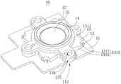
图4是本发明实施方式的指示装置的立体示意图;4 is a schematic perspective view of a pointing device according to an embodiment of the present invention;
图5是本发明实施方式的指示装置的平面示意图;FIG. 5 is a schematic plan view of a pointing device according to an embodiment of the present invention;
图6是沿图5中的指示装置的VI-VI线的截面示意图;6 is a schematic cross-sectional view along line VI-VI of the pointing device in FIG. 5;
图7是图2中的导光件的平面示意图;7 is a schematic plan view of the light guide in FIG. 2;
图8是图3中的导光件的平面示意图;8 is a schematic plan view of the light guide in FIG. 3;
图9是图2中的按键的平面示意图;和Figure 9 is a schematic plan view of the key in Figure 2; and
图10是图3中的按键的平面示意图。FIG. 10 is a schematic plan view of the key in FIG. 3 .
主要元件符号附图说明:Description of main components and symbols:
电池组件100、指示装置10、壳体20、电池30、第一外壳22、操作孔222、第二外壳24、供电接口242、基板11、光源12、导光件13、出光件14、按键15、开关件16、紧固件17、第一结合部112、导光部131、按压部132、阻隔部133、第一注塑槽134、第二结合部135、顶面1311、底面1312和侧面1313、子顶面1314、外侧面1315、内侧面1316、入光面1317、反光面1318、第二注塑槽1332、按键孔142、透光部144、第三结合部146、第一凸台152、第二凸台154、阶梯面1522、第一凹槽1524、凸块1526、第二凹槽1542。
具体实施方式Detailed ways
以下结合附图对本发明的实施方式作进一步说明。附图中相同或类似的标号自始至终表示相同或类似的元件或具有相同或类似功能的元件。The embodiments of the present invention will be further described below with reference to the accompanying drawings. The same or similar reference numbers refer to the same or similar elements or elements having the same or similar functions throughout the drawings.
另外,下面结合附图描述的本发明的实施方式是示例性的,仅用于解释本发明的实施方式,而不能理解为对本发明的限制。In addition, the embodiments of the present invention described below in conjunction with the accompanying drawings are exemplary, and are only used to explain the embodiments of the present invention, and should not be construed as limiting the present invention.
在本发明中,除非另有明确的规定和限定,第一特征在第二特征“上”或“下”可以是第一和第二特征直接接触,或第一和第二特征通过中间媒介间接接触。而且,第一特征在第二特征“之上”、“上方”和“上面”可是第一特征在第二特征正上方或斜上方,或仅仅表示第一特征水平高度高于第二特征。第一特征在第二特征“之下”、“下方”和“下面”可以是第一特征在第二特征正下方或斜下方,或仅仅表示第一特征水平高度小于第二特征。In the present invention, unless otherwise expressly specified and limited, a first feature "on" or "under" a second feature may be in direct contact between the first and second features, or the first and second features indirectly through an intermediary touch. Also, the first feature being "above", "over" and "above" the second feature may mean that the first feature is directly above or obliquely above the second feature, or simply means that the first feature is level higher than the second feature. The first feature being "below", "below" and "below" the second feature may mean that the first feature is directly below or obliquely below the second feature, or simply means that the first feature has a lower level than the second feature.
请参阅图1至图3,本发明实施方式的电池组件100包括指示装置10、壳体20和电池30。电池30安装在壳体20上。指示装置10安装在壳体20上,指示装置10与电池30连接。电池组件100可以运用在无人机、移动终端、头显设备等中,其中无人机可以是无人飞行器、无人车、无人船等,在此不作限制。Referring to FIGS. 1 to 3 , a
具体地,壳体20包括第一外壳22和第二外壳24,第一外壳22和第二外壳24结合形成壳体20,第一外壳22和第二外壳24可以通过卡合、胶合或螺丝固定等方式结合。指示装置10安装在第一外壳22上,第一外壳22开设有操作孔222,操作孔222与指示装置10的位置对应设置,指示装置10穿设操作孔222并从操作孔222暴露以指示电池30的使用状态,其中电池30的使用状态包括电量剩余情况和电源30的供电状态。电池30安装在第二外壳24上,第二外壳24形成有供电接口242。指示装置10与电池30电连接以指示电池30的使用状态。Specifically, the
请参阅图4至图6,本发明的指示装置10包括基板11、光源12和导光件13。光源12设置在基板11上。Referring to FIGS. 4 to 6 , the
导光件13包括导光部131,导光部131形成有顶面1311、底面1312和侧面1313。顶面1311与底面1312相背。侧面1313连接顶面1311与底面1312。侧面1313包括外侧面1315及内侧面1316。底面1312与基板11结合。请参阅图6,光源12用于向外侧面1315发射光线L以射入导光部131,射入导光部131的光线L由内侧面1316反射后从顶面1311射出,以指示电池30的使用状态。The
具体地,光源12和导光件13均设置在基板11上,导光件13和光源12间隔设置。顶面1311与底面1312相背,侧面1313连接顶面1311和底面1312,导光件13的底面1312与基板11结合。外侧面1315与内侧面1316相对。光源12的位置与外侧面1315相对且光源12用于朝外侧面1315发射光线L,光线L经过外侧面1315后进入导光部131内然后经过内侧面1316反射,反射后的光线L朝向顶面1311并从顶面1311射出以指示电池30(图1所示)的使用状态。Specifically, the
本发明实施方式的指示装置10的导光部131的顶面1311和底面1312相背,光源12发射的光线L从外侧面1315射入导光部131后经过内侧面1316反射后从顶面1311射出,避免光源12直接照射并从顶面1311射出从而形成超亮点导致发光不均匀的情况,通过均匀的光线L指示电池30的使用状态,用户体验好。The
导光部131的顶面1311位于内侧面1316上方的部位与底面1312平行,且内侧面1316相对底面1312倾斜45度。因此,在保证光线沿平行于底面1312的方向入射到导光部131内时,经过内侧面1316的反射,可从顶面1311位于内侧面1316上方的部位射出,且在顶面1311的该部位不被折射,减少光的损耗。The portion of the
请参阅图4至图6,指示装置10包括基板11、光源12、导光件13、出光件14、按键15、开关件16和紧固件17(图2所示)。Referring to FIGS. 4 to 6 , the
基板11包括第一结合部112,第一结合部112可用于固定连接基板11、导光件13和出光件14,在本发明实施例中,第一结合部112为通孔。基板11可以是硬质电路板或软硬结合板。如此,基板11可以起到稳定的支撑作用。基板11的形状可以为矩形、凸字形、圆形等等,在此不做限制,只需要能够承载光源12、导光件13、出光件14、按键15、开关件16以及紧固件17即可。The
光源12的数量可以为多个,如两个、三个或四个等等。光源12环绕导光件13间隔设置在基板11上,光源12与基板11电连接。光源12可以是发光二极管(Light-EmittingDiode,LED)灯,LED灯的体积较小,易于实现小型化,且LED灯较为省电,有利于节能。当然,光源12也可以采用其他类型的光源12,在此不做限制。The number of
请结合图7和图8,导光件13包括导光部131、按压部132、阻隔部133、第一注塑槽134和第二结合部135。Please refer to FIG. 7 and FIG. 8 , the
导光部131形成有顶面1311、底面1312和侧面1313。顶面1311与底面1312相背,侧面1313连接顶面1311和底面1312。顶面1311包括多个子顶面1314。导光部131呈环形,可以是圆环、矩形环等等,本发明实施方式的导光部131为圆环。导光部131通过底面1312与基板11结合。The
侧面1313包括外侧面1315和与外侧面1315相背的内侧面1316。光源12与弧面的边缘的连线所覆盖的范围覆盖光源12的照射范围,也即是说,光源12的照射范围被弧面覆盖,光源12发出的光线全都照射在弧面上,从而最大限度的利用光源12发出的光线。在其他实施方式中,入光面1317也可以是其他形状如平面等,只要能覆盖光线的照射范围即可。
反光面1318沿着弧面的两侧延伸,反光面1318上设置有反光膜;或者,反光面1318进行抛光处理;或者,反光面1318既进行抛光处理又设置反光膜。如此,将光源12入射的光线充分反射,防止光线从反光面1318上射出,充分利用光源12的光量。光线经过反光面1318反射后朝向内侧面1316发射,内侧面1316与反光面1318类似,设置有反光膜或进行抛光处理,或者既设置反光膜又进行抛光处理。内侧面1316的倾斜角度与光线的入射方向呈锐角,可以将光线的入射方向改变,使得光线反射向顶面1311以从顶面1311射出,从而指示电池30的使用状态。The
按压部132和阻隔部133连接且采用相同材料制成。按压部132设置在导光部131的环形中部。按压部132可为圆拱形,按压部132与阻隔部133连接且采用相同的材料一体成型,按压部132为弹性元件,例如采用橡胶材料或软胶材料,橡胶或软胶都有一定的弹性,且因为按压部132为圆拱形,在被按压后可自行恢复按压前的状态。The
阻隔部133上开设有第二注塑槽1332。阻隔部133贯穿导光部131并将导光部131的顶面1311分隔成多个子顶面1314,例如可以是两个、三个或四个,子顶面1314的数量根据对电量指示的精确度的要求进行设计。阻隔部133采用不透光的材料,例如橡胶,可以将相邻的子顶面1314分隔开,光线无法在相邻的子顶面1314对应的导光部131之间传播,也就是说,每个子顶面1314对应的导光部131的部分被阻隔部133分隔开,从而每个子顶面1314形成一个单独的发光区域,对应的,指示装置10上与子顶面1314对应的区域被点亮,对电池30的使用状态进行形象的指示。The blocking
每个子顶面1314与至少一个光源12对应,也就是说从每个子顶面1314射出的光来自于至少一个光源12发射的光线,从而保证发光亮度。导光部131与按压部132采用不同的材料,而按压部132与阻隔部133连接且采用相同材料,所以导光部131与按压部132采用了不同的材料,导光部131与阻隔部133也采用了不同的材料,此种导光件13可以通过双色注塑工艺一体成型,导光部131通过向第一注塑槽134注入材料(如熔融态塑料)注塑形成,阻隔部133和按压部132通过向第二注塑槽1332注入材料(如熔融态橡胶)注塑形成,工艺成熟易于实现自动化生产。第二结合部135的位置与第一结合部112的位置对应,第二结合部135为通孔,在如图7的实施例中,通孔开设在第一凸耳上,其中第一凸耳可以自导光部131边缘延伸。Each
出光件14包括按键孔142、透光部144和第三结合部146。出光件14设置在顶面1311上,光线从顶面1311射出后照射出光件14。透光部144环绕按键孔142设置,透光部144为环形,透光部144使用透光材料,如透光率较高的玻璃或者塑料等等。透光部144上形成与子顶面1314数量对应的多个虚拟的透光区域(透光部144实际上并没有划分成多个分隔开的区域,这里为了方便对子顶面1314对应的透光部144区域进行描述,将透光部144划分为多个虚拟的透光区域),因为不同子顶面1314被不透光的阻隔部133分隔开,透光区域会形成与阻隔部133对应的暗部和与子顶面1314对应的亮部。在指示电量的使用情况时,可以根据电池30的电量,对应的光源12发光从而使得对应的子顶面1314射出光线照射出光件14对应的透光区域以发光。如此,可以清楚形象的指示电量。第三结合部146的位置与第二结合部135的位置对应,第三结合部146为通孔,在如图4的实施例中,通孔开设在第二凸耳上,其中第二凸耳可以自透光部144边缘延伸。紧固件17通过第一结合部112、第二结合部135以及第三结合部146将基板11、导光件13和出光件14固定安装在第一壳体22的内壁上。紧固件17为螺钉,当然紧固件17也可以是其他合适的部件,只需与第一结合部112、第二结合部135以及第三结合部146配合可以将基板11、导光件13和出光件14固定安装在第一壳体22的内壁即可。The light-emitting
请结合图9和图10,按键15包括第一凸台152和第二凸台上154。按键15设置在按压部132的与基板11相背的一侧。第二凸台154自第一凸台152的顶面延伸而成。第一凸台152的顶面形成有环绕第二凸台154的阶梯面1522。第一凸台152的底面朝第二凸台154凹陷形成第一凹槽1524,第二凸台154的底面朝第二凸台154的顶面凹陷形成第二凹槽1542,第一凹槽1524环绕第二凹槽1544,第一凹槽1524内形成有自第一凹槽1524边缘向第二凹槽1542延伸的多个凸块1526,多个凸块1526环绕第二凹槽1542设置,凸块1526的数量至少为2个,例如可以为2个、3个、4个或5个等等,本发明实施方式的凸块1526数量为4个,4个凸块1526相配合,可以稳定地承载在按压部132上。凸块1526形状与按压部132的形状相配合,第二凹槽1542及多个凸块1526与按压部132的形状相配合以使按键15承载在按压部132上,在按键15被按压后按压部132均匀受力以产生弹性形变。出光件14承载在按键15上,透光部144的底面抵持在阶梯面1522上,按键15从出光件14的按键孔142露出,按键15在被按压后给按压部132施加均匀的压力使按压部132形变,在通过紧固件17将出光件14和导光件13固定在一起后,透光部144的底面压在阶梯面1522上还可以防止按键15从按键孔142中掉出。Please refer to FIG. 9 and FIG. 10 , the
开关件16设置在基板11上并与按压部132的位置对应,按压部132位于第二凹槽1542的部分承载在开关件16上。开关件16为弹性部件,在被按压产生弹性形变后会恢复形变从而方便用户多次按压。按压部132间隔按键15和开关件16,按压部132也为弹性部件,且材质较软,从而可以对开关件16起到保护作用。按键15被按压后使得按压部132发生弹性形变从而触发开关件16。The
电池组件100可以根据不同触发动作控制指示装置10及电池30中至少一种执行对应的操作。例如,电池组件100根据第一触发动作控制指示装置10的预定数量的光源12发光,以使光线穿过对应的子顶面1314照射透光区域,从而使得对应的透光区域被点亮进而指示电池30的电量使用情况。预定数量与电池30的电量呈正相关,比如第一触发动作为短按,光源12的数量为4个,4个光源12环绕按压部132的中心(开关件16的中心)均匀分布,每个子顶面1314对应一个光源12,此时存在4个透光区域,每个光源12对应一个透光区域。用户短按按键15后,那么在电池30电量为0%至25%时仅有一个光源12发光,也即是说,一个透光区域被点亮;在电池30电量为25%至50%时,有两个光源12发光,即两个透光区域被点亮;在电池30电量为50%至75%时,有3个光源12发光,即3个透光区域被点亮;在电池30电量为75%至100%时,有四个光源12发光,即四个透光区域被点亮。如此,可以形象的指示电量。当然也可以设置更多的光源12对应更多的透光区域(如设置10个光源12,每个光源对应一个透光区域)以对电量进行更准确的指示。可以根据对指示精度的要求和节能的需求来设计。The
又例如,根据第二触发动作控制多个光源12交替发光,并使得对应的透光区域被点亮,例如,第二触发动作为双击,光源12为4个,每个子顶面1314对应一个光源12,在用户双击按键15后,光源12顺时针依次亮起且后一个光源12亮起时前一个熄灭,类似跑马灯效果。For another example, the plurality of
再例如,根据第三触发动作控制电池30通过供电接口242向外部设备供电,比如第三触发动作为先短按再长按,用户在对按键15先短按再长按后,即可控制电池30通过供电接口242向与供电接口242连接的外部设备进行供电。For another example, the
上述第一触发动作、第二触发动作和第三触发动作可以单独触发也可以同时被触发,例如,第一触发动作和第二触发动作相同例如为短按,用户对按键15进行短按后第二触发动作对应的操作先执行,第一触发动作对应的操作后执行,也即是说,按键15被短按后,先实现跑马灯效果,然后根据电池30的电量情况控制对应的光源12发光以指示电量情况,从而比较酷炫的指示电量。当然,不限于上述提到的第一至第三触发动作,还可以有第四触发动作如长按,用于控制电池30停止向外部设备供电。指示装置10在未接受到触发动作是保持休眠,也即是说,保持光源12不发光。如此,可以节省电量。在其他实施方式中,指示装置10也可以一直点亮用于指示电池30的电量使用情况,用户无需主动通过触发动作去控制指示装置10指示电量的使用情况,用户体验较好。The above-mentioned first triggering action, second triggering action and third triggering action can be triggered independently or simultaneously. For example, the first triggering action and the second triggering action are the same, for example, a short press. The operation corresponding to the second trigger action is executed first, and the operation corresponding to the first trigger action is executed after that. That is to say, after the
综上,本发明实施方式的指示装置10的导光部131的顶面1311和底面1312相背,光源12为多个且光源12与入光面1317对准,光源12用于朝入光面1317发射光线,光线从入光面1317进入导光部131后,再经过反光面1318和内侧面1316反射,从与光源12对应的子顶面1314射出。不同的子顶面1314被不透光的阻隔部133分隔开,从不同的子顶面1314射出的光线照射对应的透光区域以点亮该透光区域,相邻的透光区域通过与阻隔部133对应的暗部分隔开,然后根据电池30使用状态控制预定数量的光源12发光以点亮对应的透光区域从而指示电池30的使用状态。避免了光源12直接照射子顶面1314而使得对应的透光区域出现超亮点导致亮度分布不均匀,影响用户体验。To sum up, the
在某些实施方式中,光源12为一个,光源12可以发出不同颜色的光,光源12与整个顶面1311对应(即该一个光源12发出的光从整个顶面1311射出),光源12发光时光线从顶面1311射出以点亮整个透光部144,光源12通过不同电量百分比对应不同的颜色来指示电量。In some embodiments, the
具体地,光源12为一个且可以发出多种不同颜色的光,例如光源12可以发出四种颜色(绿、蓝、黄、红)的光,绿光表示电池30的电量在75%至100%,蓝光表示电池30的电量在50%至75%,黄光表示电池30的电量在25%至50%,红光表示电池30的电量在0%至25%。如此,既可以保证透光部144发光均匀,而且仅用一个光源12,较为节省电量。另外,通过不同的颜色指示电量,较为简单直观,用户体验好。Specifically, the
在本说明书的描述中,参考术语“某些实施方式”、“一个实施方式”、“一些实施方式”、“示例”、“具体示例”、或“一些示例”等的描述意指结合该实施例或示例描述的具体特征、结构、材料或者特点包含于本发明的至少一个实施例或示例中。在本说明书中,对上述术语的示意性表述不必须针对的是相同的实施例或示例。而且,描述的具体特征、结构、材料或者特点可以在任一个或多个实施例或示例中以合适的方式结合。此外,在不相互矛盾的情况下,本领域的技术人员可以将本说明书中描述的不同实施例或示例以及不同实施例或示例的特征进行结合和组合。In the description of this specification, reference to the terms "some embodiments", "one embodiment", "some embodiments", "example", "specific example", or "some examples" or the like is meant to be combined with the description of the embodiment A particular feature, structure, material, or characteristic described by an example or example is included in at least one embodiment or example of the present invention. In this specification, schematic representations of the above terms are not necessarily directed to the same embodiment or example. Furthermore, the particular features, structures, materials or characteristics described may be combined in any suitable manner in any one or more embodiments or examples. Furthermore, those skilled in the art may combine and combine the different embodiments or examples described in this specification, as well as the features of the different embodiments or examples, without conflicting each other.
此外,术语“第一”、“第二”仅用于描述目的,而不能理解为指示或暗示相对重要性或者隐含指明所指示的技术特征的数量。由此,限定有“第一”、“第二”的特征可以明示或者隐含地包括至少一个所述特征。在本发明的描述中,“多个”的含义是至少两个,例如两个,三个,除非另有明确具体的限定。In addition, the terms "first" and "second" are only used for descriptive purposes, and should not be construed as indicating or implying relative importance or implying the number of indicated technical features. Thus, features delimited with "first", "second" may expressly or implicitly include at least one of said features. In the description of the present invention, "plurality" means at least two, such as two, three, unless expressly and specifically defined otherwise.
尽管上面已经示出和描述了本发明的实施例,可以理解的是,上述实施例是示例性的,不能理解为对本发明的限制,本领域的普通技术人员在本发明的范围内可以对上述实施例进行变化、修改、替换和变型,本发明的范围由权利要求及其等同物限定。Although the embodiments of the present invention have been shown and described above, it should be understood that the above-mentioned embodiments are exemplary and should not be construed as limiting the present invention. Embodiments are subject to changes, modifications, substitutions and alterations, and the scope of the present invention is defined by the claims and their equivalents.
Claims (39)
Applications Claiming Priority (1)
| Application Number | Priority Date | Filing Date | Title |
|---|---|---|---|
| PCT/CN2018/092939WO2020000210A1 (en) | 2018-06-26 | 2018-06-26 | Indication device and battery assembly |
Publications (2)
| Publication Number | Publication Date |
|---|---|
| CN110678918A CN110678918A (en) | 2020-01-10 |
| CN110678918Btrue CN110678918B (en) | 2022-06-24 |
Family
ID=68985645
Family Applications (1)
| Application Number | Title | Priority Date | Filing Date |
|---|---|---|---|
| CN201880013243.5AExpired - Fee RelatedCN110678918B (en) | 2018-06-26 | 2018-06-26 | Indicating device and battery pack |
Country Status (3)
| Country | Link |
|---|---|
| US (1) | US20210104786A1 (en) |
| CN (1) | CN110678918B (en) |
| WO (1) | WO2020000210A1 (en) |
Families Citing this family (4)
| Publication number | Priority date | Publication date | Assignee | Title |
|---|---|---|---|---|
| USD938346S1 (en)* | 2019-05-15 | 2021-12-14 | Harley-Davidson Motor Company Group, LLC | Electric vehicle battery |
| CN112490038A (en)* | 2020-10-30 | 2021-03-12 | 深圳市吉迩科技有限公司 | Key light guide device and method and aerosol generating device |
| CN112662237B (en)* | 2020-11-26 | 2022-05-27 | 浙江南都电源动力股份有限公司 | Temperature sensing color-changing coating and high-temperature early warning battery module |
| CN115400803B (en)* | 2022-09-20 | 2023-06-30 | 江苏拓米洛高端装备股份有限公司 | A battery test box |
Citations (7)
| Publication number | Priority date | Publication date | Assignee | Title |
|---|---|---|---|---|
| JP2008047334A (en)* | 2006-08-11 | 2008-02-28 | Canon Inc | Switch operating member and switch device |
| CN101493543A (en)* | 2008-01-17 | 2009-07-29 | 蒂雅克股份有限公司 | Ring shaped light guide and electronic equipment with the same |
| EP0962694B1 (en)* | 1998-06-05 | 2009-09-09 | Citizen Electronics Co., Ltd. | Planar light source unit |
| CN104380414A (en)* | 2012-05-31 | 2015-02-25 | 矢崎总业株式会社 | Illumination display switching device |
| CN204796735U (en)* | 2013-04-07 | 2015-11-25 | 惠州市吉瑞科技有限公司 | Cigarette case, LED leaded light spare and box body of electron cigarette |
| CN205048369U (en)* | 2015-10-16 | 2016-02-24 | 深圳市卡格尔数码科技有限公司 | A graphical taste modulated structure for battery indicator |
| CN106764683A (en)* | 2016-12-23 | 2017-05-31 | 惠州华阳通用电子有限公司 | A kind of knob light guiding ring structure and its light control method |
Family Cites Families (8)
| Publication number | Priority date | Publication date | Assignee | Title |
|---|---|---|---|---|
| JP2004327392A (en)* | 2003-04-28 | 2004-11-18 | Sharp Corp | Lighting equipment |
| CN100436197C (en)* | 2003-07-19 | 2008-11-26 | 鸿富锦精密工业(深圳)有限公司 | Light guiding device and luminous sign object |
| JP2006236853A (en)* | 2005-02-25 | 2006-09-07 | Sumitomo Wiring Syst Ltd | Light guide and lighting system equipped with light guide |
| CN1838086A (en)* | 2005-03-24 | 2006-09-27 | 华硕电脑股份有限公司 | Notebook computer with battery status indicator |
| CN104566127A (en)* | 2014-12-18 | 2015-04-29 | 南京化工职业技术学院 | Detachable LED (Light Emitting Diode) firefighting lamp |
| TWI553683B (en)* | 2015-07-03 | 2016-10-11 | 致伸科技股份有限公司 | Luminous keyboard |
| US9971084B2 (en)* | 2015-09-28 | 2018-05-15 | Apple Inc. | Illumination structure for uniform illumination of keys |
| CN205901823U (en)* | 2016-06-28 | 2017-01-18 | 厦门美图移动科技有限公司 | Main screen button can show battery power's mobile terminal |
- 2018
- 2018-06-26CNCN201880013243.5Apatent/CN110678918B/ennot_activeExpired - Fee Related
- 2018-06-26WOPCT/CN2018/092939patent/WO2020000210A1/ennot_activeCeased
- 2020
- 2020-12-17USUS17/125,127patent/US20210104786A1/ennot_activeAbandoned
Patent Citations (7)
| Publication number | Priority date | Publication date | Assignee | Title |
|---|---|---|---|---|
| EP0962694B1 (en)* | 1998-06-05 | 2009-09-09 | Citizen Electronics Co., Ltd. | Planar light source unit |
| JP2008047334A (en)* | 2006-08-11 | 2008-02-28 | Canon Inc | Switch operating member and switch device |
| CN101493543A (en)* | 2008-01-17 | 2009-07-29 | 蒂雅克股份有限公司 | Ring shaped light guide and electronic equipment with the same |
| CN104380414A (en)* | 2012-05-31 | 2015-02-25 | 矢崎总业株式会社 | Illumination display switching device |
| CN204796735U (en)* | 2013-04-07 | 2015-11-25 | 惠州市吉瑞科技有限公司 | Cigarette case, LED leaded light spare and box body of electron cigarette |
| CN205048369U (en)* | 2015-10-16 | 2016-02-24 | 深圳市卡格尔数码科技有限公司 | A graphical taste modulated structure for battery indicator |
| CN106764683A (en)* | 2016-12-23 | 2017-05-31 | 惠州华阳通用电子有限公司 | A kind of knob light guiding ring structure and its light control method |
Also Published As
| Publication number | Publication date |
|---|---|
| CN110678918A (en) | 2020-01-10 |
| US20210104786A1 (en) | 2021-04-08 |
| WO2020000210A1 (en) | 2020-01-02 |
Similar Documents
| Publication | Publication Date | Title |
|---|---|---|
| CN110678918B (en) | Indicating device and battery pack | |
| US8366292B2 (en) | Plural color lighting device | |
| CN100513863C (en) | The luminous device using light emitting diodes | |
| EP2853942A1 (en) | Luminescent light emitting device having luminescent material plate that is caused to be luminous by excitation light source and projector including same luminescent light emitting device | |
| US20090168441A1 (en) | Illumination device and car with same | |
| US8366293B2 (en) | Color changing lighting device | |
| TWM454144U (en) | Light emitting cosmetic mirror | |
| KR101440476B1 (en) | Optical element and illuminant device using the same | |
| CN116892692A (en) | Dual-power source light source | |
| WO2016112843A1 (en) | Light-emitting keyboard switch | |
| CN219867641U (en) | Double-light source flashlight | |
| CN201327787Y (en) | Key light guide structure | |
| WO2022089125A1 (en) | Button light guide apparatus and method, and aerosol generating apparatus | |
| CN220154798U (en) | Refractive pointer luminous clock | |
| CN208444567U (en) | Instruction device and battery component | |
| CN112530725A (en) | Key assembly and cleaning robot | |
| CN208738097U (en) | Luminous key structure | |
| JP5914817B2 (en) | Lighting device | |
| KR101032885B1 (en) | Bicycle lighting | |
| US20060096406A1 (en) | Gear lever having a light emitting effect | |
| CN220911201U (en) | Light emitting device and vehicle | |
| CN112942988A (en) | Remote control key | |
| CN109282237B (en) | Lamp and lighting control method thereof | |
| CN215212823U (en) | Remote control key | |
| CN221975193U (en) | Bulb |
Legal Events
| Date | Code | Title | Description |
|---|---|---|---|
| PB01 | Publication | ||
| PB01 | Publication | ||
| SE01 | Entry into force of request for substantive examination | ||
| SE01 | Entry into force of request for substantive examination | ||
| GR01 | Patent grant | ||
| GR01 | Patent grant | ||
| CF01 | Termination of patent right due to non-payment of annual fee | ||
| CF01 | Termination of patent right due to non-payment of annual fee | Granted publication date:20220624 |