CN110673308A - Optical imaging system - Google Patents
Optical imaging systemDownload PDFInfo
- Publication number
- CN110673308A CN110673308ACN201911071488.6ACN201911071488ACN110673308ACN 110673308 ACN110673308 ACN 110673308ACN 201911071488 ACN201911071488 ACN 201911071488ACN 110673308 ACN110673308 ACN 110673308A
- Authority
- CN
- China
- Prior art keywords
- lens
- imaging system
- optical imaging
- optical
- image
- Prior art date
- Legal status (The legal status is an assumption and is not a legal conclusion. Google has not performed a legal analysis and makes no representation as to the accuracy of the status listed.)
- Granted
Links
Images


Classifications
- G—PHYSICS
- G02—OPTICS
- G02B—OPTICAL ELEMENTS, SYSTEMS OR APPARATUS
- G02B9/00—Optical objectives characterised both by the number of the components and their arrangements according to their sign, i.e. + or -
- G02B9/64—Optical objectives characterised both by the number of the components and their arrangements according to their sign, i.e. + or - having more than six components
- G—PHYSICS
- G02—OPTICS
- G02B—OPTICAL ELEMENTS, SYSTEMS OR APPARATUS
- G02B13/00—Optical objectives specially designed for the purposes specified below
- G02B13/001—Miniaturised objectives for electronic devices, e.g. portable telephones, webcams, PDAs, small digital cameras
- G02B13/0015—Miniaturised objectives for electronic devices, e.g. portable telephones, webcams, PDAs, small digital cameras characterised by the lens design
- G02B13/002—Miniaturised objectives for electronic devices, e.g. portable telephones, webcams, PDAs, small digital cameras characterised by the lens design having at least one aspherical surface
- G02B13/0045—Miniaturised objectives for electronic devices, e.g. portable telephones, webcams, PDAs, small digital cameras characterised by the lens design having at least one aspherical surface having five or more lenses
- G—PHYSICS
- G02—OPTICS
- G02B—OPTICAL ELEMENTS, SYSTEMS OR APPARATUS
- G02B13/00—Optical objectives specially designed for the purposes specified below
- G02B13/06—Panoramic objectives; So-called "sky lenses" including panoramic objectives having reflecting surfaces
- G—PHYSICS
- G02—OPTICS
- G02B—OPTICAL ELEMENTS, SYSTEMS OR APPARATUS
- G02B13/00—Optical objectives specially designed for the purposes specified below
- G02B13/18—Optical objectives specially designed for the purposes specified below with lenses having one or more non-spherical faces, e.g. for reducing geometrical aberration
- G—PHYSICS
- G02—OPTICS
- G02B—OPTICAL ELEMENTS, SYSTEMS OR APPARATUS
- G02B27/00—Optical systems or apparatus not provided for by any of the groups G02B1/00 - G02B26/00, G02B30/00
- G02B27/0025—Optical systems or apparatus not provided for by any of the groups G02B1/00 - G02B26/00, G02B30/00 for optical correction, e.g. distorsion, aberration
Landscapes
- Physics & Mathematics (AREA)
- General Physics & Mathematics (AREA)
- Optics & Photonics (AREA)
- Lenses (AREA)
Abstract
Description
Translated fromChinese技术领域technical field
本申请涉及光学元件领域,更具体地,涉及一种光学成像系统。The present application relates to the field of optical components, and more particularly, to an optical imaging system.
背景技术Background technique
近年来,随着便携式电子产品的升级换代,市场对适用于便携式电子产品的光学成像系统的需求逐渐增加。例如手机背部的摄像模组通常升级为多摄摄像模组,多摄摄像模组中可包括两套、三套或者更多套光学成像系统。每套光学成像系统侧重不同的光学性能,但其中通常有一套光学成像系统作为主摄。In recent years, with the upgrading of portable electronic products, the market demand for optical imaging systems suitable for portable electronic products has gradually increased. For example, the camera module on the back of the mobile phone is usually upgraded to a multi-camera camera module, and the multi-camera camera module may include two, three or more sets of optical imaging systems. Each optical imaging system focuses on different optical performance, but there is usually one optical imaging system as the main camera.
便携式电子产品上图像软件功能、视频软件功能不断发展,使得手机等电子产品上可以应用更好光学性能的光学成像系统。但手机等便携式电子产品的体积较小,因此较难设计高性能的光学成像系统。而且光学成像系统的透镜数目增加时,会进一步提升设计难度。With the continuous development of image software functions and video software functions on portable electronic products, optical imaging systems with better optical performance can be applied to electronic products such as mobile phones. However, the small size of portable electronic products such as mobile phones makes it difficult to design high-performance optical imaging systems. Moreover, when the number of lenses of the optical imaging system increases, the design difficulty will be further increased.
为了满足小型化需求并满足成像要求,需要一种能够兼顾小型化和大像面、大广角、大孔径的光学成像系统。In order to meet the requirements of miniaturization and imaging requirements, an optical imaging system that can take into account the miniaturization and large image area, large wide angle, and large aperture is required.
发明内容SUMMARY OF THE INVENTION
本申请提供了可适用于便携式电子产品的、可至少解决或部分解决现有技术中的上述至少一个缺点的光学成像系统。The present application provides an optical imaging system applicable to portable electronic products that addresses at least or partially addresses at least one of the above-mentioned disadvantages of the prior art.
本申请提供了一种光学成像系统,其沿光轴由物侧至像侧依序包括:具有光焦度的第一透镜;具有负光焦度的第二透镜;具有光焦度的第三透镜;具有正光焦度的第四透镜;具有光焦度的第五透镜;具有光焦度的第六透镜;以及具有光焦度的第七透镜,其物侧面可为凹面,像侧面可为凹面。The present application provides an optical imaging system, which includes sequentially from the object side to the image side along the optical axis: a first lens with optical power; a second lens with negative optical power; a third lens with optical power lens; a fourth lens with positive power; a fifth lens with power; a sixth lens with power; and a seventh lens with power, the object side can be concave, and the image side can be Concave.
在一个实施方式中,光学成像系统的成像面上有效像素区域的对角线长的一半ImgH可满足ImgH>6.0mm。In one embodiment, the half ImgH of the diagonal length of the effective pixel area on the imaging surface of the optical imaging system may satisfy ImgH>6.0 mm.
在一个实施方式中,第一透镜的物侧面至成像面在光轴上的间隔距离TTL与光学成像系统的入瞳直径EPD可满足TTL/EPD<2.5。In one embodiment, the separation distance TTL between the object side of the first lens and the imaging surface on the optical axis and the entrance pupil diameter EPD of the optical imaging system may satisfy TTL/EPD<2.5.
在一个实施方式中,光学成像系统的总有效焦距f与第六透镜的有效焦距f6可满足1.15<f6/f<1.65。In one embodiment, the total effective focal length f of the optical imaging system and the effective focal length f6 of the sixth lens may satisfy 1.15<f6/f<1.65.
在一个实施方式中,第一透镜的有效焦距f1与第六透镜的有效焦距f6可满足1.3<f6/f1<1.7。In one embodiment, the effective focal length f1 of the first lens and the effective focal length f6 of the sixth lens may satisfy 1.3<f6/f1<1.7.
在一个实施方式中,第四透镜的像侧面和光轴的交点至第四透镜的像侧面的有效半径顶点的轴上距离SAG42与第五透镜的物侧面和光轴的交点至第五透镜的物侧面的有效半径顶点的轴上距离SAG51可满足1.2<SAG51/SAG42<2.5。In one embodiment, the on-axis distance SAG42 from the intersection of the image side surface and the optical axis of the fourth lens to the apex of the effective radius of the image side surface of the fourth lens and the intersection of the object side surface and the optical axis of the fifth lens to the object side surface of the fifth lens The on-axis distance SAG51 of the effective radius vertex can satisfy 1.2<SAG51/SAG42<2.5.
在一个实施方式中,第二透镜的物侧面的曲率半径R3与光学成像系统的总有效焦距f可满足1.3<R3/f<3。In one embodiment, the curvature radius R3 of the object side surface of the second lens and the total effective focal length f of the optical imaging system may satisfy 1.3<R3/f<3.
在一个实施方式中,第三透镜和第四透镜在光轴上的间隔距离T34与第六透镜的边缘厚度ET6可满足0.2<T34/ET6<0.6。In one embodiment, the separation distance T34 between the third lens and the fourth lens on the optical axis and the edge thickness ET6 of the sixth lens may satisfy 0.2<T34/ET6<0.6.
在一个实施方式中,第五透镜的物侧面的曲率半径R9与第五透镜的像侧面的曲率半径R10可满足1.5<(R9+R10)/R10<2.3。In one embodiment, the curvature radius R9 of the object side surface of the fifth lens and the curvature radius R10 of the image side surface of the fifth lens may satisfy 1.5<(R9+R10)/R10<2.3.
在一个实施方式中,第一透镜的有效焦距f1与第二透镜的有效焦距f2可满足-6.0<f2/f1<-2.5。In one embodiment, the effective focal length f1 of the first lens and the effective focal length f2 of the second lens may satisfy -6.0<f2/f1<-2.5.
在一个实施方式中,光学成像系统的总有效焦距f与光学成像系统的入瞳直径EPD可满足f/EPD<1.9。In one embodiment, the total effective focal length f of the optical imaging system and the entrance pupil diameter EPD of the optical imaging system may satisfy f/EPD<1.9.
在一个实施方式中,光学成像系统的成像面上有效像素区域的对角线长的一半ImgH与第一透镜的物侧面至成像面在光轴上的间隔距离TTL可满足TTL/ImgH<1.2。In one embodiment, the distance TTL, which is half the diagonal length of the effective pixel area on the imaging surface of the optical imaging system, ImgH, and the distance TTL between the object side of the first lens and the imaging surface on the optical axis can satisfy TTL/ImgH<1.2.
在一个实施方式中,第一透镜至第三透镜的组合焦距f123与光学成像系统的总有效焦距f可满足1.0<f123/f<1.5。In one embodiment, the combined focal length f123 of the first lens to the third lens and the total effective focal length f of the optical imaging system may satisfy 1.0<f123/f<1.5.
在一个实施方式中,第六透镜的物侧面和光轴的交点至第六透镜的物侧面的有效半径顶点的轴上距离SAG61、第六透镜的像侧面和光轴的交点至第六透镜的像侧面的有效半径顶点的轴上距离SAG62以及第七透镜的物侧面和光轴的交点至第七透镜的物侧面的有效半径顶点的轴上距离SAG71可满足-4<SAG61/(SAG62-SAG71)<-1。In one embodiment, the on-axis distance SAG61 from the intersection of the object side and the optical axis of the sixth lens to the vertex of the effective radius of the sixth lens, the intersection of the image side and the optical axis of the sixth lens to the image side of the sixth lens The on-axis distance SAG62 of the effective radius vertex and the on-axis distance SAG71 from the intersection of the object side and the optical axis of the seventh lens to the effective radius vertex of the seventh lens can satisfy -4<SAG61/(SAG62-SAG71)<- 1.
在一个实施方式中,第二透镜和第三透镜在光轴上的间隔距离T23与第三透镜和第四透镜在光轴上的间隔距离T34可满足1.7<T23/T34<3.7。In one embodiment, the separation distance T23 between the second lens and the third lens on the optical axis and the separation distance T34 between the third lens and the fourth lens on the optical axis may satisfy 1.7<T23/T34<3.7.
在一个实施方式中,第五透镜的物侧面可为凸面。In one embodiment, the object side of the fifth lens may be convex.
在一个实施方式中,第六透镜的物侧面可为凸面。In one embodiment, the object side of the sixth lens may be convex.
本申请采用了七片透镜,通过合理分配各透镜的光焦度、面型、各透镜的中心厚度以及各透镜之间的轴上间距等,使得上述光学成像系统具有小型化和大像面、大广角、大孔径等至少一个有益效果。Seven lenses are used in the present application, and the above optical imaging system has miniaturization, large image surface, At least one beneficial effect of large wide angle, large aperture and the like.
附图说明Description of drawings
结合附图,通过以下非限制性实施方式的详细描述,本申请的其他特征、目的和优点将变得更加明显。在附图中:Other features, objects and advantages of the present application will become more apparent from the following detailed description of non-limiting embodiments in conjunction with the accompanying drawings. In the attached image:
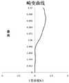
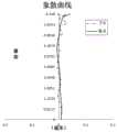
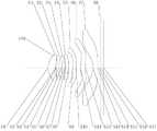
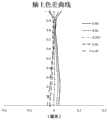
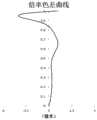
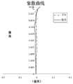
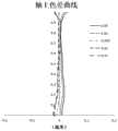
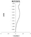
图1示出了根据本申请实施例1的光学成像系统的结构示意图;图2A至图2D分别示出了实施例1的光学成像系统的轴上色差曲线、象散曲线、畸变曲线以及倍率色差曲线;1 shows a schematic structural diagram of an optical imaging system according to
图3示出了根据本申请实施例2的光学成像系统的结构示意图;图4A至图4D分别示出了实施例2的光学成像系统的轴上色差曲线、象散曲线、畸变曲线以及倍率色差曲线;3 shows a schematic structural diagram of the optical imaging system according to Embodiment 2 of the present application; FIGS. 4A to 4D respectively show the on-axis chromatic aberration curve, astigmatism curve, distortion curve and magnification chromatic aberration of the optical imaging system of Embodiment 2 curve;
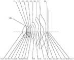
图5示出了根据本申请实施例3的光学成像系统的结构示意图;图6A至图6D分别示出了实施例3的光学成像系统的轴上色差曲线、象散曲线、畸变曲线以及倍率色差曲线;5 shows a schematic structural diagram of the optical imaging system according to Embodiment 3 of the present application; FIGS. 6A to 6D respectively show the axial chromatic aberration curve, astigmatism curve, distortion curve and magnification chromatic aberration of the optical imaging system of Embodiment 3 curve;
图7示出了根据本申请实施例4的光学成像系统的结构示意图;图8A至图8D分别示出了实施例4的光学成像系统的轴上色差曲线、象散曲线、畸变曲线以及倍率色差曲线;7 shows a schematic structural diagram of the optical imaging system according to Embodiment 4 of the present application; FIGS. 8A to 8D respectively show the axial chromatic aberration curve, astigmatism curve, distortion curve and magnification chromatic aberration of the optical imaging system of Embodiment 4 curve;
图9示出了根据本申请实施例5的光学成像系统的结构示意图;图10A至图10D分别示出了实施例5的光学成像系统的轴上色差曲线、象散曲线、畸变曲线以及倍率色差曲线;9 shows a schematic diagram of the structure of the optical imaging system according to
图11示出了根据本申请实施例6的光学成像系统的结构示意图;图12A至图12D分别示出了实施例6的光学成像系统的轴上色差曲线、象散曲线、畸变曲线以及倍率色差曲线;11 shows a schematic structural diagram of the optical imaging system according to Embodiment 6 of the present application; FIGS. 12A to 12D respectively show the axial chromatic aberration curve, astigmatism curve, distortion curve and magnification chromatic aberration of the optical imaging system of Embodiment 6 curve;
图13示出了根据本申请实施例7的光学成像系统的结构示意图;图14A至图14D分别示出了实施例7的光学成像系统的轴上色差曲线、象散曲线、畸变曲线以及倍率色差曲线;13 shows a schematic structural diagram of the optical imaging system according to Embodiment 7 of the present application; FIGS. 14A to 14D respectively show the on-axis chromatic aberration curve, astigmatism curve, distortion curve and magnification chromatic aberration of the optical imaging system of Embodiment 7 curve;
图15示出了根据本申请实施例8的光学成像系统的结构示意图;图16A至图16D分别示出了实施例8的光学成像系统的轴上色差曲线、象散曲线、畸变曲线以及倍率色差曲线。15 shows a schematic structural diagram of the optical imaging system according to Embodiment 8 of the present application; FIGS. 16A to 16D respectively show the on-axis chromatic aberration curve, astigmatism curve, distortion curve and magnification chromatic aberration of the optical imaging system of Embodiment 8 curve.
具体实施方式Detailed ways
为了更好地理解本申请,将参考附图对本申请的各个方面做出更详细的说明。应理解,这些详细说明只是对本申请的示例性实施方式的描述,而非以任何方式限制本申请的范围。在说明书全文中,相同的附图标号指代相同的元件。表述“和/或”包括相关联的所列项目中的一个或多个的任何和全部组合。For a better understanding of the present application, various aspects of the present application will be described in more detail with reference to the accompanying drawings. It should be understood that these detailed descriptions are merely illustrative of exemplary embodiments of the present application and are not intended to limit the scope of the present application in any way. Throughout the specification, the same reference numerals refer to the same elements. The expression "and/or" includes any and all combinations of one or more of the associated listed items.
应注意,在本说明书中,第一、第二、第三等的表述仅用于将一个特征与另一个特征区分开来,而不表示对特征的任何限制。因此,在不背离本申请的教导的情况下,下文中讨论的第一透镜也可被称作第二透镜或第三透镜。It should be noted that in this specification, the expressions first, second, third etc. are only used to distinguish one feature from another feature and do not imply any limitation on the feature. Accordingly, the first lens discussed below may also be referred to as a second lens or a third lens without departing from the teachings of the present application.
在附图中,为了便于说明,已稍微夸大了透镜的厚度、尺寸和形状。具体来讲,附图中所示的球面或非球面的形状通过示例的方式示出。即,球面或非球面的形状不限于附图中示出的球面或非球面的形状。附图仅为示例而并非严格按比例绘制。In the drawings, the thickness, size and shape of the lenses have been slightly exaggerated for convenience of explanation. In particular, the spherical or aspherical shapes shown in the figures are shown by way of example. That is, the shape of the spherical or aspherical surface is not limited to the shape of the spherical or aspherical surface shown in the drawings. The drawings are examples only and are not drawn strictly to scale.
在本文中,近轴区域是指光轴附近的区域。若透镜表面为凸面且未界定该凸面位置时,则表示该透镜表面至少于近轴区域为凸面;若透镜表面为凹面且未界定该凹面位置时,则表示该透镜表面至少于近轴区域为凹面。每个透镜最靠近被摄物体的表面称为该透镜的物侧面,每个透镜最靠近成像面的表面称为该透镜的像侧面。Herein, the paraxial region refers to the region near the optical axis. If the lens surface is convex and the convex position is not defined, it means that the lens surface is convex at least in the paraxial region; if the lens surface is concave and the concave position is not defined, it means that the lens surface is at least in the paraxial region. Concave. The surface of each lens closest to the object is called the object side of the lens, and the surface of each lens closest to the imaging surface is called the image side of the lens.
还应理解的是,用语“包括”、“包括有”、“具有”、“包含”和/或“包含有”,当在本说明书中使用时表示存在所陈述的特征、元件和/或部件,但不排除存在或附加有一个或多个其它特征、元件、部件和/或它们的组合。此外,当诸如“...中的至少一个”的表述出现在所列特征的列表之后时,修饰整个所列特征,而不是修饰列表中的单独元件。此外,当描述本申请的实施方式时,使用“可”表示“本申请的一个或多个实施方式”。并且,用语“示例性的”旨在指代示例或举例说明。It will also be understood that the terms "comprising", "comprising", "having", "comprising" and/or "comprising" when used in this specification mean that the stated features, elements and/or components are present , but does not preclude the presence or addition of one or more other features, elements, components and/or combinations thereof. Furthermore, when an expression such as "at least one of" appears after a list of listed features, it modifies the entire listed feature and not the individual elements of the list. Furthermore, when describing embodiments of the present application, the use of "may" means "one or more embodiments of the present application." Also, the term "exemplary" is intended to refer to an example or illustration.
除非另外限定,否则本文中使用的所有用语(包括技术用语和科学用语)均具有与本申请所属领域普通技术人员的通常理解相同的含义。还应理解的是,用语(例如在常用词典中定义的用语)应被解释为具有与它们在相关技术的上下文中的含义一致的含义,并且将不被以理想化或过度正式意义解释,除非本文中明确如此限定。Unless otherwise defined, all terms (including technical and scientific terms) used herein have the same meaning as commonly understood by one of ordinary skill in the art to which this application belongs. It should also be understood that terms (such as those defined in commonly used dictionaries) should be interpreted to have meanings consistent with their meanings in the context of the related art, and will not be interpreted in an idealized or overly formal sense unless It is expressly so limited herein.
需要说明的是,在不冲突的情况下,本申请中的实施例及实施例中的特征可以相互组合。下面将参考附图并结合实施例来详细说明本申请。It should be noted that the embodiments in the present application and the features of the embodiments may be combined with each other in the case of no conflict. The present application will be described in detail below with reference to the accompanying drawings and in conjunction with the embodiments.
以下对本申请的特征、原理和其他方面进行详细描述。The features, principles, and other aspects of the present application are described in detail below.
根据本申请示例性实施方式的光学成像系统可包括例如七片具有光焦度的透镜,即,第一透镜、第二透镜、第三透镜、第四透镜、第五透镜、第六透镜和第七透镜。这七片透镜沿着光轴由物侧至像侧依序排列。在第一透镜至第七透镜中,任意相邻两透镜之间均可具有空气间隔。The optical imaging system according to the exemplary embodiment of the present application may include, for example, seven lenses having optical power, ie, a first lens, a second lens, a third lens, a fourth lens, a fifth lens, a sixth lens, and a third lens Seven lenses. The seven lenses are arranged in sequence from the object side to the image side along the optical axis. In the first lens to the seventh lens, any two adjacent lenses may have an air space between them.
在示例性实施方式中,第一透镜具有正光焦度或负光焦度;第二透镜可具有负光焦度;第三透镜具有正光焦度或负光焦度;第四透镜可具有正光焦度;第五透镜具有正光焦度或负光焦度;第六透镜具有正光焦度或负光焦度;第七透镜具有正光焦度或负光焦度,其物侧面为凹面,像侧面为凹面。通过控制光学成像系统的各个组元的光焦度的正负分配和镜片面型曲率,来有效的平衡控制系统的低阶像差。In an exemplary embodiment, the first lens may have positive or negative power; the second lens may have negative power; the third lens may have positive or negative power; and the fourth lens may have positive power The fifth lens has positive power or negative power; the sixth lens has positive power or negative power; the seventh lens has positive power or negative power, and its object side is concave and its image side is Concave. By controlling the positive and negative distribution of the power of each component of the optical imaging system and the curvature of the lens surface, the low-order aberrations of the control system can be effectively balanced.
在示例性实施方式中,第五透镜的物侧面可为凸面。示例性地,第六透镜的物侧面可为凸面。通过控制各透镜的面型,有利于降低光学成像系统对公差的敏感性,进而有利于维持光学成像系统的小型化。In an exemplary embodiment, the object side of the fifth lens may be convex. Exemplarily, the object side of the sixth lens may be convex. By controlling the surface shape of each lens, the sensitivity of the optical imaging system to tolerances is reduced, and the miniaturization of the optical imaging system is further maintained.
在示例性实施方式中,本申请的光学成像系统可满足条件式:TTL/ImgH<1.2,其中,ImgH是光学成像系统的成像面上有效像素区域的对角线长的一半,TTL是第一透镜的物侧面至光学成像系统的成像面在光轴上的间隔距离。在示例性实施方式中,本申请的光学成像系统可满足条件式:ImgH>6.0mm。更具体地,光学成像系统可满足6.0mm<ImgH<6.2mm,以及1.15<TTL/ImgH<1.19。在控制光学成像系统的各镜片的面型和光焦度的基础上,通过控制光学成像系统的像高和光学总长,有利于使光学成像系统的结构紧凑、尺寸小,并具有高像素的特点。In an exemplary embodiment, the optical imaging system of the present application can satisfy the conditional formula: TTL/ImgH<1.2, where ImgH is half the diagonal length of the effective pixel area on the imaging plane of the optical imaging system, and TTL is the first The distance between the object side of the lens and the imaging plane of the optical imaging system on the optical axis. In an exemplary embodiment, the optical imaging system of the present application may satisfy the conditional formula: ImgH>6.0mm. More specifically, the optical imaging system may satisfy 6.0mm<ImgH<6.2mm, and 1.15<TTL/ImgH<1.19. On the basis of controlling the surface shape and focal power of each lens of the optical imaging system, by controlling the image height and optical total length of the optical imaging system, it is beneficial to make the optical imaging system compact in structure, small in size, and have the characteristics of high pixels.
在示例性实施方式中,本申请的光学成像系统可满足条件式1.15<f6/f<1.65,其中,f是光学成像系统的总有效焦距,f6是第六透镜的有效焦距。更具体地,f与f6可满足1.18<f6/f<1.60。通过约束第六透镜的有效焦距与总有效焦距的比值,有利于约束光学成像系统的场曲,进而使光学成像系统具有较好的解像力。In an exemplary embodiment, the optical imaging system of the present application may satisfy the conditional formula 1.15<f6/f<1.65, where f is the total effective focal length of the optical imaging system, and f6 is the effective focal length of the sixth lens. More specifically, f and f6 may satisfy 1.18<f6/f<1.60. By constraining the ratio of the effective focal length of the sixth lens to the total effective focal length, it is beneficial to constrain the field curvature of the optical imaging system, thereby enabling the optical imaging system to have better resolution.
在示例性实施方式中,本申请的光学成像系统可满足条件式1.3<f6/f1<1.7。其中,f1是第一透镜的有效焦距,f6是第六透镜的有效焦距。更具体地,f1与f6可满足1.33<f6/f1<1.68。通过控制第六透镜的有效焦距与第一透镜的有效焦距的比值,有利于控制第六透镜对光学成像系统的球差贡献率并控制第一透镜对光学成像系统的球差贡献率,进而使得光学成像系统的轴上视场具有良好的成像质量。In an exemplary embodiment, the optical imaging system of the present application may satisfy the conditional formula 1.3<f6/f1<1.7. Wherein, f1 is the effective focal length of the first lens, and f6 is the effective focal length of the sixth lens. More specifically, f1 and f6 may satisfy 1.33<f6/f1<1.68. By controlling the ratio of the effective focal length of the sixth lens to the effective focal length of the first lens, it is beneficial to control the contribution rate of spherical aberration of the sixth lens to the optical imaging system and control the contribution rate of spherical aberration of the first lens to the optical imaging system, thereby making The on-axis field of view of the optical imaging system has good imaging quality.
在示例性实施方式中,本申请的光学成像系统可满足条件式1.2<SAG51/SAG42<2.5,其中,SAG42是第四透镜的像侧面和光轴的交点至第四透镜的像侧面的有效半径顶点的轴上距离,SAG51是第五透镜的物侧面和光轴的交点至第五透镜的物侧面的有效半径顶点的轴上距离。更具体地,SAG42与SAG51可满足1.35<SAG51/SAG42<2.48。通过控制第五透镜的物侧面的矢高与第四透镜的像侧面的矢高的比值,有利于控制第四透镜的形状和第五透镜的形状,以使第四透镜的加工性和第五透镜的加工性得到提升,进而有利于第四透镜及第五透镜各自的加工成型并有利于将透镜组装到光学成像系统,同时还有利于控制光学成像系统的光线的偏折角,进而提高光学成像系统与图像传感器芯片的匹配程度。In an exemplary embodiment, the optical imaging system of the present application may satisfy the conditional expression 1.2<SAG51/SAG42<2.5, where SAG42 is the intersection of the image side surface of the fourth lens and the optical axis to the effective radius vertex of the image side surface of the fourth lens The on-axis distance, SAG51 is the on-axis distance from the intersection of the object side of the fifth lens and the optical axis to the vertex of the effective radius of the object side of the fifth lens. More specifically, SAG42 and SAG51 may satisfy 1.35<SAG51/SAG42<2.48. By controlling the ratio of the sag of the object side of the fifth lens to the sag of the image side of the fourth lens, it is beneficial to control the shape of the fourth lens and the shape of the fifth lens, so that the processability of the fourth lens and the The processability is improved, which is conducive to the processing and molding of the fourth lens and the fifth lens, and the assembly of the lenses into the optical imaging system. How well the image sensor chips are matched.
在示例性实施方式中,本申请的光学成像系统可满足条件式1.3<R3/f<3,R3是第二透镜的物侧面的曲率半径,f是光学成像系统的总有效焦距。更具体地,R3与f可满足1.33<R3/f<2.90。通过控制第二透镜的物侧面的曲率半径与总有效焦距的比值,可以有效地控制入射进光学成像系统的光线在第二透镜处的偏折,进而使光学成像系统具有较高的像差矫正能力,此外,还可以使第二透镜具有更好的工艺性。In an exemplary embodiment, the optical imaging system of the present application may satisfy the conditional formula 1.3<R3/f<3, where R3 is the radius of curvature of the object side surface of the second lens, and f is the total effective focal length of the optical imaging system. More specifically, R3 and f may satisfy 1.33<R3/f<2.90. By controlling the ratio of the curvature radius of the object side surface of the second lens to the total effective focal length, the deflection of the light incident into the optical imaging system at the second lens can be effectively controlled, so that the optical imaging system has higher aberration correction ability, and in addition, the second lens can be made to have better manufacturability.
在示例性实施方式中,本申请的光学成像系统可满足条件式0.2<T34/ET6<0.6,其中,T34是第三透镜和第四透镜在光轴上的间隔距离,ET6是第六透镜的边缘厚度。更具体地,T34与ET6可满足0.30<T34/ET6<0.56。通过控制第三透镜和第四透镜在光轴上的间隔距离与第六透镜的边缘厚度的比值,有利于控制光学成像系统的各个视场的场曲贡献量,并提升第六透镜的加工性能,进而使光学成像系统具有良好的成像质量以及较低的敏感度。In an exemplary embodiment, the optical imaging system of the present application may satisfy the conditional formula 0.2<T34/ET6<0.6, where T34 is the separation distance between the third lens and the fourth lens on the optical axis, and ET6 is the distance between the sixth lens and the sixth lens. edge thickness. More specifically, T34 and ET6 may satisfy 0.30<T34/ET6<0.56. By controlling the ratio of the separation distance between the third lens and the fourth lens on the optical axis to the edge thickness of the sixth lens, it is beneficial to control the contribution of field curvature of each field of view of the optical imaging system and improve the processing performance of the sixth lens , so that the optical imaging system has good imaging quality and low sensitivity.
在示例性实施方式中,本申请的光学成像系统可满足条件式1.5<(R9+R10)/R10<2.3,其中,R9是第五透镜的物侧面的曲率半径,R10是第五透镜的像侧面的曲率半径。更具体地,R9与R10可满足1.6<(R9+R10)/R10<2.2。通过使第五透镜的两侧面的曲率半径匹配,可以有效地控制第五透镜的形状,使第五透镜具有较好的加工性能,并控制进入光学成像系统的光束在第五透镜处的折射角度,进而使光学成像系统与图像传感器芯片的匹配程度更好。In an exemplary embodiment, the optical imaging system of the present application may satisfy the conditional formula 1.5<(R9+R10)/R10<2.3, wherein R9 is the curvature radius of the object side of the fifth lens, and R10 is the image of the fifth lens Radius of curvature of the sides. More specifically, R9 and R10 may satisfy 1.6<(R9+R10)/R10<2.2. By matching the curvature radii of the two sides of the fifth lens, the shape of the fifth lens can be effectively controlled, so that the fifth lens has better processing performance, and the refraction angle of the light beam entering the optical imaging system at the fifth lens can be controlled , so that the matching degree between the optical imaging system and the image sensor chip is better.
在示例性实施方式中,本申请的光学成像系统可满足条件式-6.0<f2/f1<-2.5,其中,f1是第一透镜的有效焦距,f2是第二透镜的有效焦距。更具体地,f1与f2可满足-5.6<f2/f1<-2.7。通过控制第二透镜的有效焦距与第一透镜的有效焦距的比值,有利于控制第一透镜的场曲贡献量和第二透镜的场曲贡献量,使二者平衡在期望的状态。In an exemplary embodiment, the optical imaging system of the present application may satisfy the conditional formula -6.0<f2/f1<-2.5, where f1 is the effective focal length of the first lens, and f2 is the effective focal length of the second lens. More specifically, f1 and f2 may satisfy -5.6<f2/f1<-2.7. By controlling the ratio of the effective focal length of the second lens to the effective focal length of the first lens, it is beneficial to control the field curvature contribution of the first lens and the field curvature contribution of the second lens, so that the two are balanced in a desired state.
在示例性实施方式中,本申请的光学成像系统可满足条件式f/EPD<1.9,其中,f是光学成像系统的总有效焦距,EPD是光学成像系统的入瞳直径。更具体地,f与EPD可满足1.70<f/EPD<1.89。通过控制总有效焦距和入瞳直径的比值,有利于加大光学成像系统的通光量,进而在减小边缘视场的像差的同时增强光学成像系统在暗环境下的成像效果,使光学成像系统具有大光圈的优势。In an exemplary embodiment, the optical imaging system of the present application may satisfy the conditional formula f/EPD<1.9, where f is the total effective focal length of the optical imaging system, and EPD is the entrance pupil diameter of the optical imaging system. More specifically, f and EPD may satisfy 1.70<f/EPD<1.89. By controlling the ratio of the total effective focal length to the entrance pupil diameter, it is beneficial to increase the light throughput of the optical imaging system, thereby reducing the aberration of the fringe field of view and enhancing the imaging effect of the optical imaging system in a dark environment. The system has the advantage of a large aperture.
在示例性实施方式中,本申请的光学成像系统可满足条件式TTL/EPD<2.5,其中,TTL是第一透镜的物侧面至成像面在光轴上的间隔距离,EPD是光学成像系统的入瞳直径。更具体地,TTL与EPD可满足1.90<TTL/EPD≤2.19。通过控制光学成像系统的光学总长与入瞳直径的比值,可有效地压缩光学成像系统的尺寸,以保持光学成像系统的超薄特性,继而使光学成像系统保持小型化的特性。In an exemplary embodiment, the optical imaging system of the present application can satisfy the conditional formula TTL/EPD<2.5, where TTL is the separation distance from the object side of the first lens to the imaging surface on the optical axis, and EPD is the distance on the optical axis of the optical imaging system. Entrance pupil diameter. More specifically, TTL and EPD may satisfy 1.90<TTL/EPD≤2.19. By controlling the ratio of the total optical length of the optical imaging system to the diameter of the entrance pupil, the size of the optical imaging system can be effectively compressed to maintain the ultra-thin characteristics of the optical imaging system, thereby keeping the optical imaging system miniaturized.
在示例性实施方式中,本申请的光学成像系统可满足条件式1.0<f123/f<1.5,其中,f123是第一透镜至第三透镜的组合焦距,f是光学成像系统的总有效焦距。更具体地,f123与f可满足1.10<f123/f<1.45。通过控制第一透镜至第三透镜的组合焦距与总有效焦距的比值,能够使第三透镜及其物侧方向的透镜产生的球差得到有效地平衡,并且使光学成像系统的轴上视场得到更强的控制,进而使光学成像系统具有较好的像质。In an exemplary embodiment, the optical imaging system of the present application may satisfy the conditional formula 1.0<f123/f<1.5, where f123 is the combined focal length of the first to third lenses, and f is the total effective focal length of the optical imaging system. More specifically, f123 and f may satisfy 1.10<f123/f<1.45. By controlling the ratio of the combined focal length of the first lens to the third lens to the total effective focal length, the spherical aberration generated by the third lens and the lens in the object side direction can be effectively balanced, and the on-axis field of view of the optical imaging system can be effectively balanced. Get stronger control, and then make the optical imaging system have better image quality.
在示例性实施方式中,本申请的光学成像系统可满足条件式-4<SAG61/(SAG62-SAG71)<-1,其中,SAG61是第六透镜的物侧面和光轴的交点至第六透镜的物侧面的有效半径顶点的轴上距离,SAG62是第六透镜的像侧面和光轴的交点至第六透镜的像侧面的有效半径顶点的轴上距离,SAG71是第七透镜的物侧面和光轴的交点至第七透镜的物侧面的有效半径顶点的轴上距离。更具体地,SAG61、SAG62以及SAG71可满足-3.7<SAG61/(SAG62-SAG71)<-1.4。通过使第六透镜的两侧面及第七透镜的物侧面中各面的矢高匹配,可以有效地控制第六透镜的形状和第七透镜的形状,有利于第六透镜及第七透镜的加工和成型,此外还有利于有效地控制光学成像系统内光线的走向,进而使光学成像系统具有良好的像质。In an exemplary embodiment, the optical imaging system of the present application may satisfy the conditional formula -4<SAG61/(SAG62-SAG71)<-1, where SAG61 is the intersection of the object side surface of the sixth lens and the optical axis to the intersection of the sixth lens The on-axis distance of the effective radius vertex of the object side, SAG62 is the on-axis distance from the intersection of the image side and the optical axis of the sixth lens to the effective radius vertex of the image side of the sixth lens, and SAG71 is the object side and the optical axis of the seventh lens. The on-axis distance from the intersection to the vertex of the effective radius of the object side of the seventh lens. More specifically, SAG61, SAG62, and SAG71 may satisfy -3.7<SAG61/(SAG62-SAG71)<-1.4. By matching the sagittal heights of the two sides of the sixth lens and the object side of the seventh lens, the shape of the sixth lens and the shape of the seventh lens can be effectively controlled, which is beneficial to the processing and processing of the sixth lens and the seventh lens. In addition, it is beneficial to effectively control the direction of light in the optical imaging system, so that the optical imaging system has good image quality.
在示例性实施方式中,本申请的光学成像系统可满足条件式1.7<T23/T34<3.7,其中,T23是第二透镜和第三透镜在光轴上的间隔距离,T34是第三透镜和第四透镜在光轴上的间隔距离。更具体地,T23与T34可满足1.80<T23/T34<3.65。通过控制第二透镜至第四透镜间的空气间隔,可以有效地控制光学成像系统的场曲,使场曲在较小的范围内,进而使光学成像系统具有良好的成像质量。In an exemplary embodiment, the optical imaging system of the present application may satisfy the conditional formula 1.7<T23/T34<3.7, where T23 is the separation distance between the second lens and the third lens on the optical axis, T34 is the third lens and The separation distance of the fourth lens on the optical axis. More specifically, T23 and T34 can satisfy 1.80<T23/T34<3.65. By controlling the air interval between the second lens and the fourth lens, the field curvature of the optical imaging system can be effectively controlled, so that the field curvature is within a small range, so that the optical imaging system has good imaging quality.
在示例性实施方式中,上述光学成像系统还可包括至少一个光阑。光阑可根据需要设置在适当位置处,例如,设置在物侧与第一透镜之间。可选地,上述光学成像系统还可包括用于校正色彩偏差的滤光片和/或用于保护位于成像面上的感光元件的保护玻璃。In an exemplary embodiment, the optical imaging system described above may further include at least one diaphragm. The diaphragm may be provided at an appropriate position as required, for example, between the object side and the first lens. Optionally, the above-mentioned optical imaging system may further include a filter for correcting color deviation and/or a protective glass for protecting the photosensitive element located on the imaging surface.
根据本申请的上述实施方式的光学成像系统可采用多片镜片,例如上文所述的七片。通过合理分配各透镜的光焦度、面型、各透镜的中心厚度以及各透镜之间的轴上间距等,可有效地缩小光学成像系统的体积、降低光学成像系统的敏感度并提高光学成像系统的可加工性,使得光学成像系统更有利于生产加工并且可适用于便携式电子产品。同时,本申请的光学成像系统还具备大像面、大广角、大孔径、等优良光学性能。The optical imaging system according to the above-mentioned embodiments of the present application may employ multiple lenses, such as the seven lenses described above. By reasonably allocating the optical power, surface shape, central thickness of each lens, and on-axis distance between each lens, etc., the volume of the optical imaging system can be effectively reduced, the sensitivity of the optical imaging system can be reduced, and the optical imaging can be improved. The processability of the system makes the optical imaging system more conducive to production and processing and can be applied to portable electronic products. At the same time, the optical imaging system of the present application also has excellent optical properties such as a large image surface, a large wide angle, and a large aperture.
在本申请的实施方式中,各透镜的镜面中的至少一个为非球面镜面,即,第一透镜的物侧面至第七透镜的像侧面中的至少一个为非球面镜面。非球面透镜的特点是:从透镜中心到透镜周边,曲率是连续变化的。与从透镜中心到透镜周边具有恒定曲率的球面透镜不同,非球面透镜具有更佳的曲率半径特性,具有改善歪曲像差及改善像散像差的优点。采用非球面透镜后,能够尽可能地消除在成像的时候出现的像差,从而改善成像质量。可选地,第一透镜、第二透镜、第三透镜、第四透镜、第五透镜、第六透镜和第七透镜中的每个透镜的物侧面和像侧面中的至少一个为非球面镜面。可选地,第一透镜、第二透镜、第三透镜、第四透镜、第五透镜、第六透镜和第七透镜中的每个透镜的物侧面和像侧面均为非球面镜面。In the embodiments of the present application, at least one of the mirror surfaces of each lens is an aspheric mirror surface, that is, at least one of the object side surface of the first lens to the image side surface of the seventh lens is an aspheric mirror surface. The characteristic of aspheric lenses is that the curvature changes continuously from the center of the lens to the periphery of the lens. Unlike spherical lenses, which have a constant curvature from the center of the lens to the periphery of the lens, aspheric lenses have better curvature radius characteristics, and have the advantages of improving distortion and astigmatism. After the aspherical lens is used, the aberration that occurs during imaging can be eliminated as much as possible, thereby improving the imaging quality. Optionally, at least one of the object side and the image side of each of the first lens, the second lens, the third lens, the fourth lens, the fifth lens, the sixth lens and the seventh lens is an aspherical mirror surface . Optionally, the object side and the image side of each of the first lens, the second lens, the third lens, the fourth lens, the fifth lens, the sixth lens and the seventh lens are aspherical mirror surfaces.
然而,本领域的技术人员应当理解,在未背离本申请要求保护的技术方案的情况下,可改变构成光学成像系统的透镜数量,来获得本说明书中描述的各个结果和优点。例如,虽然在实施方式中以七个透镜为例进行了描述,但是该光学成像系统不限于包括七个透镜。如果需要,该光学成像系统还可包括其它数量的透镜。However, those skilled in the art should understand that the number of lenses constituting the optical imaging system can be changed to obtain various results and advantages described in this specification without departing from the technical solutions claimed in the present application. For example, although seven lenses are described as an example in the embodiment, the optical imaging system is not limited to including seven lenses. The optical imaging system may also include other numbers of lenses if desired.
下面参照附图进一步描述可适用于上述实施方式的光学成像系统的具体实施例。Specific examples of the optical imaging system applicable to the above-described embodiments are further described below with reference to the accompanying drawings.
实施例1Example 1
以下参照图1至图2D描述根据本申请实施例1的光学成像系统。图1示出了根据本申请实施例1的光学成像系统的结构示意图。The optical imaging system according to
如图1所示,光学成像系统沿光轴由物侧至像侧依序包括:光阑STO、第一透镜E1、第二透镜E2、第三透镜E3、第四透镜E4、第五透镜E5、第六透镜E6、第七透镜E7和滤光片E8。As shown in FIG. 1 , the optical imaging system includes sequentially from the object side to the image side along the optical axis: diaphragm STO, first lens E1, second lens E2, third lens E3, fourth lens E4, fifth lens E5 , the sixth lens E6, the seventh lens E7 and the filter E8.
第一透镜E1具有正光焦度,其物侧面S1为凸面,像侧面S2为凹面。第二透镜E2具有负光焦度,其物侧面S3为凸面,像侧面S4为凹面。第三透镜E3具有正光焦度,其物侧面S5为凸面,像侧面S6为凹面。第四透镜E4具有正光焦度,其物侧面S7为凸面,像侧面S8为凸面。第五透镜E5具有正光焦度,其物侧面S9为凸面,像侧面S10为凹面。第六透镜E6具有正光焦度,其物侧面S11为凸面,像侧面S12为凸面。第七透镜E7具有负光焦度,其物侧面S13为凹面,像侧面S14为凹面。滤光片E8具有物侧面S15和像侧面S16。光学成像系统具有成像面S17,来自物体的光依序穿过各表面S1至S18并最终成像在成像面S17上。The first lens E1 has positive refractive power, the object side S1 is convex, and the image side S2 is concave. The second lens E2 has negative refractive power, the object side S3 is convex, and the image side S4 is concave. The third lens E3 has positive refractive power, the object side S5 is convex, and the image side S6 is concave. The fourth lens E4 has positive refractive power, the object side S7 is convex, and the image side S8 is convex. The fifth lens E5 has positive refractive power, the object side S9 is convex, and the image side S10 is concave. The sixth lens E6 has positive refractive power, the object side S11 is convex, and the image side S12 is convex. The seventh lens E7 has negative refractive power, the object side S13 is concave, and the image side S14 is concave. The filter E8 has an object side S15 and an image side S16. The optical imaging system has an imaging surface S17 on which light from the object sequentially passes through each of the surfaces S1 to S18 and is finally imaged.
表1示出了实施例1的光学成像系统的基本参数表,其中,曲率半径、厚度/距离和焦距的单位均为毫米(mm)。Table 1 shows the basic parameter table of the optical imaging system of Example 1, wherein the units of curvature radius, thickness/distance, and focal length are all millimeters (mm).


表1Table 1
在实施例1中,光学成像系统的总有效焦距f的值是6.30mm,第一透镜E1的物侧面S1至成像面S17的轴上距离TTL的值是7.08mm,成像面S17上有效像素区域对角线长的一半ImgH的值是6.13mm,以及最大视场角的一半Semi-FOV的值是43.92°。In Example 1, the value of the total effective focal length f of the optical imaging system is 6.30 mm, the value of the axial distance TTL from the object side S1 of the first lens E1 to the imaging surface S17 is 7.08 mm, and the effective pixel area on the imaging surface S17 is 7.08 mm. The value of ImgH, one half of the diagonal length, is 6.13 mm, and the value of Semi-FOV, one half of the maximum field of view, is 43.92°.
在实施例1中,第一透镜E1至第七透镜E7中的任意一个透镜的物侧面和像侧面均为非球面,各非球面透镜的面型x可利用但不限于以下非球面公式进行限定:In
其中,x为非球面沿光轴方向在高度为h的位置时,距非球面顶点的距离矢高;c为非球面的近轴曲率,c=1/R(即,近轴曲率c为上表1中曲率半径R的倒数);k为圆锥系数;Ai是非球面第i-th阶的修正系数。下表2给出了可用于实施例1中各非球面镜面S1至S14的高次项系数A4、A6、A8、A10、A12、A14、A16、A18和A20。Among them, x is the distance vector height of the aspheric surface from the vertex of the aspheric surface when the height is h along the optical axis; c is the paraxial curvature of the aspheric surface, c=1/R (that is, the paraxial curvature c is the above table 1 is the reciprocal of the radius of curvature R); k is the conic coefficient; Ai is the correction coefficient of the i-th order of the aspheric surface. Table 2 below gives the higher order coefficients A4 , A6 , A8 , A10 , A12 , A14 , A16 , A18 and A20 that can be used for each of the aspheric mirror surfaces S1 to S14 in Example 1 .
表2Table 2
图2A示出了实施例1的光学成像系统的轴上色差曲线,其表示不同波长的光线经由系统后的汇聚焦点偏离。图2B示出了实施例1的光学成像系统的象散曲线,其表示子午像面弯曲和弧矢像面弯曲。图2C示出了实施例1的光学成像系统的畸变曲线,其表示不同像高对应的畸变大小值。图2D示出了实施例1的光学成像系统的倍率色差曲线,其表示光线经由系统后在成像面上的不同的像高的偏差。根据图2A至图2D可知,实施例1所给出的光学成像系统能够实现良好的成像品质。FIG. 2A shows the on-axis chromatic aberration curve of the optical imaging system of Example 1, which represents the deviation of the converging focus of light of different wavelengths after passing through the system. 2B shows astigmatism curves of the optical imaging system of Example 1, which represent the meridional curvature of the image plane and the sagittal image plane curvature. FIG. 2C shows a distortion curve of the optical imaging system of Example 1, which represents the distortion magnitude values corresponding to different image heights. FIG. 2D shows the magnification chromatic aberration curve of the optical imaging system of Example 1, which represents the deviation of different image heights on the imaging plane after light passes through the system. It can be seen from FIG. 2A to FIG. 2D that the optical imaging system provided in
实施例2Example 2
以下参照图3至图4D描述根据本申请实施例2的光学成像系统。在本实施例及以下实施例中,为简洁起见,将省略部分与实施例1相似的描述。图3示出了根据本申请实施例2的光学成像系统的结构示意图。The optical imaging system according to Embodiment 2 of the present application will be described below with reference to FIGS. 3 to 4D . In this embodiment and the following embodiments, descriptions similar to those in
如图3所示,光学成像系统沿光轴由物侧至像侧依序包括:光阑STO、第一透镜E1、第二透镜E2、第三透镜E3、第四透镜E4、第五透镜E5、第六透镜E6、第七透镜E7和滤光片E8。As shown in FIG. 3 , the optical imaging system sequentially includes from the object side to the image side along the optical axis: diaphragm STO, first lens E1, second lens E2, third lens E3, fourth lens E4, fifth lens E5 , the sixth lens E6, the seventh lens E7 and the filter E8.
第一透镜E1具有正光焦度,其物侧面S1为凸面,像侧面S2为凹面。第二透镜E2具有负光焦度,其物侧面S3为凸面,像侧面S4为凹面。第三透镜E3具有负光焦度,其物侧面S5为凸面,像侧面S6为凹面。第四透镜E4具有正光焦度,其物侧面S7为凸面,像侧面S8为凹面。第五透镜E5具有正光焦度,其物侧面S9为凸面,像侧面S10为凹面。第六透镜E6具有正光焦度,其物侧面S11为凸面,像侧面S12为凹面。第七透镜E7具有负光焦度,其物侧面S13为凹面,像侧面S14为凹面。滤光片E8具有物侧面S15和像侧面S16。光学成像系统具有成像面S17,来自物体的光依序穿过各表面S1至S18并最终成像在成像面S17上。The first lens E1 has positive refractive power, the object side S1 is convex, and the image side S2 is concave. The second lens E2 has negative refractive power, the object side S3 is convex, and the image side S4 is concave. The third lens E3 has negative refractive power, the object side S5 is convex, and the image side S6 is concave. The fourth lens E4 has positive refractive power, the object side S7 is convex, and the image side S8 is concave. The fifth lens E5 has positive refractive power, the object side S9 is convex, and the image side S10 is concave. The sixth lens E6 has positive refractive power, the object side S11 is convex, and the image side S12 is concave. The seventh lens E7 has negative refractive power, the object side S13 is concave, and the image side S14 is concave. The filter E8 has an object side S15 and an image side S16. The optical imaging system has an imaging surface S17 on which light from the object sequentially passes through each of the surfaces S1 to S18 and is finally imaged.
在实施例2中,光学成像系统的总有效焦距f的值是6.30mm,第一透镜E1的物侧面S1至成像面S17的轴上距离TTL的值是7.08mm,成像面S17上有效像素区域对角线长的一半ImgH的值是6.12mm,以及最大视场角的一半Semi-FOV的值是43.93°。In Example 2, the value of the total effective focal length f of the optical imaging system is 6.30 mm, the value of the axial distance TTL from the object side S1 of the first lens E1 to the imaging surface S17 is 7.08 mm, and the effective pixel area on the imaging surface S17 is 7.08 mm. The value of ImgH, one half of the diagonal length, is 6.12 mm, and the value of Semi-FOV, one half of the maximum field of view, is 43.93°.
表3示出了实施例2的光学成像系统的基本参数表,其中,曲率半径、厚度/距离和焦距的单位均为毫米(mm)。表4示出了可用于实施例2中各非球面镜面的高次项系数,其中,各非球面面型可由上述实施例1中给出的公式(1)限定。Table 3 shows the basic parameter table of the optical imaging system of Example 2, wherein the units of curvature radius, thickness/distance, and focal length are all millimeters (mm). Table 4 shows the high-order term coefficients that can be used for each aspherical mirror surface in Example 2, where each aspherical surface type can be defined by the formula (1) given in Example 1 above.

表3table 3

表4Table 4
图4A示出了实施例2的光学成像系统的轴上色差曲线,其表示不同波长的光线经由系统后的汇聚焦点偏离。图4B示出了实施例2的光学成像系统的象散曲线,其表示子午像面弯曲和弧矢像面弯曲。图4C示出了实施例2的光学成像系统的畸变曲线,其表示不同像高对应的畸变大小值。图4D示出了实施例2的光学成像系统的倍率色差曲线,其表示光线经由系统后在成像面上的不同的像高的偏差。根据图4A至图4D可知,实施例2所给出的光学成像系统能够实现良好的成像品质。FIG. 4A shows the on-axis chromatic aberration curve of the optical imaging system of Example 2, which represents the deviation of the converging focus of light of different wavelengths after passing through the system. FIG. 4B shows astigmatism curves of the optical imaging system of Example 2, which represent the meridional curvature of the image plane and the sagittal image plane curvature. FIG. 4C shows a distortion curve of the optical imaging system of Example 2, which represents the distortion magnitude values corresponding to different image heights. FIG. 4D shows the magnification chromatic aberration curve of the optical imaging system of Example 2, which represents the deviation of different image heights on the imaging plane after light passes through the system. According to FIG. 4A to FIG. 4D , it can be seen that the optical imaging system provided in Embodiment 2 can achieve good imaging quality.
实施例3Example 3
以下参照图5至图6D描述了根据本申请实施例3的光学成像系统。图5示出了根据本申请实施例3的光学成像系统的结构示意图。The optical imaging system according to Embodiment 3 of the present application is described below with reference to FIGS. 5 to 6D . FIG. 5 shows a schematic structural diagram of an optical imaging system according to Embodiment 3 of the present application.
如图5所示,光学成像系统沿光轴由物侧至像侧依序包括:光阑STO、第一透镜E1、第二透镜E2、第三透镜E3、第四透镜E4、第五透镜E5、第六透镜E6、第七透镜E7和滤光片E8。As shown in FIG. 5 , the optical imaging system sequentially includes from the object side to the image side along the optical axis: diaphragm STO, first lens E1, second lens E2, third lens E3, fourth lens E4, and fifth lens E5 , the sixth lens E6, the seventh lens E7 and the filter E8.
第一透镜E1具有正光焦度,其物侧面S1为凸面,像侧面S2为凹面。第二透镜E2具有负光焦度,其物侧面S3为凸面,像侧面S4为凹面。第三透镜E3具有正光焦度,其物侧面S5为凸面,像侧面S6为凹面。第四透镜E4具有正光焦度,其物侧面S7为凹面,像侧面S8为凸面。第五透镜E5具有正光焦度,其物侧面S9为凸面,像侧面S10为凹面。第六透镜E6具有正光焦度,其物侧面S11为凸面,像侧面S12为凹面。第七透镜E7具有负光焦度,其物侧面S13为凹面,像侧面S14为凹面。滤光片E8具有物侧面S15和像侧面S16。光学成像系统具有成像面S17,来自物体的光依序穿过各表面S1至S18并最终成像在成像面S17上。The first lens E1 has positive refractive power, the object side S1 is convex, and the image side S2 is concave. The second lens E2 has negative refractive power, the object side S3 is convex, and the image side S4 is concave. The third lens E3 has positive refractive power, the object side S5 is convex, and the image side S6 is concave. The fourth lens E4 has positive refractive power, the object side S7 is concave, and the image side S8 is convex. The fifth lens E5 has positive refractive power, the object side S9 is convex, and the image side S10 is concave. The sixth lens E6 has positive refractive power, the object side S11 is convex, and the image side S12 is concave. The seventh lens E7 has negative refractive power, the object side S13 is concave, and the image side S14 is concave. The filter E8 has an object side S15 and an image side S16. The optical imaging system has an imaging surface S17 on which light from the object sequentially passes through each of the surfaces S1 to S18 and is finally imaged.
在实施例3中,光学成像系统的总有效焦距f的值是6.20mm,第一透镜E1的物侧面S1至成像面S17的轴上距离TTL的值是7.08mm,成像面S17上有效像素区域对角线长的一半ImgH的值是6.05mm,以及最大视场角的一半Semi-FOV的值是43.97°。In Example 3, the value of the total effective focal length f of the optical imaging system is 6.20 mm, the value of the axial distance TTL from the object side S1 of the first lens E1 to the imaging surface S17 is 7.08 mm, and the effective pixel area on the imaging surface S17 is 7.08 mm. The value of ImgH, one half of the diagonal length, is 6.05 mm, and the value of Semi-FOV, one half of the maximum field of view, is 43.97°.
表5示出了实施例3的光学成像系统的基本参数表,其中,曲率半径、厚度/距离和焦距的单位均为毫米(mm)。表6示出了可用于实施例3中各非球面镜面的高次项系数,其中,各非球面面型可由上述实施例1中给出的公式(1)限定。Table 5 shows the basic parameter table of the optical imaging system of Example 3, wherein the units of curvature radius, thickness/distance, and focal length are all millimeters (mm). Table 6 shows the coefficients of higher-order terms that can be used for each aspherical mirror surface in Example 3, where each aspherical surface type can be defined by the formula (1) given in Example 1 above.


表5table 5
表6Table 6
图6A示出了实施例3的光学成像系统的轴上色差曲线,其表示不同波长的光线经由系统后的汇聚焦点偏离。图6B示出了实施例3的光学成像系统的象散曲线,其表示子午像面弯曲和弧矢像面弯曲。图6C示出了实施例3的光学成像系统的畸变曲线,其表示不同像高对应的畸变大小值。图6D示出了实施例3的光学成像系统的倍率色差曲线,其表示光线经由系统后在成像面上的不同的像高的偏差。根据图6A至图6D可知,实施例3所给出的光学成像系统能够实现良好的成像品质。FIG. 6A shows the on-axis chromatic aberration curve of the optical imaging system of Example 3, which represents the deviation of the converging focus of light of different wavelengths after passing through the system. 6B shows astigmatism curves of the optical imaging system of Example 3, which represent the meridional curvature of the image plane and the sagittal image plane curvature. FIG. 6C shows the distortion curve of the optical imaging system of Example 3, which represents the distortion magnitude values corresponding to different image heights. FIG. 6D shows the magnification chromatic aberration curve of the optical imaging system of Example 3, which represents the deviation of different image heights on the imaging plane after light passes through the system. It can be seen from FIG. 6A to FIG. 6D that the optical imaging system provided in Embodiment 3 can achieve good imaging quality.
实施例4Example 4
以下参照图7至图8D描述了根据本申请实施例4的光学成像系统。图7示出了根据本申请实施例4的光学成像系统的结构示意图。The optical imaging system according to Embodiment 4 of the present application is described below with reference to FIGS. 7 to 8D . FIG. 7 shows a schematic structural diagram of an optical imaging system according to Embodiment 4 of the present application.
如图7所示,光学成像系统沿光轴由物侧至像侧依序包括:光阑STO、第一透镜E1、第二透镜E2、第三透镜E3、第四透镜E4、第五透镜E5、第六透镜E6、第七透镜E7和滤光片E8。As shown in FIG. 7 , the optical imaging system sequentially includes from the object side to the image side along the optical axis: diaphragm STO, first lens E1, second lens E2, third lens E3, fourth lens E4, fifth lens E5 , the sixth lens E6, the seventh lens E7 and the filter E8.
第一透镜E1具有正光焦度,其物侧面S1为凸面,像侧面S2为凹面。第二透镜E2具有负光焦度,其物侧面S3为凸面,像侧面S4为凹面。第三透镜E3具有正光焦度,其物侧面S5为凸面,像侧面S6为凹面。第四透镜E4具有正光焦度,其物侧面S7为凸面,像侧面S8为凸面。第五透镜E5具有负光焦度,其物侧面S9为凸面,像侧面S10为凹面。第六透镜E6具有正光焦度,其物侧面S11为凸面,像侧面S12为凹面。第七透镜E7具有负光焦度,其物侧面S13为凹面,像侧面S14为凹面。滤光片E8具有物侧面S15和像侧面S16。光学成像系统具有成像面S17,来自物体的光依序穿过各表面S1至S18并最终成像在成像面S17上。The first lens E1 has positive refractive power, the object side S1 is convex, and the image side S2 is concave. The second lens E2 has negative refractive power, the object side S3 is convex, and the image side S4 is concave. The third lens E3 has positive refractive power, the object side S5 is convex, and the image side S6 is concave. The fourth lens E4 has positive refractive power, the object side S7 is convex, and the image side S8 is convex. The fifth lens E5 has negative refractive power, the object side S9 is convex, and the image side S10 is concave. The sixth lens E6 has positive refractive power, the object side S11 is convex, and the image side S12 is concave. The seventh lens E7 has negative refractive power, the object side S13 is concave, and the image side S14 is concave. The filter E8 has an object side S15 and an image side S16. The optical imaging system has an imaging surface S17 on which light from the object sequentially passes through each of the surfaces S1 to S18 and is finally imaged.
在实施例4中,光学成像系统的总有效焦距f的值是6.19mm,第一透镜E1的物侧面S1至成像面S17的轴上距离TTL的值是7.10mm,成像面S17上有效像素区域对角线长的一半ImgH的值是6.04mm,以及最大视场角的一半Semi-FOV的值是43.90°。In Example 4, the value of the total effective focal length f of the optical imaging system is 6.19 mm, the value of the axial distance TTL from the object side S1 of the first lens E1 to the imaging surface S17 is 7.10 mm, and the effective pixel area on the imaging surface S17 is 7.10 mm. The value of ImgH, one half of the diagonal length, is 6.04 mm, and the value of Semi-FOV, one half of the maximum field of view, is 43.90°.
表7示出了实施例4的光学成像系统的基本参数表,其中,曲率半径、厚度/距离和焦距的单位均为毫米(mm)。表8示出了可用于实施例4中各非球面镜面的高次项系数,其中,各非球面面型可由上述实施例1中给出的公式(1)限定。Table 7 shows the basic parameter table of the optical imaging system of Example 4, wherein the units of the radius of curvature, thickness/distance, and focal length are all millimeters (mm). Table 8 shows the coefficients of higher-order terms that can be used for each aspherical mirror surface in Example 4, where each aspherical surface type can be defined by the formula (1) given in Example 1 above.

表7Table 7
表8Table 8
图8A示出了实施例4的光学成像系统的轴上色差曲线,其表示不同波长的光线经由系统后的汇聚焦点偏离。图8B示出了实施例4的光学成像系统的象散曲线,其表示子午像面弯曲和弧矢像面弯曲。图8C示出了实施例4的光学成像系统的畸变曲线,其表示不同像高对应的畸变大小值。图8D示出了实施例4的光学成像系统的倍率色差曲线,其表示光线经由系统后在成像面上的不同的像高的偏差。根据图8A至图8D可知,实施例4所给出的光学成像系统能够实现良好的成像品质。FIG. 8A shows the on-axis chromatic aberration curve of the optical imaging system of Example 4, which represents the deviation of the converging focus of light of different wavelengths after passing through the system. 8B shows astigmatism curves of the optical imaging system of Example 4, which represent the meridional curvature of the image plane and the sagittal image plane curvature. FIG. 8C shows the distortion curve of the optical imaging system of Example 4, which represents the distortion magnitude values corresponding to different image heights. FIG. 8D shows the magnification chromatic aberration curve of the optical imaging system of Example 4, which represents the deviation of different image heights on the imaging plane after light passes through the system. It can be seen from FIG. 8A to FIG. 8D that the optical imaging system provided in Embodiment 4 can achieve good imaging quality.
实施例5Example 5
以下参照图9至图10D描述了根据本申请实施例5的光学成像系统。图9示出了根据本申请实施例5的光学成像系统的结构示意图。The optical imaging system according to
如图9所示,光学成像系统沿光轴由物侧至像侧依序包括:光阑STO、第一透镜E1、第二透镜E2、第三透镜E3、第四透镜E4、第五透镜E5、第六透镜E6、第七透镜E7和滤光片E8。As shown in FIG. 9 , the optical imaging system sequentially includes from the object side to the image side along the optical axis: diaphragm STO, first lens E1, second lens E2, third lens E3, fourth lens E4, fifth lens E5 , the sixth lens E6, the seventh lens E7 and the filter E8.
第一透镜E1具有正光焦度,其物侧面S1为凸面,像侧面S2为凹面。第二透镜E2具有负光焦度,其物侧面S3为凸面,像侧面S4为凹面。第三透镜E3具有负光焦度,其物侧面S5为凸面,像侧面S6为凹面。第四透镜E4具有正光焦度,其物侧面S7为凸面,像侧面S8为凸面。第五透镜E5具有负光焦度,其物侧面S9为凸面,像侧面S10为凹面。第六透镜E6具有正光焦度,其物侧面S11为凸面,像侧面S12为凹面。第七透镜E7具有负光焦度,其物侧面S13为凹面,像侧面S14为凹面。滤光片E8具有物侧面S15和像侧面S16。光学成像系统具有成像面S17,来自物体的光依序穿过各表面S1至S18并最终成像在成像面S17上。The first lens E1 has positive refractive power, the object side S1 is convex, and the image side S2 is concave. The second lens E2 has negative refractive power, the object side S3 is convex, and the image side S4 is concave. The third lens E3 has negative refractive power, the object side S5 is convex, and the image side S6 is concave. The fourth lens E4 has positive refractive power, the object side S7 is convex, and the image side S8 is convex. The fifth lens E5 has negative refractive power, the object side S9 is convex, and the image side S10 is concave. The sixth lens E6 has positive refractive power, the object side S11 is convex, and the image side S12 is concave. The seventh lens E7 has negative refractive power, the object side S13 is concave, and the image side S14 is concave. The filter E8 has an object side S15 and an image side S16. The optical imaging system has an imaging surface S17 on which light from the object sequentially passes through each of the surfaces S1 to S18 and is finally imaged.
在实施例5中,光学成像系统的总有效焦距f的值是6.19mm,第一透镜E1的物侧面S1至成像面S17的轴上距离TTL的值是7.10mm,成像面S17上有效像素区域对角线长的一半ImgH的值是6.04mm,以及最大视场角的一半Semi-FOV的值是43.88°。In Example 5, the value of the total effective focal length f of the optical imaging system is 6.19 mm, the value of the axial distance TTL from the object side S1 of the first lens E1 to the imaging surface S17 is 7.10 mm, and the effective pixel area on the imaging surface S17 is 7.10 mm. The value of ImgH, one half of the diagonal length, is 6.04 mm, and the value of Semi-FOV, one half of the maximum field of view, is 43.88°.
表9示出了实施例5的光学成像系统的基本参数表,其中,曲率半径、厚度/距离和焦距的单位均为毫米(mm)。表10示出了可用于实施例5中各非球面镜面的高次项系数,其中,各非球面面型可由上述实施例1中给出的公式(1)限定。Table 9 shows the basic parameter table of the optical imaging system of Example 5, wherein the units of curvature radius, thickness/distance, and focal length are all millimeters (mm). Table 10 shows the coefficients of higher order terms that can be used for each aspherical mirror surface in Example 5, where each aspherical surface type can be defined by the formula (1) given in Example 1 above.


表9Table 9
表10Table 10
图10A示出了实施例5的光学成像系统的轴上色差曲线,其表示不同波长的光线经由系统后的汇聚焦点偏离。图10B示出了实施例5的光学成像系统的象散曲线,其表示子午像面弯曲和弧矢像面弯曲。图10C示出了实施例5的光学成像系统的畸变曲线,其表示不同像高对应的畸变大小值。图10D示出了实施例5的光学成像系统的倍率色差曲线,其表示光线经由系统后在成像面上的不同的像高的偏差。根据图10A至图10D可知,实施例5所给出的光学成像系统能够实现良好的成像品质。FIG. 10A shows the on-axis chromatic aberration curve of the optical imaging system of Example 5, which represents the deviation of the converging focus of light of different wavelengths after passing through the system. 10B shows astigmatism curves of the optical imaging system of Example 5, which represent the meridional curvature of the image plane and the sagittal image plane curvature. FIG. 10C shows a distortion curve of the optical imaging system of Example 5, which represents the distortion magnitude values corresponding to different image heights. FIG. 10D shows the magnification chromatic aberration curve of the optical imaging system of Example 5, which represents the deviation of different image heights on the imaging plane after light passes through the system. It can be seen from FIGS. 10A to 10D that the optical imaging system provided in
实施例6Example 6
以下参照图11至图12D描述了根据本申请实施例6的光学成像系统。图11示出了根据本申请实施例6的光学成像系统的结构示意图。The optical imaging system according to Embodiment 6 of the present application is described below with reference to FIGS. 11 to 12D . FIG. 11 shows a schematic structural diagram of an optical imaging system according to Embodiment 6 of the present application.
如图11所示,光学成像系统沿光轴由物侧至像侧依序包括:光阑STO、第一透镜E1、第二透镜E2、第三透镜E3、第四透镜E4、第五透镜E5、第六透镜E6、第七透镜E7和滤光片E8。As shown in FIG. 11 , the optical imaging system sequentially includes from the object side to the image side along the optical axis: diaphragm STO, first lens E1, second lens E2, third lens E3, fourth lens E4, and fifth lens E5 , the sixth lens E6, the seventh lens E7 and the filter E8.
第一透镜E1具有正光焦度,其物侧面S1为凸面,像侧面S2为凹面。第二透镜E2具有负光焦度,其物侧面S3为凸面,像侧面S4为凹面。第三透镜E3具有负光焦度,其物侧面S5为凹面,像侧面S6为凹面。第四透镜E4具有正光焦度,其物侧面S7为凸面,像侧面S8为凸面。第五透镜E5具有负光焦度,其物侧面S9为凸面,像侧面S10为凹面。第六透镜E6具有正光焦度,其物侧面S11为凸面,像侧面S12为凹面。第七透镜E7具有负光焦度,其物侧面S13为凹面,像侧面S14为凹面。滤光片E8具有物侧面S15和像侧面S16。光学成像系统具有成像面S17,来自物体的光依序穿过各表面S1至S18并最终成像在成像面S17上。The first lens E1 has positive refractive power, the object side S1 is convex, and the image side S2 is concave. The second lens E2 has negative refractive power, the object side S3 is convex, and the image side S4 is concave. The third lens E3 has negative refractive power, the object side S5 is concave, and the image side S6 is concave. The fourth lens E4 has positive refractive power, the object side S7 is convex, and the image side S8 is convex. The fifth lens E5 has negative refractive power, the object side S9 is convex, and the image side S10 is concave. The sixth lens E6 has positive refractive power, the object side S11 is convex, and the image side S12 is concave. The seventh lens E7 has negative refractive power, the object side S13 is concave, and the image side S14 is concave. The filter E8 has an object side S15 and an image side S16. The optical imaging system has an imaging surface S17 on which light from the object sequentially passes through each of the surfaces S1 to S18 and is finally imaged.
在实施例6中,光学成像系统的总有效焦距f的值是6.14mm,第一透镜E1的物侧面S1至成像面S17的轴上距离TTL的值是7.10mm,成像面S17上有效像素区域对角线长的一半ImgH的值是6.04mm,以及最大视场角的一半Semi-FOV的值是44.07°。In Example 6, the value of the total effective focal length f of the optical imaging system is 6.14 mm, the value of the axial distance TTL from the object side S1 of the first lens E1 to the imaging surface S17 is 7.10 mm, and the effective pixel area on the imaging surface S17 is 7.10 mm. The value of ImgH, one half of the diagonal length, is 6.04 mm, and the value of Semi-FOV, one half of the maximum field of view, is 44.07°.
表11示出了实施例6的光学成像系统的基本参数表,其中,曲率半径、厚度/距离和焦距的单位均为毫米(mm)。表12示出了可用于实施例6中各非球面镜面的高次项系数,其中,各非球面面型可由上述实施例1中给出的公式(1)限定。Table 11 shows the basic parameter table of the optical imaging system of Example 6, wherein the units of the radius of curvature, thickness/distance, and focal length are all millimeters (mm). Table 12 shows the coefficients of higher-order terms that can be used for each aspherical mirror surface in Example 6, where each aspherical surface type can be defined by the formula (1) given in Example 1 above.

表11Table 11
表12Table 12
图12A示出了实施例6的光学成像系统的轴上色差曲线,其表示不同波长的光线经由系统后的汇聚焦点偏离。图12B示出了实施例6的光学成像系统的象散曲线,其表示子午像面弯曲和弧矢像面弯曲。图12C示出了实施例6的光学成像系统的畸变曲线,其表示不同像高对应的畸变大小值。图12D示出了实施例6的光学成像系统的倍率色差曲线,其表示光线经由系统后在成像面上的不同的像高的偏差。根据图12A至图12D可知,实施例6所给出的光学成像系统能够实现良好的成像品质。FIG. 12A shows the on-axis chromatic aberration curve of the optical imaging system of Example 6, which represents the deviation of the converging focus of light of different wavelengths after passing through the system. 12B shows astigmatism curves of the optical imaging system of Example 6, which represent the meridional curvature of the image plane and the sagittal image plane curvature. FIG. 12C shows the distortion curve of the optical imaging system of Example 6, which represents the distortion magnitude values corresponding to different image heights. FIG. 12D shows the magnification chromatic aberration curve of the optical imaging system of Example 6, which represents the deviation of different image heights on the imaging plane after light passes through the system. According to FIGS. 12A to 12D , it can be seen that the optical imaging system provided in Embodiment 6 can achieve good imaging quality.
实施例7Example 7
以下参照图13至图14D描述了根据本申请实施例7的光学成像系统。图13示出了根据本申请实施例7的光学成像系统的结构示意图。The optical imaging system according to Embodiment 7 of the present application is described below with reference to FIGS. 13 to 14D . FIG. 13 shows a schematic structural diagram of an optical imaging system according to Embodiment 7 of the present application.
如图13所示,光学成像系统沿光轴由物侧至像侧依序包括:光阑STO、第一透镜E1、第二透镜E2、第三透镜E3、第四透镜E4、第五透镜E5、第六透镜E6、第七透镜E7和滤光片E8。As shown in FIG. 13 , the optical imaging system includes sequentially from the object side to the image side along the optical axis: diaphragm STO, first lens E1, second lens E2, third lens E3, fourth lens E4, fifth lens E5 , the sixth lens E6, the seventh lens E7 and the filter E8.
第一透镜E1具有正光焦度,其物侧面S1为凸面,像侧面S2为凹面。第二透镜E2具有负光焦度,其物侧面S3为凸面,像侧面S4为凹面。第三透镜E3具有负光焦度,其物侧面S5为凹面,像侧面S6为凹面。第四透镜E4具有正光焦度,其物侧面S7为凸面,像侧面S8为凹面。第五透镜E5具有负光焦度,其物侧面S9为凸面,像侧面S10为凹面。第六透镜E6具有正光焦度,其物侧面S11为凸面,像侧面S12为凹面。第七透镜E7具有负光焦度,其物侧面S13为凹面,像侧面S14为凹面。滤光片E8具有物侧面S15和像侧面S16。光学成像系统具有成像面S17,来自物体的光依序穿过各表面S1至S18并最终成像在成像面S17上。The first lens E1 has positive refractive power, the object side S1 is convex, and the image side S2 is concave. The second lens E2 has negative refractive power, the object side S3 is convex, and the image side S4 is concave. The third lens E3 has negative refractive power, the object side S5 is concave, and the image side S6 is concave. The fourth lens E4 has positive refractive power, the object side S7 is convex, and the image side S8 is concave. The fifth lens E5 has negative refractive power, the object side S9 is convex, and the image side S10 is concave. The sixth lens E6 has positive refractive power, the object side S11 is convex, and the image side S12 is concave. The seventh lens E7 has negative refractive power, the object side S13 is concave, and the image side S14 is concave. The filter E8 has an object side S15 and an image side S16. The optical imaging system has an imaging surface S17 on which light from the object sequentially passes through each of the surfaces S1 to S18 and is finally imaged.
在实施例7中,光学成像系统的总有效焦距f的值是6.10mm,第一透镜E1的物侧面S1至成像面S17的轴上距离TTL的值是7.10mm,成像面S17上有效像素区域对角线长的一半ImgH的值是6.04mm,以及最大视场角的一半Semi-FOV的值是44.28°。In Example 7, the value of the total effective focal length f of the optical imaging system is 6.10 mm, the value of the axial distance TTL from the object side S1 of the first lens E1 to the imaging surface S17 is 7.10 mm, and the effective pixel area on the imaging surface S17 is 7.10 mm. The value of ImgH, one half of the diagonal length, is 6.04 mm, and the value of Semi-FOV, one half of the maximum field of view, is 44.28°.
表13示出了实施例7的光学成像系统的基本参数表,其中,曲率半径、厚度/距离和焦距的单位均为毫米(mm)。表14示出了可用于实施例7中各非球面镜面的高次项系数,其中,各非球面面型可由上述实施例1中给出的公式(1)限定。Table 13 shows the basic parameter table of the optical imaging system of Example 7, wherein the units of curvature radius, thickness/distance, and focal length are all millimeters (mm). Table 14 shows the coefficients of higher-order terms that can be used for each aspherical mirror surface in Example 7, where each aspherical surface type can be defined by the formula (1) given in Example 1 above.

表13Table 13


表14Table 14
图14A示出了实施例7的光学成像系统的轴上色差曲线,其表示不同波长的光线经由系统后的汇聚焦点偏离。图14B示出了实施例7的光学成像系统的象散曲线,其表示子午像面弯曲和弧矢像面弯曲。图14C示出了实施例7的光学成像系统的畸变曲线,其表示不同像高对应的畸变大小值。图14D示出了实施例7的光学成像系统的倍率色差曲线,其表示光线经由系统后在成像面上的不同的像高的偏差。根据图14A至图14D可知,实施例7所给出的光学成像系统能够实现良好的成像品质。FIG. 14A shows the on-axis chromatic aberration curve of the optical imaging system of Example 7, which represents the deviation of the converging focus of light of different wavelengths after passing through the system. 14B shows astigmatism curves of the optical imaging system of Example 7, which represent the meridional curvature of the image plane and the sagittal image plane curvature. FIG. 14C shows the distortion curve of the optical imaging system of Example 7, which represents the distortion magnitude values corresponding to different image heights. FIG. 14D shows the magnification chromatic aberration curve of the optical imaging system of Example 7, which represents the deviation of different image heights on the imaging plane after light passes through the system. According to FIGS. 14A to 14D , it can be seen that the optical imaging system provided in Embodiment 7 can achieve good imaging quality.
实施例8Example 8
以下参照图15至图16D描述了根据本申请实施例8的光学成像系统。图15示出了根据本申请实施例8的光学成像系统的结构示意图。The optical imaging system according to Embodiment 8 of the present application is described below with reference to FIGS. 15 to 16D . FIG. 15 shows a schematic structural diagram of an optical imaging system according to Embodiment 8 of the present application.
如图15所示,光学成像系统沿光轴由物侧至像侧依序包括:光阑STO、第一透镜E1、第二透镜E2、第三透镜E3、第四透镜E4、第五透镜E5、第六透镜E6、第七透镜E7和滤光片E8。As shown in FIG. 15 , the optical imaging system sequentially includes from the object side to the image side along the optical axis: diaphragm STO, first lens E1, second lens E2, third lens E3, fourth lens E4, fifth lens E5 , the sixth lens E6, the seventh lens E7 and the filter E8.
第一透镜E1具有正光焦度,其物侧面S1为凸面,像侧面S2为凹面。第二透镜E2具有负光焦度,其物侧面S3为凸面,像侧面S4为凹面。第三透镜E3具有负光焦度,其物侧面S5为凹面,像侧面S6为凹面。第四透镜E4具有正光焦度,其物侧面S7为凸面,像侧面S8为凸面。第五透镜E5具有负光焦度,其物侧面S9为凸面,像侧面S10为凹面。第六透镜E6具有正光焦度,其物侧面S11为凸面,像侧面S12为凹面。第七透镜E7具有负光焦度,其物侧面S13为凹面,像侧面S14为凹面。滤光片E8具有物侧面S15和像侧面S16。光学成像系统具有成像面S17,来自物体的光依序穿过各表面S1至S18并最终成像在成像面S17上。The first lens E1 has positive refractive power, the object side S1 is convex, and the image side S2 is concave. The second lens E2 has negative refractive power, the object side S3 is convex, and the image side S4 is concave. The third lens E3 has negative refractive power, the object side S5 is concave, and the image side S6 is concave. The fourth lens E4 has positive refractive power, the object side S7 is convex, and the image side S8 is convex. The fifth lens E5 has negative refractive power, the object side S9 is convex, and the image side S10 is concave. The sixth lens E6 has positive refractive power, the object side S11 is convex, and the image side S12 is concave. The seventh lens E7 has negative refractive power, the object side S13 is concave, and the image side S14 is concave. The filter E8 has an object side S15 and an image side S16. The optical imaging system has an imaging surface S17 on which light from the object sequentially passes through each of the surfaces S1 to S18 and is finally imaged.
在实施例8中,光学成像系统的总有效焦距f的值是6.11mm,第一透镜E1的物侧面S1至成像面S17的轴上距离TTL的值是7.10mm,成像面S17上有效像素区域对角线长的一半ImgH的值是6.05mm,以及最大视场角的一半Semi-FOV的值是44.25°。In Example 8, the value of the total effective focal length f of the optical imaging system is 6.11 mm, the value of the axial distance TTL from the object side S1 of the first lens E1 to the imaging surface S17 is 7.10 mm, and the effective pixel area on the imaging surface S17 is 7.10 mm. The value of ImgH, one half of the diagonal length, is 6.05 mm, and the value of Semi-FOV, one half of the maximum field of view, is 44.25°.
表15示出了实施例8的光学成像系统的基本参数表,其中,曲率半径、厚度/距离和焦距的单位均为毫米(mm)。表16示出了可用于实施例8中各非球面镜面的高次项系数,其中,各非球面面型可由上述实施例1中给出的公式(1)限定。Table 15 shows the basic parameter table of the optical imaging system of Example 8, wherein the units of curvature radius, thickness/distance, and focal length are all millimeters (mm). Table 16 shows the coefficients of higher order terms that can be used for each aspherical mirror surface in Example 8, where each aspherical surface type can be defined by the formula (1) given in Example 1 above.


表15Table 15
表16Table 16
图16A示出了实施例8的光学成像系统的轴上色差曲线,其表示不同波长的光线经由系统后的汇聚焦点偏离。图16B示出了实施例8的光学成像系统的象散曲线,其表示子午像面弯曲和弧矢像面弯曲。图16C示出了实施例8的光学成像系统的畸变曲线,其表示不同像高对应的畸变大小值。图16D示出了实施例8的光学成像系统的倍率色差曲线,其表示光线经由系统后在成像面上的不同的像高的偏差。根据图16A至图16D可知,实施例8所给出的光学成像系统能够实现良好的成像品质。FIG. 16A shows the on-axis chromatic aberration curve of the optical imaging system of Example 8, which represents the deviation of the converging focus of light of different wavelengths after passing through the system. 16B shows astigmatism curves of the optical imaging system of Example 8, which represent the meridional curvature of the field and the sagittal curvature of the field. FIG. 16C shows the distortion curve of the optical imaging system of Example 8, which represents the distortion magnitude values corresponding to different image heights. FIG. 16D shows the magnification chromatic aberration curve of the optical imaging system of Example 8, which represents the deviation of different image heights on the imaging plane after light passes through the system. According to FIGS. 16A to 16D , it can be seen that the optical imaging system provided in Embodiment 8 can achieve good imaging quality.
综上,实施例1至实施例8分别满足表17中所示的关系。In conclusion, Examples 1 to 8 satisfy the relationships shown in Table 17, respectively.

表17Table 17
本申请还提供一种成像装置,其设置有电子感光元件以成像,其电子感光元件可以是感光耦合元件(Charge Coupled Device,CCD)或互补性氧化金属半导体元件(Complementary Metal Oxide Semiconductor,CMOS)。成像装置可以是诸如数码相机的独立成像设备,也可以是集成在诸如手机等移动电子设备上的成像模块。该成像装置装配有以上描述的光学成像系统。The present application also provides an imaging device, which is provided with an electronic photosensitive element for imaging, and the electronic photosensitive element may be a charge coupled device (CCD) or a complementary metal oxide semiconductor (CMOS). The imaging device may be an independent imaging device such as a digital camera, or an imaging module integrated on a mobile electronic device such as a mobile phone. The imaging device is equipped with the optical imaging system described above.
以上描述仅为本申请的较佳实施例以及对所运用技术原理的说明。本领域技术人员应当理解,本申请中所涉及的保护范围,并不限于上述技术特征的特定组合而成的技术方案,同时也应涵盖在不脱离本申请构思的情况下,由上述技术特征或其等同特征进行任意组合而形成的其它技术方案。例如上述特征与本申请中公开的(但不限于)具有类似功能的技术特征进行互相替换而形成的技术方案。The above description is only a preferred embodiment of the present application and an illustration of the applied technical principles. Those skilled in the art should understand that the protection scope involved in the present application is not limited to the technical solutions formed by the specific combination of the above-mentioned technical features, and should also cover, without departing from the concept of the present application, the above-mentioned technical features or Other technical solutions formed by any combination of its equivalent features. For example, a technical solution is formed by replacing the above-mentioned features with the technical features disclosed in this application (but not limited to) with similar functions.
Claims (10)
Priority Applications (3)
| Application Number | Priority Date | Filing Date | Title |
|---|---|---|---|
| CN201911071488.6ACN110673308B (en) | 2019-11-05 | 2019-11-05 | Optical imaging system |
| CN202110818811.2ACN113341544B (en) | 2019-11-05 | 2019-11-05 | Optical imaging system |
| US17/038,199US11867880B2 (en) | 2019-11-05 | 2020-09-30 | Optical imaging system |
Applications Claiming Priority (1)
| Application Number | Priority Date | Filing Date | Title |
|---|---|---|---|
| CN201911071488.6ACN110673308B (en) | 2019-11-05 | 2019-11-05 | Optical imaging system |
Related Child Applications (1)
| Application Number | Title | Priority Date | Filing Date |
|---|---|---|---|
| CN202110818811.2ADivisionCN113341544B (en) | 2019-11-05 | 2019-11-05 | Optical imaging system |
Publications (2)
| Publication Number | Publication Date |
|---|---|
| CN110673308Atrue CN110673308A (en) | 2020-01-10 |
| CN110673308B CN110673308B (en) | 2024-12-20 |
Family
ID=69086118
Family Applications (2)
| Application Number | Title | Priority Date | Filing Date |
|---|---|---|---|
| CN202110818811.2AActiveCN113341544B (en) | 2019-11-05 | 2019-11-05 | Optical imaging system |
| CN201911071488.6AActiveCN110673308B (en) | 2019-11-05 | 2019-11-05 | Optical imaging system |
Family Applications Before (1)
| Application Number | Title | Priority Date | Filing Date |
|---|---|---|---|
| CN202110818811.2AActiveCN113341544B (en) | 2019-11-05 | 2019-11-05 | Optical imaging system |
Country Status (2)
| Country | Link |
|---|---|
| US (1) | US11867880B2 (en) |
| CN (2) | CN113341544B (en) |
Cited By (12)
| Publication number | Priority date | Publication date | Assignee | Title |
|---|---|---|---|---|
| CN112269247A (en)* | 2020-12-24 | 2021-01-26 | 诚瑞光学(苏州)有限公司 | Image pickup optical lens |
| CN112612120A (en)* | 2021-01-07 | 2021-04-06 | 浙江舜宇光学有限公司 | Optical imaging lens |
| US20210132340A1 (en)* | 2019-11-05 | 2021-05-06 | Zhejiang Sunny Optical Co., Ltd | Optical imaging system |
| US20210356698A1 (en)* | 2020-05-15 | 2021-11-18 | Zhejiang Sunny Optics Co.,Ltd. | Optical Imaging Lens Assembly |
| WO2021232497A1 (en)* | 2020-05-20 | 2021-11-25 | 诚瑞光学(常州)股份有限公司 | Camera optical lens |
| WO2021253515A1 (en)* | 2020-06-16 | 2021-12-23 | 诚瑞光学(常州)股份有限公司 | Camera optical lens |
| CN114296224A (en)* | 2022-03-09 | 2022-04-08 | 江西联益光学有限公司 | Optical lens |
| CN114326016A (en)* | 2021-06-04 | 2022-04-12 | 浙江舜宇光学有限公司 | Optical imaging system |
| CN116299987A (en)* | 2023-05-17 | 2023-06-23 | 江西联益光学有限公司 | Optical lens |
| CN117031685A (en)* | 2022-04-28 | 2023-11-10 | 浙江舜宇光学有限公司 | Image pickup lens |
| TWI848680B (en)* | 2021-08-30 | 2024-07-11 | 南韓商三星電機股份有限公司 | Imaging lens system and camera module |
| CN119200179A (en)* | 2023-06-25 | 2024-12-27 | 浙江舜宇光学有限公司 | Optical photography lens |
Families Citing this family (10)
| Publication number | Priority date | Publication date | Assignee | Title |
|---|---|---|---|---|
| CN110456481B (en)* | 2019-08-19 | 2024-06-04 | 浙江舜宇光学有限公司 | Optical imaging lens |
| TWI712830B (en)* | 2019-12-25 | 2020-12-11 | 大立光電股份有限公司 | Photographing optical lens assembly, image capturing unit and electronic device |
| CN111624739B (en)* | 2020-06-22 | 2024-09-27 | 浙江舜宇光学有限公司 | Optical imaging lens |
| CN112034599B (en)* | 2020-10-13 | 2024-12-10 | 浙江舜宇光学有限公司 | Optical imaging lens |
| CN112444955A (en)* | 2020-11-26 | 2021-03-05 | 玉晶光电(厦门)有限公司 | Optical imaging lens |
| KR20230007098A (en) | 2021-07-05 | 2023-01-12 | 삼성전기주식회사 | Imaging Lens System |
| TWM631003U (en)* | 2021-07-12 | 2022-08-21 | 南韓商三星電機股份有限公司 | Optical imaging system |
| TWI803078B (en) | 2021-12-01 | 2023-05-21 | 大立光電股份有限公司 | Optical imaging system, image capturing unit and electronic device |
| CN114137703A (en)* | 2021-12-08 | 2022-03-04 | 玉晶光电(厦门)有限公司 | Optical imaging lens |
| CN114594572B (en)* | 2022-03-10 | 2023-12-08 | 浙江舜宇光学有限公司 | Optical imaging lens |
Citations (6)
| Publication number | Priority date | Publication date | Assignee | Title |
|---|---|---|---|---|
| CN109031628A (en)* | 2018-10-29 | 2018-12-18 | 浙江舜宇光学有限公司 | Optical imagery eyeglass group |
| US20190121100A1 (en)* | 2017-09-13 | 2019-04-25 | Zhejiang Sunny Optical Co., Ltd | Optical imaging lens assembly |
| CN110082890A (en)* | 2019-05-16 | 2019-08-02 | 浙江舜宇光学有限公司 | Optical imaging lens |
| CN110346919A (en)* | 2019-08-14 | 2019-10-18 | 浙江舜宇光学有限公司 | Optical imaging lens |
| CN110687663A (en)* | 2019-10-14 | 2020-01-14 | 浙江舜宇光学有限公司 | Optical imaging system |
| CN211236417U (en)* | 2019-11-05 | 2020-08-11 | 浙江舜宇光学有限公司 | Optical imaging system |
Family Cites Families (8)
| Publication number | Priority date | Publication date | Assignee | Title |
|---|---|---|---|---|
| JP6376561B2 (en)* | 2014-10-29 | 2018-08-22 | カンタツ株式会社 | Imaging lens |
| CN108710193B (en)* | 2015-02-17 | 2020-09-01 | 大立光电股份有限公司 | Camera system and imaging device |
| TWI604210B (en)* | 2015-09-17 | 2017-11-01 | 先進光電科技股份有限公司 | Optical image capturing system |
| TWI608268B (en)* | 2015-09-24 | 2017-12-11 | 先進光電科技股份有限公司 | Optical image capturing system |
| CN108732724B (en)* | 2018-08-22 | 2023-06-30 | 浙江舜宇光学有限公司 | Optical imaging system |
| CN109828361B (en)* | 2018-12-31 | 2021-05-04 | 瑞声光学解决方案私人有限公司 | Image pickup optical lens |
| CN110262007B (en)* | 2019-06-30 | 2021-07-30 | 瑞声光学解决方案私人有限公司 | Image pickup optical lens |
| CN113341544B (en)* | 2019-11-05 | 2022-06-07 | 浙江舜宇光学有限公司 | Optical imaging system |
- 2019
- 2019-11-05CNCN202110818811.2Apatent/CN113341544B/enactiveActive
- 2019-11-05CNCN201911071488.6Apatent/CN110673308B/enactiveActive
- 2020
- 2020-09-30USUS17/038,199patent/US11867880B2/enactiveActive
Patent Citations (7)
| Publication number | Priority date | Publication date | Assignee | Title |
|---|---|---|---|---|
| US20190121100A1 (en)* | 2017-09-13 | 2019-04-25 | Zhejiang Sunny Optical Co., Ltd | Optical imaging lens assembly |
| CN109031628A (en)* | 2018-10-29 | 2018-12-18 | 浙江舜宇光学有限公司 | Optical imagery eyeglass group |
| CN110082890A (en)* | 2019-05-16 | 2019-08-02 | 浙江舜宇光学有限公司 | Optical imaging lens |
| CN113885170A (en)* | 2019-05-16 | 2022-01-04 | 浙江舜宇光学有限公司 | Optical imaging lens |
| CN110346919A (en)* | 2019-08-14 | 2019-10-18 | 浙江舜宇光学有限公司 | Optical imaging lens |
| CN110687663A (en)* | 2019-10-14 | 2020-01-14 | 浙江舜宇光学有限公司 | Optical imaging system |
| CN211236417U (en)* | 2019-11-05 | 2020-08-11 | 浙江舜宇光学有限公司 | Optical imaging system |
Cited By (16)
| Publication number | Priority date | Publication date | Assignee | Title |
|---|---|---|---|---|
| US11867880B2 (en)* | 2019-11-05 | 2024-01-09 | Zhejiang Sunny Optical Co., Ltd | Optical imaging system |
| US20210132340A1 (en)* | 2019-11-05 | 2021-05-06 | Zhejiang Sunny Optical Co., Ltd | Optical imaging system |
| US20210356698A1 (en)* | 2020-05-15 | 2021-11-18 | Zhejiang Sunny Optics Co.,Ltd. | Optical Imaging Lens Assembly |
| WO2021232497A1 (en)* | 2020-05-20 | 2021-11-25 | 诚瑞光学(常州)股份有限公司 | Camera optical lens |
| JP2021184070A (en)* | 2020-05-20 | 2021-12-02 | エーエーシー オプティックス ソリューションズ ピーティーイー リミテッド | Image capturing optical lens |
| WO2021253515A1 (en)* | 2020-06-16 | 2021-12-23 | 诚瑞光学(常州)股份有限公司 | Camera optical lens |
| CN112269247A (en)* | 2020-12-24 | 2021-01-26 | 诚瑞光学(苏州)有限公司 | Image pickup optical lens |
| CN112612120A (en)* | 2021-01-07 | 2021-04-06 | 浙江舜宇光学有限公司 | Optical imaging lens |
| CN112612120B (en)* | 2021-01-07 | 2025-06-06 | 浙江舜宇光学有限公司 | An optical imaging lens |
| CN114326016A (en)* | 2021-06-04 | 2022-04-12 | 浙江舜宇光学有限公司 | Optical imaging system |
| TWI848680B (en)* | 2021-08-30 | 2024-07-11 | 南韓商三星電機股份有限公司 | Imaging lens system and camera module |
| CN114296224A (en)* | 2022-03-09 | 2022-04-08 | 江西联益光学有限公司 | Optical lens |
| CN117031685A (en)* | 2022-04-28 | 2023-11-10 | 浙江舜宇光学有限公司 | Image pickup lens |
| CN116299987A (en)* | 2023-05-17 | 2023-06-23 | 江西联益光学有限公司 | Optical lens |
| CN116299987B (en)* | 2023-05-17 | 2023-09-01 | 江西联益光学有限公司 | optical lens |
| CN119200179A (en)* | 2023-06-25 | 2024-12-27 | 浙江舜宇光学有限公司 | Optical photography lens |
Also Published As
| Publication number | Publication date |
|---|---|
| CN110673308B (en) | 2024-12-20 |
| US20210132340A1 (en) | 2021-05-06 |
| US11867880B2 (en) | 2024-01-09 |
| CN113341544B (en) | 2022-06-07 |
| CN113341544A (en) | 2021-09-03 |
Similar Documents
| Publication | Publication Date | Title |
|---|---|---|
| CN110673308B (en) | Optical imaging system | |
| CN107272161B (en) | Optical imaging lens | |
| WO2021073275A1 (en) | Optical imaging lens | |
| WO2020010879A1 (en) | Optical imaging system | |
| CN110412749A (en) | Optical Imaging Lens | |
| WO2020088022A1 (en) | Optical imaging lens set | |
| WO2020038134A1 (en) | Optical imaging system | |
| CN111290104A (en) | Optical imaging system | |
| WO2019233160A1 (en) | Optical imaging lens group | |
| WO2020007081A1 (en) | Optical imaging lens | |
| WO2019100868A1 (en) | Optical imaging lens | |
| WO2020151251A1 (en) | Optical lens assembly | |
| WO2019091170A1 (en) | Camera lens set | |
| WO2020191951A1 (en) | Optical imaging lens | |
| CN108535843A (en) | Optical imaging system | |
| WO2019223263A1 (en) | Camera lens | |
| CN111413784A (en) | Optical imaging lens | |
| WO2019056758A1 (en) | Camera lens assembly | |
| WO2019052220A1 (en) | Optical imaging lens | |
| CN110531501A (en) | Optical imaging lens | |
| WO2020024635A1 (en) | Optical imaging lens | |
| CN110749977A (en) | Optical imaging lens | |
| WO2020062893A1 (en) | Optical imaging lens | |
| CN111308671A (en) | Optical imaging lens | |
| CN109739012A (en) | Optical imaging lens |
Legal Events
| Date | Code | Title | Description |
|---|---|---|---|
| PB01 | Publication | ||
| PB01 | Publication | ||
| SE01 | Entry into force of request for substantive examination | ||
| SE01 | Entry into force of request for substantive examination | ||
| GR01 | Patent grant | ||
| GR01 | Patent grant |