CN110672082B - Concentrated mass vibrating gyroscope based on push-up magnetic suspension platform - Google Patents
Concentrated mass vibrating gyroscope based on push-up magnetic suspension platformDownload PDFInfo
- Publication number
- CN110672082B CN110672082BCN201911237608.5ACN201911237608ACN110672082BCN 110672082 BCN110672082 BCN 110672082BCN 201911237608 ACN201911237608 ACN 201911237608ACN 110672082 BCN110672082 BCN 110672082B
- Authority
- CN
- China
- Prior art keywords
- detection sensor
- mass
- suspension
- mass block
- along
- Prior art date
- Legal status (The legal status is an assumption and is not a legal conclusion. Google has not performed a legal analysis and makes no representation as to the accuracy of the status listed.)
- Active
Links
- 239000000725suspensionSubstances0.000titleclaimsabstractdescription63
- 238000001514detection methodMethods0.000claimsabstractdescription70
- 238000004804windingMethods0.000claimsabstractdescription62
- 238000013016dampingMethods0.000claimsabstractdescription14
- 230000009471actionEffects0.000claimsabstractdescription6
- 230000008859changeEffects0.000claimsabstractdescription6
- 238000005339levitationMethods0.000claimsdescription18
- 238000006073displacement reactionMethods0.000claimsdescription12
- 238000005259measurementMethods0.000description11
- 238000010586diagramMethods0.000description10
- BGPVFRJUHWVFKM-UHFFFAOYSA-NN1=C2C=CC=CC2=[N+]([O-])C1(CC1)CCC21N=C1C=CC=CC1=[N+]2[O-]Chemical compoundN1=C2C=CC=CC2=[N+]([O-])C1(CC1)CCC21N=C1C=CC=CC1=[N+]2[O-]BGPVFRJUHWVFKM-UHFFFAOYSA-N0.000description9
- 238000005516engineering processMethods0.000description4
- 238000000034methodMethods0.000description4
- 238000004458analytical methodMethods0.000description3
- 238000006243chemical reactionMethods0.000description3
- 230000005684electric fieldEffects0.000description3
- 239000000463materialSubstances0.000description3
- 238000012986modificationMethods0.000description3
- 230000004048modificationEffects0.000description3
- 230000001629suppressionEffects0.000description3
- 230000000694effectsEffects0.000description2
- 230000006872improvementEffects0.000description2
- 238000005457optimizationMethods0.000description2
- 238000012545processingMethods0.000description2
- 239000004065semiconductorSubstances0.000description2
- 238000012360testing methodMethods0.000description2
- 230000005355Hall effectEffects0.000description1
- 238000004364calculation methodMethods0.000description1
- 230000003247decreasing effectEffects0.000description1
- 230000007812deficiencyEffects0.000description1
- 230000005284excitationEffects0.000description1
- 230000006698inductionEffects0.000description1
- 238000009434installationMethods0.000description1
- 239000000696magnetic materialSubstances0.000description1
- 230000003287optical effectEffects0.000description1
- 230000008569processEffects0.000description1
- 230000035945sensitivityEffects0.000description1
- 230000035939shockEffects0.000description1
- 230000000087stabilizing effectEffects0.000description1
- 238000009461vacuum packagingMethods0.000description1
Images


Classifications
- G—PHYSICS
- G01—MEASURING; TESTING
- G01C—MEASURING DISTANCES, LEVELS OR BEARINGS; SURVEYING; NAVIGATION; GYROSCOPIC INSTRUMENTS; PHOTOGRAMMETRY OR VIDEOGRAMMETRY
- G01C19/00—Gyroscopes; Turn-sensitive devices using vibrating masses; Turn-sensitive devices without moving masses; Measuring angular rate using gyroscopic effects
- G01C19/56—Turn-sensitive devices using vibrating masses, e.g. vibratory angular rate sensors based on Coriolis forces
- G01C19/5642—Turn-sensitive devices using vibrating masses, e.g. vibratory angular rate sensors based on Coriolis forces using vibrating bars or beams
- G01C19/5656—Turn-sensitive devices using vibrating masses, e.g. vibratory angular rate sensors based on Coriolis forces using vibrating bars or beams the devices involving a micromechanical structure
- G—PHYSICS
- G01—MEASURING; TESTING
- G01C—MEASURING DISTANCES, LEVELS OR BEARINGS; SURVEYING; NAVIGATION; GYROSCOPIC INSTRUMENTS; PHOTOGRAMMETRY OR VIDEOGRAMMETRY
- G01C19/00—Gyroscopes; Turn-sensitive devices using vibrating masses; Turn-sensitive devices without moving masses; Measuring angular rate using gyroscopic effects
- G01C19/56—Turn-sensitive devices using vibrating masses, e.g. vibratory angular rate sensors based on Coriolis forces
- G01C19/5642—Turn-sensitive devices using vibrating masses, e.g. vibratory angular rate sensors based on Coriolis forces using vibrating bars or beams
- G01C19/5663—Manufacturing; Trimming; Mounting; Housings
Landscapes
- Engineering & Computer Science (AREA)
- Physics & Mathematics (AREA)
- General Physics & Mathematics (AREA)
- Radar, Positioning & Navigation (AREA)
- Remote Sensing (AREA)
- Manufacturing & Machinery (AREA)
- Gyroscopes (AREA)
Abstract
Translated fromChineseDescription
Translated fromChinese技术领域technical field
本发明涉及陀螺技术领域,尤其涉及一种基于上推式磁悬浮平台的集中质量振动陀螺。The invention relates to the technical field of gyroscopes, in particular to a concentrated mass vibrating gyroscope based on a push-up magnetic suspension platform.
背景技术Background technique
陀螺仪是测量运载体相对于惯性空间角运动的传感器,是惯性导航和姿态测量系统的基础核心器件。在精确制导、无人系统、石油勘探、稳定平台、空间飞行器等领域具有非常重要的应用价值。The gyroscope is a sensor that measures the angular motion of the carrier relative to the inertial space, and is the basic core device of the inertial navigation and attitude measurement system. It has very important application value in the fields of precision guidance, unmanned systems, oil exploration, stable platforms, and space vehicles.
根据陀螺仪的工作原理,陀螺仪主要分为四大类:机械转子陀螺、振动陀螺、光学陀螺和新型陀螺。其中振动陀螺是一种无转子陀螺,它用振动元件取代了传统陀螺的机械转子,用微幅振动取代了高速旋转,通过振动结构的哥氏效应实现角速度测量,具有性能稳定、结构简单、可靠性高、承载能力大等优势。According to the working principle of gyroscopes, gyroscopes are mainly divided into four categories: mechanical rotor gyroscopes, vibrating gyroscopes, optical gyroscopes and new gyroscopes. Among them, the vibrating gyroscope is a rotorless gyroscope. It replaces the mechanical rotor of the traditional gyroscope with the vibration element, and replaces the high-speed rotation with the micro-amplitude vibration. The angular velocity measurement is realized by the Coriolis effect of the vibration structure. It has stable performance, simple structure and reliable performance. It has the advantages of high performance and large carrying capacity.
振动陀螺的性能主要取决于谐振子的品质因数(Q 值)和谐振子的结构精度。振动陀螺的品质因数及其均匀性、稳定性直接影响谐振子振动的稳定性,从而影响陀螺的精度。为了减少振动陀螺的阻尼,提高陀螺工作 Q 值,目前可采用的方法主要有材料优化、振动结构优化以及真空封装等技术。这些技术能够在一定程度上提升陀螺的 Q 值,但是提升范围有限,付出的成本也比较高。决定振动陀螺精度第二个因素就是陀螺谐振子的结构精度,或者结构对称性和均匀性,它直接影响谐振子的振型方向,从而影响陀螺的精度。为提高陀螺谐振子的结构精度,需要较高的加工工艺水平,但由于谐振子对结构精度非常敏感,所以给提高工艺精度带来了极大的挑战。现在的振动陀螺技术中,利用对称结构的谐振子振动来检测角速度。在这种工作方式下,陀螺的测量精度较大程度依赖于谐振子的结构精度,且陀螺的内部阻尼不均匀,同样会对陀螺的性能产生影响。The performance of the vibrating gyroscope mainly depends on the quality factor (Q value) of the resonator and the structural accuracy of the resonator. The quality factor of the vibrating gyroscope and its uniformity and stability directly affect the stability of the resonator vibration, thereby affecting the accuracy of the gyroscope. In order to reduce the damping of the vibrating gyroscope and improve the working Q value of the gyroscope, the currently available methods mainly include material optimization, vibration structure optimization and vacuum packaging technologies. These technologies can improve the Q value of the gyro to a certain extent, but the improvement range is limited and the cost is relatively high. The second factor that determines the accuracy of the vibrating gyroscope is the structural accuracy of the gyro resonator, or the symmetry and uniformity of the structure, which directly affects the mode shape direction of the resonator, thereby affecting the accuracy of the gyro. In order to improve the structural accuracy of the gyro resonator, a high level of processing technology is required, but because the resonator is very sensitive to the structural accuracy, it brings great challenges to improving the process accuracy. In the current vibrating gyroscope technology, the angular velocity is detected by the vibration of the resonator of the symmetrical structure. In this working mode, the measurement accuracy of the gyroscope largely depends on the structural accuracy of the resonator, and the uneven internal damping of the gyroscope will also affect the performance of the gyroscope.
发明内容SUMMARY OF THE INVENTION
本发明要解决的技术问题是克服现有技术的不足,提供一种能减小各种结构振动的阻尼、对悬浮质量块结构对称性的要求低、精度高的基于上推式磁悬浮平台的集中质量振动陀螺。The technical problem to be solved by the present invention is to overcome the deficiencies of the prior art, and to provide a centralized magnetic suspension platform based on a push-up type magnetic suspension platform that can reduce the damping of various structural vibrations, has low requirements for the symmetry of the suspended mass block structure, and has high precision. Mass vibrating gyro.
为解决上述技术问题,本发明采用以下技术方案:In order to solve the above-mentioned technical problems, the present invention adopts the following technical solutions:
一种基于上推式磁悬浮平台的集中质量振动陀螺,包括悬浮质量块、检测传感器、基座及多个绕组线圈和固定永磁铁,所述检测传感器、绕组线圈、固定永磁铁均安装于基座上,所述悬浮质量块在绕组线圈和固定永磁铁的作用下悬浮于检测传感器上方;所述多个绕组线圈以检测传感器为圆心均匀分布于基座上,所述多个固定永磁铁以检测传感器为圆心均匀分布于基座上,所述检测传感器与绕组线圈通过控制电路连接,所述检测传感器用于检测悬浮质量块的位置变化。A concentrated mass vibrating gyroscope based on a push-up magnetic levitation platform, comprising a suspended mass block, a detection sensor, a base, a plurality of winding coils and a fixed permanent magnet, and the detection sensor, the winding coil and the fixed permanent magnet are all installed on the base The suspended mass is suspended above the detection sensor under the action of the winding coil and the fixed permanent magnet; the plurality of winding coils are evenly distributed on the base with the detection sensor as the center, and the plurality of fixed permanent magnets are used to detect The sensors are evenly distributed on the base with the center of the circle, the detection sensor is connected with the winding coil through a control circuit, and the detection sensor is used to detect the position change of the suspended mass.
作为对上述技术方案的进一步改进:As a further improvement to the above technical solution:
所述绕组线圈分别沿检测传感器对称设置。The winding coils are respectively arranged symmetrically along the detection sensor.
所述绕组线圈的数量至少为三个。The number of the winding coils is at least three.
所述检测传感器包括两互相垂直设置的x向传感器和y向传感器,所述绕组线圈包括x向线圈和y向线圈,x向线圈沿x向传感器对称设置,y向线圈沿y向传感器对称设置。The detection sensor includes two x-direction sensors and y-direction sensors arranged perpendicular to each other, the winding coil includes an x-direction coil and a y-direction coil, the x-direction coil is arranged symmetrically along the x-direction sensor, and the y-direction coil is arranged symmetrically along the y-direction sensor. .
所述检测传感器为电容检测传感器或光电检测传感器或霍尔传感器。The detection sensor is a capacitance detection sensor or a photoelectric detection sensor or a Hall sensor.
所述绕组线圈与检测传感器之间的距离为P1,固定永磁铁与检测传感器之间的距离为P2,其中P2>P1。The distance between the winding coil and the detection sensor is P1, and the distance between the fixed permanent magnet and the detection sensor is P2, where P2>P1.
所述控制电路位于基座上,所述控制电路包括第一模数转换器,数字信号处理器,第二模数转换器,所述第一模数转换器接收检测传感器检测出悬浮质量块的位置信号并将其转换为数字信号输入数字信号处理器中,由数字信号处理器计算悬浮质量块的实际位移值及偏移量,进而输出绕组线圈的电流信号,再由第二模数转换器将电流信号转换为模拟信号输入至绕组线圈中。The control circuit is located on the base, and the control circuit includes a first analog-to-digital converter, a digital signal processor, and a second analog-to-digital converter. The first analog-to-digital converter receives the detection sensor that detects the suspended mass. The position signal is converted into a digital signal and input into the digital signal processor, the digital signal processor calculates the actual displacement value and offset of the suspended mass, and then outputs the current signal of the winding coil, and then the second analog-to-digital converter Convert the current signal into an analog signal and input it into the winding coil.
所述集中质量振动陀螺通过控制绕组线圈的电流驱动悬浮质量块在平行于基座的平面上振动,检测传感器检测悬浮质量块沿X轴向和Y轴向的振动信号。The concentrated mass vibrating gyroscope drives the suspended mass to vibrate on a plane parallel to the base by controlling the current of the winding coil, and the detection sensor detects the vibration signals of the suspended mass along the X-axis and the Y-axis.
所述悬浮质量块沿X轴向振动稳态解为:The steady-state solution of the suspension mass vibration along the X axis is:

其中为悬浮质量块(1)的驱动力幅值,


所述悬浮质量块沿Y轴向振动稳态解为:The steady-state solution of the suspended mass along the Y-axis vibration is:

其中,为悬浮质量块(1)沿X轴向的品质因数,


本发明的原理在于:The principle of the present invention is:
本发明的一种基于上推式磁悬浮平台的集中质量振动陀螺,基于电磁悬浮原理,固定在安装基座的固定永磁体起到稳定悬浮质量块的作用,而固定在基座上的绕组线圈在为悬浮质量块提供支撑悬浮排斥力的同时,通过控制电路的调控,调节每个绕组线圈给悬浮质量块作用力的大小,能够驱动悬浮质量块在某一方向上进行振动,也可以在另一方向上产生与哥氏力相平衡的电磁分力。为了实现稳定的磁悬浮控制,利用检测传感器对悬浮质量块的位置进行测量作为反馈信号,从而实现悬浮的闭环控制。A concentrated mass vibrating gyroscope based on a push-up magnetic levitation platform of the present invention is based on the principle of electromagnetic levitation. The fixed permanent magnet fixed on the installation base plays the role of stabilizing the suspended mass block, and the winding coil fixed on the base is While providing the suspension repulsive force to support the suspension mass, through the control of the control circuit, adjusting the force of each winding coil to the suspension mass can drive the suspension mass to vibrate in a certain direction, or in another direction. An electromagnetic force in equilibrium with the Coriolis force is generated. In order to realize the stable magnetic suspension control, the position of the suspension mass is measured by the detection sensor as the feedback signal, so as to realize the closed-loop control of the suspension.
与现有技术相比,本发明的优点在于:Compared with the prior art, the advantages of the present invention are:
1)本发明的一种基于上推式磁悬浮平台的集中质量振动陀螺,以基座和基座上的绕组线圈和固定永磁铁为磁悬浮平台,以磁悬浮的方式支撑集中振动质量块,通过调节每个绕组线圈给悬浮质量块作用力的大小,能够驱动悬浮质量块在某一方向上进行振动,也可以在另一方向上产生与哥氏力相平衡的电磁分力,其振动是整体的刚性振动,消除了谐振子结构不均匀带来的各种误差,因此陀螺可以保持高稳定的振动模态,相比传统对称的悬浮质量块,降低了其结构精度要求。1) A concentrated mass vibrating gyroscope based on a push-up magnetic levitation platform of the present invention uses the base and the winding coils and fixed permanent magnets on the base as the magnetic suspension platform, and supports the concentrated vibrating mass block in a magnetic suspension manner. The magnitude of the force exerted by each winding coil on the suspended mass can drive the suspended mass to vibrate in a certain direction, and it can also generate an electromagnetic component force in balance with the Coriolis force in another direction. Its vibration is the overall rigid vibration. Various errors caused by the uneven structure of the resonator are eliminated, so the gyro can maintain a highly stable vibration mode, which reduces its structural accuracy requirements compared to the traditional symmetrical suspension mass.
2)本发明的一种基于上推式磁悬浮平台的集中质量振动陀螺,以磁悬浮的方式支撑集中悬浮质量块,无固定支撑锚点,悬浮质量块作为谐振子,谐振子整体做刚性振动,而非结构内部的变形振动。谐振子位于平行于基座平面上方的平面内,沿X轴向或Y轴向振动,通过检测传感器检测其X轴向或Y轴向振动,以实现对Z轴向转动角速度的测量。所以悬浮质量块的往复振动不受自身材料的阻尼约束,降低了其结构阻尼的影响,降低了对谐振子尺寸精度的要求,提高了品质因数以及其均匀性、稳定性。2) A concentrated mass vibrating gyroscope based on a push-up magnetic levitation platform of the present invention supports the concentrated suspended mass block in a magnetic levitation manner without a fixed support anchor point. Deformation vibrations that are not inside the structure. The resonator is located in a plane parallel to the base plane and vibrates along the X-axis or Y-axis. The X-axis or Y-axis vibration is detected by the detection sensor to realize the measurement of the Z-axis rotational angular velocity. Therefore, the reciprocating vibration of the suspended mass block is not constrained by the damping of its own material, which reduces the influence of its structural damping, reduces the requirements for the dimensional accuracy of the resonator, and improves the quality factor and its uniformity and stability.
附图说明Description of drawings
图1是本发明结构示意图。Figure 1 is a schematic structural diagram of the present invention.
图2是悬浮质量块稳定闭环控制示意图。Figure 2 is a schematic diagram of the stable closed-loop control of the suspended mass.
图3是本发明磁悬浮振动陀螺工作原理图。Fig. 3 is the working principle diagram of the magnetic levitation vibrating gyroscope of the present invention.
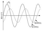
图4是驱动和敏感模态的振动信号示意图。Figure 4 is a schematic diagram of the vibration signals of the driving and sensing modes.
图5是控制电路原理图。Figure 5 is a schematic diagram of the control circuit.
图6是霍尔传感器的工作原理图。Fig. 6 is the working principle diagram of the Hall sensor.
图中各标号表示:The symbols in the figure represent:
1、悬浮质量块;2、检测传感器;21、x向传感器;22、y向传感器;3、绕组线圈;31、x向线圈;32、y向线圈;4、固定永磁铁;5、基座。1. Suspended mass; 2. Detection sensor; 21, x-direction sensor; 22, y-direction sensor; 3. winding coil; 31, x-direction coil; 32, y-direction coil; 4. fixed permanent magnet; 5. base .
具体实施方式Detailed ways
以下将结合说明书附图和具体实施例对本发明做进一步详细说明。The present invention will be further described in detail below with reference to the accompanying drawings and specific embodiments.
如图1所示,本发明的一种基于上推式磁悬浮平台的集中质量振动陀螺,包括悬浮质量块1、检测传感器2、基座5及多个绕组线圈3和固定永磁铁4,检测传感器2、绕组线圈3、固定永磁铁4均安装于基座5上,悬浮质量块1在绕组线圈3和固定永磁铁4的作用下悬浮于检测传感器2上方;多个绕组线圈3以检测传感器2为圆心均匀分布于基座5上,多个固定永磁铁4以检测传感器2为圆心均匀分布于基座5上,检测传感器2与绕组线圈3通过控制电路连接,检测传感器2用于检测悬浮质量块1的位置和磁场变化。As shown in Figure 1, a concentrated mass vibrating gyroscope based on a push-up magnetic suspension platform of the present invention includes a suspended
其中固定永磁体4和绕组线圈3用于实现悬浮质量块1的稳定悬浮,绕组线圈3同时还负责驱动悬浮质量块1的稳定振动,利用绕组线圈3对悬浮质量块1进行驱动,保证悬浮质量块1能够在一定范围内做稳定振动,为实现角速度的测量做准备。The fixed
绕组线圈3分别沿检测传感器2对称设置。The winding coils 3 are respectively arranged symmetrically along the
绕组线圈3的数量至少为三个。本实施例中,绕组线圈3为四个,检测传感器2包括两互相垂直设置的x向传感器21和y向传感器22,绕组线圈3包括x向线圈31和y向线圈32,x向线圈31沿x向传感器21对称设置,y向线圈32沿y向传感器22对称设置。两个x向线圈31和两个y向线圈32。The number of winding
检测传感器2为电容检测传感器或光电检测传感器或霍尔传感器。本实施例中采用的是霍尔传感器。The
绕组线圈3与检测传感器2之间的距离为P1,固定永磁铁4和检测传感器2之间的距离为P2,其中P2>P1。固定永磁铁4位于绕组线圈3外侧。The distance between the winding
控制电路位于基座5上,控制电路包括第一模数转换器,数字信号处理器,第二模数转换器,第一模数转换器接收检测传感器2检测出悬浮质量块1的位置信号并将其转换为数字信号输入数字信号处理器中,由数字信号处理器计算悬浮质量块1的实际位移值及偏移量,进而输出绕组线圈3的电流信号,再由第二模数转换器将该信号转换为模拟信号输入至绕组线圈3中。The control circuit is located on the
悬浮质量块1的驱动信号与稳定悬浮信号都与绕组线圈3通入的电流有关,且为了实现稳定的控制,驱动和悬浮均有相应的检测装置(即检测传感器2)以实现闭环控制。Both the driving signal and the stable suspension signal of the
本实施例的控制电路,能够实现谐振子的稳定悬浮,通过电磁检测传感器2测试悬浮质量块1(谐振子)的位置作为反馈,从而达到一定精度的稳定悬浮。采用其他常规现有的控制电路也能实现本发明。The control circuit of this embodiment can realize the stable suspension of the resonator, and use the
本实施例中,绕组线圈3、固定永磁铁4均匀地成圆形布置在基座5上,检测传感器2则分别沿着坐标轴x轴、y轴的方向安装。悬浮振动块1则位于绕组线圈3及固定永磁铁4所形成圆形的中心的上方,且悬浮质量块1为磁性材料。In this embodiment, the winding
磁悬浮振动陀螺采用的驱动方式是电磁悬浮与驱动,霍尔传感器用于闭环驱动和检测悬浮质量块1的振动。悬浮质量块1在基座5固定永磁体4和绕组线圈3的作用下稳定悬浮,在控制电路中驱动振动程序控制下沿着x轴进行振动,并且其沿着x轴和y轴的位移信号通过其正下方的霍尔传感器检测输出,驱动振动程序控制绕组线圈3中的电流,从而实现稳定悬浮与振动。The driving method of the magnetic levitation vibrating gyroscope is electromagnetic levitation and driving, and the Hall sensor is used for closed-loop driving and detecting the vibration of the suspended
为实现磁悬浮振动陀螺的工作,首先需要将振动悬浮质量块1悬浮起来,图2为悬浮质量块1稳定闭环控制示意图,其悬浮基本原理是磁悬浮原理,外部检测传感器2可以按照布置方式有选择性地测量定向的磁场变化,反映悬浮质量块1在某一固定方向的位移量,其检测的位移量是悬浮质量块1的实际位移量,与目标位移比较后可以判断出悬浮质量块1相对偏移量,然后数字信号处理器(本实施例为单片机)会发出信号改变通过绕组线圈3的电流,从而改变一个轴向上两个绕组线圈3给悬浮质量块1的合力,使悬浮质量块1向着偏移量减少的方向移动,所以悬浮质量块1的稳定是相对的,是基于绕组线圈3变化磁场的控制使其位移控制在一定范围内。In order to realize the work of the magnetic levitation vibrating gyroscope, the vibrating suspension
将悬浮质量块1(即谐振子)稳定悬浮后,即可对谐振子的振动进行驱动,以便于实现角速度测量。如图3所示,本发明中,谐振子的振动由绕组线圈3直接驱动,通过控制通入绕组线圈3的电流即可实现谐振子的振动控制。同时,由于绕组线圈3还负责谐振子的悬浮,所以通入的电流信号应是实现悬浮和驱动控制的叠加。在本实施例中,将绕组线圈3中通入电流,使得谐振子在电磁力


其中,


当谐振子处于稳定振动状态时,即可对输入的角速度进行检测。当磁悬浮平台绕着Z轴旋转时或有角速度


其中,为X轴品质因数,


利用检测传感器测出Y向的振动信号,经过解调即可得到对应的角速度大小。由上述分析可知,由于谐振子质量、结构刚度、阻尼等参数都是已知的常数,所以Y方向上的振动幅值


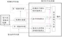
获得振动信号后,还需要将这一信号进行解调,所以还需配备控制电路。本实施例的控制电路图为常规的陀螺控制电路图。如图5所示为控制电路原理图,它主要包括数字信号处理器、检测闭环回路、驱动闭环回路这三个模块。After the vibration signal is obtained, the signal needs to be demodulated, so a control circuit is also required. The control circuit diagram of this embodiment is a conventional gyro control circuit diagram. Figure 5 shows the schematic diagram of the control circuit, which mainly includes three modules: digital signal processor, detection closed-loop loop, and driving closed-loop loop.
数字信号处理器需要依据检测再平衡控制回路算法、悬浮控制算法、驱动自动增益控制回路算法所输出的数据进行分析,进而实现陀螺误差抑制与补偿,提高陀螺的性能。The digital signal processor needs to analyze the data output by the detection rebalance control loop algorithm, the suspension control algorithm, and the driving automatic gain control loop algorithm, so as to realize the gyro error suppression and compensation, and improve the performance of the gyro.
检测闭环回路主要包括第一模数转换器AD转换和检测再平衡控制回路算法模块。陀螺的敏感振动信号由霍尔传感器进行测量,所获得的信号为模拟信号,将其转换为数字信号后输入检测再平衡控制回路算法中。通过解调检测模态振动信号,即可得到输入角速度的大小,并且这一信号会与驱动自动增益控制回路算法和悬浮控制算法的输出结果进行综合,实现谐振子的稳定悬浮和驱动。The detection closed loop mainly includes the first analog-to-digital converter AD conversion and the detection rebalance control loop algorithm module. The sensitive vibration signal of the gyroscope is measured by the Hall sensor, and the obtained signal is an analog signal, which is converted into a digital signal and then input into the detection and rebalance control loop algorithm. By demodulating and detecting the modal vibration signal, the magnitude of the input angular velocity can be obtained, and this signal will be integrated with the output results of the driving automatic gain control loop algorithm and the suspension control algorithm to realize the stable suspension and driving of the harmonic oscillator.
驱动闭环回路主要包括驱动自动增益控制回路算法和第二模数转换器DA转换,它主要实现谐振子驱动模态的稳定激励,驱动信号由数字处理器综合分析后给出,然后将数字信号转换为模拟信号,即可实现对谐振子的驱动。The driving closed-loop loop mainly includes the driving automatic gain control loop algorithm and the second analog-to-digital converter DA conversion, which mainly realizes the stable excitation of the resonator driving mode. The driving signal is given after comprehensive analysis by the digital processor, and then the digital signal is converted. As an analog signal, the driving of the harmonic oscillator can be realized.
具体步骤如下:首先依据悬浮控制算法和驱动自动增益控制回路算法得出需要施加在绕组线圈3上的电流,并利用第二模数转换器将该计算结果由数字信号转换为模拟信号,从而实现振动悬浮质量块1的稳定悬浮和振动控制。当沿着Z轴有角速度输入时,振动悬浮质量块1会在Y向产生振动,该振动信号会被相应的霍尔传感器检测到。利用第一模数转换器进行AD转换,将检测到的模拟信号转换为数字信号,该数字信号作为反馈信息同时输入至驱动自动增益控制回路算法、悬浮控制算法和检测再平衡控制回路算法。经过这三种算法的分析,结合陀螺误差抑制与补偿算法,即可输出较高精度的角速度测试数据,从而实现角速度的测量。同时,这些算法所产生的数据会作为继续维持悬浮以及驱动振动的反馈信息,从而实现更加稳定的悬浮及驱动控制。The specific steps are as follows: first, according to the suspension control algorithm and the driving automatic gain control loop algorithm, the current that needs to be applied to the winding
本实施例中的悬浮控制算法,驱动自动增益控制回路算法和检测再平衡控制回路算法均为常规算法。The suspension control algorithm, the driving automatic gain control loop algorithm and the detection rebalancing control loop algorithm in this embodiment are all conventional algorithms.
由于悬浮质量块1与基座5分离,所以只能够采用非接触测量的方式对陀螺所需的位移信号进行测量。非接触检测方式多种多样,本发明所采用的检测方式为霍尔传感器检测。Since the suspended
霍尔传感器一般由半导体材料制作而成,其工作原理如图6所示,一个通有电流的半导体薄片如果被放在均匀的磁场中,按图中所示电流沿着X方向,电场强度为
基于霍尔效应的霍尔传感器由于具有体积小、重量轻、抗震动、耐冲击和寿命长等优点,广泛应用于检测带磁性物体位移。本发明将两个分别负责驱动轴和检测轴信号测量的霍尔传感器分布在一起,但正由于其方向的敏感性,两个霍尔传感器能够分别检测悬浮永磁体在X轴和Y轴方向上的位移量,互相不会产生干扰。Hall sensors based on the Hall effect are widely used to detect the displacement of magnetic objects due to their advantages of small size, light weight, anti-vibration, shock resistance and long life. The present invention distributes two Hall sensors responsible for signal measurement of the drive shaft and the detection shaft respectively, but due to the sensitivity of their directions, the two Hall sensors can detect the suspension permanent magnets in the X-axis and Y-axis directions respectively. The displacements will not interfere with each other.
虽然本发明已以较佳实施例揭露如上,然而并非用以限定本发明。任何熟悉本领域的技术人员,在不脱离本发明技术方案范围的情况下,都可利用上述揭示的技术内容对本发明技术方案做出许多可能的变动和修饰,或修改为等同变化的等效实施例。因此,凡是未脱离本发明技术方案的内容,依据本发明技术实质对以上实施例所做的任何简单修改、等同变化及修饰,均应落在本发明技术方案保护的范围内。Although the present invention has been disclosed above with preferred embodiments, it is not intended to limit the present invention. Any person skilled in the art, without departing from the scope of the technical solution of the present invention, can make many possible changes and modifications to the technical solution of the present invention by using the technical content disclosed above, or modify it into an equivalent implementation of equivalent changes. example. Therefore, any simple modifications, equivalent changes and modifications made to the above embodiments according to the technical essence of the present invention without departing from the content of the technical solutions of the present invention should fall within the protection scope of the technical solutions of the present invention.
Claims (8)


Priority Applications (1)
| Application Number | Priority Date | Filing Date | Title |
|---|---|---|---|
| CN201911237608.5ACN110672082B (en) | 2019-12-06 | 2019-12-06 | Concentrated mass vibrating gyroscope based on push-up magnetic suspension platform |
Applications Claiming Priority (1)
| Application Number | Priority Date | Filing Date | Title |
|---|---|---|---|
| CN201911237608.5ACN110672082B (en) | 2019-12-06 | 2019-12-06 | Concentrated mass vibrating gyroscope based on push-up magnetic suspension platform |
Publications (2)
| Publication Number | Publication Date |
|---|---|
| CN110672082A CN110672082A (en) | 2020-01-10 |
| CN110672082Btrue CN110672082B (en) | 2020-02-28 |
Family
ID=69088357
Family Applications (1)
| Application Number | Title | Priority Date | Filing Date |
|---|---|---|---|
| CN201911237608.5AActiveCN110672082B (en) | 2019-12-06 | 2019-12-06 | Concentrated mass vibrating gyroscope based on push-up magnetic suspension platform |
Country Status (1)
| Country | Link |
|---|---|
| CN (1) | CN110672082B (en) |
Families Citing this family (3)
| Publication number | Priority date | Publication date | Assignee | Title |
|---|---|---|---|---|
| CN112987579B (en)* | 2021-05-13 | 2021-07-30 | 中国人民解放军国防科技大学 | Method, system and device for measuring suspension stiffness in electromagnetic suspension control system |
| CN114977891A (en)* | 2022-06-24 | 2022-08-30 | 长城汽车股份有限公司 | Magnetic levitation device, suspension control method of magnetic levitation device, vehicle and storage medium |
| CN120352137B (en)* | 2025-06-20 | 2025-08-29 | 冈田智能(江苏)股份有限公司 | A spindle simulation vibration loading test device and its working method |
Family Cites Families (6)
| Publication number | Priority date | Publication date | Assignee | Title |
|---|---|---|---|---|
| CN100483074C (en)* | 2006-01-19 | 2009-04-29 | 上海交通大学 | Electromagnetic levitation static driven micro-rotation gyro |
| CN100458366C (en)* | 2006-06-08 | 2009-02-04 | 上海交通大学 | Active suspension permanent magnet ring rotor acynchronous induction micro machinery gyroscope gyroscope |
| CN100504297C (en)* | 2007-03-08 | 2009-06-24 | 上海交通大学 | Internally stable electromagnetic levitation ring rotor micro-rotating gyroscope |
| CN201440073U (en)* | 2009-05-07 | 2010-04-21 | 洪证南 | Rotary magnetic suspension device |
| US20140290365A1 (en)* | 2013-04-02 | 2014-10-02 | Tao Ju | Mems device |
| CN102901556B (en)* | 2012-10-09 | 2014-04-16 | 北京航空航天大学 | Magnetic suspension type ultra-low-frequency vibration sensor |
- 2019
- 2019-12-06CNCN201911237608.5Apatent/CN110672082B/enactiveActive
Also Published As
| Publication number | Publication date |
|---|---|
| CN110672082A (en) | 2020-01-10 |
Similar Documents
| Publication | Publication Date | Title |
|---|---|---|
| CN110672082B (en) | Concentrated mass vibrating gyroscope based on push-up magnetic suspension platform | |
| JP3214304U (en) | Equilibrium MEMS type inertial angle sensor | |
| CN115876182B (en) | Electrode error modeling method of hemispherical resonator gyroscope | |
| US6598455B1 (en) | Non-inertial calibration of vibratory gyroscopes | |
| CN105136170B (en) | A kind of suspension rotor class gyroscopic drift error high accuracy online compensation method | |
| CN112284368A (en) | A fully differential high-precision X-axis silicon micro-gyroscope | |
| EP3249355B1 (en) | Systems and methods for bias suppression in a non-degenerate mems sensor | |
| CN111780737B (en) | High-precision horizontal axis silicon micro gyroscope based on tuning fork driving effect | |
| CN106932609A (en) | A kind of axle inertial sensors of four mass MEMS of single anchor point six | |
| CN106918720B (en) | A kind of filament restricted type acceleration transducer | |
| CN105716595B (en) | A kind of rotor deflection modulation error compensation method of suspension class gyroscope | |
| CN108710001B (en) | Two-axis integrated gyroscope accelerometer and servo control method | |
| CN115979311A (en) | PIGA (particle image guided Algorithm) cross quadratic term coefficient calibration method, system, equipment and medium | |
| CN1188681C (en) | Optical method of dynamic balance test for gyro rotor | |
| RU2329467C1 (en) | Inertial platform | |
| Maruyama et al. | An application of active magnetic bearing to gyroscopic and inertial sensors | |
| Xia et al. | Monolithic fully decoupled tri-axis gyroscope with lateral-comb and low cross-coupling | |
| Bogolyubov et al. | Astatic gyrocompass based on a hybrid micromechanical gyroscope | |
| Cui et al. | A tactical-grade monolithic horizontal dual-axis MEMS gyroscope based on off-plane quadrature coupling suppression silicon gratings | |
| US5886260A (en) | Centripetal opposed pendulous accelerometer | |
| CN109556590B (en) | Resonance ring/multi-resonance ring six-axis inertial sensor | |
| GB2149504A (en) | Apparatus for measuring inertial specific force and angular rate of a moving body and accelerometer assemblies particularly useful therein | |
| RU2296300C1 (en) | Integrating micro-mechanical vibration gyroscope | |
| Hu et al. | Analysis of mass unbalance torque on a spinning superconducting rotor | |
| CN114608609B (en) | A method for compensating axial magnetic flux uniformity error of Lorentz force magnetic bearing |
Legal Events
| Date | Code | Title | Description |
|---|---|---|---|
| PB01 | Publication | ||
| PB01 | Publication | ||
| SE01 | Entry into force of request for substantive examination | ||
| SE01 | Entry into force of request for substantive examination | ||
| GR01 | Patent grant | ||
| GR01 | Patent grant |