CN110671960B - Chemical heat exchanger - Google Patents
Chemical heat exchangerDownload PDFInfo
- Publication number
- CN110671960B CN110671960BCN201911040033.8ACN201911040033ACN110671960BCN 110671960 BCN110671960 BCN 110671960BCN 201911040033 ACN201911040033 ACN 201911040033ACN 110671960 BCN110671960 BCN 110671960B
- Authority
- CN
- China
- Prior art keywords
- heat exchange
- conveying pipe
- fixed
- pipe
- end plate
- Prior art date
- Legal status (The legal status is an assumption and is not a legal conclusion. Google has not performed a legal analysis and makes no representation as to the accuracy of the status listed.)
- Active
Links
Images

Classifications
- F—MECHANICAL ENGINEERING; LIGHTING; HEATING; WEAPONS; BLASTING
- F28—HEAT EXCHANGE IN GENERAL
- F28D—HEAT-EXCHANGE APPARATUS, NOT PROVIDED FOR IN ANOTHER SUBCLASS, IN WHICH THE HEAT-EXCHANGE MEDIA DO NOT COME INTO DIRECT CONTACT
- F28D21/00—Heat-exchange apparatus not covered by any of the groups F28D1/00 - F28D20/00
Landscapes
- Engineering & Computer Science (AREA)
- Physics & Mathematics (AREA)
- Thermal Sciences (AREA)
- Mechanical Engineering (AREA)
- General Engineering & Computer Science (AREA)
- Heat-Exchange Devices With Radiators And Conduit Assemblies (AREA)
Abstract
Description
Translated fromChinese技术领域technical field
本发明涉及化工设备技术领域,更具体的说涉及一种化工换热器。The invention relates to the technical field of chemical equipment, in particular to a chemical heat exchanger.
背景技术Background technique
现有化工中用的换热器中,其一般是换热进料管的外侧壁上固定散热翅片或散热板,进行散热,而换热进料管为了保证内部流动的物料能够换热彻底,其需要将换热进料管进行折弯盘绕,以增加换热效果,其使得换热进料管总长度增加,大大增加换热器的体积。In the heat exchangers used in the existing chemical industry, generally, heat dissipation fins or heat dissipation plates are fixed on the outer side wall of the heat exchange feed pipe to dissipate heat. , it needs to bend and coil the heat exchange feed pipe to increase the heat exchange effect, which increases the total length of the heat exchange feed pipe and greatly increases the volume of the heat exchanger.
发明内容SUMMARY OF THE INVENTION
本发明的目的就是针对现有技术之不足,而提供一种化工换热器,它在中部输送管的内部设置螺旋轴,使得换热原料可以在中部输送管中增加流动时间,增加换热效果和效率,无需增长中部输水管的长度,大大缩小换热器的体积,降低制造成本。The purpose of the present invention is to aim at the deficiencies of the prior art, and provide a chemical heat exchanger, which is provided with a screw shaft inside the middle conveying pipe, so that the heat exchange raw materials can increase the flow time in the middle conveying pipe and increase the heat exchange effect. And efficiency, no need to increase the length of the middle water pipe, greatly reduce the volume of the heat exchanger and reduce the manufacturing cost.
本发明的技术解决措施如下:The technical solutions of the present invention are as follows:
一种化工换热器,包括主壳体,所述主壳体的中部固定有多个换热板,换热板的外侧壁固定在主壳体的内侧壁上,换热板上成型有多个换热通孔,中部输送管插套在所有的换热板的中部通孔中,中部输送管的外侧壁焊接固定在中部通孔的内侧壁上;A chemical heat exchanger includes a main shell, a plurality of heat exchange plates are fixed in the middle of the main shell, the outer side wall of the heat exchange plate is fixed on the inner side wall of the main shell, and the heat exchange plate is formed with a plurality of heat exchange plates. a heat exchange through hole, the middle conveying pipe is inserted and sleeved in the middle through hole of all the heat exchange plates, and the outer side wall of the middle conveying pipe is welded and fixed on the inner side wall of the middle through hole;
所述中部输送管的顶端伸出主壳体的顶部固定有的顶部盖板,中部输送管的底端伸出主壳体的底部固定有的下底板;The top end of the middle conveying pipe extends out of the top cover plate fixed at the top of the main casing, and the bottom end of the middle conveying pipe extends out of the lower bottom plate fixed at the bottom of the main casing;
所述中部输送管中安装有螺旋轴,螺旋轴的螺旋翅片的边部靠近中部输送管的内侧壁。A screw shaft is installed in the middle conveying pipe, and the edge of the helical fins of the screw shaft is close to the inner side wall of the middle conveying pipe.
上下相邻的两个换热板的换热通孔上下错开。The heat exchange through holes of the two adjacent heat exchange plates up and down are staggered up and down.
所述螺旋轴插套在中部输送管中,中部输送管的上端和底端外侧壁均成型有径向连接边,中部输送管的上端和底端内侧壁均成型有径向限位槽,螺旋轴的底端成型有连接端板,连接端板嵌套在中部输送管的底端的径向限位槽中,连接端板的顶面压靠在下端的径向限位槽的顶面并通过螺栓固定连接在中部输送管上,连接端板上成型有多个出料通孔。The screw shaft is inserted and sleeved in the middle conveying pipe, the upper end and the outer side wall of the bottom end of the middle conveying pipe are formed with radial connecting edges, and the upper end and the inner side wall of the bottom end of the middle conveying pipe are both formed with radial limit grooves, and the spiral The bottom end of the shaft is formed with a connecting end plate, the connecting end plate is nested in the radial limiting groove at the bottom end of the middle conveying pipe, and the top surface of the connecting end plate is pressed against the top surface of the radial limiting groove at the lower end and passes through The bolt is fixedly connected to the middle conveying pipe, and the connecting end plate is formed with a plurality of discharge through holes.
所述中部输送管的顶端的径向限位槽中嵌套有上连接端板,上连接端板通过螺栓固定连接在中部输送管上,上连接端板的底面中部成型有螺接柱,螺接柱螺接在螺旋轴的顶端具有的螺接孔中,上连接端板上成型有多个上进料通孔。The upper connecting end plate is nested in the radial limiting groove at the top of the middle conveying pipe, the upper connecting end plate is fixedly connected to the middle conveying pipe by bolts, and the middle part of the bottom surface of the upper connecting end plate is formed with a threaded connection column, and the bolt The connecting post is screwed into the screwing hole provided at the top end of the screw shaft, and a plurality of upper feeding through holes are formed on the upper connecting end plate.
所述主壳体的侧板的内部成型有内腔体,内腔体中填充有隔热材料。An inner cavity is formed inside the side plate of the main casing, and the inner cavity is filled with heat insulating material.
所述顶部盖板的左部通接有进气管体,顶部盖板的右部通接有出气管体。The left part of the top cover plate is connected with the air inlet pipe body, and the right part of the top cover plate is connected with the air outlet pipe body.
所述中部输送管的上部插套在顶部盖板的上中部通孔,中部输送管的上部外侧壁固定在上中部通孔的内侧壁上,中部输送管的下部插套在下底板的下中部通孔中,中部输送管的下部外侧壁焊接固定在下中部通孔的内侧壁上。The upper part of the middle conveying pipe is inserted into the upper middle through hole of the top cover plate; In the hole, the lower outer side wall of the middle conveying pipe is welded and fixed on the inner side wall of the lower middle through hole.
本发明的有益效果在于:The beneficial effects of the present invention are:
它在中部输送管的内部设置螺旋轴,使得换热原料可以在中部输送管中增加流动时间,增加换热效果和效率,无需增长中部输水管的长度,大大缩小换热器的体积,降低制造成本。It sets a screw shaft inside the middle conveying pipe, so that the heat exchange raw material can increase the flow time in the middle conveying pipe, increase the heat exchange effect and efficiency, without increasing the length of the middle water conveying pipe, greatly reducing the volume of the heat exchanger and reducing the manufacturing cost.
附图说明Description of drawings
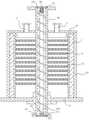
图1为本发明的局部结构示意图;Fig. 1 is the partial structure schematic diagram of the present invention;
图2为本发明的局部放大图。FIG. 2 is a partial enlarged view of the present invention.
具体实施方式Detailed ways
实施例:见图1至图2所示,一种化工换热器,包括主壳体10,所述主壳体10的中部固定有多个换热板11,换热板11的外侧壁固定在主壳体10的内侧壁上,换热板11上成型有多个换热通孔111,中部输送管20插套在所有的换热板11的中部通孔中,中部输送管20的外侧壁焊接固定在中部通孔的内侧壁上;Example: As shown in Figures 1 to 2, a chemical heat exchanger includes a
所述中部输送管20的顶端伸出主壳体10的顶部固定有的顶部盖板12,中部输送管20的底端伸出主壳体10的底部固定有的下底板13;The top end of the
所述中部输送管20中安装有螺旋轴210,螺旋轴210的螺旋翅片的边部靠近中部输送管20的内侧壁。A
进一步的说,上下相邻的两个换热板11的换热通孔111上下错开。Further, the heat exchange through
进一步的说,所述螺旋轴210插套在中部输送管20中,中部输送管20的上端和底端外侧壁均成型有径向连接边21,中部输送管20的上端和底端内侧壁均成型有径向限位槽22,螺旋轴210的底端成型有连接端板211,连接端板211嵌套在中部输送管20的底端的径向限位槽22中,连接端板211的顶面压靠在下端的径向限位槽22的顶面并通过螺栓固定连接在中部输送管20上,连接端板211上成型有多个出料通孔212。Further, the
进一步的说,所述中部输送管20的顶端的径向限位槽22中嵌套有上连接端板23,上连接端板23通过螺栓固定连接在中部输送管20上,上连接端板23的底面中部成型有螺接柱24,螺接柱24螺接在螺旋轴210的顶端具有的螺接孔中,上连接端板23上成型有多个上进料通孔231。Further, an upper connecting
进一步的说,所述主壳体10的侧板的内部成型有内腔体,内腔体中填充有隔热材料1。Further, an inner cavity is formed inside the side plate of the
进一步的说,所述顶部盖板12的左部通接有进气管体2,顶部盖板12的右部通接有出气管体3。Further, the left part of the
进一步的说,所述中部输送管20的上部插套在顶部盖板12的上中部通孔,中部输送管20的上部外侧壁固定在上中部通孔的内侧壁上,中部输送管20的下部插套在下底板13的下中部通孔中,中部输送管20的下部外侧壁焊接固定在下中部通孔的内侧壁上。Further, the upper part of the
工作原理:使用时,将中部输送管20的顶端的径向连接边21与输送管进行连通,中部输送管20的底端的径向连接边21与出料管进行连通,而其中一个进气管体2与送气管连通,出气管体3与回气管连通,使用时,高热量的物料从上进料通孔231进入并沿着螺旋轴210的螺旋槽进行输送,最后从出料通孔212排出,而气体由进气管体2进入主壳体10中并从出气管体3排出,在主壳体中,高热量的物料的热量通过换热板11与主壳体10中的气体进行快速彻底换热,使得高热量的物料实现快速降温,同时,气体的温度提高,使得气体可以输送给其他工序中进行热量提供。Working principle: When in use, the radial connecting
Claims (5)
Priority Applications (1)
| Application Number | Priority Date | Filing Date | Title |
|---|---|---|---|
| CN201911040033.8ACN110671960B (en) | 2019-10-29 | 2019-10-29 | Chemical heat exchanger |
Applications Claiming Priority (1)
| Application Number | Priority Date | Filing Date | Title |
|---|---|---|---|
| CN201911040033.8ACN110671960B (en) | 2019-10-29 | 2019-10-29 | Chemical heat exchanger |
Publications (2)
| Publication Number | Publication Date |
|---|---|
| CN110671960A CN110671960A (en) | 2020-01-10 |
| CN110671960Btrue CN110671960B (en) | 2020-10-13 |
Family
ID=69085125
Family Applications (1)
| Application Number | Title | Priority Date | Filing Date |
|---|---|---|---|
| CN201911040033.8AActiveCN110671960B (en) | 2019-10-29 | 2019-10-29 | Chemical heat exchanger |
Country Status (1)
| Country | Link |
|---|---|
| CN (1) | CN110671960B (en) |
Families Citing this family (2)
| Publication number | Priority date | Publication date | Assignee | Title |
|---|---|---|---|---|
| CN112503993A (en)* | 2020-11-27 | 2021-03-16 | 岳绍斌 | Energy-saving and environment-friendly heat exchanger for production and manufacturing of chemical products |
| CN118009603B (en)* | 2024-04-09 | 2024-06-28 | 三立福新材料(福建)有限公司 | A heat exchanger for cooling chemical materials |
Citations (7)
| Publication number | Priority date | Publication date | Assignee | Title |
|---|---|---|---|---|
| JPS5637489A (en)* | 1979-09-05 | 1981-04-11 | Hitachi Ltd | Heat exchanger |
| CN1266976A (en)* | 1999-03-10 | 2000-09-20 | 特种设备公司 | High-efficiency refrigerating system |
| CN2404087Y (en)* | 2000-01-26 | 2000-11-01 | 淮阴辉煌太阳能有限公司 | Assembled spiral sleeve heat exchanger |
| CN2781315Y (en)* | 2005-03-29 | 2006-05-17 | 江苏曙光压力容器有限公司 | high-efficiency heat exchange tube |
| CN201335638Y (en)* | 2008-12-15 | 2009-10-28 | 王德元 | Reinforced heat-transferring smoke tube |
| CN105509516A (en)* | 2016-01-08 | 2016-04-20 | 湖州科达化工燃料有限公司 | Quick heat exchanger for chemical industry |
| CN109387096A (en)* | 2018-11-12 | 2019-02-26 | 东莞运宏模具有限公司 | Laminated water-cooling radiator |
- 2019
- 2019-10-29CNCN201911040033.8Apatent/CN110671960B/enactiveActive
Patent Citations (7)
| Publication number | Priority date | Publication date | Assignee | Title |
|---|---|---|---|---|
| JPS5637489A (en)* | 1979-09-05 | 1981-04-11 | Hitachi Ltd | Heat exchanger |
| CN1266976A (en)* | 1999-03-10 | 2000-09-20 | 特种设备公司 | High-efficiency refrigerating system |
| CN2404087Y (en)* | 2000-01-26 | 2000-11-01 | 淮阴辉煌太阳能有限公司 | Assembled spiral sleeve heat exchanger |
| CN2781315Y (en)* | 2005-03-29 | 2006-05-17 | 江苏曙光压力容器有限公司 | high-efficiency heat exchange tube |
| CN201335638Y (en)* | 2008-12-15 | 2009-10-28 | 王德元 | Reinforced heat-transferring smoke tube |
| CN105509516A (en)* | 2016-01-08 | 2016-04-20 | 湖州科达化工燃料有限公司 | Quick heat exchanger for chemical industry |
| CN109387096A (en)* | 2018-11-12 | 2019-02-26 | 东莞运宏模具有限公司 | Laminated water-cooling radiator |
Also Published As
| Publication number | Publication date |
|---|---|
| CN110671960A (en) | 2020-01-10 |
Similar Documents
| Publication | Publication Date | Title |
|---|---|---|
| CN110671960B (en) | Chemical heat exchanger | |
| CN201547959U (en) | Spiral single tube condensing heat exchanger | |
| CN106195606A (en) | The adjustable three-dimensional ribbed pipe oil cooler of a kind of oil temperature | |
| CN101431879A (en) | Heat pipe intensified electronic device radiator | |
| CN210004808U (en) | kinds of cylindrical radiator | |
| CN204806939U (en) | Capillary formula oil cooler that gathers | |
| CN205481706U (en) | When temperature field electric heating pipe | |
| CN211040546U (en) | Straight tube type double-helix ultraviolet L ED lamp device | |
| CN115768036A (en) | A liquid cooling system based on submerged heat exchanger | |
| CN209783344U (en) | Front-sparse rear-dense tube-fin heat exchanger | |
| CN209558990U (en) | A rapid heat dissipation corrugated heat exchange tube | |
| CN204515661U (en) | A kind of rectilinear CPU water-filled radiator | |
| CN213066680U (en) | An efficient cooling feed hopper | |
| CN202238058U (en) | Continuous nitrator for nitrochlorobenzene | |
| CN201497395U (en) | finned radiator | |
| CN207585393U (en) | energy-saving heating radiator | |
| CN207540397U (en) | Activated carbon recycling smoke temperature reducer | |
| CN111795592A (en) | A continuous sauce cooler | |
| CN109900153A (en) | A kind of heat exchanger feeding device | |
| CN205420376U (en) | Heat transfer formula cooling bio -pharmaceuticals fermentation cylinder | |
| CN219754921U (en) | A hydraulic pump station | |
| CN209026156U (en) | A planetary reducer cooling shell | |
| CN221657942U (en) | A cooling device for die casting mold | |
| CN223404905U (en) | A reactor external condensation device | |
| CN204043446U (en) | A kind of compact tubular type finned heat exchanger |
Legal Events
| Date | Code | Title | Description |
|---|---|---|---|
| PB01 | Publication | ||
| PB01 | Publication | ||
| SE01 | Entry into force of request for substantive examination | ||
| SE01 | Entry into force of request for substantive examination | ||
| TA01 | Transfer of patent application right | ||
| TA01 | Transfer of patent application right | Effective date of registration:20200914 Address after:247200 Anhui city of Chizhou Province East Economic Development Zone Applicant after:ANHUI SUQI CHEMICAL Co.,Ltd. Address before:NO.67, Fuhua Road, Nanxun Economic Development Zone, Nanxun District, Huzhou City, Zhejiang Province Applicant before:Li Jiejie | |
| GR01 | Patent grant | ||
| GR01 | Patent grant | ||
| CP03 | Change of name, title or address | ||
| CP03 | Change of name, title or address | Address after:247200 East to Economic Development Zone, Chizhou City, Anhui Province Patentee after:Anhui Xinnongda Chemical Co.,Ltd. Country or region after:China Address before:247200 East to Economic Development Zone, Chizhou City, Anhui Province Patentee before:ANHUI SUQI CHEMICAL Co.,Ltd. Country or region before:China |