CN110664480A - Jet stripping electric cutting head and jet stripping electric cutting device - Google Patents
Jet stripping electric cutting head and jet stripping electric cutting deviceDownload PDFInfo
- Publication number
- CN110664480A CN110664480ACN201910945247.3ACN201910945247ACN110664480ACN 110664480 ACN110664480 ACN 110664480ACN 201910945247 ACN201910945247 ACN 201910945247ACN 110664480 ACN110664480 ACN 110664480A
- Authority
- CN
- China
- Prior art keywords
- gas
- metal
- air
- flow channel
- pipe body
- Prior art date
- Legal status (The legal status is an assumption and is not a legal conclusion. Google has not performed a legal analysis and makes no representation as to the accuracy of the status listed.)
- Pending
Links
- 238000005520cutting processMethods0.000titleclaimsabstractdescription45
- 239000002184metalSubstances0.000claimsabstractdescription158
- 230000007704transitionEffects0.000claimsdescription52
- 230000005540biological transmissionEffects0.000claimsdescription29
- 238000005452bendingMethods0.000claimsdescription16
- 238000000576coating methodMethods0.000claimsdescription7
- 238000005345coagulationMethods0.000claimsdescription4
- 230000015271coagulationEffects0.000claimsdescription4
- 238000002347injectionMethods0.000claimsdescription4
- 239000007924injectionSubstances0.000claimsdescription4
- 210000000056organAnatomy0.000abstractdescription27
- 210000000683abdominal cavityAnatomy0.000abstractdescription19
- 230000007423decreaseEffects0.000abstractdescription10
- 238000000926separation methodMethods0.000abstractdescription9
- 238000010586diagramMethods0.000description10
- 238000002224dissectionMethods0.000description7
- 238000002357laparoscopic surgeryMethods0.000description7
- 238000000034methodMethods0.000description7
- 239000000243solutionSubstances0.000description7
- 239000011248coating agentSubstances0.000description5
- 210000003437tracheaAnatomy0.000description5
- 230000003187abdominal effectEffects0.000description4
- 230000006872improvementEffects0.000description3
- 238000001356surgical procedureMethods0.000description3
- CURLTUGMZLYLDI-UHFFFAOYSA-NCarbon dioxideChemical compoundO=C=OCURLTUGMZLYLDI-UHFFFAOYSA-N0.000description2
- 208000005646PneumoperitoneumDiseases0.000description2
- 238000007664blowingMethods0.000description2
- 230000003749cleanlinessEffects0.000description2
- 238000005260corrosionMethods0.000description2
- 238000010292electrical insulationMethods0.000description2
- 230000005611electricityEffects0.000description2
- 238000004134energy conservationMethods0.000description2
- 206010069808Electrical burnDiseases0.000description1
- 206010014405ElectrocutionDiseases0.000description1
- 210000003484anatomyAnatomy0.000description1
- 230000000740bleeding effectEffects0.000description1
- 210000004204blood vesselAnatomy0.000description1
- 229910002092carbon dioxideInorganic materials0.000description1
- 239000001569carbon dioxideSubstances0.000description1
- 238000004140cleaningMethods0.000description1
- 238000004891communicationMethods0.000description1
- 238000010276constructionMethods0.000description1
- 230000007797corrosionEffects0.000description1
- 201000010099diseaseDiseases0.000description1
- 208000037265diseases, disorders, signs and symptomsDiseases0.000description1
- 238000009297electrocoagulationMethods0.000description1
- 239000012943hotmeltSubstances0.000description1
- 230000002757inflammatory effectEffects0.000description1
- 238000009434installationMethods0.000description1
- 238000004519manufacturing processMethods0.000description1
- 239000000463materialSubstances0.000description1
- 238000012986modificationMethods0.000description1
- 230000004048modificationEffects0.000description1
- 210000005036nerveAnatomy0.000description1
- 238000002360preparation methodMethods0.000description1
- 230000008569processEffects0.000description1
- 239000007921spraySubstances0.000description1
- 230000001954sterilising effectEffects0.000description1
- 238000004659sterilization and disinfectionMethods0.000description1
- 238000003466weldingMethods0.000description1
Images


Classifications
- A—HUMAN NECESSITIES
- A61—MEDICAL OR VETERINARY SCIENCE; HYGIENE
- A61B—DIAGNOSIS; SURGERY; IDENTIFICATION
- A61B18/00—Surgical instruments, devices or methods for transferring non-mechanical forms of energy to or from the body
- A61B18/04—Surgical instruments, devices or methods for transferring non-mechanical forms of energy to or from the body by heating
- A61B18/12—Surgical instruments, devices or methods for transferring non-mechanical forms of energy to or from the body by heating by passing a current through the tissue to be heated, e.g. high-frequency current
- A—HUMAN NECESSITIES
- A61—MEDICAL OR VETERINARY SCIENCE; HYGIENE
- A61B—DIAGNOSIS; SURGERY; IDENTIFICATION
- A61B17/00—Surgical instruments, devices or methods
- A61B17/02—Surgical instruments, devices or methods for holding wounds open, e.g. retractors; Tractors
- A61B17/0218—Surgical instruments, devices or methods for holding wounds open, e.g. retractors; Tractors for minimally invasive surgery
- A—HUMAN NECESSITIES
- A61—MEDICAL OR VETERINARY SCIENCE; HYGIENE
- A61B—DIAGNOSIS; SURGERY; IDENTIFICATION
- A61B17/00—Surgical instruments, devices or methods
- A61B17/02—Surgical instruments, devices or methods for holding wounds open, e.g. retractors; Tractors
- A61B17/0281—Abdominal wall lifters
- A—HUMAN NECESSITIES
- A61—MEDICAL OR VETERINARY SCIENCE; HYGIENE
- A61B—DIAGNOSIS; SURGERY; IDENTIFICATION
- A61B17/00—Surgical instruments, devices or methods
- A61B17/32—Surgical cutting instruments
- A61B17/320016—Endoscopic cutting instruments, e.g. arthroscopes, resectoscopes
- A—HUMAN NECESSITIES
- A61—MEDICAL OR VETERINARY SCIENCE; HYGIENE
- A61B—DIAGNOSIS; SURGERY; IDENTIFICATION
- A61B17/00—Surgical instruments, devices or methods
- A61B17/32—Surgical cutting instruments
- A61B17/3203—Fluid jet cutting instruments
- A—HUMAN NECESSITIES
- A61—MEDICAL OR VETERINARY SCIENCE; HYGIENE
- A61B—DIAGNOSIS; SURGERY; IDENTIFICATION
- A61B17/00—Surgical instruments, devices or methods
- A61B17/32—Surgical cutting instruments
- A61B17/3203—Fluid jet cutting instruments
- A61B2017/32035—Fluid jet cutting instruments with gas or air
- A—HUMAN NECESSITIES
- A61—MEDICAL OR VETERINARY SCIENCE; HYGIENE
- A61B—DIAGNOSIS; SURGERY; IDENTIFICATION
- A61B18/00—Surgical instruments, devices or methods for transferring non-mechanical forms of energy to or from the body
- A61B2018/00982—Surgical instruments, devices or methods for transferring non-mechanical forms of energy to or from the body combined with or comprising means for visual or photographic inspections inside the body, e.g. endoscopes
Landscapes
- Health & Medical Sciences (AREA)
- Surgery (AREA)
- Life Sciences & Earth Sciences (AREA)
- Engineering & Computer Science (AREA)
- Molecular Biology (AREA)
- Public Health (AREA)
- Heart & Thoracic Surgery (AREA)
- Medical Informatics (AREA)
- Nuclear Medicine, Radiotherapy & Molecular Imaging (AREA)
- Animal Behavior & Ethology (AREA)
- General Health & Medical Sciences (AREA)
- Biomedical Technology (AREA)
- Veterinary Medicine (AREA)
- Orthopedic Medicine & Surgery (AREA)
- Physics & Mathematics (AREA)
- Plasma & Fusion (AREA)
- Otolaryngology (AREA)
- Surgical Instruments (AREA)
Abstract
Translated fromChinese
Description
Translated fromChinese技术领域technical field
本发明涉及手术器械技术领域,尤其是涉及一种喷气剥离电切头及喷气剥离电切装置。The invention relates to the technical field of surgical instruments, in particular to a jet stripping electric cutting head and a jet stripping electric cutting device.
背景技术Background technique
腹腔镜手术就是利用腹腔镜及其相关器械对腹部疾病进行的手术。为使腹腔镜手术拥有足够空间操作,需持续灌注腹腔予二氧化碳气体建立人工气腹,人工气腹是腹腔镜手术必要的条件。Laparoscopic surgery is the use of laparoscopy and related instruments for abdominal diseases. In order to have enough space for laparoscopic surgery, it is necessary to continuously perfuse the abdominal cavity with carbon dioxide gas to establish artificial pneumoperitoneum. Artificial pneumoperitoneum is a necessary condition for laparoscopic surgery.
然而,现有的设备只能将气体灌注到腹腔中,而在腹腔镜手术操作中,在对深部腹腔脏器、组织脏器的侧面或背面进行解剖时,或者有炎症的脏器与周围组织之间存在紧密粘连需要分离时,或者解剖的脏器被重要的血管和神经等组织包绕时,现有的腹腔镜常规器械在进行解剖操作时往往较为困难,而单纯的对组织电切可能会造成意外的出血,电灼伤或者造成重要脏器的副损伤。CN201811309408.1公开了一种腹腔镜手术用高频电刀,包括虽然具有电切或者喷气功能,但是结构复杂,不利于深入到腹部脏器间进行操作。However, existing devices can only infuse gas into the abdominal cavity, and in laparoscopic procedures, when dissecting deep abdominal organs, the lateral or back of tissue organs, or inflamed organs and surrounding tissue When there are tight adhesions between them that need to be separated, or when the dissected organs are surrounded by important blood vessels and nerves and other tissues, the existing laparoscopic conventional instruments are often difficult to perform dissection operations, and simple tissue electrocution may be possible. It can cause accidental bleeding, electrical burns or secondary damage to vital organs. CN201811309408.1 discloses a high-frequency electrosurgical knife for laparoscopic surgery. Although it has the function of electric cutting or air jet, the structure is complicated, which is not conducive to going deep into the abdominal organs for operation.
因此,针对上述问题本发明急需提供一种喷气剥离电切头及喷气剥离电切装置。Therefore, in view of the above problems, the present invention urgently needs to provide an air-jet stripping electric cutting head and an air-jet stripping electric cutting device.
发明内容SUMMARY OF THE INVENTION
本发明的目的在于提供一种喷气剥离电切头及喷气剥离电切装置,通过喷气剥离电切头的结构设计以解决现有技术中存在的对深部腹腔脏器、组织脏器的侧面或背面的解剖较为困难时;对有炎症的脏器与周围组织之间存在紧密粘连时,无法安全有效分离等问题。The object of the present invention is to provide a jet stripping electric cutting head and a jet stripping electric cutting device, which can solve the problem of the side or back of deep abdominal organs and tissue organs existing in the prior art through the structural design of the jet stripping electric cutting head. When the anatomy is difficult; when there is tight adhesion between the inflammatory organ and the surrounding tissue, it cannot be separated safely and effectively.
本发明提供的一种喷气剥离电切头,包括内设气体流道的金属管体,金属管体一端封闭,另一端设有与气体流道连通的进气端口,金属管体封闭处或/和紧靠金属管体封闭处的金属管体的外侧壁上开设有与气体流道连通的出气端口;气体流道的内直径由进气端口向出气端口逐渐减小或阶梯式减小。The invention provides a jet stripping electric cutting head, comprising a metal tube body with a gas flow channel inside, one end of the metal tube body is closed, and the other end is provided with an air inlet port communicating with the gas flow channel, and the closed part of the metal tube body or/ And the outer side wall of the metal pipe body close to the closed part of the metal pipe body is provided with a gas outlet port communicating with the gas flow channel; the inner diameter of the gas flow channel gradually decreases or decreases stepwise from the gas inlet port to the gas outlet port.
优选地,紧靠金属管体封闭处的金属管体的外侧壁上开设有一个与气体流道连通的出气端口。Preferably, a gas outlet port communicated with the gas flow channel is opened on the outer side wall of the metal pipe body close to the closed part of the metal pipe body.
优选地,金属管体封闭处开设有一个出气端口。Preferably, an air outlet port is opened at the closed part of the metal pipe body.
优选地,金属管体从下到上依次包括连接段,与连接段顶部连接的过渡段,与过渡段顶部连接的弯折段,过渡段和弯折段间的夹角为90°-180°;其中,连接段的纵向剖面为梯形或方形;出气端口设于弯折段上。Preferably, the metal pipe body sequentially includes a connecting section from bottom to top, a transition section connected to the top of the connecting section, and a bending section connected to the top of the transition section, and the included angle between the transition section and the bending section is 90°-180° ; Wherein, the longitudinal section of the connecting section is trapezoidal or square; the outlet port is arranged on the bending section.
优选地,进气端口的内直径为1.5mm-15mm;出气端口的内直径为0.1mm-10mm;金属管体的高度为5mm-50mm。Preferably, the inner diameter of the air inlet port is 1.5mm-15mm; the inner diameter of the air outlet port is 0.1mm-10mm; and the height of the metal pipe body is 5mm-50mm.
优选地,过渡段的侧壁上设有与气体流道连通的过渡段喷气口;过渡段喷气口与出气端口同侧设置;过渡段喷气口的内直径为0.1-10mm。Preferably, the side wall of the transition section is provided with a transition section jet port communicating with the gas flow channel; the transition section jet port is provided on the same side as the gas outlet port; the inner diameter of the transition section jet port is 0.1-10mm.
优选地,连接段和过渡段外壁均涂有绝缘涂层。Preferably, the outer walls of the connecting section and the transition section are coated with an insulating coating.
本发明还包括一种喷气剥离电切装置,包括金属输气管,金属输气管的一端安装连通有如上述中任一项所述的喷气剥离电切头,另一端安装有与金属输气管可拆卸连接的手柄;金属输气管的侧壁上设有导电柱;手柄上设有与气源连通的输气入口和与金属输气管连通的输气出口,手柄内部设有与输气入口和输气出口均连通的输气流道,手柄的输气入口与气管连通导电柱通过电线与电切电凝装置电连接。The present invention also includes a jet stripping electric cutting device, comprising a metal gas delivery pipe, one end of the metal gas delivery pipe is connected with the jet stripping electric cutting head as described in any one of the above, and the other end is mounted with a detachable connection with the metal gas delivery pipe The handle; the side wall of the metal gas pipe is provided with a conductive column; the handle is provided with a gas inlet communicated with the gas source and a gas outlet communicated with the metal gas pipe, and the handle is provided with a gas inlet and a gas outlet. All connected air delivery channels, the gas delivery inlet of the handle is in communication with the trachea and the conductive column is electrically connected with the electric cutting and coagulation device through electric wires.
优选地,输气入口的中心纵轴线与金属输气管中心纵轴线重合;Preferably, the central longitudinal axis of the gas inlet is coincident with the central longitudinal axis of the metal gas pipe;
金属输气管外壁设有绝缘层;The outer wall of the metal gas pipe is provided with an insulating layer;
导电柱与金属输气管连接处设有外套于导电柱的导电柱绝缘套;A conductive column insulating sleeve which is sheathed on the conductive column is provided at the connection between the conductive column and the metal gas pipe;
手柄外设有绝缘层;There is an insulating layer outside the handle;
手柄的材质为金属或塑料;The handle material is metal or plastic;
金属输气管一端设有外螺纹,输气出口内壁上设有内螺纹,金属输气管螺接于输气出口上;One end of the metal gas delivery pipe is provided with an external thread, the inner wall of the gas delivery outlet is provided with an inner thread, and the metal gas delivery pipe is screwed on the gas delivery outlet;
金属输气管的长度为200mm-400mm;The length of the metal gas pipe is 200mm-400mm;
输气入口、输气流道及输气出口的内直径均大于金属输气管的内直径。The inner diameter of the gas inlet, the gas channel and the gas outlet are all larger than the inner diameter of the metal gas pipe.
优选地,输气入口与导电柱分设于输气金属管两侧。Preferably, the gas transmission inlet and the conductive column are arranged on both sides of the gas transmission metal pipe.
本发明提供的一种喷气剥离电切头及喷气剥离电切装置与现有技术相比具有以下进步:Compared with the prior art, the jet stripping electric cutting head and the jet stripping electric cutting device provided by the present invention have the following improvements:
1、本发明通过金属管体一端封闭,另一端设有与气体流道连通的进气端口,金属管体封闭处或/和紧靠金属管体封闭处的金属管体的外侧壁上开设有与气体流道连通的出气端口;气体流道的内直径由进气端口向出气端口逐渐减小或阶梯式减小;本实施具体的方案为紧靠金属管体封闭处的金属管体的外侧壁上开设有一个与气体流道连通的出气端口的设计,目的提升气体的流速,让气体从气体流道通过后,出气端口喷出时,使得气体流速成倍增加,从而增加气体喷出的动能,通过金属管体结构的设计,可以将气体流道内气体的流速呈倍提升,从而喷出一定动能的气体,有助于对腹腔深部以及彼此粘连紧密组织脏器的分离,吹开腹腔内潜在间隙,方便操作者进行高效、精准和安全的解剖操作,与现有腹腔镜手术器械相比,具有解剖剥离更精准,操作性更便捷和安全性更高的优点。1. In the present invention, one end of the metal pipe body is closed, and the other end is provided with an air inlet port that communicates with the gas flow channel. The metal pipe body is closed at or/and on the outer side wall of the metal pipe body close to the metal pipe body. The gas outlet port that communicates with the gas flow channel; the inner diameter of the gas flow channel gradually decreases or decreases stepwise from the inlet port to the gas outlet port; the specific scheme of this implementation is that the outer side of the metal tube body is close to the closed part of the metal tube body The design of a gas outlet port connected to the gas flow channel on the wall is designed to increase the flow rate of the gas. Kinetic energy, through the design of the metal tube structure, the flow rate of the gas in the gas channel can be doubled, so as to eject gas with a certain kinetic energy, which is helpful for the separation of the deep abdominal cavity and the tight tissues and organs that are adhered to each other, and blowing open the abdominal cavity. The potential gap is convenient for the operator to perform efficient, precise and safe dissection operations. Compared with the existing laparoscopic surgical instruments, it has the advantages of more accurate dissection, more convenient operation and higher safety.
2、本发明通过金属管体从下到上依次包括连接段,与连接段顶部连接的过渡段,与过渡段部连接的弯折段,过渡段和弯折段间的夹角为90°-180°,本实施例优选的角度为夹角为90°;其中,连接段的纵向剖面为梯形或方形,本实施例连接段的纵向剖面为梯形;出气端口设于弯折段上;连接段和过渡段外壁均涂有绝缘涂层的设计,将金属管体划分为三段结构,可以根据实际情况任选夹角的角度,达到方便操作的目的,同时,方便绝缘涂层的设置,在保护金属管体的同时,起到绝缘电的作用,避免在电切过程中,损伤不需要治疗的脏器,提高手术的安全系数;连接段的纵向剖面为梯形,使得气体流道内的气体流速持续提高,保证气流的输送速度,有助于对腹腔深部以及彼此粘连紧密组织脏器的分离,吹开腹腔内潜在间隙,方便操作者进行高效、精准和安全的解剖操作。2. The present invention sequentially includes a connecting section from bottom to top through the metal pipe body, a transition section connected with the top of the connecting section, a bending section connected with the transition section, and the included angle between the transition section and the bending section is 90°- 180°, the preferred angle in this embodiment is 90°; wherein, the longitudinal section of the connecting section is trapezoidal or square, and the longitudinal section of the connecting section in this embodiment is trapezoidal; the air outlet is arranged on the bending section; the connecting section The design of the insulating coating and the outer wall of the transition section are designed to divide the metal pipe body into three-section structures. The angle of the included angle can be selected according to the actual situation to achieve the purpose of convenient operation. At the same time, it is convenient to set the insulating coating. While protecting the metal tube body, it also plays the role of insulating electricity, avoiding damage to organs that do not need treatment during the electric cutting process, and improving the safety factor of the operation; the longitudinal section of the connecting section is trapezoidal, which makes the gas flow rate in the gas flow channel. Continuous improvement to ensure the delivery speed of the airflow is helpful for the separation of the deep abdominal cavity and the tissues and organs that are closely adhered to each other, and to open the potential gap in the abdominal cavity, which is convenient for the operator to perform efficient, accurate and safe dissection operations.
3、本发明金属管体的结构设计是根据质量守恒和能量守恒定律,通过伯努利方程计算,得出在现有压力的气源供应下,连接段内的气体的流速逐渐呈倍提升,从而增加了气体喷出时的动能,对腹腔深部以及彼此粘连紧密组织脏器可以进行高效解剖分离。3. The structural design of the metal pipe body of the present invention is based on the laws of mass conservation and energy conservation, and is calculated by Bernoulli equation, and it is concluded that under the supply of the gas source at the existing pressure, the flow rate of the gas in the connecting section is gradually increased by 100%. Thereby, the kinetic energy of the gas is increased, and the deep abdominal cavity and the tissues and organs that are closely adhered to each other can be efficiently dissected and separated.
4、本发明通过过渡段的侧壁上设有与气体流道连通的过渡段喷气口;过渡段喷气口与出气端口同侧设置;过渡段喷气口的内直径为0.1-10mm的设计,增加了气体出口,即过渡段喷气口,可以多角度,多位置的喷射出气体,有助于对腹腔深部以及彼此粘连紧密组织脏器的分离,吹开腹腔内潜在间隙,方便操作者进行高效、精准和安全的解剖操作。4. In the present invention, a transition section jet port that communicates with the gas flow channel is provided on the side wall of the transition section; the transition section jet port is arranged on the same side as the gas outlet port; the inner diameter of the transition section jet port is 0.1-10mm. The gas outlet, that is, the transition section jet port, can spray gas from multiple angles and positions, which is helpful for the separation of deep abdominal cavity and closely adhered tissues and organs, and opens potential gaps in the abdominal cavity, which is convenient for the operator to carry out efficient, Precise and safe anatomical manipulation.
5、本发明通过金属输气管的一端安装连通有如上述中任一项所述的喷气剥离电切头,另一端安装有与金属输气管可拆卸连接的手柄;金属输气管的侧壁上设有导电柱;手柄上设有与气源连通的输气入口和与金属输气管连通的输气出口,手柄内部设有与输气入口和输气出口均连通的输气流道,手柄的输气入口与气管连通;导电柱通过电线与电切电凝装置电连接的设计,喷气剥离电切头、金属输气管和手柄三个结构结合,方便操作者手持操作,金属输气管和手柄可拆卸连接,方便安装和拆卸清洗,同时金属输气管可以选择多种长度,方便操作者根据治疗的患者,选用相应的尺寸的金属输气管,提高手术效率,保证手术安全;手柄可以选用金属,方便消毒,也可以选用塑料,质量轻,可以制备一次性手柄,保证手柄的清洁性,手柄可以根据手持方式,设计多种造型,可以设置成圆柱形,方形等,提高操作者的手持舒适度,缓解操作者手术过程中的疲劳。5, the present invention is installed and communicated with the jet stripping electric cutting head as described in any one of the above through one end of the metal gas pipe, and the other end is equipped with a handle that is detachably connected with the metal gas pipe; the side wall of the metal gas pipe is provided with Conductive column; the handle is provided with an air inlet that communicates with the air source and an air outlet that communicates with the metal air pipe, and the handle is provided with an air channel that is connected to both the air inlet and the air outlet. Connected with the trachea; the design of the electrical connection between the conductive column and the electric cutting and coagulation device through the wire, the combination of the three structures of the jet stripping electric cutting head, the metal gas delivery tube and the handle, is convenient for the operator to operate by hand, and the metal gas delivery tube and the handle can be detachably connected, It is easy to install, disassemble and clean. At the same time, the metal air tube can be selected in various lengths, which is convenient for the operator to choose the corresponding size of the metal air tube according to the patient to be treated, so as to improve the efficiency of the operation and ensure the safety of the operation; Plastic can be selected, light weight, disposable handle can be prepared to ensure the cleanliness of the handle, the handle can be designed with various shapes according to the hand-held method, and can be set into cylindrical, square, etc., to improve the operator's hand comfort and relieve the operator. Fatigue during surgery.
附图说明Description of drawings
为了更清楚地说明本发明具体实施方式或现有技术中的技术方案,下面将对具体实施方式或现有技术描述中所需要使用的附图作简单地介绍,显而易见地,下面描述中的附图是本发明的一些实施方式,对于本领域普通技术人员来讲,在不付出创造性劳动的前提下,还可以根据这些附图获得其他的附图。In order to illustrate the specific embodiments of the present invention or the technical solutions in the prior art more clearly, the following briefly introduces the accompanying drawings that need to be used in the description of the specific embodiments or the prior art. Obviously, the accompanying drawings in the following description The drawings are some embodiments of the present invention. For those of ordinary skill in the art, other drawings can also be obtained based on these drawings without creative efforts.
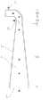
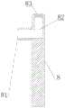
图1为实施例一中所述喷气剥离电切头的结构示意图(主侧视图);1 is a schematic structural diagram (main side view) of the jet stripping electric cutting head described in
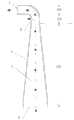
图2为实施例一中所述喷气剥离电切头的结构示意图(主侧剖视图,金属管体侧壁上设有出气端口);Fig. 2 is the structural schematic diagram of the jet stripping electric cutting head described in the first embodiment (the main side cross-sectional view, the side wall of the metal pipe body is provided with an air outlet port);
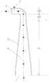
图3为实施例一中所述喷气剥离电切头的结构示意图(主侧剖视图);Fig. 3 is the structural schematic diagram (main side cross-sectional view) of the jet stripping electric cutting head described in the first embodiment;
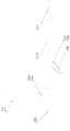
图4为实施例一中所述用于腹腔镜手术的喷气剥离电切装置的结构示意图(主视侧视图);4 is a schematic structural diagram (front side view) of the jet stripping electrosurgical device for laparoscopic surgery described in
图5为实施例一中所述手柄的结构示意图(主侧剖视图);5 is a schematic structural diagram of the handle described in Embodiment 1 (main side cross-sectional view);
图6为实施例一中所述喷气剥离电切头的结构示意图(主侧剖视图);6 is a schematic structural diagram (main side cross-sectional view) of the jet stripping electric cutting head described in
图7为实施例一中所述喷气剥离电切头的结构示意图(仰视图);Fig. 7 is the structural representation (bottom view) of the jet stripping electric cutting head described in the first embodiment;
图8为实施例二中所述喷气剥离电切头的结构示意图(主侧视图);8 is a schematic structural diagram (main side view) of the jet stripping electric cutting head described in the second embodiment;
图9为实施例三中所述喷气剥离电切头的结构示意图(主视剖视图);Fig. 9 is the structural schematic diagram (front cross-sectional view) of the jet stripping electric cutting head described in Example 3;
图10为实施例三中所述喷气剥离电切头的结构示意图(主视剖视图);Fig. 10 is the structural representation (front cross-sectional view) of the jet stripping electric cutting head described in the third embodiment;
图11为实施例四中的喷气剥离电切头的结构示意图(主视剖视图);Fig. 11 is the structural representation (front sectional view) of the jet stripping electric cutting head in the fourth embodiment;
图12为实施例五中的所述用于腹腔镜手术的喷气剥离电切装置的结构示意图(主视侧视图);FIG. 12 is a schematic structural diagram (front side view) of the jet stripping electrosurgical cutting device for laparoscopic surgery in the fifth embodiment;
图13为实施例五中所述手柄的结构示意图(主侧剖视图);13 is a schematic structural diagram of the handle described in Embodiment 5 (main side cross-sectional view);
上述图中的箭头表示气体流动方向。The arrows in the above figures indicate the direction of gas flow.
附图标记说明:Description of reference numbers:
1、金属管体;4、气体流道;2、进气端口;3、出气端口;101、连接段;102、过渡段;103、弯折段;6、过渡段喷气口;7、金属输气管;8、手柄;9、导电柱;10、导电柱绝缘套;81、输气入口;82、输气流道;83、输气出口。1. Metal pipe body; 4. Gas flow channel; 2. Air inlet port; 3. Air outlet port; 101. Connecting section; 102. Transition section; 103. Bending section; 6. Air jet port in transition section; 7.
具体实施方式Detailed ways
下面将结合附图对本发明的技术方案进行清楚、完整地描述,显然,所描述的实施例是本发明一部分实施例,而不是全部的实施例。基于本发明中的实施例,本领域普通技术人员在没有做出创造性劳动前提下所获得的所有其他实施例,都属于本发明保护的范围。The technical solutions of the present invention will be clearly and completely described below with reference to the accompanying drawings. Obviously, the described embodiments are a part of the embodiments of the present invention, but not all of the embodiments. Based on the embodiments of the present invention, all other embodiments obtained by those of ordinary skill in the art without creative efforts shall fall within the protection scope of the present invention.
在本发明的描述中,需要说明的是,术语“中心”、“上”、“下”、“左”、“右”、“竖直”、“水平”、“内”、“外”等指示的方位或位置关系为基于附图所示的方位或位置关系,仅是为了便于描述本发明和简化描述,而不是指示或暗示所指的装置或元件必须具有特定的方位、以特定的方位构造和操作,因此不能理解为对本发明的限制。此外,术语“第一”、“第二”、“第三”仅用于描述目的,而不能理解为指示或暗示相对重要性。In the description of the present invention, it should be noted that the terms "center", "upper", "lower", "left", "right", "vertical", "horizontal", "inner", "outer", etc. The indicated orientation or positional relationship is based on the orientation or positional relationship shown in the accompanying drawings, which is only for the convenience of describing the present invention and simplifying the description, rather than indicating or implying that the indicated device or element must have a specific orientation or a specific orientation. construction and operation, and therefore should not be construed as limiting the invention. Furthermore, the terms "first", "second", and "third" are used for descriptive purposes only and should not be construed to indicate or imply relative importance.
在本发明的描述中,需要说明的是,除非另有明确的规定和限定,术语“安装”、“相连”、“连接”、“连通”应做广义理解,例如,可以是固定连接,也可以是可拆卸连接,或一体地连接;可以是机械连接,也可以是电连接;可以是直接相连,也可以通过中间媒介间接相连,可以是两个元件内部的连通,也可以是电焊连接。对于本领域的普通技术人员而言,可以具体情况理解上述术语在本发明中的具体含义。In the description of the present invention, it should be noted that the terms "installed", "connected", "connected" and "connected" should be understood in a broad sense, unless otherwise expressly specified and limited, for example, it may be a fixed connection, or It can be a detachable connection or an integral connection; it can be a mechanical connection or an electrical connection; it can be a direct connection or an indirect connection through an intermediate medium, and it can be the internal connection of two components, or it can be an electric welding connection. For those of ordinary skill in the art, the specific meanings of the above terms in the present invention can be understood in specific situations.
实施例一Example 1
如图1、图2所示,本实施例提供了一种喷气剥离电切头,包括内设气体流道4的金属管体1,金属管体1一端封闭,另一端设有与气体流道4连通的进气端口2,金属管体1封闭处或/和紧靠金属管体1封闭处的金属管体1的外侧壁上开设有与气体流道4连通的出气端口3;气体流道4的内直径由进气端口2向出气端口3逐渐减小或阶梯式减小;本实施具体的方案为紧靠金属管体1封闭处的金属管体1的外侧壁上开设有一个与气体流道4连通的出气端口3。As shown in FIG. 1 and FIG. 2 , this embodiment provides a jet stripping electric cutting head, which includes a
本发明通过金属管体1一端封闭,另一端设有与气体流道4连通的进气端口2,金属管体1封闭处或/和紧靠金属管体1封闭处的金属管体1的外侧壁上开设有与气体流道4连通的出气端口3;气体流道4的内直径由进气端口2向出气端口3逐渐减小或阶梯式减小;本实施具体的方案为紧靠金属管体1封闭处的金属管体1的外侧壁上开设有一个与气体流道4连通的出气端口3的设计,目的提升气体的流速,让气体从气体流道4通过后,出气端口3喷出时,使得气体流速成倍增加,从而增加气体喷出的动能,通过金属管体1结构的设计,可以将气体流道4内气体的流速呈倍提升,从而喷出一定动能的气体有助于对腹腔深部以及彼此粘连紧密组织脏器的分离,吹开腹腔内潜在间隙,方便操作者进行高效、精准和安全的解剖操作,与现有腹腔镜手术器械相比,具有解剖剥离更精准,操作性更便捷和安全性更高的优点。In the present invention, one end of the
本发明根据质量守恒和能量守恒定律,通过伯努利方程计算,进气端口2内直径和出气端口3内直径遵从下方规律,即可有效的提高气体流速,保证吹出的气体具有一定的动能,从而保证脏器的分离,进气端口2内直径标记为d进和出气端口3内直径标记为d出;d出=0.68*d进/5。According to the law of mass conservation and energy conservation, the invention calculates by Bernoulli equation, and the inner diameter of the
如图1、图2所示,本实施例金属管体1从下到上依次包括连接段101,与连接段101顶部连接的过渡段102,与过渡段102顶部连接的弯折段103,过渡段102和弯折段103间的夹角a为90°-180°,本实施例优选的角度为夹角a为90°;其中,连接段101的纵向剖面为梯形或方形,本实施例连接段101的纵向剖面为梯形;出气端口3设于弯折段103上;连接段101和过渡段102外壁均涂有绝缘涂层。As shown in FIG. 1 and FIG. 2 , the
本发明通过金属管体1从下到上依次包括连接段101,与连接段101顶部连接的过渡段102,与过渡段102顶部连接的弯折段103,过渡段102和弯折段103间的夹角a为90°-180°,本实施例优选的角度为夹角a为90°;其中,连接段101的纵向剖面为梯形或方形,本实施例的连接段101的纵向剖面为梯形;出气端口3设于弯折段103上;连接段101和过渡段102外壁均涂有绝缘涂层的设计,将金属管体1划分为三段结构,可以根据实际情况任选夹角a的角度,达到方便操作的目的,同时,方便绝缘涂层的设置,在保护金属管体1的同时,起到绝缘电的作用,避免在电切过程中,损伤不需要治疗的脏器,提高手术的安全系数;连接段101的纵向剖面为梯形,使得气体流道4内的气体流速持续提高,保证气流的输送速度,有助于对腹腔深部以及彼此粘连紧密组织脏器的分离,吹开腹腔内潜在间隙,方便操作者进行高效、精准和安全的解剖操作。In the present invention, the
如图3所示,本实施例过渡段103的侧壁上设有与气体流道4连通的过渡段喷气口6;过渡段喷气口6与出气端口3同侧设置;过渡段喷气口6的内直径为0.1-10mm。As shown in FIG. 3 , the side wall of the
本发明通过过渡段103的侧壁上设有与气体流道4连通的过渡段喷气口6;过渡段喷气口6与出气端口3同侧设置;过渡段喷气口6的内直径为0.1-10mm的设计,增加了气体出口,即过渡段喷气口6,可以多角度,多位置的喷射出气体,有助于对腹腔深部以及彼此粘连紧密组织脏器的分离,吹开腹腔内潜在间隙,方便操作者进行高效、精准和安全的解剖操作。In the present invention, the side wall of the
本发明的进气端口2的内直径为1.5mm-15mm;出气端口3的内直径为0.1mm-10mm;金属管体1的高度为5mm-50mm;根据腹腔镜手术穿刺筒的内径,进行进气端口2、出气端口3的内直径为选择尺寸,在尺寸的选择上,要保证出气端口3小于进气端口2。The inner diameter of the
如图4、图5所示,本实施例还包括一种喷气剥离电切装置,包括金属输气管7,金属输气管7的一端安装连通有如上述中任一项所述的喷气剥离电切头,另一端安装有与金属输气管7可拆卸连接的手柄8;金属输气管7的侧壁上设有导电柱9;手柄8上设有与气源连通的输气入口81和与金属输气管7连通的输气出口83,手柄8内部设有与输气入口81和输气出口83均连通的输气流道82,手柄8的输气入口81与气管11连通;导电柱9通过电线与电切电凝装置电连接。As shown in Figure 4 and Figure 5, the present embodiment also includes a jet stripping electric cutting device, including a metal
本发明通过金属输气管7的一端安装连通有如上述中任一项所述的喷气剥离电切头,另一端安装有与金属输气管7可拆卸连接的手柄8;金属输气管7的侧壁上设有导电柱9;手柄8上设有与气源连通的输气入口81和与金属输气管7连通的输气出口83,手柄8内部设有与输气入口81和输气出口83均连通的输气流道82,手柄8的输气入口81与气管11连通;导电柱9通过电线与电切电凝装置电连接的设计,喷气剥离电切头、金属输气管7和手柄8三个结构结合,方便操作者手持操作,金属输气管7和手柄8可拆卸连接,方便安装和拆卸清洗,同时金属输气管7可以选择多种长度,方便操作者根据治疗的患者,选用相应的尺寸的金属输气管7,提高手术效率,保证手术安全;手柄8可以选用金属,方便消毒,也可以选用塑料,质量轻,可以制备一次性手柄,保证手柄8的清洁性,手柄8可以根据手持方式,设计多种造型,可以设置成圆柱形,方形等,提高操作者的手持舒适度,缓解操作者手术过程中的疲劳。In the present invention, one end of the metal
本发明喷气剥离电切头与金属输气管7连接方式可以焊接,或者一体成型,或者螺纹连接,根据具体情况,相应的选择连接方式。The connection mode of the jet stripping electric cutting head of the present invention and the metal
本发明输气入口81的中心纵轴线与金属输气管7中心纵轴线重合,保障气体流通的顺畅性,避免操作过程中由于金属输气管7旋转,导致与输气入口81连接的气管11的弯折。The central longitudinal axis of the
本发明金属输气管7外壁设有绝缘层;导电柱9与金属输气管7连接处设有外套于导电柱9的导电柱绝缘套10,提高金属输气管7耐腐蚀度,同时保证金属输气管7电绝缘性,保护操作者和治疗者的生命安全。In the present invention, the outer wall of the metal
本发明手柄8外设有绝缘层,起到防腐蚀和电绝缘的作用;手柄8的材质为金属或塑料,本实施例选用塑料制备手柄8,可以制备一次性手术用具,保障手术的安全性。The
本发明金属输气管7一端设有外螺纹,输气出口83内壁上设有内螺纹,金属输气管7螺接于输气出口83上,连接方式简单,制备方便,便于批量生产。One end of the metal
本发明金属输气管7的长度为200mm-400mm,可以根据实际情况选择金属输气管7的长度。The length of the metal
本发明输气入口81、输气流道82及输气出口83的内直径均大于金属输气管7的内直径,实现气体流速的增加,保证气体喷出的动能。The inner diameter of the
本发明输气入口81与气管11连接方式包括套接,当手柄8材质为塑料是,可以将输气入口81与气管11采用热熔方式连接。The connection method of the
如图6、图7所示,本实施例中的金属管体1内部设有金属管体5,金属管体5的外壁与金属管体1的内壁焊接于一体,金属管体5两端分别设有入口51和出口52,进口51与进气端口2连通,出口52与出气端口3连通,入口51的直径大于出口52的直径,出口52的直径大于出气端口3的直径。As shown in FIG. 6 and FIG. 7 , the
本发明通过金属管体1内部设有金属管体5,金属管体5的外壁与金属管体1的内壁焊接于一体,金属管体5两端分别设有入口51和出口52,进口51与进气端口2连通,出口52与出气端口3连通,入口51的直径大于出口52的直径,出口52的直径大于出气端口3的直径的设计,在金属管体1通过外加金属管体5进一步改变金属管体1内部气体流道4直径,提高气体的流速,满足需要喷出的动能,保证对腹腔深部以及彼此粘连紧密组织脏器的分离,吹开腹腔内潜在间隙,方便操作者进行高效、精准和安全的解剖操作。In the present invention, a
实施例二
如图8所示,本发明中所述金属管体1是在实施例一基础上的改进,实施例一中公开的技术内容不重复描述,实施例一公开的内容也属于本实施例公开的内容。As shown in FIG. 8 , the
本实施例连接段101的纵向剖面为方形。The longitudinal section of the connecting
本发明通过连接段101的纵向剖面为方形的设计,保证金属管体1的进气量,保证对脏器的有效分离,同时连接段101的纵向剖面为长方形的设计,方便加工,101的纵向剖面可以为长方形或者正方形。In the present invention, the longitudinal section of the connecting
实施例三
本实施例与实施例一区别仅仅在于出气端口3的开设位置,实施例一中公开的技术内容不重复描述,实施例一公开的内容也属于本实施例公开的内容。The only difference between this embodiment and the first embodiment is the opening position of the
如图9所示,本实施例提供了一种喷气剥离电切头,包括内设气体流道4的金属管体1,金属管体1一端封闭,另一端设有与气体流道4连通的进气端口2,金属管体1封闭处或/和紧靠金属管体1封闭处的金属管体1的外侧壁上开设有与气体流道4连通的出气端口3;气体流道4的内直径由进气端口2向出气端口3逐渐减小或阶梯式减小;本实施具体的方案为金属管体1封闭处开设有一个出气端口3。As shown in FIG. 9 , this embodiment provides a jet stripping electric cutting head, including a
本发明通过金属管体1一端封闭,另一端设有与气体流道4连通的进气端口2,金属管体1封闭处或/和紧靠金属管体1封闭处的金属管体1的外侧壁上开设有与气体流道4连通的出气端口3;气体流道4的内直径由进气端口2向出气端口3逐渐减小或阶梯式减小;本实施具体的方案为金属管体1封闭处开设有一个出气端口3的设计,区别于实施例一,本方案在封闭处开始出气端口3,可以针对某一局部特殊位置的脏器进行喷气,分离出脏器间存在的间隙,方便操作,提高手术安全系数。In the present invention, one end of the
如图10所示,本实施例过渡段103的侧壁上设有与气体流道4连通的过渡段喷气口6;过渡段喷气口6与出气端口3同侧设置;过渡段喷气口6的内直径为0.1-10mm。As shown in FIG. 10 , the side wall of the
本发明通过进一步的在过渡段103的侧壁上设有与气体流道4连通的过渡段喷气口6;过渡段喷气口6与出气端口3同侧设置;过渡段喷气口6的内直径为0.1-10mm的设计,目的是多角度的喷射,同样,可以针对某一局部特殊位置的脏器进行喷气,分离出脏器间存在的间隙,方便操作,提高手术安全系数。In the present invention, the side wall of the
实施例四
本实施例与实施例一区别仅仅在于出气端口3的开设位置,实施例一中公开的技术内容不重复描述,实施例一公开的内容也属于本实施例公开的内容。The only difference between this embodiment and the first embodiment is the opening position of the
如图11所示,本实施例提供了一种喷气剥离电切头,包括内设气体流道4的金属管体1,金属管体1一端封闭,另一端设有与气体流道4连通的进气端口2,金属管体1封闭处或/和紧靠金属管体1封闭处的金属管体1的外侧壁上开设有与气体流道4连通的出气端口3;气体流道4的内直径由进气端口2向出气端口3逐渐减小或阶梯式减小;本实施具体的方案为金属管体1封闭处和紧靠金属管体1封闭处的金属管体1的外侧壁上均开设有与气体流道4连通的出气端口3。As shown in FIG. 11 , this embodiment provides a jet stripping electric cutting head, including a
本发明通过金属管体1一端封闭,另一端设有与气体流道4连通的进气端口2,金属管体1封闭处或/和紧靠金属管体1封闭处的金属管体1的外侧壁上开设有与气体流道4连通的出气端口3;气体流道4的内直径由进气端口2向出气端口3逐渐减小或阶梯式减小;本实施具体的方案为金属管体1封闭处和紧靠金属管体1封闭处的金属管体1的外侧壁上均开设有与气体流道4连通的出气端口3的设计,目的是实现可以针对某一局部特殊位置的脏器进行喷气,分离出脏器间存在的间隙,方便操作,提高手术安全系数。In the present invention, one end of the
实施例五
本实施例与实施例一区别仅仅在于输气入口81的设置位置,实施例一中公开的技术内容不重复描述,实施例一公开的内容也属于本实施例公开的内容。The only difference between this embodiment and the first embodiment is the setting position of the
如图12、图13所示,输气入口81与导电柱9分设于输气金属管7两侧。As shown in FIG. 12 and FIG. 13 , the
本发明通过输气入口81与导电柱9分设于输气金属管7两侧的设计,方便操作者观察连接情况,避免气管或者电线分别输气入口81与导电柱9脱落,影响手术进程。The present invention adopts the design that the
最后应说明的是:以上各实施例仅用以说明本发明的技术方案,而非对其限制;尽管参照前述各实施例对本发明进行了详细的说明,本领域的普通技术人员应当理解:其依然可以对前述各实施例所记载的技术方案进行修改,或者对其中部分或者全部技术特征进行等同替换;而这些修改或者替换,并不使相应技术方案的本质脱离本发明各实施例技术方案的范围。Finally, it should be noted that the above embodiments are only used to illustrate the technical solutions of the present invention, but not to limit them; although the present invention has been described in detail with reference to the foregoing embodiments, those of ordinary skill in the art should understand that: The technical solutions described in the foregoing embodiments can still be modified, or some or all of the technical features thereof can be equivalently replaced; and these modifications or replacements do not make the essence of the corresponding technical solutions deviate from the technical solutions of the embodiments of the present invention. scope.
Claims (10)
Priority Applications (1)
| Application Number | Priority Date | Filing Date | Title |
|---|---|---|---|
| CN201910945247.3ACN110664480A (en) | 2019-09-30 | 2019-09-30 | Jet stripping electric cutting head and jet stripping electric cutting device |
Applications Claiming Priority (1)
| Application Number | Priority Date | Filing Date | Title |
|---|---|---|---|
| CN201910945247.3ACN110664480A (en) | 2019-09-30 | 2019-09-30 | Jet stripping electric cutting head and jet stripping electric cutting device |
Publications (1)
| Publication Number | Publication Date |
|---|---|
| CN110664480Atrue CN110664480A (en) | 2020-01-10 |
Family
ID=69080828
Family Applications (1)
| Application Number | Title | Priority Date | Filing Date |
|---|---|---|---|
| CN201910945247.3APendingCN110664480A (en) | 2019-09-30 | 2019-09-30 | Jet stripping electric cutting head and jet stripping electric cutting device |
Country Status (1)
| Country | Link |
|---|---|
| CN (1) | CN110664480A (en) |
Citations (9)
| Publication number | Priority date | Publication date | Assignee | Title |
|---|---|---|---|---|
| JP2000262528A (en)* | 1999-03-19 | 2000-09-26 | Sugino Mach Ltd | Laparoscopic surgery method and surgical device |
| US20090076505A1 (en)* | 2007-09-13 | 2009-03-19 | Arts Gene H | Electrosurgical instrument |
| CN101404943A (en)* | 2006-03-16 | 2009-04-08 | 土耳其科学技术研究理事会 | Compressed air dissector (air jet scraper) |
| US20110118717A1 (en)* | 2009-11-06 | 2011-05-19 | Tsunami Medtech, Llc | Tissue ablation systems and methods of use |
| US20170231655A1 (en)* | 2010-02-04 | 2017-08-17 | Procept Biorobotics Corporation | Fluid jet tissue resection and cold coagulation (aquablation) methods and apparatus |
| CN107049474A (en)* | 2017-03-30 | 2017-08-18 | 吴彬 | One kind electric knife of tissue separation and its method of work |
| CN107865683A (en)* | 2016-09-27 | 2018-04-03 | 惠州科赛医疗有限公司 | Nozzle, water knife apparatus, nozzle forming method and water knife apparatus forming method |
| KR20190103746A (en)* | 2018-02-28 | 2019-09-05 | 강은희 | Apparatus and medical procedure for cellulite improving |
| CN211067000U (en)* | 2019-09-30 | 2020-07-24 | 严立 | A kind of jet stripping electric cutting head and jet stripping electric cutting device |
- 2019
- 2019-09-30CNCN201910945247.3Apatent/CN110664480A/enactivePending
Patent Citations (9)
| Publication number | Priority date | Publication date | Assignee | Title |
|---|---|---|---|---|
| JP2000262528A (en)* | 1999-03-19 | 2000-09-26 | Sugino Mach Ltd | Laparoscopic surgery method and surgical device |
| CN101404943A (en)* | 2006-03-16 | 2009-04-08 | 土耳其科学技术研究理事会 | Compressed air dissector (air jet scraper) |
| US20090076505A1 (en)* | 2007-09-13 | 2009-03-19 | Arts Gene H | Electrosurgical instrument |
| US20110118717A1 (en)* | 2009-11-06 | 2011-05-19 | Tsunami Medtech, Llc | Tissue ablation systems and methods of use |
| US20170231655A1 (en)* | 2010-02-04 | 2017-08-17 | Procept Biorobotics Corporation | Fluid jet tissue resection and cold coagulation (aquablation) methods and apparatus |
| CN107865683A (en)* | 2016-09-27 | 2018-04-03 | 惠州科赛医疗有限公司 | Nozzle, water knife apparatus, nozzle forming method and water knife apparatus forming method |
| CN107049474A (en)* | 2017-03-30 | 2017-08-18 | 吴彬 | One kind electric knife of tissue separation and its method of work |
| KR20190103746A (en)* | 2018-02-28 | 2019-09-05 | 강은희 | Apparatus and medical procedure for cellulite improving |
| CN211067000U (en)* | 2019-09-30 | 2020-07-24 | 严立 | A kind of jet stripping electric cutting head and jet stripping electric cutting device |
Similar Documents
| Publication | Publication Date | Title |
|---|---|---|
| JP5622838B2 (en) | Endoscopic surgical instrument | |
| AU2006252010B2 (en) | Laparoscopic apparatus for performing electrosurgical procedures | |
| EP2077807B1 (en) | Surgical instrument for coagulation and suction | |
| CN103536351B (en) | A kind of low-temperature plasma electrode assembly for hals,Nasen und Ohrenheilkunde | |
| JP2003520078A (en) | Liquid jet operated surgical instruments | |
| US9011426B2 (en) | Flexible electrosurgical ablation and aspiration electrode with beveled active surface | |
| CN211067000U (en) | A kind of jet stripping electric cutting head and jet stripping electric cutting device | |
| CN107137140A (en) | A kind of low-temperature plasma Otorhinolaryngologic operation knife | |
| CN110664480A (en) | Jet stripping electric cutting head and jet stripping electric cutting device | |
| US8992521B2 (en) | Flexible electrosurgical ablation and aspiration electrode with beveled active surface | |
| CN211484872U (en) | Jet stripping system and foot-controlled gas flow rate device for controlling gas supply device in jet stripping system | |
| CN212326556U (en) | Air jet stripping system and gas flow rate adjusting device for controlling gas supply device | |
| CN201899559U (en) | Smoke suction LEEP (loop electrosurgical excision procedure) knife | |
| CN110664479A (en) | Gas flow rate adjusting device for controlling gas supply device and jet stripping system | |
| CN110179536A (en) | A kind of smoke abatement, anti-eschar adhesion laparoscope electric coagulation stick | |
| CN210077842U (en) | A smokeless electrocautery for multi-angle smoking | |
| CN212308026U (en) | Smoke control electric coagulation knife | |
| CN204121166U (en) | A Plasma Surgical Electrode with Inclined Micropore Liquid Supply | |
| CN206822706U (en) | A kind of high-frequency electrical cutter head of band protection baffle plate | |
| CN110711024B (en) | Foot-controlled gas flow rate device for controlling gas supply device and jet stripping system | |
| CN207708021U (en) | Smoke removing device in a kind of operation | |
| CN221830772U (en) | Flow-controllable radiofrequency ablation electrode device | |
| CN220175227U (en) | An electrosurgical scalpel | |
| CN205626098U (en) | Side is inhaled formula peritoneoscope power consumption and is congealed stick | |
| CN213851020U (en) | A bipolar coagulator |
Legal Events
| Date | Code | Title | Description |
|---|---|---|---|
| PB01 | Publication | ||
| PB01 | Publication | ||
| SE01 | Entry into force of request for substantive examination | ||
| SE01 | Entry into force of request for substantive examination | ||
| TA01 | Transfer of patent application right | ||
| TA01 | Transfer of patent application right | Effective date of registration:20230118 Address after:100005 No.1 dongjiaomin lane, Dongcheng District, Beijing Applicant after:BEIJING TONGREN HOSPITAL, CAPITAL MEDICAL University Address before:100032 Langqinyuan, No.1, handkerchief South Street, guanganmenwai, Xicheng District, Beijing Applicant before:Yan Li |