CN110658591A - Connector contact module and connector - Google Patents
Connector contact module and connectorDownload PDFInfo
- Publication number
- CN110658591A CN110658591ACN201811571020.9ACN201811571020ACN110658591ACN 110658591 ACN110658591 ACN 110658591ACN 201811571020 ACN201811571020 ACN 201811571020ACN 110658591 ACN110658591 ACN 110658591A
- Authority
- CN
- China
- Prior art keywords
- module
- connector
- contact
- annular
- shell
- Prior art date
- Legal status (The legal status is an assumption and is not a legal conclusion. Google has not performed a legal analysis and makes no representation as to the accuracy of the status listed.)
- Pending
Links
Images


Classifications
- G—PHYSICS
- G02—OPTICS
- G02B—OPTICAL ELEMENTS, SYSTEMS OR APPARATUS
- G02B6/00—Light guides; Structural details of arrangements comprising light guides and other optical elements, e.g. couplings
- G02B6/24—Coupling light guides
- G02B6/36—Mechanical coupling means
- G02B6/38—Mechanical coupling means having fibre to fibre mating means
- G02B6/3807—Dismountable connectors, i.e. comprising plugs
- G02B6/3833—Details of mounting fibres in ferrules; Assembly methods; Manufacture
- G02B6/3847—Details of mounting fibres in ferrules; Assembly methods; Manufacture with means preventing fibre end damage, e.g. recessed fibre surfaces
- G02B6/3849—Details of mounting fibres in ferrules; Assembly methods; Manufacture with means preventing fibre end damage, e.g. recessed fibre surfaces using mechanical protective elements, e.g. caps, hoods, sealing membranes
Landscapes
- Physics & Mathematics (AREA)
- General Physics & Mathematics (AREA)
- Optics & Photonics (AREA)
- Connector Housings Or Holding Contact Members (AREA)
Abstract
Description
Translated fromChinese技术领域technical field
本发明涉及连接器的接触件模块及连接器。The present invention relates to a contact module of a connector and a connector.
背景技术Background technique
为了保证传输质量,连接器往往需要设置防尘结构,特别是光纤连接器。光纤连接器传输光信号的基本原理是:两个光纤插芯端面的精密对接实现光信号的耦合。光纤插芯核心区域纤芯直径一般仅有9um~62.5um,灰尘(常见PM2.5或者PM10)如果在接触区域就会对光信号通路造成遮挡,使IL(插入损耗)增大。光纤连接的位置对灰尘非常敏感,所以对接端面的防尘非常重要。In order to ensure transmission quality, connectors often need to be provided with dust-proof structures, especially optical fiber connectors. The basic principle of optical signal transmission by optical fiber connector is: the precise butt joint of the end faces of two optical fiber ferrules realizes the coupling of optical signals. The diameter of the fiber core in the core area of the optical fiber ferrule is generally only 9um to 62.5um. If dust (commonly PM2.5 or PM10) is in the contact area, it will block the optical signal path and increase the IL (insertion loss). The position of the optical fiber connection is very sensitive to dust, so the dustproof of the mating end face is very important.
光纤连接器用于设备柜体内时,由于设备柜体上设有用于散热的风扇,而风扇运转时会带动携带有灰尘的气流在设备内部循环流动,使得光纤连接器附近持续有流动的空气(携带灰尘),连接器外壳之间如果有缝隙,或者在连接器插拔的瞬间,流动的空气携带的灰尘很容易进入连接器内部,很可能污染到插芯端面,造成插入损耗变大。When the optical fiber connector is used in the equipment cabinet, since the equipment cabinet is equipped with a fan for heat dissipation, and when the fan is running, it will drive the airflow carrying dust to circulate inside the equipment, so that there is continuous flowing air near the optical fiber connector (carrying Dust), if there is a gap between the connector shells, or at the moment when the connector is plugged and unplugged, the dust carried by the flowing air can easily enter the interior of the connector, which is likely to contaminate the end face of the ferrule, resulting in increased insertion loss.
为了实现连接器的防尘,现有技术中提出了在连接器的插接口设置防尘门的技术方案,例如授权公告号为CN106299841B的中国专利公开的连接器采用的防尘门。现有技术中还有在接触件模块的插接端设置防尘门的技术方案,如公布号为CN105024219A的中国专利申请中公开的连接器所采用的防尘板。现有的上述连接器中的防尘门的能够对连接器壳内设置的接触件模块进行遮挡,起到防尘作用。但是,现有的连接器的接触件模块往往是插设在连接器壳上设置的模块容纳腔内,并且大部分接触件模块需要能够实现插拔以便于装配和维护,为了实现接触件模块的插拔,接触件模块的模块壳体与模块容纳腔的腔壁之间需要有一定配合间隙,连接器使用过程中,灰尘容易从该配合间隙内进入连接器壳,进而会对接触件模块中的接触件造成污染,影响连接器的性能。In order to realize the dustproof of the connector, the prior art proposes a technical solution of arranging a dustproof door at the plug-in interface of the connector, such as the dustproof door used in the connector disclosed in the Chinese Patent with the Authorization Bulletin No. CN106299841B. In the prior art, there is also a technical solution of arranging a dustproof door at the plug-in end of the contact module, such as the dustproof plate used in the connector disclosed in the Chinese Patent Application Publication No. CN105024219A. The dust-proof door in the existing connector can shield the contact module provided in the connector housing, and play a role of dust-proof. However, the contact module of the existing connector is often inserted into the module accommodating cavity provided on the connector shell, and most of the contact modules need to be able to be plugged and unplugged to facilitate assembly and maintenance. When plugging and unplugging, there needs to be a certain matching gap between the module shell of the contact module and the cavity wall of the module accommodating cavity. During the use of the connector, dust can easily enter the connector shell from the matching gap, which will cause damage to the contact module. The contacts cause contamination and affect the performance of the connector.
发明内容SUMMARY OF THE INVENTION
本发明的目的是提供一种连接器的接触件模块,以解决现有技术中灰尘容易从接触件模块与连接器壳之间的间隙进入而污染接触件的问题。本发明的另一个目的是提供一种连接器,解决现有技术中灰尘容易从接触件模块与连接器壳之间的间隙进入而影响连接器性能的问题。The purpose of the present invention is to provide a contact piece module of a connector, so as to solve the problem in the prior art that dust easily enters from the gap between the contact piece module and the connector housing to contaminate the contact piece. Another object of the present invention is to provide a connector that solves the problem in the prior art that dust easily enters from the gap between the contact module and the connector housing and affects the performance of the connector.
本发明中连接器的接触件模块采用的技术方案如下。The technical solution adopted by the contact module of the connector in the present invention is as follows.
连接器的接触件模块,包括供相应的接触件连接的模块壳体,所述模块壳体的外周面上设有用于与连接器壳上的模块容纳腔的腔内壁接触以阻挡灰尘的环形防尘圈。The contact piece module of the connector includes a module housing for connecting the corresponding contact pieces, the outer peripheral surface of the module housing is provided with an annular anti-dust for contacting with the cavity inner wall of the module accommodating cavity on the connector housing to block dust. dust ring.
有益效果:接触件模块插入模块连接器壳上的模块容纳腔时,模块壳体的外周面上设置环形防尘圈能够与模块容纳腔的腔内壁接触,从而阻挡灰尘进入,与现有技术相比,能够提高接触件模块的防尘性能,避免灰尘从接触件模块与连接器壳之间的间隙进入而污染接触件。Beneficial effects: when the contact module is inserted into the module accommodating cavity on the module connector shell, the annular dust ring provided on the outer peripheral surface of the module shell can contact the inner wall of the module accommodating cavity, thereby blocking the entry of dust, which is consistent with the prior art. The dustproof performance of the contact piece module can be improved, and dust can be prevented from entering from the gap between the contact piece module and the connector housing to contaminate the contact piece.
作为一种优选的技术方案:所述模块壳体的外周面上设有环槽,所述环形防尘圈设置在环槽内,环形防尘件的外周面高于模块壳体的外周面。As a preferred technical solution, an annular groove is provided on the outer peripheral surface of the module housing, the annular dustproof ring is arranged in the annular groove, and the outer peripheral surface of the annular dustproof member is higher than the outer peripheral surface of the module housing.
有益效果:设置环槽能够保证环形防尘圈的径向尺寸,并且能够避免造成模块壳体的整体外形产生较大变化。Beneficial effects: the provision of the ring groove can ensure the radial size of the annular dust ring, and can avoid causing a large change in the overall shape of the module housing.
作为一种优选的技术方案:所述环形防尘圈的侧壁与所述环槽的槽侧壁接触。As a preferred technical solution: the side wall of the annular dust ring is in contact with the side wall of the groove of the ring groove.
有益效果:该结构能够对环形防尘圈进行良好定位,便于接触件模块的插接。Beneficial effects: the structure can well position the annular dust ring, which facilitates the plugging of the contact module.
作为一种优选的技术方案:所述环形防尘圈的外周面与侧壁的连接处设有倒角。As a preferred technical solution: the connection between the outer peripheral surface of the annular dust ring and the side wall is provided with a chamfer.
作为一种优选的技术方案:所述环形防尘圈的各向外周面均为平面。As a preferred technical solution: each outer peripheral surface of the annular dust ring is flat.
有益效果:采用该方案能够避免提高环形防尘圈与模块壳体的结合面积,保证防护效果。Beneficial effects: By adopting this solution, it is possible to avoid increasing the combined area of the annular dust ring and the module housing, and to ensure the protection effect.
作为一种优选的技术方案:所述环形防尘圈由套设在模块壳体上的环体形成。As a preferred technical solution: the annular dust ring is formed by a ring body sleeved on the module housing.
有益效果:采用环体形式的环形防尘圈结构简单,安装方便。Beneficial effects: the annular dust ring in the form of a ring body has a simple structure and is easy to install.
作为一种优选的技术方案:所述环形防尘圈由注塑成型在模块壳体上的环体形成。As a preferred technical solution: the annular dust ring is formed by a ring body that is injection-molded on the module housing.
作为一种优选的技术方案:模块壳体具有用于在插接到位时与模块容纳腔的模块插入端的内壁对应的插入端对应部,所述环形防尘圈设置在所述插入端对应部处。As a preferred technical solution: the module housing has an insertion end corresponding portion corresponding to the inner wall of the module insertion end of the module accommodating cavity when it is inserted into place, and the annular dust ring is arranged at the insertion end corresponding portion .
有益效果:采用该方案能够将灰尘阻挡在模块容纳腔的腔口处,避免灰尘进入模块容纳腔深处。Beneficial effects: By adopting this solution, dust can be blocked at the cavity mouth of the module accommodating cavity, and dust can be prevented from entering the depth of the module accommodating cavity.
上述各优选的技术方案可以单独采用,在能够组合的情况下也可以两种以上任意组合采用。The above-mentioned preferred technical solutions can be used alone, or two or more of them can be used in any combination if they can be combined.
本发明中连接器采用的技术方案如下。The technical solution adopted by the connector in the present invention is as follows.
连接器,包括连接器壳和接触件模块,连接器壳上设有供接触件模块插入的模块容纳腔,接触件模块包括供相应的接触件连接的模块壳体,所述模块壳体的外周面与所述模块容纳腔的腔内壁之间设有用以阻挡灰尘的环形防尘圈。The connector includes a connector shell and a contact module. The connector shell is provided with a module accommodating cavity for the contact module to be inserted into. The contact module includes a module housing for connecting the corresponding contacts. The outer periphery of the module housing is An annular dust ring for blocking dust is arranged between the surface and the inner wall of the module accommodating cavity.
有益效果:接触件模块插入模块连接器壳上的模块容纳腔时,所述模块壳体的外周面与所述模块容纳腔的腔内壁之间的环形防尘圈能够封堵模块壳体与模块容纳腔之间的间隔,从而阻挡灰尘进入,与现有技术相比,能够避免灰尘从接触件模块与连接器壳之间的间隙进入而影响连接器性能。Beneficial effect: when the contact module is inserted into the module accommodating cavity on the module connector shell, the annular dust ring between the outer peripheral surface of the module shell and the cavity inner wall of the module accommodating cavity can block the module shell and the module The space between the accommodating cavities prevents dust from entering, and compared with the prior art, dust can be prevented from entering from the gap between the contact module and the connector housing to affect the performance of the connector.
作为一种优选的技术方案:所述环形防尘圈设置在模块壳体的外周面上。As a preferred technical solution: the annular dust ring is arranged on the outer peripheral surface of the module housing.
作为一种优选的技术方案:所述环形防尘圈的各向外周面均为平面。As a preferred technical solution: each outer peripheral surface of the annular dust ring is flat.
有益效果:采用该方案能够避免提高环形防尘圈与模块壳体的结合面积,保证防护效果。Beneficial effects: By adopting this solution, it is possible to avoid increasing the combined area of the annular dust ring and the module housing, and to ensure the protection effect.
作为一种优选的技术方案:所述环形防尘圈由套设在模块壳体上的环体形成。As a preferred technical solution: the annular dust ring is formed by a ring body sleeved on the module housing.
有益效果:采用环体形式的环形防尘圈结构简单,安装方便。Beneficial effects: the annular dust ring in the form of a ring body has a simple structure and is easy to install.
作为一种优选的技术方案:所述环形防尘圈由注塑成型在模块壳体上的环体形成。As a preferred technical solution: the annular dust ring is formed by a ring body that is injection-molded on the module housing.
作为一种优选的技术方案:所述模块壳体的外周面上设有环槽,所述环形防尘圈设置在环槽内,环形防尘件的外周面高于模块壳体的外周面。As a preferred technical solution, an annular groove is provided on the outer peripheral surface of the module housing, the annular dustproof ring is arranged in the annular groove, and the outer peripheral surface of the annular dustproof member is higher than the outer peripheral surface of the module housing.
有益效果:设置环槽能够保证环形防尘圈的径向尺寸,并且能够避免造成模块壳体的整体外形产生较大变化。Beneficial effects: the provision of the ring groove can ensure the radial size of the annular dust ring, and can avoid causing a large change in the overall shape of the module housing.
作为一种优选的技术方案:所述环形防尘圈的侧壁与所述环槽的槽侧壁接触。As a preferred technical solution: the side wall of the annular dust ring is in contact with the side wall of the groove of the ring groove.
有益效果:该结构能够对环形防尘圈进行良好定位,便于接触件模块的插接。Beneficial effects: the structure can well position the annular dust ring, which facilitates the plugging of the contact module.
作为一种优选的技术方案:所述环形防尘圈的外周面与侧壁的连接处设有倒角。As a preferred technical solution: the connection between the outer peripheral surface of the annular dust ring and the side wall is provided with a chamfer.
作为一种优选的技术方案:模块壳体具有用于在插接到位时与模块容纳腔的模块插入端的内壁对应的插入端对应部,所述环形防尘圈设置在所述插入端对应部处。As a preferred technical solution: the module housing has an insertion end corresponding portion corresponding to the inner wall of the module insertion end of the module accommodating cavity when it is inserted into place, and the annular dust ring is arranged at the insertion end corresponding portion .
有益效果:采用该方案能够将灰尘阻挡在模块容纳腔的腔口处,避免灰尘进入模块容纳腔深处。Beneficial effects: By adopting this solution, dust can be blocked at the cavity mouth of the module accommodating cavity, and dust can be prevented from entering the depth of the module accommodating cavity.
上述各优选的技术方案可以单独采用,在能够组合的情况下也可以两种以上任意组合采用。The above-mentioned preferred technical solutions can be used alone, or two or more of them can be used in any combination if they can be combined.
附图说明Description of drawings
图1是本发明中连接器的一个实施例的结构示意图(省略防尘罩);1 is a schematic structural diagram of an embodiment of a connector in the present invention (a dust cover is omitted);
图2是图1的剖视图;Fig. 2 is the sectional view of Fig. 1;
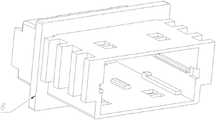
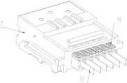
图3图1中接触件模块的结构示意图;Fig. 3 is a schematic structural diagram of the contact module in Fig. 1;
图4是图3中接触件模块的剖视图;Figure 4 is a cross-sectional view of the contact module in Figure 3;
图5是图1中连接器壳的外壳的结构示意图;Fig. 5 is the structural representation of the outer shell of the connector housing in Fig. 1;
图6是图1中连接器壳的内壳的结构示意图;Fig. 6 is the structural representation of the inner shell of the connector shell in Fig. 1;
图7是图1中的连接器的使用状态示意图。FIG. 7 is a schematic diagram of the use state of the connector in FIG. 1 .
图中各附图标记所对应的组成部分的名称为:1-背板,2-子板,3-插头,4-插座,5-连接器壳,6-接触件模块,7-内壳,8-外壳,9-模块容纳腔,10-模块前壳体,11-模块后壳体,12-光纤,13-弹簧,14-环槽,15-环形防尘圈,16-解锁臂,17-插座侧防尘圈,18-防尘罩,19-防尘门。The names of the components corresponding to the reference numbers in the figure are: 1-backplane, 2-sub-board, 3-plug, 4-socket, 5-connector shell, 6-contact module, 7-inner shell, 8- Shell, 9- Module accommodating cavity, 10- Module front housing, 11- Module rear housing, 12- Optical fiber, 13- Spring, 14- Ring groove, 15- Ring dust ring, 16- Unlock arm, 17 - Socket side dust ring, 18- dust cover, 19- dust door.
具体实施方式Detailed ways
下面结合附图对本发明作进一步说明。The present invention will be further described below in conjunction with the accompanying drawings.
本发明中连接器的一个实施例如图1至图7所示,是一种用于背板1与子板2之间互联的光纤连接器,是一种用于固定到子板2上的插头3,插头3用于与固定到背板1上的插座4插接。插头3包括连接器壳5和接触件模块6,连接器壳5包括内壳7和固定在内壳7外侧的外壳8,内壳7上设有供接触件模块6插入的模块容纳腔9,接触件模块6包括供相应的接触件连接的模块壳体,模块壳体包括与插头3前部的插接端对应的模块前壳体10和与插头3后部的光纤12引出端对应的模块后壳体11,模块前壳体10与模块后壳体11之间设置有弹簧13,相应的光纤12穿过模块后壳体11和弹簧13之后连接至模块前壳体10。An embodiment of the connector in the present invention is shown in FIG. 1 to FIG. 7 , which is an optical fiber connector used for interconnection between the
所述模块壳体的外周面上设有环槽14,环槽14内设有用于与连接器壳5上的模块容纳腔9的腔内壁接触以阻挡灰尘的环形防尘圈15,所述环形防尘圈15由套设在模块壳体上的环体形成,环体为柔性胶体,其截面为边缘处设有倒角的矩形,所述环形防尘圈15的各向外周面均为平面,环形防尘圈15装配到所述模块壳体上以后,环形防尘圈15的侧壁与所述环槽14的槽侧壁接触。The outer peripheral surface of the module housing is provided with a
模块后壳体11上设有用于在按压时与连接器壳5解锁的解锁臂16,解锁臂16的前部具有用于在插接到位时与模块容纳腔9的模块插入端的内壁对应的插入端对应部,为了更好地避免灰尘进入连接器壳5内,所述环形防尘圈15设置在所述插入端对应部处。The module
使用时,接触件模块6插入模块容纳腔9时,模块壳体上的环形防尘圈15能够与模块容纳腔9的腔壁接触,从而阻挡灰尘进入连接器壳5内,起到防尘作用,提高防尘性能。In use, when the
为了进一步保证密封效果,插座4的壳体的外周面上还设有用于与插头3的连接器壳5适配的插座侧防尘圈17,插座侧防尘圈17的顶部为M形,插头3与插座4对接时,插座4进入插头3内,与插头3的连接器壳5形成两重防尘部位。另外,插头3的前部还设有防尘罩18,能够在插接时将插座4罩设起来,进一步提高防尘效果。再者,插头3和插座4的插接端均设有防尘门19,进一步提高防尘效果。防尘门19可以采用现有技术中的任意一种防尘门19,具体结构此处不再详细说明。In order to further ensure the sealing effect, the outer peripheral surface of the shell of the
在上述实施例中,所述环形防尘圈15由套设在模块壳体上的环体形成,环体为柔性胶体。在其他实施例中,所述环形防尘圈15也可以是由注塑成型在模块壳体上的环体形成。另外,在其他实施了中,环形防尘圈15也可以不采用柔性胶体,例如采用毛毡制成。In the above embodiment, the
在上述实施例中,环形防尘圈15的截面为边缘处设有倒角的矩形,在其他实施例中,环形防尘圈15的截面也可以为其他形状,例如圆形,并且环形防尘圈15也可以是包括环形主体和设置在环形主体的外周面上的环形翅片的防尘圈。In the above embodiment, the cross-section of the
在上述实施例中,环形防尘圈15设置在接触件模块6的模块壳体上,在其他实施例中,环形防尘圈15也可以设置到模块容纳腔9的腔内壁上。In the above embodiment, the
本发明中连接器的接触件模块的实施例即上述连接器的实施例中所述的设有环形防尘圈15的接触件模块6,具体结构此处不再赘述。The embodiment of the contact piece module of the connector in the present invention is the
当然,在其他实施例中,上述接触件模块也可以用于光纤连接器之外的连接器,例如电信号连接器和用于传输电能的功率电连接器。Of course, in other embodiments, the above-mentioned contact module can also be used for connectors other than optical fiber connectors, such as electrical signal connectors and power electrical connectors for transmitting electrical energy.
最后需要说明的是,以上所述仅为本发明的优选实施例而已,并不用于限制本发明,尽管参照前述实施例对本发明进行了详细的说明,对于本领域的技术人员来说,其依然可以对前述各实施例所记载的技术方案进行不需付出创造性劳动的修改,或者对其中部分技术特征进行等同替换。凡在本发明的精神和原则之内,所作的任何修改、等同替换、改进等,均应包含在本发明的保护范围之内。Finally, it should be noted that the above descriptions are only preferred embodiments of the present invention and are not intended to limit the present invention. Although the present invention has been described in detail with reference to the foregoing embodiments, those skilled in the art will still Modifications may be made to the technical solutions described in the foregoing embodiments without creative efforts, or equivalent replacements may be made to some of the technical features. Any modification, equivalent replacement, improvement, etc. made within the spirit and principle of the present invention shall be included within the protection scope of the present invention.
Claims (10)
Applications Claiming Priority (2)
| Application Number | Priority Date | Filing Date | Title |
|---|---|---|---|
| CN2018107027450 | 2018-06-30 | ||
| CN201810702745 | 2018-06-30 |
Publications (1)
| Publication Number | Publication Date |
|---|---|
| CN110658591Atrue CN110658591A (en) | 2020-01-07 |
Family
ID=69028576
Family Applications (1)
| Application Number | Title | Priority Date | Filing Date |
|---|---|---|---|
| CN201811571020.9APendingCN110658591A (en) | 2018-06-30 | 2018-12-21 | Connector contact module and connector |
Country Status (1)
| Country | Link |
|---|---|
| CN (1) | CN110658591A (en) |
Citations (4)
| Publication number | Priority date | Publication date | Assignee | Title |
|---|---|---|---|---|
| US6715931B1 (en)* | 1999-12-07 | 2004-04-06 | Wenzong Chen | Self-contained fiber optic connector module |
| CN1723404A (en)* | 2003-01-07 | 2006-01-18 | 莫列斯公司 | Fiber Optic Connector Modules with Tail Extenders |
| US20120093466A1 (en)* | 2010-10-19 | 2012-04-19 | Hon Hai Precision Industry Co., Ltd. | Optical connector plug having improved latching mechanism |
| CN104412140A (en)* | 2012-06-12 | 2015-03-11 | 富加宜(亚洲)私人有限公司 | Connector comprising a locking device |
- 2018
- 2018-12-21CNCN201811571020.9Apatent/CN110658591A/enactivePending
Patent Citations (4)
| Publication number | Priority date | Publication date | Assignee | Title |
|---|---|---|---|---|
| US6715931B1 (en)* | 1999-12-07 | 2004-04-06 | Wenzong Chen | Self-contained fiber optic connector module |
| CN1723404A (en)* | 2003-01-07 | 2006-01-18 | 莫列斯公司 | Fiber Optic Connector Modules with Tail Extenders |
| US20120093466A1 (en)* | 2010-10-19 | 2012-04-19 | Hon Hai Precision Industry Co., Ltd. | Optical connector plug having improved latching mechanism |
| CN104412140A (en)* | 2012-06-12 | 2015-03-11 | 富加宜(亚洲)私人有限公司 | Connector comprising a locking device |
Similar Documents
| Publication | Publication Date | Title |
|---|---|---|
| US7467977B1 (en) | Electrical connector with additional mating port | |
| US10114174B2 (en) | Optical connectors and optical coupling systems having a translating element | |
| CN204441556U (en) | Strengthening structure of electrical connector | |
| CN110783758A (en) | An inter-board connector with dust-proof function and its socket | |
| TWM578806U (en) | Fiber optic adapter | |
| CN206804930U (en) | A kind of QSFP28IR optical communications modules housing | |
| CN106483605A (en) | A kind of Socket casing assembly and fiber-optical socket, Optical fiber plug | |
| TWM554650U (en) | Plug electrical connector | |
| CN110596821A (en) | Connectors and Connector Assemblies with Dust Doors | |
| CN105103021A (en) | Optical ports with minimal footprint | |
| CN110600917A (en) | Plug and connector | |
| CN208797292U (en) | connector assembly | |
| TWI492460B (en) | Connector | |
| CN207572646U (en) | connector assembly | |
| CN110658591A (en) | Connector contact module and connector | |
| CN110068899A (en) | The optical fiber connector of multi-directionally plug | |
| CN111244680A (en) | Connector integrated plug and connector integrated assembly | |
| CN106842434A (en) | Fiber optic connector assembly and the joints of optical fibre, joints of optical fibre housing unit | |
| CN110391557B (en) | Connector components | |
| CN216956437U (en) | An LC connector with a dust boot | |
| CN207572565U (en) | Connector Assemblies and Connectors | |
| CN206671616U (en) | Light transmitting-receiving unification module | |
| CN110661129B (en) | Connector with turnover door | |
| CN207572607U (en) | Connector Assemblies and Connectors | |
| CN201133945Y (en) | Optical connector plugs, sockets and optical connectors |
Legal Events
| Date | Code | Title | Description |
|---|---|---|---|
| PB01 | Publication | ||
| PB01 | Publication | ||
| SE01 | Entry into force of request for substantive examination | ||
| SE01 | Entry into force of request for substantive examination | ||
| RJ01 | Rejection of invention patent application after publication | ||
| RJ01 | Rejection of invention patent application after publication | Application publication date:20200107 |