CN110658582A - Display device - Google Patents
Display deviceDownload PDFInfo
- Publication number
- CN110658582A CN110658582ACN201911045059.1ACN201911045059ACN110658582ACN 110658582 ACN110658582 ACN 110658582ACN 201911045059 ACN201911045059 ACN 201911045059ACN 110658582 ACN110658582 ACN 110658582A
- Authority
- CN
- China
- Prior art keywords
- light
- backlight
- light source
- display device
- guide ring
- Prior art date
- Legal status (The legal status is an assumption and is not a legal conclusion. Google has not performed a legal analysis and makes no representation as to the accuracy of the status listed.)
- Pending
Links
Images


Classifications
- G—PHYSICS
- G02—OPTICS
- G02B—OPTICAL ELEMENTS, SYSTEMS OR APPARATUS
- G02B6/00—Light guides; Structural details of arrangements comprising light guides and other optical elements, e.g. couplings
- G02B6/0001—Light guides; Structural details of arrangements comprising light guides and other optical elements, e.g. couplings specially adapted for lighting devices or systems
- G02B6/0011—Light guides; Structural details of arrangements comprising light guides and other optical elements, e.g. couplings specially adapted for lighting devices or systems the light guides being planar or of plate-like form
- G02B6/0033—Means for improving the coupling-out of light from the light guide
- G02B6/005—Means for improving the coupling-out of light from the light guide provided by one optical element, or plurality thereof, placed on the light output side of the light guide
- G02B6/0055—Reflecting element, sheet or layer
- G—PHYSICS
- G02—OPTICS
- G02B—OPTICAL ELEMENTS, SYSTEMS OR APPARATUS
- G02B6/00—Light guides; Structural details of arrangements comprising light guides and other optical elements, e.g. couplings
- G02B6/0001—Light guides; Structural details of arrangements comprising light guides and other optical elements, e.g. couplings specially adapted for lighting devices or systems
- G02B6/0011—Light guides; Structural details of arrangements comprising light guides and other optical elements, e.g. couplings specially adapted for lighting devices or systems the light guides being planar or of plate-like form
- G02B6/0081—Mechanical or electrical aspects of the light guide and light source in the lighting device peculiar to the adaptation to planar light guides, e.g. concerning packaging
- G02B6/0083—Details of electrical connections of light sources to drivers, circuit boards, or the like
Landscapes
- Physics & Mathematics (AREA)
- General Physics & Mathematics (AREA)
- Optics & Photonics (AREA)
- Planar Illumination Modules (AREA)
Abstract
Translated fromChinese
Description
Translated fromChinese技术领域technical field
本申请涉及显示领域,特别涉及一种显示装置。The present application relates to the field of display, and in particular, to a display device.
背景技术Background technique
随着液晶显示技术的发展,特别是全面屏技术的发展,目前多数厂商乃是将显示装置的背光模组设置面朝内的开孔,以供屏下摄像头对应放置,并藉此接收来自外界环境的入射光。With the development of liquid crystal display technology, especially the development of full-screen technology, most manufacturers currently set the backlight module of the display device with an inward-facing opening for the corresponding placement of the camera under the screen, and thereby receive external signals from the outside world. Incident light from the environment.
现有技术的显示装置中,当屏下摄像头对应地设置于所述显示装置所具有的背光模组的开孔下方时,所述开孔将仅仅作为所述屏下摄像头用以接收环境光的收发通道。由于所述开孔的内侧并未设置有任何光源提供亮度,使得所述显示装置在使用时,所述背光模组于所述开孔的区域将处于闲置状态而无法提供任何显示效果。In the display device of the prior art, when the under-screen camera is correspondingly disposed below the opening of the backlight module of the display device, the opening will only be used as a means for the under-screen camera to receive ambient light. Transceiver channel. Since no light source is provided inside the opening to provide brightness, when the display device is in use, the backlight module will be in an idle state in the area of the opening and cannot provide any display effect.
因此,亟需一种显示装置以解决上述技术问题。Therefore, there is an urgent need for a display device to solve the above-mentioned technical problems.
发明内容SUMMARY OF THE INVENTION
本申请提供了一种显示模组,以解决现有显示装置中屏下摄像头区域无法进行显示的技术问题。The present application provides a display module to solve the technical problem that the camera area under the screen cannot be displayed in the existing display device.
为解决上述问题,本申请提供的技术方案如下:In order to solve the above-mentioned problems, the technical solutions provided by this application are as follows:
本申请提出了一种显示装置,其包括显示面板、位于所述显示面板一侧的背光模组,所述背光模组包括:The present application proposes a display device, which includes a display panel and a backlight module located on one side of the display panel, wherein the backlight module includes:
背光单元,开设有背光孔;The backlight unit is provided with a backlight hole;
导光环,设于所述背光孔内侧,所述导光环包括远离所述显示面板设置的入光面和靠近所述显示面板设置的出光面,所述导光环用于将进入所述导光环中的光束导向所述背光孔对应的显示面板区域;A light guide ring is arranged inside the backlight hole, the light guide ring includes a light incident surface disposed away from the display panel and a light exit surface disposed close to the display panel, and the light guide ring is used for entering the light guide ring into the light guide ring. The light beam is directed to the display panel area corresponding to the backlight hole;
光源部件,用于为所述导光环提供光源。The light source component is used for providing a light source for the light guide ring.
在本申请的显示装置中,In the display device of the present application,
所述光源部件包括驱动电路板及位于所述驱动电路板上的至少一光源,所述光源呈阵列式排布于所述驱动电路板上,所述光源围绕所述背光孔的内侧或外侧分布;The light source component includes a driving circuit board and at least one light source located on the driving circuit board, the light sources are arranged in an array on the driving circuit board, and the light sources are distributed around the inner or outer side of the backlight hole ;
所述光源一侧朝向所述导光环的入光面。One side of the light source faces the light incident surface of the light guide ring.
在本申请的显示装置中,In the display device of the present application,
所述出光面所在平面与所述入光面所在平面垂直或呈锐角。The plane where the light-emitting surface is located is perpendicular to the plane where the light-incident surface is located or is at an acute angle.
在本申请的显示装置中,所述导光环还包括一反光面,所述反光面所在平面与所述入光面所在平面垂直或呈一锐角。In the display device of the present application, the light guide ring further includes a reflective surface, and the plane where the reflective surface is located is perpendicular to the plane where the light incident surface is located or forms an acute angle.
在本申请的显示装置中,In the display device of the present application,
所述入光面由处于同一平面的至少一菲涅尔透镜一体形成。The light incident surface is integrally formed by at least one Fresnel lens in the same plane.
在本申请的显示装置中,In the display device of the present application,
所述菲涅尔透镜具有至少一个同心布置的环形齿状结构,以及被所述环形齿状结构环绕的凸透镜结构。The Fresnel lens has at least one concentrically arranged annular tooth structure, and a convex lens structure surrounded by the annular tooth structure.
在本申请的显示装置中,In the display device of the present application,
所述出光面由处于同一平面的至少一微透镜薄膜一体形成;The light emitting surface is integrally formed by at least one microlens film on the same plane;
所述入光面所在的平面与所述微透镜薄膜的焦点所在平面重合;The plane where the light incident surface is located coincides with the plane where the focal point of the microlens film is located;
所述入光面设有至少一透光孔,每一透光孔与每一所述微透镜薄膜对应设置。The light incident surface is provided with at least one light-transmitting hole, and each light-transmitting hole is correspondingly arranged with each of the microlens films.
在本申请的显示装置中,当所述透光孔与所述微透镜薄膜的焦点重合时,所述光源发出的光线经所述微透镜薄膜折射形成垂直于所述入光面的平行光束;In the display device of the present application, when the light-transmitting hole coincides with the focal point of the microlens film, the light emitted by the light source is refracted by the microlens film to form a parallel light beam perpendicular to the light incident surface;
当所述透光孔偏离焦点且处于所述微透镜薄膜的焦平面时,所述光源发出的光线经所述微透镜薄膜折射形成与入射面成一定角度的平行光束。When the light-transmitting hole is deviated from the focal point and is in the focal plane of the microlens film, the light emitted by the light source is refracted by the microlens film to form a parallel light beam at a certain angle with the incident surface.
在本申请的显示装置中,所述导光组件还包括一金属反射层,所述金属反射层设于所述导光环的入光面朝向所述光源一侧;所述透光孔阵列式地排布在所述金属反射层上。In the display device of the present application, the light guide assembly further includes a metal reflection layer, and the metal reflection layer is arranged on the side of the light incident surface of the light guide ring facing the light source; the light transmission holes are arranged in an array. arranged on the metal reflective layer.
在本申请的显示装置中,In the display device of the present application,
所述光源部件还包括一漫反射层,所述漫反射层设于所述驱动电路板上,所述光源暴露在所述漫反射层上。The light source component further includes a diffuse reflection layer, the diffuse reflection layer is arranged on the driving circuit board, and the light source is exposed on the diffuse reflection layer.
在本申请的显示装置中,每一透光孔位于与其对应的每一微透镜薄膜的焦点远离所述导光环中心的一侧。In the display device of the present application, each light-transmitting hole is located on a side where the focal point of each corresponding microlens film is away from the center of the light guide ring.
在本申请的显示装置中,In the display device of the present application,
所述光源包括LED光源或mini LED光源中的一种。The light source includes one of an LED light source or a mini LED light source.
在本申请的显示装置中,所述显示装置还包括位于所述显示模组远离所述显示面板一侧的摄像模组,所述摄像模组与所述背光孔对应;In the display device of the present application, the display device further includes a camera module located on a side of the display module away from the display panel, and the camera module corresponds to the backlight hole;
与所述摄像模组及所述光源部件电连接的控制部件;a control component electrically connected with the camera module and the light source component;
其中,当所述摄像模组中的摄像头开启时,所述控制部件控制所述光源关闭;Wherein, when the camera in the camera module is turned on, the control component controls the light source to turn off;
当所述摄像模组中的摄像头关闭时,所述控制部件控制所述光源开启或关闭。When the camera in the camera module is turned off, the control component controls the light source to be turned on or off.
在本申请的显示装置中,所述背光模组还包括一光线阻隔膜,所述光线阻隔膜设于所述导光环和所述背光单元之间。In the display device of the present application, the backlight module further includes a light blocking film, and the light blocking film is disposed between the light guide ring and the backlight unit.
在本申请的显示装置中,In the display device of the present application,
所述导光环为透明材质或雾面材质制备。The light guide ring is prepared from a transparent material or a matte material.
在本申请的显示装置中,所述背光单元包括位于背板上的反射片、位于所述反射片上的导光板、位于所述导光板上的扩散片、位于所述扩散片上的下增光片、及位于所述下增光片上的上增光片;In the display device of the present application, the backlight unit includes a reflective sheet on the back plate, a light guide plate on the reflective sheet, a diffuser on the light guide plate, a lower light-enhancing sheet on the diffuser, and an upper brightening plate located on the lower brightening plate;
其中,所述背光孔从下至上依次贯穿所述背板、所述反射片、所述导光板、所述扩散片、所述下增光片和所述上增光片。Wherein, the backlight hole penetrates through the back plate, the reflection sheet, the light guide plate, the diffusion sheet, the lower light enhancement sheet and the upper light enhancement sheet in sequence from bottom to top.
在本申请的显示装置中,所述显示面板包括:In the display device of the present application, the display panel includes:
下偏光片,设于所述背光模组上;a lower polarizer, arranged on the backlight module;
阵列基板,设于所述下偏光片上;an array substrate, disposed on the lower polarizer;
彩膜基板,设于所述阵列基板上;以及a color filter substrate disposed on the array substrate; and
上偏光片,设于所述彩膜基板上;an upper polarizer, arranged on the color filter substrate;
其中,所述下偏光片和所述上偏光片在对应所述背光孔位置设有通孔。Wherein, the lower polarizer and the upper polarizer are provided with through holes at positions corresponding to the backlight holes.
有益效果:本申请通过在摄像模组对应的区域设置一背光孔及在所述背光孔内设置一导光环,使得光源部件提供的光源能通过导光环导向所述背光孔对应的显示面板区域。使得当所述摄像模组中摄像头启动时,所述光源关闭,当所述摄像模组中的摄像头不启动时,所述光源开启或关闭,故能够使所述显示面板上的通孔或盲孔重新具有显示能力,且依旧维持摄像模组的影像质量。Beneficial effects: In the present application, a backlight hole is arranged in the area corresponding to the camera module and a light guide ring is arranged in the backlight hole, so that the light source provided by the light source component can be guided to the display panel area corresponding to the backlight hole through the light guide ring. So that when the camera in the camera module is activated, the light source is turned off, and when the camera in the camera module is not activated, the light source is turned on or off, so that the through holes or blinds on the display panel can be enabled. The hole has the display ability again, and still maintains the image quality of the camera module.
附图说明Description of drawings
为了更清楚地说明实施例或现有技术中的技术方案,下面将对实施例或现有技术描述中所需要使用的附图作简单介绍,显而易见地,下面描述中的附图仅仅是发明的一些实施例,对于本领域普通技术人员来讲,在不付出创造性劳动的前提下,还可以根据这些附图获得其他的附图。In order to more clearly illustrate the embodiments or technical solutions in the prior art, the following briefly introduces the accompanying drawings that are used in the description of the embodiments or the prior art. Obviously, the drawings in the following description are only for invention. In some embodiments, for those of ordinary skill in the art, other drawings can also be obtained according to these drawings without any creative effort.
图1为本申请显示装置的第一种结构图;1 is a first structural diagram of a display device of the application;
图2为本申请显示装置的第二种结构图;2 is a second structural diagram of the display device of the application;
图3为本申请显示装置的第三种结构图;3 is a third structural diagram of the display device of the application;
图4为本发明显示装置中背光模组的第一种结构示意图;4 is a first structural schematic diagram of a backlight module in a display device of the present invention;
图5为本发明显示装置中光源部件的第一种结构示意图;5 is a first structural schematic diagram of a light source component in a display device of the present invention;
图6为本发明显示装置中导光环及光源的结构示意图;6 is a schematic structural diagram of a light guide ring and a light source in a display device of the present invention;
图7为本发明显示装置中导光环的第一种仰视图;7 is a first bottom view of the light guide ring in the display device of the present invention;
图8为本发明显示装置中背光模组的第二种结构示意图;8 is a schematic diagram of a second structure of the backlight module in the display device of the present invention;
图9为本发明显示装置中微透镜薄膜的光路原理示意图;9 is a schematic diagram of the optical path principle of the microlens film in the display device of the present invention;
图10为本发明显示装置中光源部件的第一种结构示意图;10 is a first structural schematic diagram of the light source component in the display device of the present invention;
图11为本发明显示装置中光源部件的第二种结构示意图;11 is a schematic diagram of the second structure of the light source component in the display device of the present invention;
图12为本发明显示装置中背光模组的第二种结构示意图;12 is a schematic diagram of the second structure of the backlight module in the display device of the present invention;
图13为本申请显示装置的第四种结构图。FIG. 13 is a fourth structural diagram of the display device of the present application.
具体实施方式Detailed ways
以下各实施例的说明是参考附加的图示,用以例示本申请可用以实施的特定实施例。本申请所提到的方向用语,例如[上]、[下]、[前]、[后]、[左]、[右]、[内]、[外]、[侧面]等,仅是参考附加图式的方向。因此,使用的方向用语是用以说明及理解本申请,而非用以限制本申请。在图中,结构相似的单元是用以相同标号表示。The following descriptions of the various embodiments refer to the accompanying drawings to illustrate specific embodiments in which the present application may be practiced. Directional terms mentioned in this application, such as [upper], [lower], [front], [rear], [left], [right], [inner], [outer], [side], etc., are only for reference Additional schema orientation. Therefore, the directional terms used are used to describe and understand the present application, rather than to limit the present application. In the figures, structurally similar elements are denoted by the same reference numerals.
在现有技术的显示装置中,当屏下摄像头对应地设置于所述显示装置所具有的背光模组的开孔下方时,所述开孔将仅仅作为所述屏下摄像头用以接收环境光的收发通道。由于所述开孔的内侧并未设置有任何光源提供亮度,使得所述显示装置在使用时,所述背光模组于所述开孔的区域将处于闲置状态而无法提供任何显示效果。本申请基于上述技术问题提出了一种显示装置。In the display device of the prior art, when the under-screen camera is correspondingly disposed under the opening of the backlight module of the display device, the opening will only serve as the under-screen camera to receive ambient light the transceiver channel. Since no light source is provided inside the opening to provide brightness, when the display device is in use, the backlight module will be in an idle state in the area of the opening and cannot provide any display effect. The present application proposes a display device based on the above technical problems.
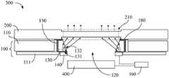
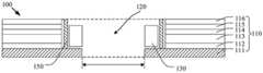
请参阅图1,所述显示装置300包括显示面板200、位于所述显示面板200一侧的背光模组100所述背光模组100包括:Referring to FIG. 1 , the
背光单元110,开设有背光孔120。在本实施例中,所述背光孔120可以为圆形孔。The
导光环130,设于所述背光孔120内侧,所述导光环130包括远离所述显示面板200设置的入光面131和靠近所述显示面板200设置的出光面132,所述导光环130用于将进入所述导光环130中的光束导向所述背光孔120对应的显示面板区域210。所述导光环130的形状及尺寸与所述背光孔120的形状及尺寸相适配。The
光源部件140,用于为所述导光环130提供光源。所述光源部件140的形状及尺寸与所述导光环130的形状及尺寸相适配。The
在本实施例中,所述光源部件140包括驱动电路板141及位于所述驱动电路板141上的至少一光源142,所述光源142呈阵列式排布于所述驱动电路板141上,所述光源围绕所述背光孔的内侧或外侧分布。所述光源142一侧朝向所述导光环130的入光面131。In this embodiment, the
在本实施例中,所述显示装置300还可以包括位于所述背光模组100一侧且远离所述显示面板200的摄像模组400,所述摄像模组400与所述背光孔120对应。所述摄像模组400在所述背光单元110上的正投影位于所述背光孔120内。In this embodiment, the
在本实施例中,所述显示装置300是否设置有所述摄像模组400,本申请不作具体限制。In this embodiment, whether the
本申请提出了一种显示装置300,包括显示面板200、背光模组100及摄像模组400。所述背光模组100包括背光单元110,开设有背光孔120,所述摄像模组400与所述背光孔120对应;导光环130,设于所述背光孔120内侧,所述导光环130包括入光面131和出光面132,所述导光环130用于将进入所述导光环130中的光束导向所述背光孔120对应的显示面板区域210;光源部件140,用于为所述导光环130提供光源。本申请通过在摄像模组400对应的区域设置一背光孔120及在所述背光孔120内设置一导光环130,使得光源部件140提供的光源能通过导光环130导向所述背光孔120对应的显示面板区域210。使得当所述摄像模组400中摄像头启动时,所述光源142关闭,当所述摄像模组400中的摄像头不启动时,所述光源142开启或关闭,故能够使所述显示面板200上的通孔或盲孔重新具有显示能力,且依旧维持摄像模组400的影像质量。The present application proposes a
下面结合具体实施例对本申请的技术方案进行说明。The technical solutions of the present application will be described below with reference to specific embodiments.
实施例一Example 1
请参阅图1~3,所述出光面132所在平面与所述入光面131所在平面呈锐角。Referring to FIGS. 1-3 , the plane where the
请参阅图1,所述出光面132与所述入光面131的夹角为锐角。在实际应用中,所述出光面132与所述入光面131之间的夹角可以为10度、20度、30度、45度、50度、60度、70度、80度等,用来保障从所述入光面131进入的光束。Referring to FIG. 1 , the included angle between the light-emitting
在从所述出光面132射出时,向所述背光孔120对应的所述显示面板区域210投射,以补偿所述摄像模组400对应的所述显示面板区域210额外光源,使得显示面板200的这部分区域能够正常显示,且不影响所述摄像模组400的正常工作。When emitting from the
在本实施例中,所述背光模组100还包括一光线阻隔膜150。所述光线阻隔膜150设于所述导光环130和所述背光单元110之间。所述光线阻隔膜150用于阻隔背光模组100的光线,以及防止在摄像模组400进行摄像时受到所述背光模组100的光源142所发出的光的影响。In this embodiment, the
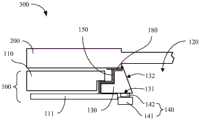
在图1的基础上,所述显示装置300所具有的所述导光环130更进一步依据不同的背光单元110的设计,相应的变化为如图2或图3所示例的剖面结构,以同样可透过所述导光环130的所述出光面132的设置,引导所述光源部件140所发射的光束朝对应于所述背光孔120处的所述显示面板区域210发射,藉此为对应于所述背光孔120处的所述显示面板区域210提供适当的亮度。On the basis of FIG. 1 , the
在本实施例中,当所述导光环130设置为图3或图4所具有的剖面结构时,所述导光环130与所述背光单元110的交界处所设置的所述光线阻隔膜150亦将相应地变更其形状,以有效阻隔所述背光单元110内部的光线漏出至所述背光孔120的中心区域,从而避免影响到所述摄像模组400的摄像质量。In this embodiment, when the
在本实施例中,所述光源142可以包括LED光源或mini LED光源中的一种。下述实施例中的光源部件140可以与本实施例相同。In this embodiment, the
在本实施例中,所述导光环130可以为透明材质或雾面材质制备。透明的导光环130可以有效地引导光源部件140所射出的光束通过所述出光面132朝向对应于所述背光孔120处的所述显示面板区域210发射,降低光源部件140的光损现象。下述实施例中的导光环130材料可以与本实施例相同。In this embodiment, the
请参阅图1,所述显示装置300还包括控制部件160。Referring to FIG. 1 , the
所述控制部件160分别与所述摄像模组400和所述光源部件140电连接。所述控制部件160用于当所述摄像模组400启动时,使所述光源部件140关闭,使所述摄像模组400可不受干扰地获取外界影像数据。当所述摄像模组400关闭时,则可依据显示面板200的实际显示情况控制所述光源部件140开启或关闭。The
在本实施例中,当所述摄像模组400启动时,所述光源部件140将关闭,以使得所述摄像模组400可不受影响地接收来来自外界的环境光源进行感光。当所述摄像模组400不启动时,所述光源部件140则能够依据显示面板200的实际显示情况,使其处于开启状态并朝所述显示面板200的显示面板区域210发射光束以提供亮度。In this embodiment, when the
或者,所述摄像模组400能够在不显示时使所述光源部件140处于关闭状态而不朝向所述显示面板200的所述显示面板区域210发射光束,使对应于所述背光孔120的所述显示面板区域210处于全黑状态,故能使现有技术中处于闲置状态而无法提供任何显示效果的显示面板200得以重新具有显示能力,且依旧维持所述屏下摄像头所能获取的影像质量,提升终端产品(即:采用全面屏技术的显示面板200)的应用场景和使用体验,从而具有竞争力。Alternatively, the
本实施例通过在摄像模组400对应的区域设置一背光孔120及在所述背光孔120内设置一导光环130,使得光源部件140提供的光源能通过导光环130导向所述背光孔120对应的显示面板区域210。使得当所述摄像模组400中摄像头启动时,所述光源142关闭,当所述摄像模组400中的摄像头不启动时,所述光源142开启或关闭,故能够使所述显示面板200上的通孔或盲孔重新具有显示能力,且依旧维持摄像模组400的影像质量。In this embodiment, a
实施例二Embodiment 2
本实施例与实施例一相同或相似,不同之处在于:This embodiment is the same or similar to the first embodiment, the difference is:
在图1~3的基础上,所述出光面132的表面可进一步具有微结构,使自所述出光面132射出的光线可因微结构的设置而尽量均匀的分布在所述背光孔120内侧,从而使对应于所述背光孔120处的所述显示面板区域210具有均匀的亮度。On the basis of FIGS. 1 to 3 , the surface of the light-emitting
请参阅图4~6,所述出光面132所在平面与所述入光面131所在平面垂直或呈一锐角。Referring to FIGS. 4-6 , the plane where the light-emitting
在本实施例中,当所述出光面132所在的平面与所述入光面131所在的平面呈一锐角时,便于光线从所述出光面132折射进入所述背光孔120内时朝向上方,即背光孔120的孔口方向传播。In this embodiment, when the plane where the
在本实施例中,所述背光孔120用于容置摄像模组400、或者所述背光孔120与摄像模组400的镜头位置对应设置。In this embodiment, the
在本实施例中,所述显示装置300同样包括与实施例一相同的控制部件(未画出)。所述控制部件可以根据实际情况控制所述光源部件140以及所述摄像模组400。In this embodiment, the
当所述摄像模组400中摄像头开启时,所述光源部件140处于非工作状态,所述背光孔120作为所述摄像模组400接收环境光的通道。当所述摄像模组400中摄像头关闭时,所述光源部件140处于工作状态,所述光源部件140中的光源142发出的光线穿过所述导光环130为所述背光孔120提供光。When the camera in the
在本实施例中,所述导光环130具有对光线全反射和折射的作用,便于光线尽可能地向所述背光孔120的区域传播。本实施例通过在所述背光孔120内侧设置导光环130以及光源部件140,从而在所述背光孔120内侧提供了光源,解决了在摄像头关闭时在所述背光孔120对应位置的颜色较暗的问题。In this embodiment, the
本实施例中,所述背光模组100还包括一光线阻隔膜150,所述光线阻隔膜150设于所述导光环130和所述背光单元110之间。设置所述光线阻隔膜150的目的是为了阻隔背光模组100的光线,防止在摄像头进行摄像时受到所述背光模组100的光源部件140所发出的光的影响。In this embodiment, the
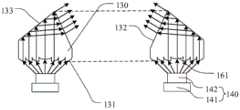
请参阅图5~6,在所述导光环130靠近所述光线阻隔膜150一侧还包括一反光面133。所述反光面133所在的平面与所述入光面131所在的平面一垂直或呈一锐角。Referring to FIGS. 5-6 , the
在本实施例中,所述光源142的光线(图5、图6中箭头表示光线传播方向)从所述入光面131进入所述导光环130内,经所述反光面133反射使得光线从所述出光面132射出进入所述背光孔120内,从而给所述背光孔120提供光。所述反光面133所在平面与所述入光面131所在平面呈一锐角,更便于所述光源142的光线从所述入光面131进入所述导光环130内后经反射进入所述背光孔120。In this embodiment, the light of the light source 142 (the arrow in FIG. 5 and FIG. 6 indicates the light propagation direction) enters the
请参阅图4,所述导光环130包括所述入光面131及所述出光面132而不包括所述反光面133,所述出光面132所在平面与所述入光面131所在平面呈一锐角。Please refer to FIG. 4 , the
请参阅图5,所述出光面132所在平面与所述入光面131所在平面垂直,所述反光面133所在平面与所述入光面131所在平面呈一锐角。Referring to FIG. 5 , the plane where the light-emitting
请参阅图6,所述出光面132所在平面与所述入光面131所在平面呈一锐角,且所述反光面133所在平面与所述入光面131所在平面也呈一锐角。Referring to FIG. 6 , the plane where the light-emitting
本申请的具体实施例不限于上述几种导光环130结构,只要满足所述光源142发射的光线经所述导光环130传播进入所述背光孔120内,其均属于本发明保护范围。The specific embodiments of the present application are not limited to the above-mentioned structures of the
在本实施例中,所述导光环130的材质可以是塑料,也可以是光学级的玻璃,其材质优选具有一定折射率,使光线尽可能地向所述背光孔120区域传播。In this embodiment, the material of the
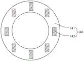
请参阅图7,所述入光面131可以由处于同一平面若干菲涅尔透镜160一体形成。即多个所述菲涅尔透镜160呈环形分布于所述入光面131。Referring to FIG. 7 , the
在本实施例中,所述光源142与所述菲涅尔透镜160一一对应设置。所述光源142与所述菲涅尔透镜160的数量相等。In this embodiment, the
在本实施例中,所述光源142位于所述菲涅尔透镜160的焦点位置。任一所述光源142发出的光均可经过与之对应的菲涅尔透镜160后形成平行光,具体请参阅图5~6。In this embodiment, the
请参阅图7,所述菲涅尔透镜160具有若干个同心布置的环形齿状结构161,以及被所述环形齿状结构161环绕的凸透镜结构。所述菲涅尔透镜160又名螺纹透镜,由聚烯烃材料注压而成的薄片或由玻璃制作。所述菲涅尔透镜160的一面为平面,另一面刻录了由小到大的同心圆,并尽可能多的去掉光学材料以减薄厚度,而保留表面的弯曲度,即形成所述同心布置的环形齿状结构161。Referring to FIG. 7 , the
请参阅图5~6,所述光源142位于所述菲涅尔透镜160焦点位置发出光线,从所述环形齿状结构161一侧入射,经过所述菲涅尔透镜160后以平行光方式射出,因此本实施例的所述菲涅尔透镜160等效于普通菲涅尔透镜160减薄后的效果。Please refer to FIGS. 5 to 6 , the
在本实施例中,所述驱动电路板141的形状及尺寸与所述导光环130的形状及尺寸相适配,即呈环形设置。In this embodiment, the shape and size of the driving
在本实施例中,所述光源142可以呈阵列式分布于所述驱动电路板141上。In this embodiment, the
由于所述光源142的光型较发散,为了能更好地实现导光功能以及尽可能利用光效,所述导光环130的入光面131可以包括多个所述菲涅尔透镜160。所述光源142可以位于所述菲涅尔透镜160的焦点位置,以实现所述光源大角度的光线准直作用,避免了发散光造成所述背光模组100的漏光问题。Since the light type of the
请参阅图4,所述导光环130的所述入光面131卡设于所述背板111上,所述光源142与所述背板111的上表面处于同一平面内。这样更利于所述导光环130固定在所述背光孔120内侧。当然,在其他实施例中,所述光源142和所述入光面131也可设置在所述导光环130的其他位置,其变形均属于本发明保护范围。Referring to FIG. 4 , the
本实施例提供的所述显示装置300通过在所述背光孔120内侧设置所述导光环130以及所述光源部件140,解决了所述背光孔120内侧无光源提供亮度的问题,以及解决了所述显示装置300在摄像头关闭进入显示状态时在所述背光孔120对应位置的颜色较暗的技术问题。In the
实施例三Embodiment 3
本实施例与实施例二相同或相似,不同之处在于:This embodiment is the same as or similar to the second embodiment, the difference is:
请参阅图8~12,所述出光面132由处于同一平面的若干微透镜薄膜170一体形成。Referring to FIGS. 8-12 , the
在本实施例中,所述微透镜薄膜170呈环形分布于所述出光面132。所述入光面131所在的平面与所述微透镜薄膜170的焦点O所在平面重合。所述入光面131设有多个透光孔171,每一透光孔171与每一微透镜薄膜170相对应设置,这样便于所述光源142发射出的光线经所述入光面131进入并从所述出光面132的所述微透镜薄膜170进行折射射出,从而能够得到最终射出的平行光束。In this embodiment, the
在本实施例中,所述光源部件140的设置可以与实施例二相同。所述驱动电路板141可以为柔性电路板,其是以聚酰亚胺或聚酯薄膜为基材制成,具有配线密度高、重量轻、厚度薄的特点。In this embodiment, the arrangement of the
在本实施例中,所述透光孔171可以位于所述微透镜薄膜170的焦点O所在的平面。即所述透光孔171处于所述微透镜薄膜170的焦平面,大部分光线经微透镜薄膜170后主光线方向变得有指向性,该方向与所述透光孔171和所述微透镜薄膜170的焦点O的位置有关。In this embodiment, the light-transmitting
在本实施例中,当所述透光孔171与所述微透镜薄膜170的焦点O重合时,则所述光源142发射出的光线(图8、图9中用箭头表示)经所述微透镜薄膜170折射形成垂直于所述入光面131的平行光束。当所述透光孔171偏离焦点O且处于所述微透镜薄膜170的焦平面时,所述光源142发出的光线经所述微透镜薄膜170折射形成与入射面成一定角度的平行光束。In this embodiment, when the light-transmitting
因此,本实施例可以通过调整所述透光孔171相对于所述微透镜薄膜170的焦点O的位置,以控制入射光的出光方向,实现了将所述光源142发出的光导向某一方向。Therefore, in this embodiment, by adjusting the position of the light-transmitting
请参阅图8,所述背光模组100还包括一金属层反射层172。所述金属层反射层172设于所述导光环130的入光面131朝向所述光源142的一侧。所述金属层反射层172上阵列排布有多个透光孔171。Please refer to FIG. 8 , the
在本实施例中,所述入光面131所在的平面与所述微透镜薄膜170的焦点O所在平面重合,从而使所述金属层反射层172所在的平面与所述微透镜薄膜170的焦点O所在的平面重合,即所述透光孔171位于所述微透镜薄膜170的焦点O所在平面内。In this embodiment, the plane where the
在本实施例中,设置所述透光孔171使得其透过所述光源142发射出的光线可近似当作点光源。In this embodiment, the light-transmitting
请参阅图8,所述光源部件140还包括一漫反射层143。所述漫反射层143设于所述驱动电路板141上,所述光源142暴露在所述漫反射层143上。Referring to FIG. 8 , the
在本实施例中,所述漫反射层143用于反射未通过所述透光孔171的光线,同时所述漫反射层143与所述金属层反射层172相平行设置。未通过所述透光孔171的光线经所述金属层反射层172反射再经所述漫反射层143漫反射,这样在所述金属层反射层172和所述漫反射层143之间充满了方向随机的光线,从而达到多次利用所述光源142发射的光线。本发明重复利用多次反射的光线,减小了光效损失,达到了节能效果。In this embodiment, the diffuse
在本实施例中,所述漫反射层143的材质可以包括白色油墨,其反光效果良好且不易吸收光线。In this embodiment, the material of the diffuse
在本实施例中,每一透光孔171均位于与其对应的每一微透镜薄膜170的焦点O远离所述导光环130中心的一侧。相邻两个所述透光孔171的中心与相邻两个所述微透镜薄膜170的焦点O的间距相等。这样所述透光孔171均偏离所述微透镜薄膜170的焦点O,则所述光源142发射出的光线经所述微透镜薄膜170折射形成与入射面成一定角度的平行光束,且该平行光束均被导向所述导光环130中心的一侧。In this embodiment, each light-transmitting
请参阅图10~11,所述光源142呈阵列式排布于所述驱动电路板141上。所述光源142的一侧为发光侧。所述光源142呈阵列式排布的方式有多种形式。Referring to FIGS. 10 to 11 , the
请参阅图10,所述光源142的排布方向一致。Referring to FIG. 10 , the
请参阅图图11,所述光源142的排布方向的交点为所述驱动电路板141的中心点。Referring to FIG. 11 , the intersection of the arrangement directions of the
在本实施例中,所述透光孔171位于所述微透镜薄膜170的焦点O所在平面内,透光孔171并未与焦点O重合且远离所述背光孔120的一侧。这样所述光源142发射出的光线经所述透光孔171进入所述微透镜薄膜170内进行折射射出,从而能够形成朝向所述背光孔120的平行光束。In this embodiment, the light-transmitting
本实施例中,所述背光模组100的形状及尺寸与所述背光孔120的形状及尺寸相适配。所述背光孔120优选为圆形孔。In this embodiment, the shape and size of the
本实施例中,所述导光环130、所述光源142均呈环形,优选为圆环形,即与所述背光孔120优选为圆形孔时相适配。In this embodiment, the
请参阅图12所示,所述背光模组100还包括一光线阻隔膜150,所述光线阻隔膜150设于所述背光模组100和所述背光单元110之间。设置所述光线阻隔膜150的目的是为了阻隔所述背光模组100的光线,防止在摄像头进行摄像时受到所述背光模组100的光源142的影响。Referring to FIG. 12 , the
本实施例提供的所述显示装置300通过在所述背光孔120内侧设置所述导光环130以及所述光源142,解决了所述背光孔120内侧无光源提供亮度的问题,以及解决了所述显示装置300在摄像头关闭进行显示状态时在所述背光孔120对应位置的亮度偏暗的技术问题。In the
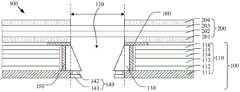
在上述实施例中,所述显示装置300还可以包括位于所述背光模组100与所述显示面板200之间的遮光胶180。In the above embodiment, the
本申请以实施例二为例进行说明,请参阅图13。The present application takes Embodiment 2 as an example for description, please refer to FIG. 13 .
所述遮光胶180的下表面部分贴附于所述导光环130的上表面,另一部分贴附于所述上增光片116的上表面(即所述背光模组100的上表面)。Part of the lower surface of the light-shielding
所述遮光胶180的上表面则贴附于所述显示面板200的下表面,从而所述遮光胶180将所述背光模组100和所述显示面板200粘附结合在一起。所述遮光胶180起到连接所述背光模组100和所述显示面板200的作用,并且可以防止从所述背光孔120位置漏光,因此所述遮光胶180的形状及尺寸与所述背光孔120的形状及尺寸相适配,即所述遮光胶180呈环形环绕所述背光孔120,也就是说在对应所述背光孔120的位置不设置所述遮光胶180。The upper surface of the light-shielding
在上述实施例中,所述背光单元110可以包括从下至上依次层叠设置的反射片112、导光板113、扩散片114、下增光片115和上增光片116。In the above embodiment, the
所述反射片112设于所述背板111上;所述导光板113设于所述反射片112上;所述扩散片114设于所述导光板113上;所述下增光片115设于所述扩散片114上;所述上增光片116设于所述下增光片115上。The
所述背光孔120从下至上依次贯穿所述背板111、所述反射片112、所述导光板113、所述扩散片114、所述下增光片115和所述上增光片116。The
所述扩散片114对光线扩散以提供一个均匀的面光源。所述下增光片115和所述上增光片116可增强光源的亮度。所述背光单元110的发光效果将直接影响到所述背光模组100的视觉效果。The
在上述实施例中,所述显示面板200包括下偏光片201、阵列基板202、彩膜基板203和上偏光片204,具体请参阅图13。In the above embodiment, the
在本实施例中,所述下偏光片201,设于所述背光模组100上;所述阵列基板202设于所述下偏光片201上;所述彩膜基板203设于所述阵列基板202上;所述上偏光片204设于所述彩膜基板203上;其中所述下偏光片201和所述上偏光片204在对应所述背光孔120位置设有通孔,所述通孔能够提高所述显示面板200的透光率。所述遮光胶180的上表面贴附于所述下偏光片201的下表面将所述背光模组100和所述显示面板200粘附结合在一起。In this embodiment, the
所述显示装置300可装设于具有通孔(如:挖孔、水滴、凹口、及面外等)或具有盲孔的所述显示面板200,从而消弭当所述显示面板200具有通孔或盲孔时,所述通孔区域或所述盲孔区域无法用于显示的问题,且所述背光单元110可使用背板111或反射膜作为背面,以均匀或有效利用所述背光单元110所发射的光。The
综上所述,藉由本揭示的所述导光环130与所述光源部件140的设置,使得所述显示装置300所具有的所述背光模组100可于所述背光孔120的区域提供光线与亮度控制,使现有技术中处于闲置状态而无法提供任何显示效果的显示面板200上的通孔或盲孔得以重新具有显示能力,且依旧维持所述摄像模组400所能获取的影像质量,进而提升终端产品的应用场景和使用体验,从而具有竞争力。To sum up, with the arrangement of the
本实施例中的所述显示装置可以为手机、平板电脑、电视机、显示器、笔记本电脑、数码相框、导航仪等任何具有显示功能的产品或部件。The display device in this embodiment may be any product or component with a display function, such as a mobile phone, a tablet computer, a television, a monitor, a notebook computer, a digital photo frame, and a navigator.
本申请提出了一种显示装置,包括显示面板及背光模组。该背光模组包括背光单元,开设有背光孔;导光环,设于该背光孔内侧,该导光环包括入光面和出光面,该导光环用于将进入该导光环中的光束导向该背光孔对应的显示面板区域;光源部件,用于为该导光环提供光源。本申请通过在摄像模组对应的区域设置一背光孔及在所述背光孔内设置一导光环,使得光源部件提供的光源能通过导光环导向所述背光孔对应的显示面板区域。使得当所述摄像模组中摄像头启动时,所述光源关闭,当所述摄像模组中的摄像头不启动时,所述光源开启或关闭,故能够使所述显示面板上的通孔或盲孔重新具有显示能力,且依旧维持摄像模组的影像质量。The present application proposes a display device including a display panel and a backlight module. The backlight module includes a backlight unit with a backlight hole; a light guide ring is arranged inside the backlight hole, the light guide ring includes a light incident surface and a light exit surface, and the light guide ring is used to guide the light beam entering the light guide ring to the backlight The display panel area corresponding to the hole; the light source component is used to provide the light source for the light guide ring. In the present application, a backlight hole is arranged in the area corresponding to the camera module and a light guide ring is arranged in the backlight hole, so that the light source provided by the light source component can be guided to the display panel area corresponding to the backlight hole through the light guide ring. So that when the camera in the camera module is activated, the light source is turned off, and when the camera in the camera module is not activated, the light source is turned on or off, so that the through holes or blinds on the display panel can be enabled. The hole has the display ability again, and still maintains the image quality of the camera module.
综上所述,虽然本申请已以优选实施例揭露如上,但上述优选实施例并非用以限制本申请,本领域的普通技术人员,在不脱离本申请的精神和范围内,均可作各种更动与润饰,因此本申请的保护范围以权利要求界定的范围为准。To sum up, although the present application has disclosed the above-mentioned preferred embodiments, the above-mentioned preferred embodiments are not intended to limit the present application. Those of ordinary skill in the art, without departing from the spirit and scope of this application, can Therefore, the scope of protection of the present application is subject to the scope defined by the claims.
Claims (17)
Translated fromChinesePriority Applications (2)
| Application Number | Priority Date | Filing Date | Title |
|---|---|---|---|
| US16/769,618US11300828B2 (en) | 2019-05-10 | 2020-03-04 | Display device |
| PCT/CN2020/077700WO2020228395A1 (en) | 2019-05-10 | 2020-03-04 | Display device |
Applications Claiming Priority (6)
| Application Number | Priority Date | Filing Date | Title |
|---|---|---|---|
| CN201910387457.5ACN110161749A (en) | 2019-05-10 | 2019-05-10 | Applied to the panel device for shielding lower camera |
| CN2019103874575 | 2019-05-10 | ||
| CN2019106867978 | 2019-07-29 | ||
| CN201910686797.8ACN110491290A (en) | 2019-07-29 | 2019-07-29 | Backlight module and display device |
| CN201910693204.0ACN110456444A (en) | 2019-07-30 | 2019-07-30 | Leaded light component, backlight module and display device |
| CN2019106932040 | 2019-07-30 |
Publications (1)
| Publication Number | Publication Date |
|---|---|
| CN110658582Atrue CN110658582A (en) | 2020-01-07 |
Family
ID=69042296
Family Applications (2)
| Application Number | Title | Priority Date | Filing Date |
|---|---|---|---|
| CN201911045059.1APendingCN110658582A (en) | 2019-05-10 | 2019-10-30 | Display device |
| CN201921855432.5UActiveCN210894768U (en) | 2019-05-10 | 2019-10-30 | Display device |
Family Applications After (1)
| Application Number | Title | Priority Date | Filing Date |
|---|---|---|---|
| CN201921855432.5UActiveCN210894768U (en) | 2019-05-10 | 2019-10-30 | Display device |
Country Status (1)
| Country | Link |
|---|---|
| CN (2) | CN110658582A (en) |
Cited By (17)
| Publication number | Priority date | Publication date | Assignee | Title |
|---|---|---|---|---|
| CN111510615A (en)* | 2020-05-29 | 2020-08-07 | 昆山丘钛光电科技有限公司 | A camera module and electronic equipment |
| CN111624806A (en)* | 2020-05-29 | 2020-09-04 | 厦门天马微电子有限公司 | Display module and display device |
| CN111752039A (en)* | 2020-07-03 | 2020-10-09 | 西人马(厦门)科技有限公司 | Liquid crystal display module and display device |
| CN111787137A (en)* | 2020-05-28 | 2020-10-16 | 厦门天马微电子有限公司 | Display device |
| CN111948852A (en)* | 2020-08-14 | 2020-11-17 | 武汉华星光电技术有限公司 | Backlight module and display device |
| CN112015003A (en)* | 2020-09-02 | 2020-12-01 | 武汉华星光电技术有限公司 | Display device |
| CN112130377A (en)* | 2020-10-10 | 2020-12-25 | 厦门天马微电子有限公司 | Display device and control method thereof |
| CN112698529A (en)* | 2020-12-28 | 2021-04-23 | 武汉华星光电技术有限公司 | Liquid crystal display device having a plurality of pixel electrodes |
| CN113126365A (en)* | 2020-01-15 | 2021-07-16 | RealMe重庆移动通信有限公司 | Electronic equipment and liquid crystal display assembly thereof |
| CN113744641A (en)* | 2021-08-19 | 2021-12-03 | 惠州华星光电显示有限公司 | Display device |
| CN113810564A (en)* | 2020-06-16 | 2021-12-17 | 中兴通讯股份有限公司 | Camera control method and device and under-screen camera structure |
| CN114089557A (en)* | 2021-11-29 | 2022-02-25 | 武汉华星光电技术有限公司 | Display device |
| CN114945860A (en)* | 2020-01-27 | 2022-08-26 | 株式会社日本显示器 | Electronic equipment |
| CN115032833A (en)* | 2022-05-26 | 2022-09-09 | 武汉华星光电技术有限公司 | Display device |
| TWI784542B (en)* | 2021-05-25 | 2022-11-21 | 啓碁科技股份有限公司 | Electronic device with light indication function |
| WO2022257622A1 (en)* | 2021-06-11 | 2022-12-15 | 中兴通讯股份有限公司 | Under-screen photographing display apparatus and control method therefor, controller, and terminal device |
| CN115793324A (en)* | 2022-12-09 | 2023-03-14 | 厦门天马微电子有限公司 | Display module and display device |
Families Citing this family (6)
| Publication number | Priority date | Publication date | Assignee | Title |
|---|---|---|---|---|
| CN110658582A (en)* | 2019-05-10 | 2020-01-07 | 武汉华星光电技术有限公司 | Display device |
| CN111752043A (en)* | 2020-07-10 | 2020-10-09 | 武汉华星光电技术有限公司 | Backlight module and display device |
| EP4180867A4 (en) | 2020-07-10 | 2024-08-28 | Wuhan China Star Optoelectronics Technology Co., Ltd. | Backlight module and display apparatus |
| CN114125086A (en)* | 2020-08-27 | 2022-03-01 | 北京小米移动软件有限公司 | Display device, display method, and electronic device |
| CN113889053B (en)* | 2021-06-04 | 2022-07-22 | 荣耀终端有限公司 | Screen brightness adjustment method based on ambient light sensor |
| CN113777832B (en)* | 2021-09-17 | 2022-07-12 | 武汉华星光电技术有限公司 | Display panel and electronic device |
Citations (13)
| Publication number | Priority date | Publication date | Assignee | Title |
|---|---|---|---|---|
| US20010015780A1 (en)* | 2000-02-14 | 2001-08-23 | Akira Yamaguchi | Light diffusing plate, liquid crystal display apparatus and rear projection apparatus |
| US20060203485A1 (en)* | 2005-03-11 | 2006-09-14 | Coretronic Corporation | Backlight button assemblage |
| JP2008281648A (en)* | 2007-05-08 | 2008-11-20 | Citizen Electronics Co Ltd | Optical member, backlight unit and display device |
| KR20090126531A (en)* | 2008-06-04 | 2009-12-09 | 삼성전자주식회사 | An optical film, a backlight unit having the optical film, and an LCD device having the backlight unit |
| CN102287690A (en)* | 2011-04-29 | 2011-12-21 | 友达光电股份有限公司 | Backlight module |
| JP4973794B1 (en)* | 2011-04-06 | 2012-07-11 | ソニー株式会社 | Display device |
| CN104900683A (en)* | 2015-06-10 | 2015-09-09 | 京东方科技集团股份有限公司 | Display substrate, preparing method and display device thereof |
| CN107784989A (en)* | 2017-10-27 | 2018-03-09 | 信利光电股份有限公司 | A kind of liquid crystal display device with camera module |
| CN108681131A (en)* | 2018-07-27 | 2018-10-19 | 厦门天马微电子有限公司 | Display device |
| CN208027665U (en)* | 2018-04-28 | 2018-10-30 | 京东方科技集团股份有限公司 | display device |
| CN208123912U (en)* | 2018-03-07 | 2018-11-20 | 深圳市玲涛光电科技有限公司 | A kind of light source assembly and its display device |
| CN109541849A (en)* | 2019-01-04 | 2019-03-29 | 京东方科技集团股份有限公司 | Backlight module and driving method, display panel |
| CN210894768U (en)* | 2019-05-10 | 2020-06-30 | 武汉华星光电技术有限公司 | Display device |
- 2019
- 2019-10-30CNCN201911045059.1Apatent/CN110658582A/enactivePending
- 2019-10-30CNCN201921855432.5Upatent/CN210894768U/enactiveActive
Patent Citations (13)
| Publication number | Priority date | Publication date | Assignee | Title |
|---|---|---|---|---|
| US20010015780A1 (en)* | 2000-02-14 | 2001-08-23 | Akira Yamaguchi | Light diffusing plate, liquid crystal display apparatus and rear projection apparatus |
| US20060203485A1 (en)* | 2005-03-11 | 2006-09-14 | Coretronic Corporation | Backlight button assemblage |
| JP2008281648A (en)* | 2007-05-08 | 2008-11-20 | Citizen Electronics Co Ltd | Optical member, backlight unit and display device |
| KR20090126531A (en)* | 2008-06-04 | 2009-12-09 | 삼성전자주식회사 | An optical film, a backlight unit having the optical film, and an LCD device having the backlight unit |
| JP4973794B1 (en)* | 2011-04-06 | 2012-07-11 | ソニー株式会社 | Display device |
| CN102287690A (en)* | 2011-04-29 | 2011-12-21 | 友达光电股份有限公司 | Backlight module |
| CN104900683A (en)* | 2015-06-10 | 2015-09-09 | 京东方科技集团股份有限公司 | Display substrate, preparing method and display device thereof |
| CN107784989A (en)* | 2017-10-27 | 2018-03-09 | 信利光电股份有限公司 | A kind of liquid crystal display device with camera module |
| CN208123912U (en)* | 2018-03-07 | 2018-11-20 | 深圳市玲涛光电科技有限公司 | A kind of light source assembly and its display device |
| CN208027665U (en)* | 2018-04-28 | 2018-10-30 | 京东方科技集团股份有限公司 | display device |
| CN108681131A (en)* | 2018-07-27 | 2018-10-19 | 厦门天马微电子有限公司 | Display device |
| CN109541849A (en)* | 2019-01-04 | 2019-03-29 | 京东方科技集团股份有限公司 | Backlight module and driving method, display panel |
| CN210894768U (en)* | 2019-05-10 | 2020-06-30 | 武汉华星光电技术有限公司 | Display device |
Non-Patent Citations (1)
| Title |
|---|
| 赵坚勇: "《投影显示技术》", 31 January 2014, 国防工业出版社, pages: 69* |
Cited By (33)
| Publication number | Priority date | Publication date | Assignee | Title |
|---|---|---|---|---|
| CN113126365B (en)* | 2020-01-15 | 2022-11-08 | RealMe重庆移动通信有限公司 | Electronic equipment and liquid crystal display assembly thereof |
| CN113126365A (en)* | 2020-01-15 | 2021-07-16 | RealMe重庆移动通信有限公司 | Electronic equipment and liquid crystal display assembly thereof |
| CN114945860A (en)* | 2020-01-27 | 2022-08-26 | 株式会社日本显示器 | Electronic equipment |
| CN114945860B (en)* | 2020-01-27 | 2024-06-14 | 株式会社日本显示器 | Electronic equipment |
| CN111787137A (en)* | 2020-05-28 | 2020-10-16 | 厦门天马微电子有限公司 | Display device |
| CN111787137B (en)* | 2020-05-28 | 2021-07-23 | 厦门天马微电子有限公司 | Display device |
| CN111624806B (en)* | 2020-05-29 | 2022-09-23 | 厦门天马微电子有限公司 | Display module and display device |
| CN111624806A (en)* | 2020-05-29 | 2020-09-04 | 厦门天马微电子有限公司 | Display module and display device |
| CN111510615A (en)* | 2020-05-29 | 2020-08-07 | 昆山丘钛光电科技有限公司 | A camera module and electronic equipment |
| CN111510615B (en)* | 2020-05-29 | 2025-07-08 | 昆山丘钛光电科技有限公司 | Camera module and electronic equipment |
| WO2021254069A1 (en)* | 2020-06-16 | 2021-12-23 | 中兴通讯股份有限公司 | Camera control method and device, and in-screen camera structure |
| CN113810564A (en)* | 2020-06-16 | 2021-12-17 | 中兴通讯股份有限公司 | Camera control method and device and under-screen camera structure |
| US12259637B2 (en) | 2020-06-16 | 2025-03-25 | Zte Corporation | Method and apparatus for controlling camera, and under-display camera structure |
| CN111752039A (en)* | 2020-07-03 | 2020-10-09 | 西人马(厦门)科技有限公司 | Liquid crystal display module and display device |
| CN111948852B (en)* | 2020-08-14 | 2024-03-01 | 武汉华星光电技术有限公司 | Backlight module and display device |
| WO2022032738A1 (en)* | 2020-08-14 | 2022-02-17 | 武汉华星光电技术有限公司 | Backlight module and display device |
| US11709303B2 (en) | 2020-08-14 | 2023-07-25 | Wuhan China Star Optoelectronics Technology Co., Ltd. | Backlight module and display device |
| CN111948852A (en)* | 2020-08-14 | 2020-11-17 | 武汉华星光电技术有限公司 | Backlight module and display device |
| CN112015003B (en)* | 2020-09-02 | 2023-03-14 | 武汉华星光电技术有限公司 | Display device |
| CN112015003A (en)* | 2020-09-02 | 2020-12-01 | 武汉华星光电技术有限公司 | Display device |
| CN112130377B (en)* | 2020-10-10 | 2022-09-13 | 厦门天马微电子有限公司 | Display device and control method thereof |
| CN112130377A (en)* | 2020-10-10 | 2020-12-25 | 厦门天马微电子有限公司 | Display device and control method thereof |
| CN112698529A (en)* | 2020-12-28 | 2021-04-23 | 武汉华星光电技术有限公司 | Liquid crystal display device having a plurality of pixel electrodes |
| TWI784542B (en)* | 2021-05-25 | 2022-11-21 | 啓碁科技股份有限公司 | Electronic device with light indication function |
| WO2022257622A1 (en)* | 2021-06-11 | 2022-12-15 | 中兴通讯股份有限公司 | Under-screen photographing display apparatus and control method therefor, controller, and terminal device |
| CN113744641A (en)* | 2021-08-19 | 2021-12-03 | 惠州华星光电显示有限公司 | Display device |
| US11971622B2 (en) | 2021-08-19 | 2024-04-30 | Huizhou China Star Optoelectronics Display Co., Ltd. | Display device |
| WO2023019621A1 (en)* | 2021-08-19 | 2023-02-23 | 惠州华星光电显示有限公司 | Display device |
| CN114089557B (en)* | 2021-11-29 | 2023-12-08 | 武汉华星光电技术有限公司 | Display device |
| CN114089557A (en)* | 2021-11-29 | 2022-02-25 | 武汉华星光电技术有限公司 | Display device |
| CN115032833A (en)* | 2022-05-26 | 2022-09-09 | 武汉华星光电技术有限公司 | Display device |
| CN115793324B (en)* | 2022-12-09 | 2024-02-09 | 厦门天马微电子有限公司 | Display module and display device |
| CN115793324A (en)* | 2022-12-09 | 2023-03-14 | 厦门天马微电子有限公司 | Display module and display device |
Also Published As
| Publication number | Publication date |
|---|---|
| CN210894768U (en) | 2020-06-30 |
Similar Documents
| Publication | Publication Date | Title |
|---|---|---|
| CN110658582A (en) | Display device | |
| US11300828B2 (en) | Display device | |
| US11194088B2 (en) | Fill-in light unit, display screen, display apparatus, and terminal | |
| CN109844625B (en) | Light guide plate, surface light source device, display device, and electronic apparatus | |
| US10768481B2 (en) | Direct type backlight and method of manufacturing the same, and display device | |
| CN113296314B (en) | Display module and display device | |
| CN112882282A (en) | Display device | |
| KR102518255B1 (en) | Backlight modules, display screens, and mobile terminals | |
| JP7166413B2 (en) | Light-emitting device, display device and lighting device | |
| CN111913320A (en) | Backlight module and display device | |
| CN210720955U (en) | Backlight module and display device | |
| CN110491290A (en) | Backlight module and display device | |
| WO2021190414A1 (en) | Display device | |
| WO2022262826A1 (en) | Front light module and display apparatus | |
| CN110456444A (en) | Leaded light component, backlight module and display device | |
| WO2018120507A1 (en) | Liquid crystal display panel and method for manufacturing same | |
| WO2016169173A1 (en) | Light guide plate, backlight source and display device | |
| CN115407551B (en) | Display device | |
| KR101530773B1 (en) | Optical sheet and back light unit having the same | |
| WO2025077324A1 (en) | Optical component, lamp bead assembly, backlight module and display device | |
| WO2022032738A1 (en) | Backlight module and display device | |
| CN112882283A (en) | Display device | |
| WO2020107897A1 (en) | Backlight module and display device thereof | |
| CN115407550B (en) | Display device | |
| JP2021077653A (en) | Surface light source device, display device and electronic apparatus |
Legal Events
| Date | Code | Title | Description |
|---|---|---|---|
| PB01 | Publication | ||
| PB01 | Publication | ||
| SE01 | Entry into force of request for substantive examination | ||
| SE01 | Entry into force of request for substantive examination |