CN110639075A - Piezoelectric peristaltic pump for blood conveying - Google Patents
Piezoelectric peristaltic pump for blood conveyingDownload PDFInfo
- Publication number
- CN110639075A CN110639075ACN201910921058.2ACN201910921058ACN110639075ACN 110639075 ACN110639075 ACN 110639075ACN 201910921058 ACN201910921058 ACN 201910921058ACN 110639075 ACN110639075 ACN 110639075A
- Authority
- CN
- China
- Prior art keywords
- cavity
- flexible film
- piezoelectric vibrator
- medium
- piezoelectric
- Prior art date
- Legal status (The legal status is an assumption and is not a legal conclusion. Google has not performed a legal analysis and makes no representation as to the accuracy of the status listed.)
- Granted
Links
- 210000004369bloodAnatomy0.000titleclaimsabstractdescription26
- 239000008280bloodSubstances0.000titleclaimsabstractdescription26
- 230000002572peristaltic effectEffects0.000titleclaimsabstractdescription18
- 239000012530fluidSubstances0.000claimsabstractdescription21
- 238000007789sealingMethods0.000claimsdescription21
- 239000000919ceramicSubstances0.000claimsdescription17
- 230000009471actionEffects0.000claimsdescription10
- 239000002184metalSubstances0.000claimsdescription7
- 239000000758substrateSubstances0.000claimsdescription7
- 235000012431wafersNutrition0.000claims2
- 238000000034methodMethods0.000abstractdescription9
- 230000008569processEffects0.000abstractdescription8
- 230000010354integrationEffects0.000abstractdescription2
- 230000010287polarizationEffects0.000description10
- 230000007423decreaseEffects0.000description7
- 238000010586diagramMethods0.000description7
- 238000006073displacement reactionMethods0.000description5
- 210000000601blood cellAnatomy0.000description4
- 230000003321amplificationEffects0.000description2
- 230000008859changeEffects0.000description2
- 230000000694effectsEffects0.000description2
- 230000036541healthEffects0.000description2
- 238000003199nucleic acid amplification methodMethods0.000description2
- 238000005086pumpingMethods0.000description2
- 229920006268silicone filmPolymers0.000description2
- 230000002457bidirectional effectEffects0.000description1
- 230000005540biological transmissionEffects0.000description1
- 230000017531blood circulationEffects0.000description1
- 238000004891communicationMethods0.000description1
- 239000003814drugSubstances0.000description1
- 239000007788liquidSubstances0.000description1
- 239000000203mixtureSubstances0.000description1
- 210000000056organAnatomy0.000description1
Images


Classifications
- A—HUMAN NECESSITIES
- A61—MEDICAL OR VETERINARY SCIENCE; HYGIENE
- A61M—DEVICES FOR INTRODUCING MEDIA INTO, OR ONTO, THE BODY; DEVICES FOR TRANSDUCING BODY MEDIA OR FOR TAKING MEDIA FROM THE BODY; DEVICES FOR PRODUCING OR ENDING SLEEP OR STUPOR
- A61M60/00—Blood pumps; Devices for mechanical circulatory actuation; Balloon pumps for circulatory assistance
- A61M60/20—Type thereof
- A61M60/247—Positive displacement blood pumps
- A61M60/253—Positive displacement blood pumps including a displacement member directly acting on the blood
- A61M60/268—Positive displacement blood pumps including a displacement member directly acting on the blood the displacement member being flexible, e.g. membranes, diaphragms or bladders
- A61M60/279—Peristaltic pumps, e.g. roller pumps
- A—HUMAN NECESSITIES
- A61—MEDICAL OR VETERINARY SCIENCE; HYGIENE
- A61M—DEVICES FOR INTRODUCING MEDIA INTO, OR ONTO, THE BODY; DEVICES FOR TRANSDUCING BODY MEDIA OR FOR TAKING MEDIA FROM THE BODY; DEVICES FOR PRODUCING OR ENDING SLEEP OR STUPOR
- A61M60/00—Blood pumps; Devices for mechanical circulatory actuation; Balloon pumps for circulatory assistance
- A61M60/20—Type thereof
- A61M60/247—Positive displacement blood pumps
- A61M60/253—Positive displacement blood pumps including a displacement member directly acting on the blood
- A61M60/268—Positive displacement blood pumps including a displacement member directly acting on the blood the displacement member being flexible, e.g. membranes, diaphragms or bladders
- A—HUMAN NECESSITIES
- A61—MEDICAL OR VETERINARY SCIENCE; HYGIENE
- A61M—DEVICES FOR INTRODUCING MEDIA INTO, OR ONTO, THE BODY; DEVICES FOR TRANSDUCING BODY MEDIA OR FOR TAKING MEDIA FROM THE BODY; DEVICES FOR PRODUCING OR ENDING SLEEP OR STUPOR
- A61M60/00—Blood pumps; Devices for mechanical circulatory actuation; Balloon pumps for circulatory assistance
- A61M60/40—Details relating to driving
Landscapes
- Health & Medical Sciences (AREA)
- Heart & Thoracic Surgery (AREA)
- Engineering & Computer Science (AREA)
- Biomedical Technology (AREA)
- Mechanical Engineering (AREA)
- Anesthesiology (AREA)
- Cardiology (AREA)
- Hematology (AREA)
- Life Sciences & Earth Sciences (AREA)
- Animal Behavior & Ethology (AREA)
- General Health & Medical Sciences (AREA)
- Public Health (AREA)
- Veterinary Medicine (AREA)
- Reciprocating Pumps (AREA)
Abstract
Translated fromChineseDescription
Translated fromChinese技术领域technical field
本发明属于血液输送泵领域,具体涉及一种血液输送用压电蠕动泵。The invention belongs to the field of blood delivery pumps, in particular to a piezoelectric peristaltic pump for blood delivery.
背景技术Background technique
血液健康是人类健康指标中极为重要的一项,血液输送在医学上有着十分重要的意义。血液的构成复杂、粘度大、血细胞易受损等各类限制因素,所以对血液输送泵结构及性能有很高的要求。蠕动泵具有结构简单、不易堵塞、对血液损伤小、能够双向泵送等优点被广泛的用于血液输送。中国实用新型专利号为CN205339728U的《一种用于血液管路自动传输的蠕动泵装置》,采用双出轴步进电机实现血液的泵送。但是通过电机驱动的蠕动泵,体积大、结构复杂、功耗高且存在电磁干扰,不便/无法用于集成化系统。压电泵具有结构简单、成本低、无电磁干扰等优点,在血液输送应用中有着良好的应用前景。其中无阀压电泵的输出性能低,难以满足血液输送的性能要求;有阀压电泵无法避免刚性驱动(压电振子高速振动进行驱动)对血细胞造成的损坏,同时血液在流经刚性阀片过程中,血液和血细胞之间的相对速度过大,速度梯度产生的剪切力易对血细胞产生破坏。Blood health is one of the most important indicators of human health, and blood transport is of great significance in medicine. The composition of blood is complex, the viscosity is high, and the blood cells are easily damaged, so there are high requirements for the structure and performance of the blood pump. Peristaltic pumps have the advantages of simple structure, not easy to block, little damage to blood, and bidirectional pumping, and are widely used for blood delivery. The Chinese utility model patent number is CN205339728U "A Peristaltic Pump Device for Automatic Transmission of Blood Pipeline", which adopts dual-shaft stepping motors to realize blood pumping. However, the peristaltic pump driven by the motor has large volume, complex structure, high power consumption and electromagnetic interference, which is inconvenient/unable to be used in an integrated system. Piezoelectric pumps have the advantages of simple structure, low cost, and no electromagnetic interference, and have good application prospects in blood delivery applications. Among them, the output performance of the valveless piezoelectric pump is low, and it is difficult to meet the performance requirements of blood transportation; the valved piezoelectric pump cannot avoid the damage to blood cells caused by rigid drive (driven by high-speed vibration of the piezoelectric vibrator), and the blood flows through the rigid valve. During the filming process, the relative velocity between the blood and the blood cells is too large, and the shear force generated by the velocity gradient is easy to damage the blood cells.
发明内容:Invention content:
针对现有压电泵应用于血液输送的问题,本发明提出一种血液输送用压电蠕动泵,以下简称蠕动泵。Aiming at the problem that the existing piezoelectric pump is applied to blood transport, the present invention proposes a piezoelectric peristaltic pump for blood transport, hereinafter referred to as a peristaltic pump.
本发明采取的技术方案是:上盖板、介质腔板和下盖板从上至下依次连接;所述上盖板和介质腔板之间安装有第一压电振子、第二压电振子、第三压电振子;所述第一压电振子、第二压电振子、第三压电振子均由压电陶瓷晶片和金属基板同心粘接而成,且压电陶瓷晶片的直径小于金属基板的直径;所述介质腔板上表面安装有第一密封圈、第二密封圈和第三密封圈;所述第一密封圈与第一压电振子配套安装;所述第二密封圈与第二压电振子配套安装;所述第三密封圈与第三压电振子配套安装;所述介质腔板从左至右设有第一介质腔、第二介质腔、第三介质腔;所述介质腔板下表面连接有第一柔性薄膜、第二柔性薄膜、第三柔性薄膜;所述第一柔性薄膜、第二柔性薄膜、第三柔性薄膜均为弹性硅胶膜;所述第一介质腔连通第一压电振子和第一柔性薄膜;所述第一介质腔是由第一压电振子、介质腔板和第一柔性薄膜相连形成的密闭腔体;所述第二介质腔连通第二压电振子和第二柔性薄膜;所述第二介质腔是由第二压电振子、介质腔板和第二柔性薄膜相连形成的密闭腔体;所述第三介质腔连通第三压电振子和第三柔性薄膜;所述第三介质腔是由第三压电振子、介质腔板和第三柔性薄膜相连形成的密闭腔体;所述第一介质腔、第二介质腔、第三介质腔内均填充有一定压力的流体介质,第一柔性薄膜、第二柔性薄膜、第三柔性薄膜在流体介质压力作用下保持轻微凸起;需要说明的是,第一柔性薄膜、第二柔性薄膜、第三柔性薄膜保持轻微凸起,这样既能保证在工作过程中的有效收缩,同时也能弥补流体介质由于温度产生的体积变化;所述下盖板上表面设有凹槽;所述凹槽位于第一介质腔、第二介质腔、第三介质腔的正下方;所述凹槽的横向截面形状为矩形,如图3所示;所述第一柔性薄膜、第二柔性薄膜、第三柔性薄膜的变形均作用于凹槽内;所述凹槽宽度a小于第一柔性薄膜、第二柔性薄膜和第三柔性薄膜的工作直径d;需要说明的是,凹槽宽度a小于柔性薄膜的工作直径d,这样可以让柔性薄膜获得位移放大的效果,即柔性薄膜的位移变形量会大于压电振子的位移变形量;所述第一柔性薄膜、第二柔性薄膜、第三柔性薄膜在最大工作变形量时,其顶端能接触到凹槽底部,如图6所示;所述凹槽左端设有第一缓冲腔;所述第一缓冲腔与凹槽连通;所述第一缓冲腔与入口连通;所述凹槽右端设有第二缓冲腔;所述第二缓冲腔与凹槽连通;所述第二缓冲腔下方与出口连通。The technical scheme adopted in the present invention is as follows: the upper cover plate, the medium cavity plate and the lower cover plate are connected in sequence from top to bottom; a first piezoelectric vibrator and a second piezoelectric vibrator are installed between the upper cover plate and the medium cavity plate , the third piezoelectric vibrator; the first piezoelectric vibrator, the second piezoelectric vibrator, and the third piezoelectric vibrator are all formed by concentric bonding of a piezoelectric ceramic wafer and a metal substrate, and the diameter of the piezoelectric ceramic wafer is smaller than that of the metal The diameter of the substrate; the first sealing ring, the second sealing ring and the third sealing ring are installed on the surface of the medium cavity plate; the first sealing ring is installed with the first piezoelectric vibrator; the second sealing ring is installed with the The second piezoelectric vibrator is installed together; the third sealing ring is installed together with the third piezoelectric vibrator; the medium cavity plate is provided with a first medium cavity, a second medium cavity and a third medium cavity from left to right; The lower surface of the medium cavity plate is connected with a first flexible film, a second flexible film and a third flexible film; the first flexible film, the second flexible film and the third flexible film are all elastic silicone films; the first medium The cavity communicates with the first piezoelectric vibrator and the first flexible film; the first dielectric cavity is a closed cavity formed by connecting the first piezoelectric vibrator, the dielectric cavity plate and the first flexible film; the second dielectric cavity communicates with the first piezoelectric vibrator and the first flexible film. Two piezoelectric vibrators and a second flexible film; the second dielectric cavity is a closed cavity formed by connecting the second piezoelectric vibrator, the dielectric cavity plate and the second flexible film; the third dielectric cavity is connected to the third piezoelectric a vibrator and a third flexible film; the third dielectric cavity is a closed cavity formed by connecting a third piezoelectric vibrator, a dielectric cavity plate and a third flexible film; the first dielectric cavity, the second dielectric cavity, the third The medium cavity is filled with a certain pressure of fluid medium, and the first flexible film, the second flexible film, and the third flexible film remain slightly raised under the pressure of the fluid medium; it should be noted that the first flexible film, the second flexible film, and the The film and the third flexible film are kept slightly convex, which can not only ensure the effective shrinkage during the working process, but also make up for the volume change of the fluid medium due to temperature; the surface of the lower cover is provided with grooves; the The groove is located directly below the first medium cavity, the second medium cavity and the third medium cavity; the transverse cross-sectional shape of the groove is a rectangle, as shown in FIG. 3 ; the first flexible film, the second flexible film, the The deformation of the third flexible film acts in the groove; the groove width a is smaller than the working diameter d of the first flexible film, the second flexible film and the third flexible film; it should be noted that the groove width a is smaller than the flexible The working diameter of the film is d, so that the flexible film can obtain the effect of displacement amplification, that is, the displacement deformation of the flexible film will be greater than that of the piezoelectric vibrator; the first flexible film, the second flexible film, and the third flexible film At the maximum working deformation, the top end can contact the bottom of the groove, as shown in Figure 6; the left end of the groove is provided with a first buffer cavity; the first buffer cavity is communicated with the groove; the first buffer The cavity is communicated with the inlet; the right end of the groove is provided with a second buffer cavity; the second buffer cavity is communicated with the groove; the bottom of the second buffer cavity is communicated with the outlet.
在工作过程中,蠕动泵的工作状态可分为初始状态、第一工作状态、第二工作状态。During the working process, the working state of the peristaltic pump can be divided into an initial state, a first working state, and a second working state.
初始状态:第一压电振子、第二压电振子、第三压电振子处于不变形状态,第一柔性薄膜、第二柔性薄膜、第三柔性薄膜在具有一定压力的流体介质作用下均轻微凸起。Initial state: the first piezoelectric vibrator, the second piezoelectric vibrator, and the third piezoelectric vibrator are in a non-deformed state, and the first flexible film, the second flexible film, and the third flexible film are slightly under the action of a fluid medium with a certain pressure. Raised.
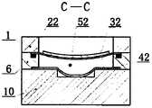
第一工作状态:第一压电振子、第三压电振子施加与压电陶瓷晶片极化方向相反的电压,第二压电振子施加与压电陶瓷晶片极化方向相同的电压,第一压电振子、第三压电振子向上弯曲变形,第二压电振子向下弯曲变形,第一介质腔和第三介质腔体积增大、压力减小,第一柔性薄膜、第三柔性薄膜在自身张力以及流体介质运动作用下收缩并向上运动,第二介质腔体积减小、压力增大,第二柔性薄膜在流体介质压力作用下膨胀并向下运动,如图5所示。The first working state: the first piezoelectric vibrator and the third piezoelectric vibrator apply a voltage opposite to the polarization direction of the piezoelectric ceramic wafer, the second piezoelectric vibrator applies a voltage in the same polarization direction as the piezoelectric ceramic wafer, and the first piezoelectric vibrator applies a voltage opposite to the polarization direction of the piezoelectric ceramic wafer. The electric vibrator and the third piezoelectric vibrator are bent and deformed upward, the second piezoelectric vibrator is bent and deformed downward, the volume of the first dielectric cavity and the third dielectric cavity increases, and the pressure decreases, and the first flexible film and the third flexible film are in their own Under the action of tension and the movement of the fluid medium, it contracts and moves upward, the volume of the second medium cavity decreases and the pressure increases, and the second flexible film expands and moves downward under the action of the pressure of the fluid medium, as shown in Figure 5.
第二工作状态:第一压电振子、第三压电振子施加与压电陶瓷晶片极化方向相同的电压,第二压电振子施加与压电陶瓷晶片极化方向相反的电压,第一压电振子、第三压电振子向下弯曲变形,第二压电振子向上弯曲变形,第一介质腔和第三介质腔体积减小、压力增大,第一柔性薄膜、第三柔性薄膜在流体介质压力作用下膨胀并向下运动,第二介质腔体积增大、压力减小,第二柔性薄膜在自身张力以及流体介质运动作用下收缩并向上运动,如图7所示。The second working state: the first piezoelectric vibrator and the third piezoelectric vibrator apply a voltage in the same polarization direction as the piezoelectric ceramic wafer, the second piezoelectric vibrator applies a voltage opposite to the polarization direction of the piezoelectric ceramic wafer, and the first piezoelectric vibrator applies a voltage opposite to the polarization direction of the piezoelectric ceramic wafer. The electric vibrator and the third piezoelectric vibrator are bent and deformed downward, the second piezoelectric vibrator is bent and deformed upward, the volume of the first medium cavity and the third medium cavity is reduced, and the pressure is increased, and the first flexible film and the third flexible film are in the fluid. Under the action of the medium pressure, it expands and moves downward, the volume of the second medium cavity increases and the pressure decreases, and the second flexible film shrinks and moves upward under the action of its own tension and the movement of the fluid medium, as shown in Figure 7.
所述第一压电振子、第二压电振子、第三压电振子分别由三个正弦电压信号驱动,相邻两个正弦电压信号的相位差为π,如图8所示。在交变电压信号的驱动下,第一工作状态、第二工作状态依次重复,进而实现凹槽内的持续蠕动血液输送。The first piezoelectric vibrator, the second piezoelectric vibrator, and the third piezoelectric vibrator are respectively driven by three sinusoidal voltage signals, and the phase difference of two adjacent sinusoidal voltage signals is π, as shown in FIG. 8 . Driven by the alternating voltage signal, the first working state and the second working state are repeated in sequence, thereby realizing continuous peristaltic blood delivery in the groove.
由于在工作过程中是通过流体介质带动柔性薄膜进行收缩和膨胀,一定程度上仿照了生物体器官组织的弹性,在驱动过程柔软温和,可以有效的避免血液破坏。Since the flexible film is driven by the fluid medium to shrink and expand during the working process, it imitates the elasticity of the organism's organs and tissues to a certain extent, and is soft and gentle during the driving process, which can effectively avoid blood damage.
本项目的特色及优势在于:①通过液体介质带动柔性薄膜,实现软体蠕动血液输送,可以有效的避免血液的破坏;②压电驱动、功耗低、结构简单、易集成且无电磁干扰。The features and advantages of this project are: ① The flexible film is driven by the liquid medium to realize the peristaltic blood transport of the soft body, which can effectively avoid the damage of blood; ② Piezoelectric drive, low power consumption, simple structure, easy integration and no electromagnetic interference.
附图说明:Description of drawings:
图1是本发明一种较佳实施例中蠕动泵的结构及剖面示意图;Fig. 1 is the structure and sectional schematic diagram of peristaltic pump in a kind of preferred embodiment of the present invention;
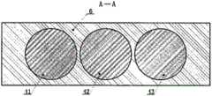
图2是图1中A-A的剖面示意图;Fig. 2 is the sectional schematic diagram of A-A in Fig. 1;
图3是图1中B-B的剖面示意图;Fig. 3 is the sectional schematic diagram of B-B in Fig. 1;
图4是本发明一种较佳实施例中下盖板的俯视图;4 is a top view of a lower cover plate in a preferred embodiment of the present invention;
图5是本发明一种较佳实施例中的第一工作状态示意图;5 is a schematic diagram of a first working state in a preferred embodiment of the present invention;
图6是图5中C-C的剖面示意图;Fig. 6 is the sectional schematic diagram of C-C in Fig. 5;
图7是本发明一种较佳实施例中的第二工作状态示意图;7 is a schematic diagram of a second working state in a preferred embodiment of the present invention;
图8是本发明一种较佳实施例中的驱动信号示意图;FIG. 8 is a schematic diagram of driving signals in a preferred embodiment of the present invention;
图标:1-上盖板;21-第一密封圈;22-第二密封圈;23-第三密封圈;300-金属基板;301-压电陶瓷晶片;31-第一压电振子;32-第二压电振子;33-第三压电振子;41-第一柔性薄膜;42-第二柔性薄膜;43-第三柔性薄膜;51-第一介质腔;52-第二介质腔;53-第三介质腔;6-介质腔板;7-第二缓冲腔;8-出口;9-凹槽;10-下盖板;11-第一缓冲腔;12-入口。Icon: 1-upper cover plate; 21-first sealing ring; 22-second sealing ring; 23-third sealing ring; 300-metal substrate; 301-piezoelectric ceramic chip; 31-first piezoelectric vibrator; 32 - the second piezoelectric vibrator; 33 - the third piezoelectric vibrator; 41 - the first flexible film; 42 - the second flexible film; 43 - the third flexible film; 51 - the first dielectric cavity; 52 - the second dielectric cavity; 53-third medium chamber; 6-medium chamber plate; 7-second buffer chamber; 8-outlet; 9-groove; 10-lower cover plate; 11-first buffer chamber; 12-inlet.
具体实施方式:Detailed ways:
下面将结合附图对本发明的技术方案进行清楚,完整的描述,需要说明的是,术语“中间”、“上”、“下”、“左”、“右”、“竖直”、“水平”、“内”、“外”等指示的方位或位置关系为基于附图所示的方位或位置关系,仅是为了便于描述本发明和简化描述,而不是指示或暗示所指的装置或元件必须具有特定的方位、以特定的方位构造和操作,因此不能理解为对本发明的限制。此外,术语“第一”、“第二”、“第三”仅用于描述目的,而不能理解为指示或暗示相对重要性。The technical solutions of the present invention will be clearly and completely described below with reference to the accompanying drawings. It should be noted that the terms "middle", "upper", "lower", "left", "right", "vertical", "horizontal" ", "inside", "outside", etc. indicate the orientation or positional relationship based on the orientation or positional relationship shown in the accompanying drawings, which are only for the convenience of describing the present invention and simplifying the description, rather than indicating or implying the indicated device or element. It must have a specific orientation, be constructed and operate in a specific orientation, and therefore should not be construed as a limitation of the present invention. Furthermore, the terms "first", "second", and "third" are used for descriptive purposes only and should not be construed to indicate or imply relative importance.
在本发明的描述中,需要说明的是,除非另有明确的规定和限定,术语“安装”、“相连”、“连接”应做广义理解,例如,可以是固定连接,也可以是可拆卸连接,或一体地连接;可以是机械连接,也可以是电连接;可以是直接相连,也可以通过中间媒介间接相连,可以是两个元件内部的连通。对于本领域的普通技术人员而言,可以具体情况理解上述术语在本发明中的具体含义。In the description of the present invention, it should be noted that the terms "installed", "connected" and "connected" should be understood in a broad sense, unless otherwise expressly specified and limited, for example, it may be a fixed connection or a detachable connection Connection, or integral connection; can be mechanical connection, can also be electrical connection; can be directly connected, can also be indirectly connected through an intermediate medium, can be internal communication between two elements. For those of ordinary skill in the art, the specific meanings of the above terms in the present invention can be understood in specific situations.
以下结合附图对本发明的具体实施方式进行详细说明。应当理解的是,此处所描述的具体实施方式仅用于说明和解释本发明,并不用于限制本发明。The specific embodiments of the present invention will be described in detail below with reference to the accompanying drawings. It should be understood that the specific embodiments described herein are only used to illustrate and explain the present invention, but not to limit the present invention.
下面将结合图1、图2、图3、图4、图5、图6、图7和图8对本发明的技术方案进行清楚、完整的描述,显然,所描述的实施例是本发明一部分实施例,而不是全部的实施例。如图1所示,上盖板1、介质腔板6和下盖板10从上至下依次连接;所述上盖板1和介质腔板6之间安装有第一压电振子31、第二压电振子32、第三压电振子33;所述第一压电振子31、第二压电振子32、第三压电振子33均由压电陶瓷晶片301和金属基板300同心粘接而成,且压电陶瓷晶片301的直径小于金属基板300的直径;所述介质腔板6上表面安装有第一密封圈21、第二密封圈22和第三密封圈23;所述第一密封圈21与第一压电振子31配套安装;所述第二密封圈22与第二压电振子32配套安装;所述第三密封圈23与第三压电振子33配套安装;所述介质腔板6从左至右设有第一介质腔51、第二介质腔52、第三介质腔53;所述介质腔板6下表面连接有第一柔性薄膜41、第二柔性薄膜42、第三柔性薄膜43;所述第一柔性薄膜41、第二柔性薄膜42、第三柔性薄膜43均为弹性硅胶膜;所述第一介质腔51连通第一压电振子31和第一柔性薄膜41;所述第一介质腔51是由第一压电振子31、介质腔板6和第一柔性薄膜41相连形成的密闭腔体;所述第二介质腔52连通第二压电振子32和第二柔性薄膜42;所述第二介质腔52是由第二压电振子32、介质腔板6和第二柔性薄膜42相连形成的密闭腔体;所述第三介质腔53连通第三压电振子33和第三柔性薄膜43;所述第三介质腔53是由第三压电振子33、介质腔板6和第三柔性薄膜43相连形成的密闭腔体;所述第一介质腔51、第二介质腔52、第三介质腔53内均填充有一定压力的流体介质,第一柔性薄膜41、第二柔性薄膜42、第三柔性薄膜43在流体介质压力作用下保持轻微凸起;需要说明的是,第一柔性薄膜41、第二柔性薄膜42、第三柔性薄膜43保持轻微凸起,这样既能保证在工作过程中的有效收缩,同时也能弥补流体介质由于温度产生的体积变化;所述下盖板10上表面设有凹槽9;所述凹槽9位于第一介质腔51、第二介质腔52、第三介质腔53的正下方;所述凹槽9的截面形状为矩形,如图3所示;所述第一柔性薄膜41、第二柔性薄膜42、第三柔性薄膜43的变形均作用于凹槽9内;所述凹槽9宽度a小于第一柔性薄膜41、第二柔性薄膜42和第三柔性薄膜43的工作直径d;需要说明的是,凹槽9宽度a小于柔性薄膜的工作直径d,这样可以让柔性薄膜获得位移放大的效果,即柔性薄膜的位移变形量会大于压电振子的位移变形量;所述第一柔性薄膜41、第二柔性薄膜42、第三柔性薄膜43在最大工作变形量时,其顶端能接触到凹槽9底部,如图6所示;所述凹槽9左端设有第一缓冲腔11;所述第一缓冲腔11与凹槽9连通;所述第一缓冲腔11与入口12连通;所述凹槽9右端设有第二缓冲腔7;所述第二缓冲腔7与凹槽9连通;所述第二缓冲腔7下方与出口8连通。The technical solution of the present invention will be clearly and completely described below with reference to Fig. 1, Fig. 2, Fig. 3, Fig. 4, Fig. 5, Fig. 6, Fig. 7 and Fig. 8. Obviously, the described embodiment is a part of the implementation of the present invention. examples, but not all examples. As shown in FIG. 1 , the
在工作过程中,蠕动泵的工作状态可分为初始状态、第一工作状态、第二工作状态。During the working process, the working state of the peristaltic pump can be divided into an initial state, a first working state, and a second working state.
初始状态:第一压电振子31、第二压电振子32、第三压电振子33处于不变形状态,第一柔性薄膜41、第二柔性薄膜42、第三柔性薄膜43在具有一定压力的流体介质作用下均轻微凸起。Initial state: the first
第一工作状态:第一压电振子31、第三压电振子33施加与压电陶瓷晶片301极化方向相反的电压,第二压电振子32施加与压电陶瓷晶片301极化方向相同的电压,第一压电振子31、第三压电振子33向上弯曲变形,第二压电振子32向下弯曲变形,第一介质腔51和第三介质腔53体积增大、压力减小,第一柔性薄膜41、第三柔性薄膜43在自身张力以及流体介质运动作用下收缩并向上运动,第二介质腔52体积减小、压力增大,第二柔性薄膜42在流体介质压力作用下膨胀并向下运动,如图5所示。The first working state: the first
第二工作状态:第一压电振子31、第三压电振子33施加与压电陶瓷晶片301极化方向相同的电压,第二压电振子32施加与压电陶瓷晶片301极化方向相反的电压,第一压电振子31、第三压电振子33向下弯曲变形,第二压电振子32向上弯曲变形,第一介质腔51和第三介质腔53体积减小、压力增大,第一柔性薄膜41、第三柔性薄膜43在流体介质压力作用下膨胀并向下运动,第二介质腔52体积增大、压力减小,第二柔性薄膜42在自身张力以及流体介质运动作用下收缩并向上运动,如图7所示。The second working state: the first
所述第一压电振子31、第二压电振子32、第三压电振子33分别由三个正弦电压信号驱动,相邻两个正弦电压信号的相位差为π,如图8所示。在三个交变电压信号的驱动下,第一工作状态、第二工作状态依次重复,进而实现凹槽9内的持续蠕动血液输送。The first
Claims (2)
Translated fromChinesePriority Applications (1)
| Application Number | Priority Date | Filing Date | Title |
|---|---|---|---|
| CN201910921058.2ACN110639075B (en) | 2019-09-20 | 2019-09-20 | Piezoelectric peristaltic pump for blood delivery |
Applications Claiming Priority (1)
| Application Number | Priority Date | Filing Date | Title |
|---|---|---|---|
| CN201910921058.2ACN110639075B (en) | 2019-09-20 | 2019-09-20 | Piezoelectric peristaltic pump for blood delivery |
Publications (2)
| Publication Number | Publication Date |
|---|---|
| CN110639075Atrue CN110639075A (en) | 2020-01-03 |
| CN110639075B CN110639075B (en) | 2022-06-10 |
Family
ID=69011584
Family Applications (1)
| Application Number | Title | Priority Date | Filing Date |
|---|---|---|---|
| CN201910921058.2AActiveCN110639075B (en) | 2019-09-20 | 2019-09-20 | Piezoelectric peristaltic pump for blood delivery |
Country Status (1)
| Country | Link |
|---|---|
| CN (1) | CN110639075B (en) |
Cited By (1)
| Publication number | Priority date | Publication date | Assignee | Title |
|---|---|---|---|---|
| CN111773459A (en)* | 2020-07-17 | 2020-10-16 | 江苏大学 | A flexible traveling wave driven cardiac micropump and its driving method |
Citations (9)
| Publication number | Priority date | Publication date | Assignee | Title |
|---|---|---|---|---|
| US5593290A (en)* | 1994-12-22 | 1997-01-14 | Eastman Kodak Company | Micro dispensing positive displacement pump |
| CN1840903A (en)* | 2005-03-31 | 2006-10-04 | 中国科学院空间科学与应用研究中心 | A piezoelectric film type fluid pump |
| CN201377412Y (en)* | 2009-04-24 | 2010-01-06 | 北京石油化工学院 | Single-diaphragm piezo pump for continuous fluid delivery |
| CN102597748A (en)* | 2009-08-25 | 2012-07-18 | 哈克兰格有限责任公司 | Water analyzer comprising a pneumatically driven multi-chamber peristaltic pump |
| CN102691693A (en)* | 2012-05-23 | 2012-09-26 | 浙江师范大学 | Precision stepping hydraulic cylinder driven by piezo-electricity wafer |
| CN202579118U (en)* | 2012-05-23 | 2012-12-05 | 浙江师范大学 | Serial pump for driving fluid on double sides of piezoelectric vibrator |
| CN103573593A (en)* | 2013-11-01 | 2014-02-12 | 刘勇 | Piezoelectric flexible diaphragm pump |
| CN204684305U (en)* | 2015-02-06 | 2015-10-07 | 吉林大学 | A kind of extracorporeal circulation apparatus of Piezoelectric Driving blood pump |
| CN108096664A (en)* | 2017-12-25 | 2018-06-01 | 浙江师范大学 | A kind of new separable piezoelectricity medical infusion pump |
- 2019
- 2019-09-20CNCN201910921058.2Apatent/CN110639075B/enactiveActive
Patent Citations (9)
| Publication number | Priority date | Publication date | Assignee | Title |
|---|---|---|---|---|
| US5593290A (en)* | 1994-12-22 | 1997-01-14 | Eastman Kodak Company | Micro dispensing positive displacement pump |
| CN1840903A (en)* | 2005-03-31 | 2006-10-04 | 中国科学院空间科学与应用研究中心 | A piezoelectric film type fluid pump |
| CN201377412Y (en)* | 2009-04-24 | 2010-01-06 | 北京石油化工学院 | Single-diaphragm piezo pump for continuous fluid delivery |
| CN102597748A (en)* | 2009-08-25 | 2012-07-18 | 哈克兰格有限责任公司 | Water analyzer comprising a pneumatically driven multi-chamber peristaltic pump |
| CN102691693A (en)* | 2012-05-23 | 2012-09-26 | 浙江师范大学 | Precision stepping hydraulic cylinder driven by piezo-electricity wafer |
| CN202579118U (en)* | 2012-05-23 | 2012-12-05 | 浙江师范大学 | Serial pump for driving fluid on double sides of piezoelectric vibrator |
| CN103573593A (en)* | 2013-11-01 | 2014-02-12 | 刘勇 | Piezoelectric flexible diaphragm pump |
| CN204684305U (en)* | 2015-02-06 | 2015-10-07 | 吉林大学 | A kind of extracorporeal circulation apparatus of Piezoelectric Driving blood pump |
| CN108096664A (en)* | 2017-12-25 | 2018-06-01 | 浙江师范大学 | A kind of new separable piezoelectricity medical infusion pump |
Cited By (1)
| Publication number | Priority date | Publication date | Assignee | Title |
|---|---|---|---|---|
| CN111773459A (en)* | 2020-07-17 | 2020-10-16 | 江苏大学 | A flexible traveling wave driven cardiac micropump and its driving method |
Also Published As
| Publication number | Publication date |
|---|---|
| CN110639075B (en) | 2022-06-10 |
Similar Documents
| Publication | Publication Date | Title |
|---|---|---|
| CN201162655Y (en) | Single-cavity dual-oscillator piezoelectric pump | |
| CN204402805U (en) | A kind of mode of resonance piezoelectricity diaphragm pump | |
| CN108953123B (en) | A kind of micro-pump structure based on PVC-gel flexible drive | |
| CN104832404A (en) | Piezoelectric micropump based on PDMS (Polydimethylsiloxane) | |
| JP2012107636A (en) | Piezoelectric micropump | |
| CN103671462A (en) | Piezoelectric valveless micropump suction cup based on parallel connection compliant mechanism | |
| CN110639075B (en) | Piezoelectric peristaltic pump for blood delivery | |
| CN108096664A (en) | A kind of new separable piezoelectricity medical infusion pump | |
| CN103511230B (en) | A kind of bicavate electric actuation valve free pump | |
| Li et al. | A broadband, high-power resonant piezoelectric active-valve pump driven by sandwich bending transducers | |
| CN110198662A (en) | Fluid control device and sphygmomanometer | |
| CN207960900U (en) | A kind of piezoelectric stack Micropump based on two level symmetrical expression flexible hinge enlarger | |
| CN114320845A (en) | A piezoelectric precision infusion pump integrating driving and sensing | |
| JPS61171891A (en) | Piezo-electric pump | |
| CN102562540A (en) | Diaphragm compressed valve-less micropump | |
| CN209892418U (en) | Axial-flow type miniature piezoelectric gas compressor | |
| Smits | Piezoelectric micropump with microvalves | |
| CN115350395A (en) | Variable flow direction's piezoelectricity valveless pump and controlling means thereof | |
| CN201377412Y (en) | Single-diaphragm piezo pump for continuous fluid delivery | |
| CN110665089A (en) | Electrostatic peristaltic pump for blood conveying | |
| CN216975182U (en) | Double resonant plunger pump | |
| CN206299550U (en) | Two-sided piezoelectric pump potsherd | |
| CN209892419U (en) | A hybrid cavity-driven miniature piezoelectric gas compressor | |
| CN2637765Y (en) | One way valve micro pump having no moving part | |
| CN102996418B (en) | Ultra-acoustic streaming micro-pump capable of realizing bidirectional flow |
Legal Events
| Date | Code | Title | Description |
|---|---|---|---|
| PB01 | Publication | ||
| PB01 | Publication | ||
| SE01 | Entry into force of request for substantive examination | ||
| SE01 | Entry into force of request for substantive examination | ||
| CB03 | Change of inventor or designer information | Inventor after:Luo Hanpin Inventor after:Liu Haidong Inventor after:Qian Chaoping Inventor after:Yu Mai Inventor after:Huang Zijian Inventor after:Chen Song Inventor before:Chen Song Inventor before:Liu Haidong Inventor before:Qian Chaoping Inventor before:Yu Mai Inventor before:Huang Zijian Inventor before:Luo Hanpin | |
| CB03 | Change of inventor or designer information | ||
| GR01 | Patent grant | ||
| GR01 | Patent grant |