CN110636801B - Suture package - Google Patents
Suture packageDownload PDFInfo
- Publication number
- CN110636801B CN110636801BCN201780089968.8ACN201780089968ACN110636801BCN 110636801 BCN110636801 BCN 110636801BCN 201780089968 ACN201780089968 ACN 201780089968ACN 110636801 BCN110636801 BCN 110636801B
- Authority
- CN
- China
- Prior art keywords
- package
- base member
- suture
- wall
- extending
- Prior art date
- Legal status (The legal status is an assumption and is not a legal conclusion. Google has not performed a legal analysis and makes no representation as to the accuracy of the status listed.)
- Active
Links
- 125000006850spacer groupChemical group0.000claimsdescription12
- 238000004804windingMethods0.000claimsdescription11
- 238000002360preparation methodMethods0.000claims1
- 238000000465mouldingMethods0.000abstract3
- 238000004806packaging method and processMethods0.000description9
- 230000014759maintenance of locationEffects0.000description5
- 238000000034methodMethods0.000description4
- 230000001954sterilising effectEffects0.000description4
- 238000004659sterilization and disinfectionMethods0.000description4
- 239000000463materialSubstances0.000description3
- 230000000845anti-microbial effectEffects0.000description2
- 230000004888barrier functionEffects0.000description2
- 238000000576coating methodMethods0.000description2
- 238000000605extractionMethods0.000description2
- 230000013011matingEffects0.000description2
- 238000012858packaging processMethods0.000description2
- 239000000123paperSubstances0.000description2
- 239000004033plasticSubstances0.000description2
- 229920003023plasticPolymers0.000description2
- -1polyethylenePolymers0.000description2
- 230000008569processEffects0.000description2
- 239000004677NylonSubstances0.000description1
- 239000004698PolyethyleneSubstances0.000description1
- 239000004743PolypropyleneSubstances0.000description1
- 241001422033ThestylusSpecies0.000description1
- 239000011248coating agentSubstances0.000description1
- 238000011161developmentMethods0.000description1
- 230000018109developmental processEffects0.000description1
- 239000000835fiberSubstances0.000description1
- 239000006260foamSubstances0.000description1
- 238000002347injectionMethods0.000description1
- 239000007924injectionSubstances0.000description1
- 238000003780insertionMethods0.000description1
- 230000037431insertionEffects0.000description1
- 229920001778nylonPolymers0.000description1
- 229920000728polyesterPolymers0.000description1
- 229920000573polyethylenePolymers0.000description1
- 229920000098polyolefinPolymers0.000description1
- 229920001155polypropylenePolymers0.000description1
- 238000001356surgical procedureMethods0.000description1
- 238000003856thermoformingMethods0.000description1
- 239000012815thermoplastic materialSubstances0.000description1
- 230000007704transitionEffects0.000description1
Images


Classifications
- A—HUMAN NECESSITIES
- A61—MEDICAL OR VETERINARY SCIENCE; HYGIENE
- A61B—DIAGNOSIS; SURGERY; IDENTIFICATION
- A61B17/00—Surgical instruments, devices or methods
- A61B17/04—Surgical instruments, devices or methods for suturing wounds; Holders or packages for needles or suture materials
- A61B17/06—Needles ; Sutures; Needle-suture combinations; Holders or packages for needles or suture materials
- A61B17/06114—Packages or dispensers for needles or sutures
- A61B17/06133—Packages or dispensers for needles or sutures of parallelepipedal shape, e.g. made of rectangular or slightly oval panels
- A—HUMAN NECESSITIES
- A61—MEDICAL OR VETERINARY SCIENCE; HYGIENE
- A61B—DIAGNOSIS; SURGERY; IDENTIFICATION
- A61B17/00—Surgical instruments, devices or methods
- A61B2017/00831—Material properties
- A61B2017/00902—Material properties transparent or translucent
- A—HUMAN NECESSITIES
- A61—MEDICAL OR VETERINARY SCIENCE; HYGIENE
- A61B—DIAGNOSIS; SURGERY; IDENTIFICATION
- A61B17/00—Surgical instruments, devices or methods
- A61B2017/00831—Material properties
- A61B2017/00902—Material properties transparent or translucent
- A61B2017/00907—Material properties transparent or translucent for light
- A—HUMAN NECESSITIES
- A61—MEDICAL OR VETERINARY SCIENCE; HYGIENE
- A61B—DIAGNOSIS; SURGERY; IDENTIFICATION
- A61B17/00—Surgical instruments, devices or methods
- A61B2017/00831—Material properties
- A61B2017/00955—Material properties thermoplastic
- A—HUMAN NECESSITIES
- A61—MEDICAL OR VETERINARY SCIENCE; HYGIENE
- A61B—DIAGNOSIS; SURGERY; IDENTIFICATION
- A61B17/00—Surgical instruments, devices or methods
- A61B17/04—Surgical instruments, devices or methods for suturing wounds; Holders or packages for needles or suture materials
- A61B17/06—Needles ; Sutures; Needle-suture combinations; Holders or packages for needles or suture materials
- A61B17/06114—Packages or dispensers for needles or sutures
- A61B2017/06142—Packages or dispensers for needles or sutures having needle- or suture- retaining members, e.g. holding tabs or needle parks
- A—HUMAN NECESSITIES
- A61—MEDICAL OR VETERINARY SCIENCE; HYGIENE
- A61B—DIAGNOSIS; SURGERY; IDENTIFICATION
- A61B90/00—Instruments, implements or accessories specially adapted for surgery or diagnosis and not covered by any of the groups A61B1/00 - A61B50/00, e.g. for luxation treatment or for protecting wound edges
- A61B90/08—Accessories or related features not otherwise provided for
- A61B2090/0813—Accessories designed for easy sterilising, i.e. re-usable
Landscapes
- Health & Medical Sciences (AREA)
- Surgery (AREA)
- Life Sciences & Earth Sciences (AREA)
- Biomedical Technology (AREA)
- Nuclear Medicine, Radiotherapy & Molecular Imaging (AREA)
- Engineering & Computer Science (AREA)
- Dentistry (AREA)
- Heart & Thoracic Surgery (AREA)
- Medical Informatics (AREA)
- Molecular Biology (AREA)
- Animal Behavior & Ethology (AREA)
- General Health & Medical Sciences (AREA)
- Public Health (AREA)
- Veterinary Medicine (AREA)
- Surgical Instruments (AREA)
Abstract
Translated fromChinese
Description
Translated fromChinese技术领域technical field
本发明涉及用于外科缝合线的包装。常规的外科缝合线和针包装具有几个有用的功能,包括在搬运、装运和储存过程中保护针和缝合线。此外,这些包装在应用之前在手术或其他医疗程序中便于接近并且释放针和缝合线。该包装可用于配有外科针的外科缝合线或不配针的无针外科缝合线。The present invention relates to packaging for surgical sutures. Conventional surgical suture and needle packaging has several useful functions, including protecting needles and sutures during handling, shipping, and storage. Additionally, these packages facilitate access and release needles and sutures during surgery or other medical procedures prior to application. The package can be used for surgical sutures with surgical needles or needleless surgical sutures without needles.
背景技术Background technique
用于带有或不带有针的外科缝合线的包装在本领域中是众所周知的。有两种类型的包装常规地用于外科针和缝合线。一种类型的包装是纸质文件夹包装,其中医用级纸板被折叠并切割成多个面板。然后将缝合线缠绕在面板上,然后通过首先将面板折叠成所需的构造,然后使用切割到面板中的狭缝和锁定凸片将面板锁定在适当的位置,来组装包装。Packaging for surgical sutures with or without needles is well known in the art. There are two types of packaging routinely used for surgical needles and sutures. One type of packaging is paper folder packaging, where medical grade cardboard is folded and cut into multiple panels. The seam is then wrapped around the panel and the package is assembled by first folding the panel into the desired configuration, then using the slits and locking tabs cut into the panel to lock the panel in place.
已经使用的另一种缝合线包装是具有缠绕通道的托盘包装。这些托盘包装通常具有椭圆形状,外壁和内壁形成椭圆形缠绕通道。包装通常由塑料模制而成。包装被安装到缠绕夹具上,然后缝合线被缠绕到缠绕通道中。缝合线包装通常具有用于安装和固定外科针的针存放构件,如果外科针安装到缝合线上的话。常规的针存放部可以由泡沫构件或等效的保持结构组成。针存放构件也可用于安装缝合线的缠绕到缠绕通道中的一端。Another suture package that has been used is a tray package with winding channels. These tray packs typically have an oval shape with outer and inner walls forming an oval winding channel. Packaging is usually molded from plastic. The package is mounted on the winding jig, and the suture is then wound into the winding channel. Suture packages typically have a needle storage member for mounting and securing a surgical needle, if mounted to the suture. Conventional needle storage may consist of a foam member or equivalent retention structure. The needle storage member may also be used to install the end of the suture that is wound into the winding channel.
美国专利No.4,961,498公开了一种具有椭圆形缠绕通道的两件式缝合线包装。美国专利No.4,967,902公开了一种单件式通道缝合线包装,其具有将缝合线保持在通道中的多个门构件。美国专利No.5,230,424公开了一种包装,该包装具有基本上正方形的形状和正方形的缝合线通道,其中多个悬臂式门安装在内壁上以保持缝合线在通道中。美国专利No.5,655,652公开了一种具有椭圆形缠绕通道的包装,具有顶部摩擦板构件来代替门或悬臂式门。US Patent No. 4,961,498 discloses a two-piece suture package with an oval wrap channel. US Patent No. 4,967,902 discloses a one-piece channel suture package having multiple door members that retain the suture in the channel. US Patent No. 5,230,424 discloses a package having a substantially square shape and a square suture channel with a plurality of cantilevered doors mounted on the inner wall to retain the suture in the channel. US Patent No. 5,655,652 discloses a package with an oval winding channel with a top friction plate member in place of a door or cantilevered door.
美国专利No.5,131,533公开了一种具有铰接部段的针存放部。美国专利No.5,180,053公开了一种具有悬臂针存放部的缝合线包装。这个存放部相对于包装的基底竖向地延伸。这种类型的存放部的缺点是,如果包装在运输过程中挠曲,针会释放。US Patent No. 5,131,533 discloses a needle storage portion having a hinged section. US Patent No. 5,180,053 discloses a suture package having a cantilever needle storage. This storage extends vertically with respect to the base of the package. The disadvantage of this type of storage is that if the package is deflected during transport, the needle can release.
美国专利No.6,135,272公开了多个悬臂式覆盖门构件,它们之间有空间。这些门构件有一个缺点:如果触针高速移动会变形,从而限制缠绕速度。US Patent No. 6,135,272 discloses a plurality of cantilevered cover door members with spaces between them. These gate members have a disadvantage: if the stylus is moved at high speed, it deforms, thus limiting the winding speed.
WO2013/049400 A1公开了一种具有两个半件的缝合线包装。主体部分的内部在主体部分的一个半件处设有一对柱,在主体部分的另一个半件处设有相应的一对配合凸台。当基座的两个半件被压在一起时,柱以压配合或卡扣配合的方式配合到凸台中,以将两个半件固定在一起。柱和凸台还提供了缝合线股绕其卷绕的结构。WO2013/049400 A1 discloses a suture package with two halves. The interior of the body portion is provided with a pair of posts at one half of the body portion and a corresponding pair of mating bosses at the other half of the body portion. When the two halves of the base are pressed together, the post fits into the boss in a press fit or snap fit to secure the two halves together. The posts and bosses also provide structure around which the suture strands are wound.
EP 2 172 157 A1公开了一种用于保持倒钩缝合线的缝合线包装,包括具有外壁和内壁的缝合线保持构件。内壁与外壁径向间隔开,并在其间限定缝合线保持区域。外壁包括多个向内延伸的凸片,这些凸片被构造成接合覆盖物。缝合线包装还包括被构造成接纳在缝合线保持构件的外壁内,并选择性地接合形成在其上的向内延伸的凸片的覆盖物。
EP 3 095 392 A1公开了一种用于缝合线的包装,该包装具有缠绕通道,通过使外侧壁和圆柱形支座构件的内行形成用于缝合线的通道而产生缠绕通道。包装具有基底构件和扁平的覆盖构件,覆盖构件通过位于圆柱形支座构件顶部的多个卡扣锁安装到基底构件上。基底构件的边缘具有沿着外侧壁的覆盖物锁定凸片。EP 3 095 392 A1 discloses a package for sutures having a winding channel created by forming the channel for the suture with the outer side wall and the inner row of the cylindrical support member. The package has a base member and a flat cover member that is mounted to the base member by a plurality of snap locks on top of the cylindrical standoff member. The edge of the base member has cover locking tabs along the outer sidewall.
尽管现有技术的缝合线托盘包装对于它们的预期用途来说是足够和有效的,但是这种包装也有缺点。一种可能出现的问题的示例是当外科医生试图从包装中取出缝合线时,缝合线“挂住(hang-up)”。因此,在本领域中需要具有缠绕通道的新颖缝合线托盘包装,该缠绕通道易于适应高速包装过程,其克服了现有技术包装的缺点,包括与缝合线取出相关的问题。因此,需要气体能够容易地围绕缝合线流动,以便于灭菌和抗菌涂布。While prior art suture tray packages are adequate and efficient for their intended use, such packages also have disadvantages. An example of a possible problem is the suture "hang-up" when the surgeon attempts to remove the suture from the package. Accordingly, there is a need in the art for a novel suture tray package having a wrapping channel that readily accommodates high-speed packaging processes that overcomes the shortcomings of prior art packaging, including problems associated with suture extraction. Therefore, there is a need for gas to flow easily around the suture to facilitate sterilization and antimicrobial coating.
发明内容SUMMARY OF THE INVENTION
从这个先前已知的现有技术出发,本发明的一个目的是提供一种具有缠绕通道的新颖托盘包装,其在用于包装外科缝合线的高速包装过程中是有用的。Proceeding from this previously known prior art, it is an object of the present invention to provide a novel tray package with winding channels that is useful in high speed packaging processes for packaging surgical sutures.
本发明的另一个目的是提供一种托盘包装,该托盘包装能够牢固地将缝合线保持在具有开放内壁的通道中,以便于灭菌应用和/或抗菌涂覆的施加。Another object of the present invention is to provide a tray package capable of securely retaining a suture in a channel with open inner walls for sterilization applications and/or application of antimicrobial coatings.
本发明的又一个目的是提供一种新颖的缝合线托盘包装,其便于缝合线从包装中取出。Yet another object of the present invention is to provide a novel suture tray package that facilitates removal of the suture from the package.
本发明的再一个目的是提供一种新颖的针存放部,以在搬运过程中更好地固持针。Yet another object of the present invention is to provide a novel needle storage to better retain needles during handling.
根据本发明的缝合线包装由主权利要求的特征产生。本发明的适当发展是主权利要求之后的进一步权利要求的主题。A suture package according to the invention results from the features of the main claim. Appropriate developments of the invention are the subject of further claims following the main claim.
因此,公开了一种缝合线包装。该包装具有基底构件,该基底构件具有顶表面、底表面、外周和纵向轴线。外壁围绕所述基底构件的周围向上延伸,所述外壁具有内表面、外表面和顶部。内部多个棱锥形支座构件布置成椭圆形,其限定并捕获缝合线,从而形成缝合线要位于其中的通道。Accordingly, a suture package is disclosed. The package has a base member having a top surface, a bottom surface, a periphery and a longitudinal axis. An outer wall extends upwardly around the circumference of the base member, the outer wall having an inner surface, an outer surface and a top. An inner plurality of pyramid-shaped standoff members are arranged in an oval shape that defines and captures the suture, thereby forming a channel in which the suture is to be located.
还有一个扁平纸缝合线通道覆盖构件,用于安装到基底构件上。缝合线通道覆盖构件具有顶表面、底表面和外周。覆盖构件中存在多个精确孔,以将所述覆盖构件锁定到基底构件的支座构件上。具有第一端和第二端的端口引出开口位于外轨道壁中并形成缝合线端口。There is also a flat paper suture channel cover member for mounting to the base member. The suture channel covering member has a top surface, a bottom surface and an outer periphery. A number of precise holes are present in the cover member to lock the cover member to the abutment member of the base member. A port extraction opening having a first end and a second end is located in the outer track wall and forms a suture port.
针存放装置从基底构件的顶表面位于支座构件的内部。The needle storage device is located inside the stand member from the top surface of the base member.
通过将覆盖构件紧固件孔与基底构件支座构件对准并将支座构件的顶部插入覆盖构件的精确孔中,覆盖构件被安装到基底构件上以形成本发明的包装。例如,支座构件可以通过使用超声波来变形。这使支座构件的顶部变平和变宽,从而防止覆盖构件从支座构件上滑落。这在基底构件外壁的内表面、基底构件的顶表面、支座构件的外侧和缝合线覆盖构件的底表面之间形成缝合线通道。The cover member is mounted to the base member to form the package of the present invention by aligning the cover member fastener holes with the base member seat member and inserting the top of the seat member into the precise hole in the cover member. For example, the support member can be deformed by using ultrasonic waves. This flattens and widens the top of the stand member, thereby preventing the cover member from slipping off the stand member. This forms a suture channel between the inner surface of the outer wall of the base member, the top surface of the base member, the outer side of the standoff member, and the bottom surface of the suture covering member.
可选的塑料顶部缝合线覆盖物可以用来完成组装好的包装。在缝合线缠绕到由覆盖构件、基底构件的外壁、基底构件的顶表面和支座构件形成的通道中之后,该组装完成。An optional plastic top seam covering can be used to complete the assembled package. The assembly is complete after the suture is wound into the channel formed by the cover member, the outer wall of the base member, the top surface of the base member, and the standoff member.
从以下描述和附图中,本发明的这些和其他特征和优点将变得更加明显。These and other features and advantages of the present invention will become more apparent from the following description and accompanying drawings.
外壁的成型表面可以由从基底构件的顶表面延伸到外壁顶部的多个凸起组成。这些凸起可以是D形竖向构件。在一个包装中,D形竖向构件的长度可以变化。D形竖向构件应该从基底构件的外壁突出至少一毫米,以便提供互锁屏障,该屏障将包含尺寸小至10/0的缝合线,并将缝合线保持在包装内。The contoured surface of the outer wall may consist of a plurality of protrusions extending from the top surface of the base member to the top of the outer wall. These protrusions may be D-shaped vertical members. In a package, the length of the D-shaped vertical members can vary. The D-shaped vertical members should protrude at least one millimeter from the outer wall of the base member in order to provide an interlocking barrier that will contain sutures down to
包装可以包括基底构件的缝合线轨道区域中的多个空气槽。在这种情况下,可以存在从外壁的内表面向内延伸的多个锁定构件。这些锁定构件可以位于空气槽的正上方,因此整个基底构件可以在一个模具中生产。包装的覆盖构件可以位于那些锁定构件的下方,以便将覆盖构件紧固到基底构件上。替代地或附加地,可以有至少一个凸片构件从支座构件的外表面向外延伸并面向外壁的内表面。这些凸片构件也可以位于基底构件的空气槽正上方。包装的覆盖构件可以定位在至少一个凸片构件的上方,以便更好地限定覆盖构件与基底构件的顶表面之间的距离。此外,一旦移除覆盖构件,这些凸片构件可以防止缝合线离开缝合线轨道区域。The package may include a plurality of air slots in the suture track area of the base member. In this case, there may be a plurality of locking members extending inwardly from the inner surface of the outer wall. These locking members can be located directly above the air slots so that the entire base member can be produced in one mould. Covering members of the package may be located below those locking members to secure the covering member to the base member. Alternatively or additionally, there may be at least one tab member extending outwardly from the outer surface of the standoff member and facing the inner surface of the outer wall. These tab members may also be located directly above the air grooves of the base member. The cover member of the package may be positioned over the at least one tab member to better define the distance between the cover member and the top surface of the base member. Additionally, these tab members can prevent the suture from leaving the suture track area once the cover member is removed.
可以有至少一个间隔件从基底构件的内表面延伸,每个间隔件具有顶部、底部和外表面,所述间隔件布置在两个支座构件之间。所述间隔件彼此结合并且与支座构件中至少一些结合可以形成缝合线轨道区域的内壁。There may be at least one spacer extending from the inner surface of the base member, each spacer having a top, bottom and outer surface, the spacer being disposed between the two standoff members. The spacers, in combination with each other and with at least some of the standoff members, may form an inner wall of the suture track region.
基底构件的支座构件可以成形为截头棱锥。The support member of the base member may be shaped as a truncated pyramid.
基底构件可以是透明的。这使得包装的使用者能够更好地看到缝合线和针的位置。此外,缝合线和针的种类可以通过透明基底构件看到。The base member may be transparent. This allows the user of the package to better see where the sutures and needles are. Additionally, the types of sutures and needles can be seen through the transparent base member.
覆盖构件可以包括用于接纳缠绕销的孔。The cover member may include holes for receiving the wrapping pins.
包装可能已经包括缠绕在缠绕通道中的缝合线和安装在针存放装置中的外科针。The package may already include the suture wrapped in the wrap channel and the surgical needle installed in the needle storage device.
包装可以具有椭圆形构造。The package may have an oval configuration.
针存放构件可以包括从基底构件的顶表面延伸的至少一个悬臂式水平臂和用于将针固定在针存放构件的至少一个水平臂下方的保持构件。保持构件可以包括在至少一个水平臂的底侧的凹入区域和在基底构件的顶表面的至少一个卡扣。The needle storage member may include at least one cantilevered horizontal arm extending from the top surface of the base member and a retention member for securing the needle under the at least one horizontal arm of the needle storage member. The retention member may include a recessed area on the bottom side of the at least one horizontal arm and at least one snap on the top surface of the base member.
附加地或替代地,针存放构件可以包括彼此对准的至少一个第一腹板和至少一个第二腹板。彼此面对的第一端和第二端的端部可以形成为夹紧装置。例如,第一腹板的面向第二腹板的端部可以包括凹入区域,第二腹板的面向第一腹板的端部可以包括凸出区域。Additionally or alternatively, the needle storage member may include at least one first web and at least one second web aligned with each other. The ends of the first and second ends facing each other may be formed as clamping means. For example, the end of the first web facing the second web may include a concave area and the end of the second web facing the first web may include a convex area.
本发明的其他优点和特征可以从权利要求中进一步指定的特征和以下示例性实施例中取得。Other advantages and features of the invention may be obtained from the features further specified in the claims and from the following exemplary embodiments.
附图说明Description of drawings
在下文中,将使用附图中所示的示例性实施例更详细地描述和解释本发明。In the following, the present invention will be described and explained in more detail using exemplary embodiments shown in the accompanying drawings.
图1是包装的第一实施例的俯视平面图,该包装中安装有带缝合线的针。Figure 1 is a top plan view of a first embodiment of a package in which a needle with suture is installed.
图2是图1中包装的基底构件的俯视图。FIG. 2 is a top view of the base member of the package of FIG. 1 .
图3是图1中包装的覆盖构件的俯视图。FIG. 3 is a top view of the cover member of the package of FIG. 1 .
图4是图1中包装的基底构件的放大视图,示出了针存放装置。Figure 4 is an enlarged view of the base member of the package of Figure 1 showing the needle storage device.
图5是穿过图4的针存放装置之一的截面图。FIG. 5 is a cross-sectional view through one of the needle storage devices of FIG. 4 .
图6是在覆盖构件固定到支座构件之前穿过支座构件之一的截面图。Figure 6 is a cross-sectional view through one of the standoff members before the cover member is secured to the standoff member.
图7是在覆盖构件固定到图6的支座构件之后穿过该支座构件的截面图。FIG. 7 is a cross-sectional view through the seat member of FIG. 6 after the cover member is secured to the seat member.
图8是包装的第二实施例的基底构件的俯视图。Figure 8 is a top view of the base member of the second embodiment of the package.
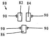
图9是图8中基底构件的放大视图,示出了针存放装置。Figure 9 is an enlarged view of the base member of Figure 8 showing the needle storage device.
图10是包装的第三实施例的基底构件的一部分的放大透视图。Figure 10 is an enlarged perspective view of a portion of the base member of the third embodiment of the package.
具体实施方式Detailed ways
根据本发明第一实施例的包装10在图1至图7中示出。如图1、图6和图7所示,包装10具有基底构件12和扁平缝合线通道覆盖构件14。A
现在更详细地参考图2,可以看到基底构件12具有顶表面20和底表面。还可以看到基底构件12具有外周22。看出基底构件12为具有纵向轴线24的基本扁平且基本椭圆形的构件。然而,尽管期望基底构件12和包装10是椭圆形的,但是也可以使用其他构造,包括圆形、多边形、带倒圆拐角的正方形等及其组合和等效物。Referring now in more detail to FIG. 2, the
外壁30围绕基底构件12的周围22向上延伸。可以看到外壁30具有底部、内表面32、外表面34和顶部36。外壁30的内表面32是具有从基底构件12的顶表面20延伸到外壁30的顶部36的多个D形凸起38的成型表面。D形凸起38从外壁30突出至少一毫米。The
基底构件12的外壁30的顶部可以有可选的凹口。这些凹口用于保持基底构件12扁平。The top of the
在图2中,可以看到支座构件40从基底构件12的顶表面20向上延伸。根据图6,支座构件40具有棱锥形外表面42和平坦顶部44。In FIG. 2 , the
支座构件40的顶部44优选与外壁30的顶部36齐平。The top 44 of the
多个空气槽50延伸穿过基底构件12的底部(见图2)。空气槽50位于外壁30与支座构件40之间。圆形缠绕驱动销定位孔52和椭圆形驱动销定位孔54也延伸穿过基底构件12的底部。可以看到孔52和54沿着纵向轴线24设置,并且位于基底构件12的相对端。外壁30内部的基底构件12的底部中的可选狭缝可以形成凸片提升构件56。A plurality of
此外,悬臂式间隔件58位于支座构件中的两个之间。间隔件58限定了当覆盖构件14被向下推到基底构件12上至尽可能低的程度时的位置。如图2所示,可以有一个间隔件58,或者可以有更多的间隔件58均匀地分布在基底构件12的顶表面20上。Additionally, a cantilevered
现在参考图3,可以看到缝合线通道覆盖构件14被示出。缝合线通道覆盖构件14具有顶表面60、底表面和周围62。基底构件外壁30的D形凸起38在覆盖构件14的外周62中具有镜像切口。当组装时,覆盖构件14中的那些匹配凹陷64提供互锁屏障,其将包含尺寸小至10/0的缝合线,并将缝合线保持在包装10内。Referring now to FIG. 3, it can be seen that the suture
可以看到销缠绕孔66和68包含在覆盖构件14的相对端。可以看到销缠绕孔66和68延伸穿过覆盖构件14,并且沿着覆盖构件14的纵向轴线70朝向两端设置在覆盖构件14中。它们与基底构件12中的缠绕驱动销孔52、54对齐。销缠绕孔66是圆形的,而销缠绕孔68是椭圆形的。然而,也可以使用其他几何形状。It can be seen that pin wrap holes 66 and 68 are included on opposite ends of the
可以看到缝合线引出端口72包含在覆盖构件14中。还可以看到延伸穿过覆盖构件14的精确孔74,精确孔74与基底构件12的支座构件40配合。精确孔74的直径和形状由支座构件40的形状决定。例如,为了将覆盖构件14锁定到基底构件12,支座构件40的顶部44通过使用超声波变形。这使支座构件40的顶部44变平和变宽(见图7)。在支座构件40的顶部44变形之后,覆盖构件的精确孔74不能从支座构件40上滑落,因此覆盖构件14被牢固地锁定到基底构件12上。The
有多个缝合线缠绕销孔76延伸穿过覆盖构件14。缝合线缠绕销孔76位于外周62与精确孔74之间。缝合线缠绕销孔76的优选形状是圆形的,但是也可以使用其他形状,例如椭圆形、八边形、半圆形、多边形、三角形、它们的组合及其等效物等。There are a plurality of suture wrap pin holes 76 extending through the
为了保持对小针的控制,示出了基底构件12中的新颖针存放部80。图4和图5中的针存放部80显示为具有三个水平悬臂82、84、86的优选构造。每个水平臂82、84、86在其底侧具有凹入区域88(见图5)。水平悬臂82、84、86的两侧有从基底构件12的顶表面20升起的成角度斜坡形式的卡扣90。这些斜坡90防止较小的针在运输过程中移动或过早释放。To maintain control of the small needle, a
本发明的包装10以下列方式组装。针92被放置在针存放部的水平悬臂82、84、86中的至少一个中。然后,缝合线94被穿入外壁30的内表面32与支座构件40之间的基底构件12的缠绕通道16中。在缠绕过程中,通过空气槽50施加负压,以将缝合线94保持在缠绕通道16中。接下来,缝合线通道覆盖构件12通过常规方式印刷,并且覆盖构件14的销缠绕孔66、68与基底构件12的缠绕驱动销定位孔52、54对准。缝合线94缠绕完成后,覆盖构件14被向下推到基底构件12上,直到精确孔74与支座构件40的外表面42接触。在仍然施加负压的同时,支座构件40的顶部44变形,以便将覆盖构件14锁定到基底构件12。The
然后,包含缠绕缝合线94和针92的包装10可以被放置在常规的袋或包装中,用于常规的灭菌处理,例如气态杀菌剂、高压灭菌、辐射等。The
图8和图9示出了根据本发明第二实施例的包装的基底构件12.2。如图8所示的基底构件12.2可以与类似于图3所示的覆盖构件12的覆盖构件组合。Figures 8 and 9 show a base member 12.2 of a package according to a second embodiment of the invention. The base member 12.2 shown in Figure 8 may be combined with a cover member similar to the
可以看到基底构件12.2具有顶表面20.2和底表面。还可以看到基底构件12.2具有外周22。基底构件12.2被视为具有纵向轴线24的基本扁平且基本椭圆形的构件。The base member 12.2 can be seen to have a top surface 20.2 and a bottom surface. It can also be seen that the
外壁30.2围绕基底构件12.2的周围22向上延伸。外壁30.2的内表面32.2是具有从基底构件12.2的顶表面20.2延伸到外壁30.2的顶部36的多个D形凸起38、39的成型表面。D形凸起38、39从外壁30.2突出至少一毫米。D形凸起38大致为半圆形,而D形凸起39长得多。在图8中,四个D形凸起39位于直的中间部段与圆形端部段之间的基底构件12.2的过渡区域中。与此相反,可以具有或多或少的较长的D形凸起39,并且它们可以随意定位。The outer wall 30.2 extends upwardly around the
在图8中,可以看到支座构件40从基底构件12.2的顶表面20.2向上延伸。支座构件40具有棱锥形外表面42和平坦顶部44。支座构件40的顶部44优选与外壁30.2的顶部36齐平。大多数支座构件40是内壁区域46的一部分。内壁区域46的顶部位于外壁30.2的顶部36下方,并且也在支座构件40的顶部44下方。因此,内壁区域46可以限定当覆盖构件被向下推到基底构件12.2上至尽可能低的程度时的位置。此外,内壁区域46可以便于取出缝合线。In Figure 8, the
多个空气槽50.2延伸穿过基底构件12.2的底部。空气槽50.2位于外壁30.2与带有支座构件40的内壁区域46之间。空气槽50.2位于缝合线轨道通道16中。圆形缠绕驱动销定位孔52和椭圆形驱动销定位孔54也延伸穿过基底构件12.2的底部。椭圆形驱动销定位孔54也延伸穿过基底构件12.2的内壁区域46。可以看到孔52和54沿着纵向轴线24设置,并且位于基底构件12.2的相对端。基底构件12.2的底部中内壁区域46内部的可选狭缝可以形成凸片提升构件56。A plurality of air slots 50.2 extend through the bottom of the base member 12.2. The air slot 50.2 is located between the outer wall 30.2 and the
为了便于针的插入,示出了基底构件12.2中的新颖针存放部80.2。图9中的针存放部80.2以其优选构造示出,其中第一腹板100、第二腹板102和第三腹板104彼此对准。腹板100在面对第二纤维腹板102的一端包括凹入区域106。第二腹板102在面对第一腹板100的一端上包括凸出区域108和在面对第三腹板104的一端上包括凹入区域110。第三腹板104在面对第二腹板102的一端包括凸出区域112。一个腹板102、104的凸出区域108、112和相应腹板100、102的相对应凹入区域106、110形成针92的夹紧装置。针92可以位于凹入区域106、110与凸出区域108、112之间,以便固定在包装中。To facilitate needle insertion, a novel needle storage 80.2 in the base member 12.2 is shown. The needle store 80.2 in Figure 9 is shown in its preferred configuration, wherein the
可以将根据图4和图5的针存放部80和根据图9的针存放部80.2组合在一个基底构件中。例如,根据图9的针存放部80.2可以与根据图4的水平悬臂86的两侧的一个水平悬臂86和两个成角度的斜坡组合。The
图10示出了根据本发明第三实施例的包装的基底构件12.3。如图10所示的基底构件12.3可以与类似于图3所示的覆盖构件12的覆盖构件组合。Figure 10 shows a base member 12.3 of a package according to a third embodiment of the invention. The base member 12.3 shown in Figure 10 may be combined with a cover member similar to the
可以看到基底构件12.3具有顶表面20.3和底表面。还可以看到基底构件12.3具有外周22。基底构件12.3被视为具有纵向轴线24的基本扁平且基本椭圆形的构件。外壁30围绕基底构件12.3的周围22向上延伸。基底构件12.3的外壁30与根据图1和2的基底构件12的外壁30相同。还可以将根据图8的基底构件12.2的外壁30.2与根据图10的基底构件12.3组合。The base member 12.3 can be seen to have a top surface 20.3 and a bottom surface. It can also be seen that the base member 12.3 has an
在图10中,可以看到支座构件40从基底构件12.3的顶表面20.3向上延伸。支座构件40具有棱锥形外表面42和平坦顶部44。支座构件40的顶部44优选与外壁30的顶部36齐平。位于基底构件12.3的圆形端部段处的支座构件40是内壁48的一部分。内壁48的顶部位于外壁30.2的顶部36下方,也位于支座构件40的顶部44下方。因此,内壁48可以限定当覆盖构件被向下推到基底构件12.3上至尽可能低的程度时的位置。此外,内壁48可以便于取出缝合线。In Figure 10, the
多个空气槽50.2延伸穿过基底构件12.3的底部。空气槽50.2位于外壁30.2与带有支座构件40的内壁48之间。空气槽50.2位于缝合线轨道通道16中。凸片构件120从支座构件40的外表面42向外延伸。凸片构件120面向外壁30的内表面32。凸片构件120位于空气槽50.2上方,因此整个基底构件12.3可以在一个模具中生产。为了更好地限定覆盖构件与基底构件12.3的顶表面20.3之间的距离,覆盖构件可以定位在凸片构件120的上方。此外,一旦移除覆盖构件,这些凸片构件120可以防止缝合线离开缝合线轨道区域16。A plurality of air slots 50.2 extend through the bottom of the base member 12.3. The air slot 50.2 is located between the outer wall 30.2 and the
与图10所示的实施例不同,这些凸片件120也可以与没有内壁48(如图1和图2所示)的支座部件40组合,或者与包括在内壁区域46中的支座部件40组合(如图8所示)。Unlike the embodiment shown in FIG. 10 , these
可以有从基底构件外壁的内表面向内延伸的锁定构件。这些锁定构件也应该位于基底构件的空气槽上方,以便整个基底构件可以在一个模具中生产。包装的覆盖构件可以定位在那些锁定构件下方,以便将覆盖构件紧固到基底构件。这些锁定构件可以与支座构件的凸片构件组合,并且它们也可以与如图8所示的不同的D形竖向构件38、39组合。There may be locking members extending inwardly from the inner surface of the outer wall of the base member. These locking members should also be located above the air grooves of the base member so that the entire base member can be produced in one mould. Covering members of the package may be positioned below those locking members to secure the covering members to the base member. These locking members can be combined with the tab members of the abutment members, and they can also be combined with the different D-shaped
本发明包装10的基底构件12可以由常规的可模制材料制成。特别优选使用聚烯烃材料,例如聚乙烯和聚丙烯、其他热塑性材料和聚酯材料如尼龙及其等效物。优选地,本发明的基底构件12是注射模制的,然而,基底构件12可以通过包括热成型在内的其他常规过程及其等效过程形成。如果需要,包装10可以制造成分立的组件或部件,然后组装。The
可以包装在本发明的包装10中的缝合线和针包括常规外科针和常规生物可吸收和不可吸收外科缝合线及其等效物。本发明的包装10可用于包装小直径缝合线,这些缝合线以前很难包装在托盘包装中,因为从包装中取出这些缝合线时会出现移除或挂住的问题。使用本发明的包装10已经克服了这些问题。Sutures and needles that can be packaged in the
Claims (17)
Applications Claiming Priority (1)
| Application Number | Priority Date | Filing Date | Title |
|---|---|---|---|
| PCT/EP2017/000509WO2018196940A1 (en) | 2017-04-24 | 2017-04-24 | Package for sutures |
Publications (2)
| Publication Number | Publication Date |
|---|---|
| CN110636801A CN110636801A (en) | 2019-12-31 |
| CN110636801Btrue CN110636801B (en) | 2022-08-30 |
Family
ID=58671564
Family Applications (1)
| Application Number | Title | Priority Date | Filing Date |
|---|---|---|---|
| CN201780089968.8AActiveCN110636801B (en) | 2017-04-24 | 2017-04-24 | Suture package |
Country Status (6)
| Country | Link |
|---|---|
| US (1) | US10835237B2 (en) |
| EP (1) | EP3589216B1 (en) |
| CN (1) | CN110636801B (en) |
| CA (1) | CA3059383C (en) |
| ES (1) | ES2874258T3 (en) |
| WO (1) | WO2018196940A1 (en) |
Families Citing this family (3)
| Publication number | Priority date | Publication date | Assignee | Title |
|---|---|---|---|---|
| WO2020183411A1 (en)* | 2019-03-13 | 2020-09-17 | Hamed Jafarishad | Suture package |
| WO2024172130A1 (en) | 2023-02-17 | 2024-08-22 | マニー株式会社 | Armed suture spooling device, armed suture housing tray, and medical instrument housing tray |
| WO2025171459A1 (en)* | 2024-02-13 | 2025-08-21 | Общество с ограниченной ответственностью "ФУТБЕРГ" | Package for surgical suture material |
Citations (6)
| Publication number | Priority date | Publication date | Assignee | Title |
|---|---|---|---|---|
| CN201234991Y (en)* | 2008-07-23 | 2009-05-13 | 孙桂芝 | Operation line fixing box |
| CN101711698A (en)* | 2008-10-02 | 2010-05-26 | Tyco医疗健康集团 | suture packaging |
| CN203388901U (en)* | 2013-08-08 | 2014-01-15 | 天津市儿童医院 | Tray for surgical suture needles and sutures |
| WO2015138966A1 (en)* | 2014-03-13 | 2015-09-17 | Surgical Specialties Corporation | Multiple panel suture dispensing card and method for using the same |
| CN105193464A (en)* | 2014-06-19 | 2015-12-30 | Smeng株式会社 | Medical Suture Package |
| EP3095392A1 (en)* | 2015-05-18 | 2016-11-23 | DS-Technology GmbH | Package for sutures |
Family Cites Families (13)
| Publication number | Priority date | Publication date | Assignee | Title |
|---|---|---|---|---|
| US4961498A (en) | 1988-08-24 | 1990-10-09 | Ethicon, Inc. | Oval wrap suture package |
| US4967902A (en) | 1989-09-12 | 1990-11-06 | Ethicon, Inc. | One piece channel suture packages |
| US5131533A (en) | 1991-08-28 | 1992-07-21 | Ethicon, Inc. | Needle park |
| US5180053A (en) | 1992-02-28 | 1993-01-19 | Ethicon, Inc. | Cantilevered needle park |
| US5230424A (en) | 1992-06-19 | 1993-07-27 | Ethicon, Inc. | Multi-strand suture package and cover-latching element |
| JP2852128B2 (en)* | 1995-02-10 | 1999-01-27 | メルク エンド カンパニー インコーポレーテッド | Method for producing certain azacyclohexapeptides |
| US5799788A (en)* | 1997-10-14 | 1998-09-01 | Talon Medical Ltd. | Suture needle park and collector |
| US6047815A (en)* | 1998-08-31 | 2000-04-11 | Ethicon, Inc. | Package for sutures |
| US6135272A (en) | 1999-10-22 | 2000-10-24 | Ethicon, Inc. | Package for sutures |
| US7637369B2 (en)* | 2003-07-18 | 2009-12-29 | Tyco Healthcare Group Lp | Suture packaging |
| US8011499B2 (en) | 2008-12-16 | 2011-09-06 | Ethicon, Inc. | Suture tray package |
| US8196739B2 (en) | 2009-08-20 | 2012-06-12 | Tyco Healthcare Group Lp | Endostitch packages |
| US9421009B1 (en) | 2011-09-27 | 2016-08-23 | A. Jamie Riley | Suture delivery system |
- 2017
- 2017-04-24ESES17721524Tpatent/ES2874258T3/enactiveActive
- 2017-04-24USUS15/751,257patent/US10835237B2/enactiveActive
- 2017-04-24CNCN201780089968.8Apatent/CN110636801B/enactiveActive
- 2017-04-24CACA3059383Apatent/CA3059383C/enactiveActive
- 2017-04-24EPEP17721524.1Apatent/EP3589216B1/enactiveActive
- 2017-04-24WOPCT/EP2017/000509patent/WO2018196940A1/ennot_activeCeased
Patent Citations (6)
| Publication number | Priority date | Publication date | Assignee | Title |
|---|---|---|---|---|
| CN201234991Y (en)* | 2008-07-23 | 2009-05-13 | 孙桂芝 | Operation line fixing box |
| CN101711698A (en)* | 2008-10-02 | 2010-05-26 | Tyco医疗健康集团 | suture packaging |
| CN203388901U (en)* | 2013-08-08 | 2014-01-15 | 天津市儿童医院 | Tray for surgical suture needles and sutures |
| WO2015138966A1 (en)* | 2014-03-13 | 2015-09-17 | Surgical Specialties Corporation | Multiple panel suture dispensing card and method for using the same |
| CN105193464A (en)* | 2014-06-19 | 2015-12-30 | Smeng株式会社 | Medical Suture Package |
| EP3095392A1 (en)* | 2015-05-18 | 2016-11-23 | DS-Technology GmbH | Package for sutures |
Also Published As
| Publication number | Publication date |
|---|---|
| US10835237B2 (en) | 2020-11-17 |
| CA3059383C (en) | 2021-11-02 |
| CA3059383A1 (en) | 2018-11-01 |
| US20200197007A1 (en) | 2020-06-25 |
| EP3589216A1 (en) | 2020-01-08 |
| EP3589216B1 (en) | 2021-04-14 |
| WO2018196940A1 (en) | 2018-11-01 |
| CN110636801A (en) | 2019-12-31 |
| ES2874258T3 (en) | 2021-11-04 |
Similar Documents
| Publication | Publication Date | Title |
|---|---|---|
| US6135272A (en) | Package for sutures | |
| EP0726062B1 (en) | Center dispense suture package | |
| US6047815A (en) | Package for sutures | |
| US5628395A (en) | Suture tray package having grooved winding surface | |
| EP0356211B1 (en) | Oval wrap suture package | |
| EP2119401B1 (en) | Suture packaging | |
| US6644469B2 (en) | Large needle oval wound plastic suture package | |
| IE71182B1 (en) | One piece channel suture package | |
| CN110636801B (en) | Suture package | |
| US10561414B2 (en) | Package for sutures and needles | |
| EP3095392B1 (en) | Package for sutures | |
| JP3830572B6 (en) | Center takeout suture package |
Legal Events
| Date | Code | Title | Description |
|---|---|---|---|
| PB01 | Publication | ||
| PB01 | Publication | ||
| SE01 | Entry into force of request for substantive examination | ||
| SE01 | Entry into force of request for substantive examination | ||
| GR01 | Patent grant | ||
| GR01 | Patent grant |