CN110634179A - Method for generating digital three-dimensional model using intraoral three-dimensional scanner - Google Patents
Method for generating digital three-dimensional model using intraoral three-dimensional scannerDownload PDFInfo
- Publication number
- CN110634179A CN110634179ACN201910550694.9ACN201910550694ACN110634179ACN 110634179 ACN110634179 ACN 110634179ACN 201910550694 ACN201910550694 ACN 201910550694ACN 110634179 ACN110634179 ACN 110634179A
- Authority
- CN
- China
- Prior art keywords
- light
- projector
- camera
- cameras
- ray
- Prior art date
- Legal status (The legal status is an assumption and is not a legal conclusion. Google has not performed a legal analysis and makes no representation as to the accuracy of the status listed.)
- Granted
Links
Images


Classifications
- A—HUMAN NECESSITIES
- A61—MEDICAL OR VETERINARY SCIENCE; HYGIENE
- A61C—DENTISTRY; APPARATUS OR METHODS FOR ORAL OR DENTAL HYGIENE
- A61C9/00—Impression cups, i.e. impression trays; Impression methods
- A61C9/004—Means or methods for taking digitized impressions
- A61C9/0046—Data acquisition means or methods
- A61C9/0053—Optical means or methods, e.g. scanning the teeth by a laser or light beam
- A61C9/006—Optical means or methods, e.g. scanning the teeth by a laser or light beam projecting one or more stripes or patterns on the teeth
- A—HUMAN NECESSITIES
- A61—MEDICAL OR VETERINARY SCIENCE; HYGIENE
- A61C—DENTISTRY; APPARATUS OR METHODS FOR ORAL OR DENTAL HYGIENE
- A61C9/00—Impression cups, i.e. impression trays; Impression methods
- A61C9/004—Means or methods for taking digitized impressions
- A61C9/0046—Data acquisition means or methods
- A61C9/0053—Optical means or methods, e.g. scanning the teeth by a laser or light beam
- A61C9/0066—Depth determination through adaptive focusing
- G—PHYSICS
- G01—MEASURING; TESTING
- G01B—MEASURING LENGTH, THICKNESS OR SIMILAR LINEAR DIMENSIONS; MEASURING ANGLES; MEASURING AREAS; MEASURING IRREGULARITIES OF SURFACES OR CONTOURS
- G01B11/00—Measuring arrangements characterised by the use of optical techniques
- G—PHYSICS
- G01—MEASURING; TESTING
- G01B—MEASURING LENGTH, THICKNESS OR SIMILAR LINEAR DIMENSIONS; MEASURING ANGLES; MEASURING AREAS; MEASURING IRREGULARITIES OF SURFACES OR CONTOURS
- G01B11/00—Measuring arrangements characterised by the use of optical techniques
- G01B11/24—Measuring arrangements characterised by the use of optical techniques for measuring contours or curvatures
- G01B11/245—Measuring arrangements characterised by the use of optical techniques for measuring contours or curvatures using a plurality of fixed, simultaneously operating transducers
- G—PHYSICS
- G01—MEASURING; TESTING
- G01B—MEASURING LENGTH, THICKNESS OR SIMILAR LINEAR DIMENSIONS; MEASURING ANGLES; MEASURING AREAS; MEASURING IRREGULARITIES OF SURFACES OR CONTOURS
- G01B11/00—Measuring arrangements characterised by the use of optical techniques
- G01B11/24—Measuring arrangements characterised by the use of optical techniques for measuring contours or curvatures
- G01B11/25—Measuring arrangements characterised by the use of optical techniques for measuring contours or curvatures by projecting a pattern, e.g. one or more lines, moiré fringes on the object
- G01B11/2504—Calibration devices
- G—PHYSICS
- G01—MEASURING; TESTING
- G01B—MEASURING LENGTH, THICKNESS OR SIMILAR LINEAR DIMENSIONS; MEASURING ANGLES; MEASURING AREAS; MEASURING IRREGULARITIES OF SURFACES OR CONTOURS
- G01B11/00—Measuring arrangements characterised by the use of optical techniques
- G01B11/24—Measuring arrangements characterised by the use of optical techniques for measuring contours or curvatures
- G01B11/25—Measuring arrangements characterised by the use of optical techniques for measuring contours or curvatures by projecting a pattern, e.g. one or more lines, moiré fringes on the object
- G01B11/2513—Measuring arrangements characterised by the use of optical techniques for measuring contours or curvatures by projecting a pattern, e.g. one or more lines, moiré fringes on the object with several lines being projected in more than one direction, e.g. grids, patterns
- G—PHYSICS
- G01—MEASURING; TESTING
- G01B—MEASURING LENGTH, THICKNESS OR SIMILAR LINEAR DIMENSIONS; MEASURING ANGLES; MEASURING AREAS; MEASURING IRREGULARITIES OF SURFACES OR CONTOURS
- G01B11/00—Measuring arrangements characterised by the use of optical techniques
- G01B11/24—Measuring arrangements characterised by the use of optical techniques for measuring contours or curvatures
- G01B11/25—Measuring arrangements characterised by the use of optical techniques for measuring contours or curvatures by projecting a pattern, e.g. one or more lines, moiré fringes on the object
- G01B11/2518—Projection by scanning of the object
- G—PHYSICS
- G01—MEASURING; TESTING
- G01B—MEASURING LENGTH, THICKNESS OR SIMILAR LINEAR DIMENSIONS; MEASURING ANGLES; MEASURING AREAS; MEASURING IRREGULARITIES OF SURFACES OR CONTOURS
- G01B11/00—Measuring arrangements characterised by the use of optical techniques
- G01B11/24—Measuring arrangements characterised by the use of optical techniques for measuring contours or curvatures
- G01B11/25—Measuring arrangements characterised by the use of optical techniques for measuring contours or curvatures by projecting a pattern, e.g. one or more lines, moiré fringes on the object
- G01B11/2545—Measuring arrangements characterised by the use of optical techniques for measuring contours or curvatures by projecting a pattern, e.g. one or more lines, moiré fringes on the object with one projection direction and several detection directions, e.g. stereo
- G—PHYSICS
- G06—COMPUTING OR CALCULATING; COUNTING
- G06T—IMAGE DATA PROCESSING OR GENERATION, IN GENERAL
- G06T17/00—Three dimensional [3D] modelling, e.g. data description of 3D objects
- G—PHYSICS
- G06—COMPUTING OR CALCULATING; COUNTING
- G06T—IMAGE DATA PROCESSING OR GENERATION, IN GENERAL
- G06T7/00—Image analysis
- G06T7/50—Depth or shape recovery
- G06T7/521—Depth or shape recovery from laser ranging, e.g. using interferometry; from the projection of structured light
- G—PHYSICS
- G06—COMPUTING OR CALCULATING; COUNTING
- G06T—IMAGE DATA PROCESSING OR GENERATION, IN GENERAL
- G06T2207/00—Indexing scheme for image analysis or image enhancement
- G06T2207/30—Subject of image; Context of image processing
- G06T2207/30004—Biomedical image processing
- G06T2207/30036—Dental; Teeth
Landscapes
- Physics & Mathematics (AREA)
- General Physics & Mathematics (AREA)
- Engineering & Computer Science (AREA)
- Health & Medical Sciences (AREA)
- Computer Vision & Pattern Recognition (AREA)
- Optics & Photonics (AREA)
- Theoretical Computer Science (AREA)
- Dentistry (AREA)
- Software Systems (AREA)
- Oral & Maxillofacial Surgery (AREA)
- Geometry (AREA)
- Epidemiology (AREA)
- Life Sciences & Earth Sciences (AREA)
- Animal Behavior & Ethology (AREA)
- General Health & Medical Sciences (AREA)
- Public Health (AREA)
- Veterinary Medicine (AREA)
- Computer Graphics (AREA)
- Dental Tools And Instruments Or Auxiliary Dental Instruments (AREA)
- Length Measuring Devices By Optical Means (AREA)
Abstract
Translated fromChineseDescription
Translated fromChinese技术领域technical field
本发明大体涉及三维成像,更具体地说,涉及使用结构光照射的口内三维成像。The present invention relates generally to three-dimensional imaging, and more particularly to intraoral three-dimensional imaging using structured light illumination.
背景技术Background technique
受试者的口内三维表面(例如牙齿和牙龈)的牙印模用于规划牙处置。使用填充有受试者咬合的印模材料(例如PVS或藻朊酸盐(alginate))的牙印模托盘来制作传统牙印模。然后,印模材料固化成牙齿和牙龈的负印记,由此可以形成牙齿和牙龈的三维模型。Dental impressions of the three-dimensional surfaces of the subject's mouth, such as teeth and gums, are used to plan the dental treatment. Traditional dental impressions are made using dental impression trays filled with impression material (eg PVS or alginate) from the subject's bite. The impression material then cures into a negative impression of the teeth and gums, from which a three-dimensional model of the teeth and gums can be formed.
数字牙印模利用口内扫描来生成受试者的口内三维表面的三维数字模型。数字口内扫描仪通常使用结构光三维成像。受试者牙齿的表面可以是高反射性的并且有些半透明,这可以降低从牙齿反射的结构光图案中的对比度。因此,为了改善口内扫描的捕获,当使用利用结构光三维成像的数字口内扫描仪时,在扫描之前,受试者的牙齿经常涂有不透明的粉末,以便于结构光图案的对比度达到可用级别,例如,为了将表面转变成散射表面。虽然利用结构光三维成像的口内扫描仪已经取得了一些进展,但是可以具有额外的优点。Digital dental impressions utilize intraoral scans to generate a three-dimensional digital model of the three-dimensional surfaces in the subject's mouth. Digital intraoral scanners typically use structured light for 3D imaging. The surface of a subject's teeth can be highly reflective and somewhat translucent, which can reduce contrast in the structured light pattern reflected from the teeth. Therefore, to improve the capture of intraoral scans, when using digital intraoral scanners utilizing structured light 3D imaging, the subject's teeth are often coated with an opaque powder prior to scanning in order to facilitate a usable level of contrast in the structured light pattern, For example, to convert a surface into a scattering surface. While some progress has been made in intraoral scanners utilizing structured light 3D imaging, additional advantages may exist.
发明内容Contents of the invention
结构光三维成像的使用可能导致“对应问题”,其中,需要确定结构光图案中的光点与观察图案的摄像头所看到的光点之间的对应关系。解决该问题的一种技术是基于投射“编码的”光图案并从一个或更多个视点成像照射场景。对发射的光图案进行编码使得光图案的各个部分在被摄像头系统捕获时是唯一且可区分的。由于图案被编码,因此可以更容易地找到图像点和投射图案的点之间的对应关系。可以对解码的点进行三角测量并恢复三维信息。The use of structured light 3D imaging can lead to a "correspondence problem", where it is necessary to determine the correspondence between the points of light in the structured light pattern and the points of light seen by a camera viewing the pattern. One technique to address this problem is based on projecting "coded" light patterns and imaging the illuminated scene from one or more viewpoints. Encoding the emitted light pattern makes the various parts of the light pattern unique and distinguishable when captured by the camera system. Since the pattern is coded, it is easier to find correspondences between image points and points where the pattern is projected. The decoded points can be triangulated and the 3D information recovered.
本发明的应用包括与三维口内扫描装置有关的系统和方法,该三维口内扫描装置包括一个或更多个摄像头以及一个或更多个图案投射器。例如,本发明的某些应用可以涉及具有多个摄像头和多个图案投射器的口内扫描装置。Applications of the present invention include systems and methods related to three-dimensional intraoral scanning devices including one or more cameras and one or more pattern projectors. For example, some applications of the invention may involve intraoral scanning devices having multiple cameras and multiple pattern projectors.
本发明的其他应用包括用于解码结构光图案的方法和系统。Other applications of the invention include methods and systems for decoding structured light patterns.
本发明的其他应用可以涉及利用非编码结构光图案的三维口内扫描的系统和方法。例如,非编码结构光图案可以包括均匀的光点图案。Other applications of the invention may involve systems and methods for three-dimensional intraoral scanning using non-coded structured light patterns. For example, the non-coding structured light pattern may include a uniform pattern of light spots.
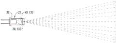
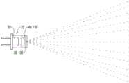
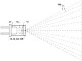
例如,在本发明的一些特定应用中,提供了一种用于口内扫描的装置,该装置包括在远端具有探头的细长的手持棒。在扫描期间,探头可以被配置为进入受试者的口腔内。一个或更多个光投射器(例如,微型结构光投射器)以及一个或更多个摄像头(例如,微型摄像头)结合到设置在探头远端内的刚性结构。每个结构光投射器使用光源(例如激光二极管)发射光。每个光投射器可以被配置为当光源被激活时投射由多个投射器光线限定的光图案。每个摄像头可以被配置为捕获多个图像,这些图像描绘了口内表面上投射的光图案的至少一部分。在一些应用中,结构光投射器可具有至少45度的照射场。可选地,照射场可以小于120度。每个结构光投射器还可以包括图案生成光学元件。图案生成光学元件可以利用衍射和/或折射来生成光图案。在一些应用中,光图案可以是离散的未连接的光点的分布。可选地,当光源(例如,激光二极管)被激活以发射通过图案生成光学元件的光时,光图案在距离图案生成光学元件1mm和30mm之间的所有平面处保持离散的未连接的光点的分布。在一些应用中,每个结构光投射器的图案生成光学元件可以具有至少80%(例如,至少90%)的光通量效率,即落在图案生成器上进入图案的光的比例。每个摄像头包括摄像头传感器和包括一个或更多个透镜的物镜光学器件。For example, in some specific applications of the present invention, a device for intraoral scanning is provided that includes an elongated hand-held wand having a probe at the distal end. During scanning, the probe may be configured to enter the oral cavity of the subject. One or more light projectors (eg, microstructured light projectors) and one or more cameras (eg, microcameras) are incorporated into a rigid structure disposed within the distal end of the probe. Each structured light projector emits light using a light source such as a laser diode. Each light projector may be configured to project a light pattern defined by the plurality of projector rays when the light source is activated. Each camera may be configured to capture a plurality of images depicting at least a portion of the light pattern projected on the intraoral surface. In some applications, a structured light projector may have an illumination field of at least 45 degrees. Alternatively, the irradiation field may be less than 120 degrees. Each structured light projector may also include pattern generating optical elements. Pattern generating optical elements may utilize diffraction and/or refraction to generate patterns of light. In some applications, the light pattern may be a distribution of discrete, unconnected light spots. Optionally, when a light source (e.g., a laser diode) is activated to emit light through the pattern-generating optical element, the light pattern remains discrete unconnected spots of light at all planes between 1 mm and 30 mm from the pattern-generating optical element Distribution. In some applications, the pattern generating optics of each structured light projector may have a flux efficiency, ie, the proportion of light that falls on the pattern generator and enters the pattern, of at least 80% (eg, at least 90%). Each camera includes a camera sensor and objective optics including one or more lenses.
在一些应用中,激光二极管光源和衍射和/或折射图案生成光学元件可以提供某些优点。例如,激光二极管和衍射和/或折射图案生成光学元件的使用可以帮助维持能量有效的结构光投射器,以防止探头在使用期间升温。此外,这些部件可以通过不需要在探头内进行主动冷却来帮助降低成本。例如,现今的激光二极管可以使用小于0.6瓦特的功率,同时以高亮度连续发射(例如与现今的发光二极管(LED)相比)。当根据本发明的一些应用进行脉冲时,这些现今的激光二极管可能使用甚至更少的功率,例如,当以10%的占空比进行脉冲时,激光二极管可以使用小于0.06瓦特(但是对于一些应用,激光二极管可以使用至少0.2瓦特同时以高亮度连续发射,并且当进行脉冲时,可以使用甚至更少的功率,例如,当以10%的占空比进行脉冲时,激光二极管可以使用至少0.02瓦特)。此外,衍射和/或折射图案生成光学元件可以被配置为利用大部分(如果不是全部的话)发射光(例如与阻止一些光线达到对象的掩模相比)。In some applications, laser diode light sources and diffractive and/or refractive pattern generating optics may provide certain advantages. For example, the use of laser diodes and diffractive and/or refractive pattern-generating optics can help maintain an energy-efficient structured light projector to prevent probes from heating up during use. Additionally, these parts can help reduce costs by not requiring active cooling within the probe. For example, today's laser diodes can use less than 0.6 watts of power while emitting continuously at high brightness (compared, for example, to today's light emitting diodes (LEDs)). These present-day laser diodes may use even less power when pulsed according to some applications of the present invention, for example, a laser diode may use less than 0.06 watts when pulsed at a 10% duty cycle (but for some applications , a laser diode can use at least 0.2 watts while continuously emitting at high brightness, and when pulsed, can use even less power, for example, a laser diode can use at least 0.02 watts when pulsed at a 10% duty cycle ). Additionally, diffractive and/or refractive pattern generating optical elements may be configured to utilize most, if not all, of the emitted light (eg, as compared to a mask that blocks some of the light from reaching the object).
特别地,基于衍射和/或折射的图案生成光学元件通过光的衍射、折射或干涉或上述的任何组合生成图案,而不是通过透明或透射掩模进行的光调制。在一些应用中,这可能是有利的,因为光通量(throughput)效率(进入图案的光与落在图案生成器上的光的比例)接近100%(例如,至少80%,例如,至少90%),而与“基于面积的占空比”模式无关。相反,透明掩模或透射掩模图案生成光学元件的光通量效率与“基于面积的占空比”直接相关。例如,对于所需的100:1的“基于面积的占空比”,基于掩模的图案生成器的通过效率将是1%,而基于衍射和/或折射的图案生成光学元件的效率保持接近100%。此外,由于激光器固有地具有较小的发射面积和发散角,导致每单位面积更亮的输出照射,所以激光器的光收集效率比具有相同总光输出的LED高至少10倍。激光器和衍射和/或折射图案生成器的高效率可以帮助实现热效率配置,其限制探头在使用期间显著升温,从而通过潜在地消除或限制探头内的主动冷却的需要来降低成本。虽然在一些应用中激光二极管和DOE可能是特别优选的,但它们单独或组合使用不是必要的。包括LED的其他光源和包括透明和透射掩模的图案生成元件可以在其他应用中使用。In particular, diffraction- and/or refraction-based pattern-generating optical elements generate patterns by diffraction, refraction, or interference of light, or any combination thereof, rather than light modulation through a transparent or transmissive mask. In some applications, this may be advantageous because the throughput efficiency (the ratio of light entering the pattern to light falling on the pattern generator) approaches 100% (e.g., at least 80%, e.g., at least 90%) , regardless of the Area-Based Duty Cycle mode. In contrast, the flux efficiency of transparent mask or transmissive mask pattern generating optics is directly related to the "area-based duty cycle". For example, for a desired "area-based duty cycle" of 100:1, the pass-through efficiency of a mask-based pattern generator would be 1%, while the efficiency of diffractive and/or refraction-based pattern-generating optics remains close to 100%. Furthermore, since lasers inherently have smaller emission areas and divergence angles, resulting in brighter output illumination per unit area, the light collection efficiency of lasers is at least 10 times higher than that of LEDs with the same total light output. The high efficiency of the lasers and diffractive and/or refractive pattern generators can help enable thermally efficient configurations that limit the probe from heating up significantly during use, thereby reducing cost by potentially eliminating or limiting the need for active cooling within the probe. While laser diodes and DOEs may be particularly preferred in some applications, their use alone or in combination is not essential. Other light sources including LEDs and pattern generating elements including transparent and transmissive masks can be used in other applications.
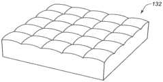
在一些应用中,在不使用诸如用不透明粉末涂覆牙齿等对比度增强方式的情况下,为了改善结构光照射下的口内场景的图像捕获,发明人已经意识到离散的未连接的光点的分布(例如而不是线条)可以在提高图案对比度同时保持有用的信息量之间提供改进的平衡。在一些应用中,未连接的光点具有均匀(例如,不变)的图案。一般而言,更密集的结构光图案可以提供更多的表面采样,更高的分辨率,并且能够更好地拼接从多个图像帧获得的相应表面。然而,结构光图案太密集可能导致更复杂的对应问题,因为存在更多数量的光点要解决对应问题。另外,更密集的结构光图案可能由于系统中更多的光而具有较低的图案对比度,这可能是由(a)杂散光和(b)渗透(percolation)的组合引起的,该杂散光从牙齿的有些光滑的表面反射出来并且可能被摄像头捕捉到,渗透即为一些光进入牙齿,在牙齿内沿多个路径反射,然后在许多不同的方向上离开牙齿。如下文进一步描述的,提供了方法和系统用于解决由离散的未连接的光点的分布所呈现的对应问题。在一些应用中,来自每个投射器的离散的未连接的光点可以是非编码的。In some applications, in order to improve image capture of intraoral scenes illuminated by structured light without the use of contrast-enhancing means such as coating teeth with opaque powders, the inventors have realized the distribution of discrete unconnected points of light (instead of lines, for example) may provide an improved balance between increasing pattern contrast while maintaining a useful amount of information. In some applications, the unconnected spots have a uniform (eg, constant) pattern. In general, denser structured light patterns provide more surface sampling, higher resolution, and enable better stitching of corresponding surfaces obtained from multiple image frames. However, a structured light pattern that is too dense may lead to a more complex correspondence problem, since there are a greater number of light points to solve the correspondence problem. Additionally, denser structured light patterns may have lower pattern contrast due to more light in the system, which may be caused by a combination of (a) stray light and (b) percolation from The somewhat smooth surface of the tooth reflects off and may be captured by a camera, penetration is where some light enters the tooth, reflects along multiple paths within the tooth, and then exits the tooth in many different directions. As described further below, methods and systems are provided for addressing the corresponding problems presented by the distribution of discrete unconnected spots. In some applications, the discrete unconnected spots of light from each projector may be non-coded.
在一些应用中,每个摄像头的视场可以是至少45度,例如,至少80度(例如85度)。可选地,每个摄像头的视场可以小于120度,例如小于90度。对于一些应用,一个或更多个摄像头具有鱼眼透镜或提供高达180度视角(viewing)的其他光学器件。In some applications, each camera may have a field of view of at least 45 degrees, eg, at least 80 degrees (eg, 85 degrees). Optionally, the field of view of each camera may be less than 120 degrees, such as less than 90 degrees. For some applications, one or more cameras have fisheye lenses or other optics that provide viewing up to 180 degrees.
在任何情况下,各种摄像头的视场可以相同或不同。类似地,各种摄像头的焦距可以相同或不同。本文使用的每个摄像头的术语“视场”指的是每个摄像头的对角视场。此外,每个摄像头可以被配置为聚焦在距离与相应的摄像头传感器相距最远的透镜1mm到30mm之间,例如,至少5mm和/或小于11mm,例如9mm-10mm的对象焦平面处。类似地,在一些应用中,每个结构光投射器的照射场可以是至少45度并且可选地小于120度。发明人已经认识到,通过组合所有摄像头的各个视场而实现的大视场由于减少的图像拼接错误量可以提高准确度,尤其是在无牙区域中,其中牙龈表面光滑并且可能存在更少的清晰的高分辨率三维特征。具有更大的视场使得诸如牙齿的整体曲线等大的光滑特征能够出现在每个图像帧中,这提高了拼接从多个这样的图像帧获得的各个表面的精度。在一些应用中,各种摄像头(例如,口内扫描仪)的整个组合的视场沿细长手持棒的纵轴在约20mm和约50mm之间,并且沿z轴约20-40mm,其中z轴可以对应于深度。在其他应用中,视场沿纵轴可以是至少20mm、至少25mm、至少30mm、至少35mm或至少40mm。在一些实施例中,组合的视场可随深度(例如,随扫描距离)而变化。例如,在大约4mm的扫描距离处,视场沿纵轴可以是大约40mm,在大约14mm的扫描距离处,视场沿纵轴可以是大约45mm。如果口内扫描仪的大部分运动是相对于扫描仪的长轴(例如,纵轴)完成,则扫描之间的重叠可能是大量的。在一些应用中,组合的摄像头的视场不连续。例如,口内扫描仪可以具有以固定间隔与第二视场分离的第一视场。固定间隔可以例如沿细长手持棒的纵轴。In any case, the fields of view of the various cameras may be the same or different. Similarly, the focal lengths of the various cameras may be the same or different. The term "field of view" for each camera used herein refers to the diagonal field of view of each camera. Furthermore, each camera may be configured to focus at an object focal plane between 1 mm and 30 mm, eg, at least 5 mm and/or less than 11 mm, eg 9 mm-10 mm, from the lens furthest from the respective camera sensor. Similarly, in some applications, the illumination field of each structured light projector may be at least 45 degrees and optionally less than 120 degrees. The inventors have realized that the large field of view achieved by combining the individual fields of view of all cameras can improve accuracy due to the reduced amount of image stitching errors, especially in edentulous areas where the gingival surface is smooth and there may be fewer Clear high-resolution 3D features. Having a larger field of view enables large smooth features such as the overall curve of a tooth to appear in each image frame, which improves the accuracy of stitching individual surfaces obtained from multiple such image frames. In some applications, the entire combined field of view of the various cameras (e.g., an intraoral scanner) is between about 20 mm and about 50 mm along the longitudinal axis of the elongated hand-held wand, and about 20-40 mm along the z-axis, where the z-axis can corresponds to the depth. In other applications, the field of view may be at least 20 mm, at least 25 mm, at least 30 mm, at least 35 mm, or at least 40 mm along the longitudinal axis. In some embodiments, the combined field of view may vary with depth (eg, with scan distance). For example, at a scan distance of about 4 mm, the field of view may be about 40 mm along the longitudinal axis, and at a scan distance of about 14 mm, the field of view may be about 45 mm along the longitudinal axis. If most of the movement of the intraoral scanner is done relative to the long axis (eg, longitudinal axis) of the scanner, the overlap between scans may be substantial. In some applications, the fields of view of the combined cameras are discontinuous. For example, an intraoral scanner may have a first field of view separated from a second field of view at a fixed interval. The fixed spacing may for example be along the longitudinal axis of the elongated hand stick.
在一些应用中,提供了一种方法,用于生成口内表面的数字三维图像。应注意,作为在本申请中使用的短语的“三维图像”是基于三维模型(例如点云),从该三维模型构建三维口内表面的图像。所得到的图像虽然通常显示在二维屏幕上,但是包含与被扫描对象的三维结构有关的数据,因此通常可以被操纵以便从不同的视图和视角显示被扫描的对象。另外,可以使用来自三维图像的数据来制作被扫描对象的物理三维模型。In some applications, a method is provided for generating a digital three-dimensional image of an intraoral surface. It should be noted that "three-dimensional image" as the phrase used in this application is based on a three-dimensional model (such as a point cloud) from which an image of a three-dimensional intraoral surface is constructed. The resulting images, although typically displayed on a two-dimensional screen, contain data relating to the three-dimensional structure of the scanned object and can therefore often be manipulated to display the scanned object from different views and perspectives. Additionally, data from the three-dimensional images can be used to make a physical three-dimensional model of the scanned object.
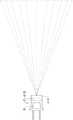
例如,可以驱动一个或更多个结构光投射器以在口内表面上投射离散的未连接的光点的分布,并且可以驱动一个或更多个摄像头以捕获投射的图像。由每个摄像头捕获的图像可以包括至少一个光点。For example, one or more structured light projectors may be driven to project a distribution of discrete unconnected spots of light on the intraoral surface, and one or more cameras may be driven to capture the projected images. Images captured by each camera may include at least one light spot.
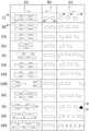
每个摄像头包括具有像素阵列的摄像头传感器,对于每个像素,在三维空间中存在源自该像素的相应光线,该光线的方向朝向被成像的对象;当在传感器上成像时,沿这些光线中的特定的一个的每个点将落在传感器上其对应的相应像素上。如在本申请全文中所使用的,包括在权利要求中,用于此的术语是“摄像头光线”。类似地,对于来自每个投射器的每个投射光点,存在相应的投射器光线。每个投射器光线对应于至少一个摄像头传感器上的相应的像素路径,即,如果摄像头看到由特定投射器光线投射的光点,则该光点必须由与该特定投射器光线对应的像素的特定路径上的像素检测。(a)与每个摄像头的摄像头传感器上的每个像素相对应的摄像头光线的值以及(b)与来自每个投射器的每个投射的光点相对应的投射器光线的值可以在校准过程期间存储,如下所述。Each camera includes a camera sensor with an array of pixels, and for each pixel there is a corresponding ray originating from that pixel in three-dimensional space, directed towards the object being imaged; when imaging on the sensor, along these rays Each point of a particular one will fall on its corresponding corresponding pixel on the sensor. As used throughout this application, including in the claims, the term used for this is "camera light". Similarly, for each projected spot from each projector, there is a corresponding projector ray. Each projector ray corresponds to a corresponding pixel path on at least one camera sensor, i.e., if a camera sees a spot cast by a particular projector ray, that spot must be represented by the pixel corresponding to that particular projector ray. Pixel detection on a specific path. The value of (a) the camera ray corresponding to each pixel on the camera sensor of each camera and (b) the value of the projector ray corresponding to each projected light point from each projector can be obtained in the calibration Stored during the process, as described below.
基于存储的校准值,处理器可以用于运行对应算法,以识别表面上每个投射光点的三维位置。对于给定的投射器光线,处理器“查看”其中一个摄像头上的相应摄像头传感器路径。沿该摄像头传感器路径的每个检测的光点将具有与给定投射器光线交叉的摄像头光线。该交叉点定义了空间中的三维点。然后,处理器在其他摄像头上的与给定投射器光线相对应的摄像头传感器路径中进行搜索,并识别有多少其他摄像头在它们的与给定投射器光线对应的相应摄像头传感器路径上还检测到光点,该光点的摄像头光线在空间中与三维点相交。如本申请全文所使用的,如果两个或更多个摄像头检测到其相应的摄像头光线与给定投射器光线在空间中的相同三维点处相交的光点,则认为摄像头“同意”该光点位于该三维点处。因此,处理器可以基于两个或更多个摄像头同意在特定交叉点处存在投射器光线投射的光图案来识别投射的光图案的三维位置。沿摄像头传感器路径对额外的光点重复该过程,并且将摄像头“同意”的最大数量的光点识别为从给定投射器光线投射到表面上的光点。因此,针对该光点计算表面上的三维位置。Based on the stored calibration values, the processor can be used to run a corresponding algorithm to identify the three-dimensional position of each projected point of light on the surface. For a given projector ray, the processor "looks" at the corresponding camera sensor path on one of the cameras. Each detected light point along this camera sensor path will have a camera ray that intersects a given projector ray. This intersection defines a three-dimensional point in space. The processor then searches through the camera sensor paths on the other cameras corresponding to the given projector ray and identifies how many other cameras also detect The point of light for which the camera ray intersects the 3D point in space. As used throughout this application, cameras are considered to "agree" if two or more cameras detect a point where their corresponding camera ray intersects a given projector ray at the same three-dimensional point in space. A point is located at this three-dimensional point. Accordingly, the processor may identify the three-dimensional location of the projected light pattern based on the two or more cameras agreeing that there is a light pattern cast by the projector ray at a particular intersection point. The process is repeated for additional blips along the camera sensor path, and the maximum number of blips that the camera "agrees to" is identified as blips cast from a given projector ray onto the surface. Thus, a three-dimensional position on the surface is calculated for this point of light.
一旦确定了特定光点在表面上的位置,则可以不考虑投射该光点的投射器光线以及与该光点相对应的所有摄像头光线,并且可以对下一个投射器光线再次运行对应算法。最终,识别的三维位置可以用于生成口内表面的数字三维模型。Once the position of a particular point of light on the surface is determined, the projector ray that cast that point and all camera rays corresponding to that point can be disregarded, and the corresponding algorithm can be run again for the next projector ray. Ultimately, the identified 3D locations can be used to generate a digital 3D model of the intraoral surfaces.
在另一示例中,生成口内表面的数字三维模型的方法可以包括使用设置在口内扫描仪远端的探头中的一个或更多个光投射器将离散的未连接的光点的图案投射到患者的口内表面上,其中离散的未连接的光点的图案是非编码的。该方法还可以包括使用设置在探头中的两个或更多个摄像头捕获未连接的光点的投射的图案的多个图像,解码投射的图案的多个图像以便确定口内表面的三维表面信息,并且使用三维表面信息生成口内表面的数字三维模型。解码多个图像可以包括访问将对应于两个或更多个摄像头的每一个的摄像头传感器上的像素的摄像头光线与多个投射器光线相关联的校准数据,其中多个投射器光线的每一个与其中一个离散的未连接的光点相关联。解码还可以包括使用校准数据确定投射器光线和对应于投射的离散的未连接的光点的图案的摄像头光线的交叉点,其中投射器光线和摄像头光线的交叉点与空间中的三维点相关联。解码还可以包括基于两个或更多个摄像头同意在特定交叉点处存在投射器光线投射的离散的未连接的光点来识别离散的未连接的光点的图案的三维位置。In another example, a method of generating a digital three-dimensional model of an intraoral surface may include projecting a pattern of discrete unconnected points of light onto a patient using one or more light projectors disposed in a probe distal to an intraoral scanner. On the intraoral surface, the pattern of discrete unconnected spots is non-encoded. The method may further comprise capturing a plurality of images of the projected pattern of unconnected points of light using two or more cameras disposed in the probe, decoding the plurality of images of the projected pattern to determine three-dimensional surface information of the intraoral surface, And a digital three-dimensional model of the intraoral surface is generated using the three-dimensional surface information. Decoding the plurality of images may include accessing calibration data that correlates camera rays corresponding to pixels on the camera sensor of each of the two or more cameras with a plurality of projector rays, where each of the plurality of projector rays Associated with one of the discrete unconnected blips. Decoding may also include using the calibration data to determine an intersection of a projector ray and a camera ray corresponding to the projected pattern of discrete unconnected points of light, wherein the intersection of the projector ray and the camera ray is associated with a three-dimensional point in space . Decoding may also include identifying a three-dimensional position of a pattern of discrete unconnected points of light based on the two or more cameras agreeing that there are discrete unconnected points of light cast by the projector raycast at a particular intersection point.
因此,根据本发明的一些应用,提供了用于口内扫描的装置,该装置包括:Thus, according to some applications of the present invention, there is provided an apparatus for intraoral scanning comprising:
细长的手持棒,包括在手持棒的远端处的探头;An elongated hand-held wand including a probe at the distal end of the hand-held wand;
刚性结构,设置在探头远端内;a rigid structure arranged in the distal end of the probe;
一个或更多个结构光投射器,结合到刚性结构;以及one or more structured light projectors coupled to the rigid structure; and
一个或更多个摄像头,结合到刚性结构。One or more cameras, bonded to a rigid structure.
在一些应用中,每个结构光投射器可以具有45-120度的照射场。可选地,一个或更多个结构光投射器可以使用激光二极管光源。此外,结构光投射器可以包括光束整形光学元件。此外,结构光投射器可以包括图案生成光学元件。In some applications, each structured light projector may have an illumination field of 45-120 degrees. Alternatively, one or more structured light projectors may use a laser diode light source. Furthermore, the structured light projector may include beam shaping optics. Furthermore, the structured light projector may comprise pattern generating optical elements.
图案生成光学元件可以被配置为生成离散的未连接的光点的分布。当光源(例如,激光二极管)被激活以发射通过图案生成光学元件的光时,在距离图案生成光学元件1mm和30mm之间的所有平面处可以生成离散的未连接的光点的分布。在一些应用中,图案生成光学元件(i)利用衍射和/或折射来生成该分布。可选地,图案生成光学元件具有至少90%的光通量效率。The pattern generating optical element may be configured to generate a distribution of discrete unconnected spots. When a light source (eg a laser diode) is activated to emit light through the pattern-generating optical element, a distribution of discrete unconnected light spots can be generated at all planes between 1 mm and 30 mm from the pattern-generating optical element. In some applications, the pattern generating optical element (i) utilizes diffraction and/or refraction to generate this distribution. Optionally, the pattern generating optical element has a flux efficiency of at least 90%.
此外,在一些应用中,每个摄像头可以(a)具有45-120度的视场。摄像头可以包括摄像头传感器和包括一个或更多个透镜的物镜光学器件。在一些应用中,摄像头可以被配置为聚焦在距离与摄像头传感器相距最远的透镜1mm和30mm之间的对象焦平面处。Additionally, in some applications, each camera may (a) have a 45-120 degree field of view. A camera may include a camera sensor and objective optics including one or more lenses. In some applications, the camera may be configured to focus on an object focal plane between 1 mm and 30 mm from the lens furthest from the camera sensor.
对于一些应用,一个或更多个摄像头中的每一个被配置为聚焦在距离与摄像头传感器相距最远的透镜5mm和11mm之间的对象焦平面处。For some applications, each of the one or more cameras is configured to focus at an object focal plane between 5 mm and 11 mm from the lens furthest from the camera sensor.
对于一些应用,一个或更多个投射器中的每一个的图案生成光学元件被配置为当光源(例如,激光二极管)被激活以发射通过图案生成光学元件的光时,在距离图案生成光学元件4mm和24mm之间的所有平面处生成离散的未连接的光点的分布。For some applications, the pattern-generating optical element of each of the one or more projectors is configured such that when a light source (eg, a laser diode) is activated to emit light through the pattern-generating optical element, at a distance from the pattern-generating optical element A distribution of discrete unconnected spots is generated at all planes between 4mm and 24mm.
对于一些应用,一个或更多个摄像头中的每一个被配置为聚焦在距离与摄像头传感器相距最远的透镜4mm和24mm之间的对象焦平面处。For some applications, each of the one or more cameras is configured to focus at an object focal plane between 4 mm and 24 mm from the lens furthest from the camera sensor.
对于一些应用,每个结构光投射器具有70-100度的照射场。For some applications, each structured light projector has an illumination field of 70-100 degrees.
对于一些应用,每个摄像头具有70-100度的视场。For some applications, each camera has a field of view of 70-100 degrees.
对于一些应用,每个摄像头具有80-90度的视场。For some applications, each camera has an 80-90 degree field of view.
对于一些应用,该装置还包括至少一个均匀光投射器,被配置为将白光投射到被扫描的对象上,并且至少一个摄像头被配置为使用来自均匀光投射器的照射来捕获对象的二维彩色图像。For some applications, the apparatus also includes at least one uniform light projector configured to project white light onto the object being scanned, and at least one camera configured to capture a two-dimensional color image of the object using illumination from the uniform light projector. image.
对于一些应用,光束整形光学元件包括准直透镜。For some applications, the beam shaping optics include collimating lenses.
对于一些应用,结构光投射器和摄像头被定位成使得每个结构光投射器面向放置在其照射场中的棒(wand)外部的对象。可选地,每个摄像头可以面向放置在其视场中的棒外部的对象。此外,在一些应用中,至少20%的离散的未连接的光点位于至少一个摄像头的视场中。For some applications, the structured light projectors and cameras are positioned such that each structured light projector faces an object placed outside the wand in its illuminated field. Optionally, each camera can be oriented towards objects placed outside the wand in its field of view. Additionally, in some applications, at least 20% of the discrete unconnected points of light are located within the field of view of at least one camera.
对于一些应用,探头的高度为10-15mm,其中光通过探头的下表面(或感应表面)进入探头,并且从探头的下表面到与下表面相对的探头的上表面测量探头的高度。For some applications, the height of the probe is 10-15 mm, where light enters the probe through the lower surface (or sensing surface) of the probe, and the height of the probe is measured from the lower surface of the probe to the upper surface of the probe opposite the lower surface.
对于一些应用,一个或更多个结构光投射器恰好是一个结构光投射器,并且一个或更多个摄像头恰好是一个摄像头。For some applications, the one or more structured light projectors are exactly one structured light projector, and the one or more cameras are exactly one camera.
对于一些应用,图案生成光学元件包括衍射光学元件(DOE)。For some applications, the pattern generating optical element includes a diffractive optical element (DOE).
对于一些应用,每个DOE被配置为生成离散的未连接的光点的分布,使得当光源被激活以发射通过DOE的光时,对于照射场中的每个正交平面,照射面积与非照射面积的比率是1:150-1:16。For some applications, each DOE is configured to generate a distribution of discrete unconnected points of light such that when the light source is activated to emit light through the DOE, for each orthogonal plane in the illuminated field, the illuminated area differs from the non-illuminated The ratio of the area is 1:150-1:16.
对于一些应用,每个DOE被配置为生成离散的未连接的光点的分布,使得当光源被激活以发射通过DOE的光时,对于照射场中的每个正交平面,照射面积与非照射面积的比率是1:64-1:36。For some applications, each DOE is configured to generate a distribution of discrete unconnected points of light such that when the light source is activated to emit light through the DOE, for each orthogonal plane in the illuminated field, the illuminated area differs from the non-illuminated The ratio of the area is 1:64-1:36.
对于一些应用,一个或更多个结构光投射器是多个结构光投射器。在一些应用中,特定DOE生成的每个光点都具有相同的形状。可选地,由至少一个DOE生成的光点的形状不同于由至少一个其他DOE生成的光点的形状。For some applications, the one or more structured light projectors is a plurality of structured light projectors. In some applications, each spot generated by a particular DOE has the same shape. Optionally, the shape of the spot generated by at least one DOE is different from the shape of the spot generated by at least one other DOE.
对于一些应用,一个或更多个投射器的每一个包括设置在光束整形光学元件和DOE之间的光学元件,该光学元件被配置为当激光二极管被激活以发射通过光学元件的光时生成贝塞尔(Bessel)光束,使得离散的未连接的光点通过以DOE为中心并且半径在1mm和30mm之间的球体的每个内表面保持小于0.06mm的直径。For some applications, each of the one or more projectors includes an optical element disposed between the beam-shaping optic and the DOE, the optical element being configured to generate a Beam beam when the laser diode is activated to emit light through the optical element. Bessel beams such that discrete unconnected spots remain less than 0.06 mm in diameter through each inner surface of a sphere centered on the DOE and having a radius between 1 mm and 30 mm.
对于一些应用,光学元件被配置为当激光二极管被激活以发射通过光学元件的光时生成贝塞尔(Bessel)光束,使得离散的未连接的光点通过以DOE为中心并且半径在1mm和30mm之间的几何球的每个内表面保持小于0.02mm的直径。For some applications, the optical element is configured to generate a Bessel beam when the laser diode is activated to emit light through the optical element such that discrete unconnected spots of light pass through the DOE with radii between 1mm and 30mm Each inner surface of the geometric spheres in between maintains a diameter of less than 0.02mm.
对于一些应用,一个或更多个投射器中的每一个包括设置在光束整形光学元件和DOE之间的光学元件。光学元件可以被配置为当光源被激活以发射通过光学元件的光时生成贝塞尔(Bessel)光束,使得离散的未连接的光点在整个深度范围内保持小直径。例如,在一些应用中,离散的未连接的光点可以通过距离DOE在1mm和30mm之间的每个正交平面保持小于0.06mm的直径。For some applications, each of the one or more projectors includes optics disposed between the beam shaping optics and the DOE. The optical element may be configured to generate a Bessel beam when the light source is activated to emit light through the optical element such that discrete unconnected spots of light remain small in diameter throughout the depth range. For example, in some applications, discrete unconnected spots may maintain a diameter of less than 0.06 mm through each orthogonal plane at a distance of between 1 mm and 30 mm from the DOE.
对于一些应用,光学元件被配置为当激光二极管被激活以发射通过光学元件的光时生成贝塞尔(Bessel)光束,使得离散的未连接的光点通过距离DOE在1mm和30mm之间的每个正交平面保持小于0.02mm的直径。For some applications, the optical element is configured to generate a Bessel beam when the laser diode is activated to emit light through the optical element, such that discrete unconnected spots of light pass through every distance DOE between 1 mm and 30 mm. An orthogonal plane remains less than 0.02mm in diameter.
对于一些应用,光学元件被配置为当激光二极管被激活以发射通过光学元件的光时生成贝塞尔(Bessel)光束,使得离散的未连接的光点通过距离DOE在4mm和24mm之间的每个正交平面保持小于0.04mm的直径。For some applications, the optical element is configured to generate a Bessel beam when the laser diode is activated to emit light through the optical element, such that discrete unconnected spots of light pass each distance DOE between 4 mm and 24 mm. An orthogonal plane remains less than 0.04mm in diameter.
对于一些应用,光学元件是轴锥透镜。For some applications, the optical element is an axicon.
对于一些应用,轴锥透镜是衍射轴锥透镜。For some applications, the axicon is a diffractive axicon.
对于一些应用,光学元件是环形光圈。For some applications, the optical element is an annular aperture.
对于一些应用,一个或更多个结构光投射器是多个结构光投射器,并且至少两个结构光投射器的光源被配置为分别发射两个不同波长的光。For some applications, the one or more structured light projectors are a plurality of structured light projectors, and the light sources of at least two structured light projectors are configured to respectively emit light at two different wavelengths.
对于一些应用,至少三个结构光投射器的光源被配置为分别发射三个不同波长的光。For some applications, the light sources of at least three structured light projectors are configured to respectively emit light of three different wavelengths.
对于一些应用,至少三个结构光投射器的光源被配置为分别发射红光、蓝光和绿光。For some applications, the light sources of at least three structured light projectors are configured to emit red, blue, and green light, respectively.
在一些应用中,光源包括激光二极管。In some applications, the light source includes a laser diode.
对于一些应用,一个或更多个摄像头是结合到刚性结构的多个摄像头,使得至少两个摄像头的两个相应光轴之间的角度是0-90度。For some applications, the one or more cameras are multiple cameras bonded to a rigid structure such that the angle between two corresponding optical axes of at least two cameras is 0-90 degrees.
对于一些应用,至少两个摄像头的两个相应光轴之间的角度是0-35度。For some applications, the angle between two corresponding optical axes of at least two cameras is 0-35 degrees.
对于一些应用,一个或更多个结构光投射器是结合到刚性结构的多个结构光投射器,使得至少两个结构光投射器的两个相应光轴之间的角度为0-90度。For some applications, the one or more structured light projectors are a plurality of structured light projectors bonded to a rigid structure such that the angle between two respective optical axes of at least two structured light projectors is 0-90 degrees.
对于一些应用,至少两个结构光投射器的两个相应光轴之间的角度是0-35度。For some applications, the angle between two respective optical axes of at least two structured light projectors is 0-35 degrees.
对于一些应用,每个摄像头具有多个离散的预设焦点位置,在每个焦点位置处,摄像头被配置为聚焦在相应的对象焦平面处。For some applications, each camera has a plurality of discrete preset focus positions at which the camera is configured to focus at a corresponding object focal plane.
对于一些应用,每个摄像头包括自动聚焦致动器,被配置为从离散的预设焦点位置选择焦点位置。For some applications, each camera includes an autofocus actuator configured to select a focus position from discrete preset focus positions.
对于一些应用,一个或更多个摄像头中的每一个包括光学光圈相位掩模,被配置为延伸摄像头的焦深(depth of focus),使得由每个摄像头形成的图像在距离与摄像头传感器相距最远的透镜1mm和30mm之间的所有物距上保持聚焦。For some applications, each of the one or more cameras includes an optical aperture phase mask configured to extend the depth of focus of the cameras such that images formed by each camera are The far lens remains in focus at all object distances between 1mm and 30mm.
对于一些应用,光学光圈相位掩模被配置为延伸摄像头的焦深,使得由每个摄像头形成的图像在距离与摄像头传感器相距最远的透镜4mm和24mm之间的所有物距上保持聚焦。For some applications, the optical aperture phase mask is configured to extend the depth of focus of the cameras so that the image formed by each camera remains in focus at all object distances between 4mm and 24mm from the lens furthest from the camera sensor.
对于一些应用,一个或更多个摄像头中的每一个被配置为以每秒30-200帧的帧速率捕获图像。For some applications, each of the one or more cameras is configured to capture images at a frame rate of 30-200 frames per second.
对于一些应用,一个或更多个摄像头中的每一个被配置为以至少每秒75帧的帧速率捕获图像。For some applications, each of the one or more cameras is configured to capture images at a frame rate of at least 75 frames per second.
对于一些应用,一个或更多个摄像头中的每一个被配置为以至少每秒100帧的帧速率捕获图像。For some applications, each of the one or more cameras is configured to capture images at a frame rate of at least 100 frames per second.
对于一些应用,一个或更多个投射器的每一个的激光二极管被配置为发射椭圆形光束。一个或更多个投射器的每一个的光束整形光学元件可以包括准直透镜。可选地,图案生成光学元件包括衍射光学元件(DOE),其被分割成布置为阵列的多个子DOE片。每个子DOE片可以在照射场的不同区域中生成离散的未连接的光点的相应分布,使得当光源被激活以发射通过分割的DOE的光时生成离散的未连接的光点的分布。For some applications, the laser diode of each of the one or more projectors is configured to emit an elliptical beam. The beam shaping optics of each of the one or more projectors may include a collimating lens. Optionally, the pattern generating optical element comprises a diffractive optical element (DOE) segmented into a plurality of sub-DOE slices arranged in an array. Each sub-DOE slice may generate a respective distribution of discrete unconnected spots in a different region of the illumination field such that a distribution of discrete unconnected spots is generated when the light source is activated to emit light through the segmented DOE.
对于一些应用,准直透镜可以被配置为生成长轴为500-700微米、短轴为100-200微米的椭圆光束。For some applications, the collimating lens may be configured to generate an elliptical beam with a major axis of 500-700 microns and a minor axis of 100-200 microns.
对于一些应用,当激光二极管被激活以发射通过分割的DOE的光时,子DOE片阵列可以被定位成包含在椭圆形光束内。For some applications, an array of sub-DOE slices may be positioned to be contained within an elliptical beam when a laser diode is activated to emit light through a segmented DOE.
对于一些应用,每个子DOE片的横截面是具有30-75微米长度的边的正方形,且横截面垂直于DOE的光轴。For some applications, the cross-section of each sub-DOE sheet is a square with sides 30-75 microns in length, and the cross-section is perpendicular to the optical axis of the DOE.
对于一些应用,多个子DOE片被布置成矩形阵列,包括16-72个子DOE片并且具有500-800微米的最长尺寸。For some applications, multiple sub-DOE-sheets are arranged in a rectangular array comprising 16-72 sub-DOE-sheets and having a longest dimension of 500-800 microns.
对于一些应用,准直透镜和分割的DOE是单个光学元件,光学元件的第一侧包括准直透镜,以及与第一侧相对的光学元件的第二侧包括分割的DOE。For some applications, the collimating lens and the segmented DOE are a single optical element, a first side of the optical element includes the collimating lens, and a second side of the optical element opposite the first side includes the segmented DOE.
对于一些应用,一个或更多个投射器的每一个的至少一个光源是多个激光二极管。在一些应用中,多个激光二极管可以被配置为发射相同波长的光。For some applications, the at least one light source of each of the one or more projectors is a plurality of laser diodes. In some applications, multiple laser diodes may be configured to emit light at the same wavelength.
对于一些应用,多个激光二极管可以被配置为发射不同波长的光。For some applications, multiple laser diodes may be configured to emit light at different wavelengths.
对于一些应用,多个激光二极管是两个激光二极管,两个激光二极管被配置为分别发射两个不同波长的光。For some applications, the plurality of laser diodes is two laser diodes configured to respectively emit light at two different wavelengths.
对于一些应用,多个激光二极管是三个激光二极管,三个激光二极管被配置为分别发射三个不同波长的光。For some applications, the plurality of laser diodes is three laser diodes configured to respectively emit light at three different wavelengths.
对于一些应用,三个激光二极管被配置为分别发射红光、蓝光和绿光。For some applications, three laser diodes are configured to emit red, blue, and green light, respectively.
对于一些应用:For some applications:
一个或更多个投射器的每一个的光束整形光学元件包括准直透镜,以及the beam shaping optics of each of the one or more projectors include a collimating lens, and
图案生成光学元件包括具有100-400nm的周期结构特征尺寸的复合衍射周期结构。The pattern generating optical element comprises a composite diffractive periodic structure with a periodic structure feature size of 100-400 nm.
对于一些应用,准直透镜和复合衍射周期结构是单个光学元件,光学元件的第一侧包括准直透镜,以及与第一侧相对的光学元件的第二侧包括复合衍射周期结构。For some applications, the collimating lens and the compound diffractive periodic structure are a single optical element, a first side of the optical element includes the collimating lens, and a second side of the optical element opposite the first side includes the compound diffractive periodic structure.
对于一些应用,该装置还包括设置在准直透镜和复合衍射周期结构之间的轴锥透镜,该轴锥透镜具有0.2-2度的轴锥头角。For some applications, the device further includes an axicon lens disposed between the collimator lens and the compound diffractive periodic structure, the axicon lens having an axicon head angle of 0.2-2 degrees.
对于一些应用,准直透镜具有1.2-2mm的焦距。For some applications, the collimating lens has a focal length of 1.2-2mm.
对于一些应用:For some applications:
一个或更多个投射器的每一个的光束整形光学元件包括准直透镜,以及the beam shaping optics of each of the one or more projectors include a collimating lens, and
图案生成光学元件包括具有0.2-0.7的数值孔径的微透镜阵列。The pattern generating optics comprise a microlens array with a numerical aperture of 0.2-0.7.
对于一些应用,微透镜阵列是六边形微透镜阵列。For some applications, the microlens array is a hexagonal microlens array.
对于一些应用,微透镜阵列是矩形微透镜阵列。For some applications, the microlens array is a rectangular microlens array.
对于一些应用,准直透镜和微透镜阵列是单个光学元件,光学元件的第一侧包括准直透镜,以及与第一侧相对的光学元件的第二侧包括微透镜阵列。For some applications, the collimating lens and the microlens array are a single optical element, a first side of the optical element includes the collimating lens, and a second side of the optical element, opposite the first side, includes the microlens array.
对于一些应用,该装置还包括设置在准直透镜和微透镜阵列之间的轴锥透镜,该轴锥透镜具有0.2-2度的轴锥头角。For some applications, the device further includes an axicon lens disposed between the collimator lens and the microlens array, the axicon lens having an axicon head angle of 0.2-2 degrees.
对于一些应用,准直透镜具有1.2-2mm的焦距。For some applications, the collimating lens has a focal length of 1.2-2 mm.
对于一些应用:For some applications:
一个或更多个投射器的每一个的光束整形光学元件包括准直透镜,该准直透镜具有1.2-2mm的焦距,The beam shaping optics of each of the one or more projectors comprise a collimating lens having a focal length of 1.2-2 mm,
一个或更多个投射器中的每一个包括设置在准直透镜和图案生成光学元件之间的光圈环,以及Each of the one or more projectors includes an aperture ring disposed between the collimating lens and the pattern generating optics, and
图案生成光学元件包括具有100-400nm的周期结构特征尺寸的复合衍射周期结构。The pattern generating optical element comprises a composite diffractive periodic structure with a periodic structure feature size of 100-400 nm.
对于一些应用:For some applications:
一个或更多个投射器的每一个的光束整形光学元件包括透镜,该透镜(a)设置在激光二极管和图案生成光学元件之间,并且(b)在透镜的第一侧上具有平面表面并在与第一侧相对的透镜的第二侧上具有非球面表面,该非球面表面被配置为当激光二极管被激活以发射通过透镜和图案生成光学元件的发散光束时,直接从发散光束生成贝塞尔光束,使得离散的未连接的光点在距图案生成光学元件1mm和30mm之间的任何正交平面处具有基本均匀的尺寸。The beam shaping optics of each of the one or more projectors include a lens (a) disposed between the laser diode and the pattern generating optics, and (b) having a planar surface on a first side of the lens and On a second side of the lens, opposite the first side, there is an aspheric surface configured to generate a bezel directly from the diverging beam when the laser diode is activated to emit the diverging beam through the lens and the pattern generating optical element. Searle beams such that discrete unconnected spots are of substantially uniform size at any orthogonal plane between 1 mm and 30 mm from the pattern generating optical element.
对于一些应用,透镜的非球面表面被配置为当激光二极管被激活以发射通过透镜和图案生成光学元件的发散光束时,直接从发散光束生成贝塞尔光束,使得离散的未连接的光点在距图案生成光学元件4mm和24mm之间的任何正交平面处具有基本均匀的尺寸。For some applications, the aspheric surface of the lens is configured to generate a Bessel beam directly from the diverging beam when the laser diode is activated to emit the diverging beam through the lens and pattern generating optics, such that discrete unconnected spots in Have substantially uniform dimensions at any orthogonal plane between 4mm and 24mm from the pattern generating optical element.
对于一些应用,图案生成光学元件包括具有100-400nm的周期结构特征尺寸的复合衍射周期结构。For some applications, the pattern generating optical element includes a composite diffractive periodic structure with a periodic structure feature size of 100-400 nm.
对于一些应用,图案生成光学元件包括具有0.2-0.7数值孔径的微透镜阵列。For some applications, the pattern generating optical element includes a microlens array with a numerical aperture of 0.2-0.7.
对于一些应用:For some applications:
(a)光束整形光学元件包括在透镜的第一侧上的非球面表面,和(b)在与第一侧相对的透镜的第二侧上的平面表面被成形为限定图案生成光学元件,以及(a) the beam shaping optical element comprises an aspheric surface on a first side of the lens, and (b) a planar surface on a second side of the lens opposite the first side is shaped to define the pattern generating optical element, and
非球面表面被配置为当激光二极管被激活以发射通过透镜的发散光束时,直接从发散光束生成贝塞尔光束,使得当激光二极管被激活以发射通过透镜的发散光束时贝塞尔光束被分成离散的贝塞尔光束阵列,使得离散的未连接的光点在距透镜1mm和30mm之间的所有平面处具有基本均匀的尺寸。The aspheric surface is configured to generate a Bessel beam directly from the diverging beam when the laser diode is activated to emit the diverging beam through the lens such that the Bessel beam is split into Discrete Bessel beam array such that discrete unconnected spots are of substantially uniform size in all planes between 1mm and 30mm from the lens.
对于一些应用,透镜的平面表面被成形为限定图案生成光学元件,使得当激光二极管被激活以发射通过透镜的发散光束时贝塞尔光束被分成离散的贝塞尔光束阵列,使得离散的未连接的光点在距图案生成光学元件4mm和24mm之间的所有平面处具有基本均匀的尺寸。For some applications, the planar surface of the lens is shaped to define a pattern-generating optical element such that when a laser diode is activated to emit a diverging beam through the lens, the Bessel beam is split into an array of discrete Bessel beams such that the discrete unconnected The spot of light has a substantially uniform size at all planes between 4 mm and 24 mm from the pattern generating optical element.
对于一些应用,该装置和方法还可以包括:For some applications, the apparatus and method may also include:
至少一个温度传感器,结合到刚性结构并被配置为测量刚性结构的温度;以及at least one temperature sensor coupled to the rigid structure and configured to measure the temperature of the rigid structure; and
温度控制单元。Temperature control unit.
温度控制电路可以被配置为(a)从温度传感器接收指示刚性结构的温度的数据,以及(b)基于接收的数据激活温度控制单元。温度控制单元和电路可以被配置为将探头和/或刚性结构保持在35和43摄氏度之间的温度。The temperature control circuit may be configured to (a) receive data indicative of a temperature of the rigid structure from the temperature sensor, and (b) activate the temperature control unit based on the received data. The temperature control unit and circuitry may be configured to maintain the probe and/or rigid structure at a temperature between 35 and 43 degrees Celsius.
对于一些应用,温度控制单元被配置为将探头保持在37和41摄氏度之间的温度。For some applications, the temperature control unit is configured to maintain the probe at a temperature between 37 and 41 degrees Celsius.
对于一些应用,温度控制单元被配置为防止探头的温度变化超过阈值温度变化。For some applications, the temperature control unit is configured to prevent a temperature change of the probe from exceeding a threshold temperature change.
对于一些应用,该装置还包括:For some applications, the device also includes:
目标,例如漫反射器,包括设置在探头内的多个区域,使得:A target, such as a diffuse reflector, consists of multiple regions disposed within the probe such that:
(a)每个投射器在其照射场中具有至少一个漫反射器区域,(a) each projector has at least one diffuse reflector area in its illuminated field,
(b)每个摄像头在其视场中具有至少一个漫反射器区域,并且(b) each camera has at least one diffuse reflector area in its field of view, and
(c)多个漫反射器区域在其中一个摄像头的视场中,并且在一个投射器的照射场中。(c) Multiple diffuse reflector areas in the field of view of one of the cameras and in the illuminated field of one of the projectors.
在一些应用中,温度控制电路可以被配置为(a)从摄像头接收指示漫反射器相对于离散的未连接的光点的分布的位置的数据,(b)将接收的数据与存储的漫反射器的校准位置进行比较,(i)指示漫反射器位置的接收的数据和(ii)存储的漫反射器的校准位置之间的差异指示探头的温度变化,以及(c)基于接收的数据与存储的漫反射器的校准位置的比较调节探头的温度。In some applications, the temperature control circuit may be configured to (a) receive data from the camera indicating the position of the diffuse reflector relative to the distribution of discrete unconnected spots of light, (b) compare the received data to the stored diffuse reflector compared with the calibrated position of the diffuse reflector, (i) the difference between the received data indicating the position of the diffuse reflector and (ii) the stored calibrated position of the diffuse reflector indicates a temperature change of the probe, and (c) based on the received data and A comparison of the stored calibration position of the diffuse reflector adjusts the temperature of the probe.
根据本发明的一些应用,还提供了一种用于生成数字三维图像的方法,该方法包括:According to some applications of the present invention, there is also provided a method for generating a digital three-dimensional image, the method comprising:
驱动一个或更多个结构光投射器的每一个,以在口内三维表面上投射离散的未连接的光点的分布;driving each of the one or more structured light projectors to project a distribution of discrete unconnected light spots on the intraoral three-dimensional surface;
驱动一个或更多个摄像头的每一个以捕获图像,该图像包括至少一个光点,一个或更多个摄像头的每一个包括摄像头传感器,该摄像头传感器包括像素阵列;driving each of the one or more cameras to capture an image comprising at least one spot of light, each of the one or more cameras comprising a camera sensor comprising an array of pixels;
基于存储的校准值,其指示(a)与一个或更多个摄像头的每一个的摄像头传感器上的每个像素相对应的摄像头光线,以及(b)与来自一个或更多个投射器的每一个的每一个投射的光点对应的投射器光线,从而每个投射器光线对应于在至少一个摄像头传感器上的相应像素路径:Based on stored calibration values indicating (a) the camera ray corresponding to each pixel on the camera sensor of each of the one or more cameras, and (b) the camera ray corresponding to each pixel from the one or more projectors Each projected spot of one corresponds to a projector ray such that each projector ray corresponds to a corresponding pixel path on at least one camera sensor:
使用处理器,运行对应算法:Using the processor, run the corresponding algorithm:
(1)对于每个投射器光线i,针对对应于光线i的摄像头传感器路径上的每个检测到的光点j,识别有多少其他摄像头在它们的与光线i相对应的相应摄像头传感器路径上,检测到与相应摄像头光线对应的相应光点k,所述相应摄像头光线与光线i和对应于检测到的光点j相对应的摄像头光线相交叉,从而光线i被识别为生成检测到的光点j的特定投射器光线,对于该检测到的光点j,最大数量的其他摄像头检测到相应光点k;以及(1) For each projector ray i, for each detected light point j on the camera sensor path corresponding to ray i, identify how many other cameras are on their corresponding camera sensor path corresponding to ray i , the corresponding point k corresponding to the corresponding camera ray is detected that intersects the ray i and the camera ray corresponding to the detected point j such that ray i is identified as generating the detected light A specific projector ray for point j for which the corresponding point k is detected by the maximum number of other cameras; and
(2)以投射器光线i与对应于检测到的光点j和相应的检测到的光点k的相应摄像头光线的交叉点计算口内表面上的相应三维位置。。(2) Calculate the corresponding three-dimensional position on the intraoral surface at the intersection of the projector ray i and the corresponding camera ray corresponding to the detected light point j and the corresponding detected light point k. .
对于一些应用,使用处理器运行对应算法还包括,在步骤(1)之后,使用处理器进行:For some applications, using the processor to run the corresponding algorithm also includes, after step (1), using the processor to:
不再考虑投射器光线i,以及与检测到的光点j和各个检测到的光点k对应的各个摄像头光线;以及Disregarding projector ray i, and each camera ray corresponding to detected spot j and each detected spot k; and
对于下一个投射器光线i再次运行对应算法。Run the corresponding algorithm again for the next projector ray i.
对于一些应用,驱动一个或更多个结构光投射器的每一个以投射离散的未连接的光点的分布包括驱动每个结构光投射器以将400-3000个离散的未连接的光点投射到口内三维表面上。For some applications, driving each of the one or more structured light projectors to project a distribution of discrete unconnected spots includes driving each structured light projector to project 400-3000 discrete unconnected spots onto the three-dimensional surface of the mouth.
对于一些应用,驱动一个或更多个结构光投射器的每一个以投射离散的未连接的光点的分布包括驱动多个结构光投射器每个均投射离散的未连接的光点的分布,其中:For some applications, driving each of the one or more structured light projectors to project a distribution of discrete unconnected spots of light includes driving a plurality of structured light projectors each to project a distribution of discrete unconnected spots of light, in:
(a)至少两个结构光投射器被配置成发射不同波长的光,以及(a) at least two structured light projectors configured to emit light of different wavelengths, and
(b)对于每个波长,存储的校准值表示对应于摄像头传感器上的每个像素的摄像头光线。(b) For each wavelength, the stored calibration values represent the camera rays corresponding to each pixel on the camera sensor.
对于一些应用,驱动一个或更多个结构光投射器的每一个投射离散的未连接的光点的分布包括驱动多个结构光投射器每个均投射离散的未连接的光点的分布,其中从特定结构光投射器投射的每个光点具有相同的形状,并且从至少一个结构光投射器投射的光点的形状不同于从至少一个其他结构光投射器投射的光点的形状。For some applications, driving the one or more structured light projectors each to project a distribution of discrete unconnected points of light includes driving a plurality of structured light projectors each to project a distribution of discrete unconnected points of light, wherein Each light spot projected from a particular structured light projector has the same shape, and the shape of the light spot projected from at least one structured light projector is different from the shape of the light spot projected from at least one other structured light projector.
对于一些应用,该方法还包括:For some applications, the method also includes:
驱动至少一个均匀的光投射器将白光投射到口内三维表面上;以及driving at least one uniform light projector to project white light onto an intraoral three-dimensional surface; and
驱动至少一个摄像头使用来自均匀光投射器的照射来捕获口内三维表面的二维彩色图像。At least one camera is driven to capture a two-dimensional color image of the three-dimensional surface of the mouth using illumination from the uniform light projector.
对于一些应用,该方法还包括使用处理器运行表面重建算法,该算法将使用来自结构光投射器的照射捕获的至少一个图像与使用来自均匀光投射器的照射捕获的多个图像组合以生成口内三维表面的三维图像。For some applications, the method further includes using the processor to run a surface reconstruction algorithm that combines the at least one image captured using the illumination from the structured light projector with the plurality of images captured using the illumination from the uniform light projector to generate the intraoral A 3D image of a 3D surface.
对于一些应用,驱动一个或更多个结构光投射器的每一个包括驱动多个结构光投射器以同时在口内三维表面上投射相应的离散的未连接的光点的分布。For some applications, driving each of the one or more structured light projectors includes driving the plurality of structured light projectors to simultaneously project a respective distribution of discrete, unconnected light spots on the intraoral three-dimensional surface.
对于一些应用,驱动一个或更多个结构光投射器的每一个包括驱动多个结构光投射器以在不同的各个时间在口内三维表面上投射相应的离散的未连接的光点。For some applications, driving each of the one or more structured light projectors includes driving the plurality of structured light projectors to project respective discrete unconnected points of light on the intraoral three-dimensional surface at different respective times.
对于一些应用,驱动多个结构光投射器以在不同的各个时间在口内三维表面上投射相应的离散的未连接的光点包括驱动多个结构光投射器以预定顺序在口内三维表面上投射相应的离散的未连接的光点。For some applications, driving the plurality of structured light projectors to project respective discrete, unconnected spots of light on the intraoral three-dimensional surface at different respective times includes driving the plurality of structured light projectors to project corresponding ones on the intraoral three-dimensional surface in a predetermined order. discrete unconnected blips of light.
对于一些应用,驱动多个结构光投射器以在不同的各个时间在口内三维表面上投射相应的离散的未连接的光点包括:For some applications, driving the plurality of structured light projectors to project respective discrete unconnected points of light on the intraoral three-dimensional surface at different respective times includes:
驱动至少一个结构光投射器以在口内三维表面上投射离散的未连接的光点的分布;以及driving at least one structured light projector to project a distribution of discrete unconnected light spots on the intraoral three-dimensional surface; and
在扫描期间确定接下来驱动多个结构光投射器中的哪一个来投射离散的未连接的光点的分布。It is determined during scanning which of the plurality of structured light projectors is driven next to project the distribution of discrete unconnected light spots.
对于一些应用:For some applications:
驱动一个或更多个结构光投射器的每一个包括驱动恰好一个结构光投射器以在口内三维表面上投射离散的未连接的光点的分布。Driving each of the one or more structured light projectors includes driving exactly one structured light projector to project a distribution of discrete unconnected light spots on the intraoral three-dimensional surface.
对于一些应用,驱动一个或更多个摄像头中的每一个包括以每秒30-200帧的帧速率驱动一个或更多个摄像头使得每个均捕获图像。For some applications, driving each of the one or more cameras includes driving the one or more cameras at a frame rate of 30-200 frames per second such that each captures images.
对于一些应用,驱动一个或更多个摄像头包括以每秒至少75帧的帧速率驱动一个或更多个摄像头使得每个均捕获图像。For some applications, driving the one or more cameras includes driving the one or more cameras at a frame rate of at least 75 frames per second such that each captures images.
对于一些应用,驱动一个或更多个摄像头包括以每秒至少100帧的帧速率驱动一个或更多个摄像头使得每个均捕获图像。For some applications, driving the one or more cameras includes driving the one or more cameras at a frame rate of at least 100 frames per second such that each captures images.
对于一些应用,使用处理器包括基于从温度传感器接收的指示结构光投射器和摄像头的温度的数据,在对应于结构光投射器和摄像头的多个相应温度的多组存储的校准数据之间进行选择,每组存储的校准数据针对相应的温度指示(a)与来自一个或更多个投射器的每一个的每个投射的光点对应的投射器光线,以及(b)与一个或更多个摄像头中的每一个的摄像头传感器上的每个像素对应的摄像头光线。For some applications, using the processor includes, based on data received from a temperature sensor indicative of the temperature of the structured light projector and camera, switching between sets of stored calibration data corresponding to multiple respective temperatures of the structured light projector and camera Selected, each set of stored calibration data indicates (a) a projector ray corresponding to each projected light point from each of one or more projectors, and (b) a corresponding temperature for a corresponding temperature camera ray for each pixel on the camera sensor of each of the cameras.
对于一些应用,使用处理器包括基于从温度传感器接收的指示结构光投射器和摄像头的温度的数据,在多组存储的校准数据之间进行插值,以针对对应于每组校准数据的相应温度之间的温度获得校准数据。For some applications, using the processor includes interpolating between sets of stored calibration data based on data received from a temperature sensor indicative of the temperature of the structured light projector and the camera to target between corresponding temperatures corresponding to each set of calibration data. Calibration data was obtained at the temperature in between.
对于一些应用:For some applications:
驱动一个或更多个摄像头的每一个包括驱动一个或更多个摄像头的每一个以捕获图像,该图像还包括具有多个区域的漫反射器的至少一个区域,使得:Driving each of the one or more cameras includes driving each of the one or more cameras to capture an image further comprising at least one region of the diffuse reflector having a plurality of regions such that:
(a)每个投射器在其照射场中具有至少一个漫反射器区域,(a) each projector has at least one diffuse reflector area in its illuminated field,
(b)每个摄像头在其视场中具有至少一个漫反射器区域,并且(b) each camera has at least one diffuse reflector area in its field of view, and
(c)多个漫反射器区域在其中一个摄像头的视场中,并且在其中一个投射器的照射场中。(c) Multiple diffuse reflector areas in the field of view of one of the cameras and in the field of illumination of one of the projectors.
处理器可以用于(a)从摄像头接收指示漫反射器相对于离散的未连接的光点的分布的位置的数据,(b)将接收的数据与存储的漫反射器的校准位置进行比较,(i)指示漫反射器位置的接收数据与(ii)存储的漫反射器的校准位置之间的差异指示投射器光线和摄像头光线与它们各自存储的校准值的偏移,以及(c)基于投射器光线和摄像头光线与它们各自存储的校准值的偏移来运行对应算法。The processor is operable to (a) receive from the camera data indicative of the position of the diffuse reflector relative to the distribution of discrete unconnected spots, (b) compare the received data to stored calibration positions of the diffuse reflector, The difference between (i) the received data indicating the position of the diffuse reflector and (ii) the stored calibration position of the diffuse reflector indicates the offset of the projector ray and camera ray from their respective stored calibration values, and (c) based on The offset of the projector ray and camera ray from their respective stored calibration values to run the corresponding algorithm.
在一些实施例中,例如任何以上描述的那些或整个说明书,组合结构照射使用光场成像可以提供高动态范围三维成像。条纹图案可以被投射到场景上并由场景深度调制。然后,可以使用光场记录装置检测结构光场。结构光场包含关于光线方向和相位编码深度的信息,通过该信息可以从不同方向估计场景深度。多方向深度估计可以有效地实现高动态三维成像。In some embodiments, such as any of those described above or throughout this specification, combined structure illumination using light field imaging can provide high dynamic range three-dimensional imaging. Stripe patterns can be projected onto the scene and modulated by scene depth. The structured light field can then be detected using a light field recording device. Structured light fields contain information about ray direction and phase-encoded depth, through which scene depth can be estimated from different directions. Multi-directional depth estimation can efficiently enable highly dynamic 3D imaging.
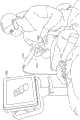
本发明的应用还可以包括与三维口内扫描装置有关的系统和方法,该三维口内扫描装置包括一个或更多个光场摄像头以及一个或更多个图案投射器。例如,在一些实施例中,提供了口内扫描装置。该装置可以包括细长的手持棒,该手持棒包括位于远端的探头。探头可以具有近端和远端。在口内扫描期间,探头可以放置在受试者的口腔中。根据本发明的一些应用,结构光投射器和光场摄像头可以设置在探头的近端,镜子设置在探头的远端。结构光投射器和光场摄像头可以被定位成面向镜子,并且镜子被定位成(a)将来自结构光投射器的光直接反射到被扫描的对象上,以及(b)将来自被扫描对象的光反射到光场摄像头。Applications of the present invention may also include systems and methods related to three-dimensional intraoral scanning devices comprising one or more light field cameras and one or more pattern projectors. For example, in some embodiments, an intraoral scanning device is provided. The device may comprise an elongated handheld wand including a probe at the distal end. A probe can have a proximal end and a distal end. During an intraoral scan, a probe may be placed in the subject's mouth. According to some applications of the present invention, the structured light projector and the light field camera can be arranged at the proximal end of the probe, and the mirror is arranged at the far end of the probe. The structured light projector and light field camera can be positioned to face the mirror, and the mirror is positioned to (a) reflect light from the structured light projector directly onto the object being scanned, and (b) reflect light from the object being scanned Reflected to the light field camera.
探头近端中的结构光投射器包括光源。在一些应用中,光源可以具有至少6度和/或小于30度的照射场。结构光投射器可以将来自光源的光聚焦在距光源至少30mm和/或小于140mm的投射器焦平面处。结构光投射器还可以包括图案生成器,该图案生成器设置在光源和投射器焦平面之间的光路中,当光源被激活以发射通过图案生成器的光时,图案生成器在投射器焦平面处生成结构光图案。A structured light projector in the proximal end of the probe includes a light source. In some applications, the light source may have an illumination field of at least 6 degrees and/or less than 30 degrees. A structured light projector may focus light from a light source at a projector focal plane at least 30mm and/or less than 140mm from the light source. The structured light projector may also include a pattern generator disposed in the light path between the light source and the focal plane of the projector, when the light source is activated to emit light through the pattern generator, the pattern generator is positioned at the focal plane of the projector. A structured light pattern is generated at the plane.
在一些应用中,探头近端中的光场摄像头可以具有至少6度和/或小于30度的视场。光场摄像头可以聚焦在距光场摄像头至少30mm和/或小于140mm的摄像头焦平面处。光场摄像头还可以包括光场摄像头传感器,该光场摄像头传感器包括(i)包括传感器像素阵列的图像传感器,以及(ii)设置在图像传感器前面的微透镜阵列,使得每个微透镜透镜设置在传感器像素的子阵列上。设置在光场摄像头传感器前面的物镜将被扫描对象的图像形成到光场摄像头传感器上。In some applications, the light field camera in the probe proximal end may have a field of view of at least 6 degrees and/or less than 30 degrees. The light field camera may be focused at a focal plane of the camera at least 30mm and/or less than 140mm from the light field camera. The light field camera may also include a light field camera sensor comprising (i) an image sensor including an array of sensor pixels, and (ii) a microlens array disposed in front of the image sensor such that each microlens lens is disposed at on the subarray of sensor pixels. An objective lens disposed in front of the light field camera sensor forms an image of the scanned object onto the light field camera sensor.
根据本发明的一些应用,一个或更多个结构光投射器和一个或更多个光场摄像头设置在探头的远端。结构光投射器和光场摄像头被定位成使得每个结构光投射器直接面向放置在其照射场中的棒外部的对象,并且每个摄像头直接面向放置在其视场中的棒外部的对象。来自每个投射器的投射结构光图案的至少40%在至少一个摄像头的视场中。According to some applications of the invention, one or more structured light projectors and one or more light field cameras are positioned at the distal end of the probe. The structured light projectors and light field cameras are positioned such that each structured light projector faces directly outside the rod placed in its field of illumination, and each camera directly faces objects outside the rod placed in its field of view. At least 40% of the projected structured light pattern from each projector is in the field of view of at least one camera.
探头远端中的一个或更多个结构光投射器各自包括光源。在一些应用中,相应的结构光投射器可以各自具有至少60度和/或小于120度的照射场。每个结构光投射器可以将来自光源的光聚焦在距离光源至少30mm和/或小于140mm的投射器焦平面处。每个结构光投射器还可以包括图案生成器,该图案生成器设置在光源和投射器焦平面之间的光路中,当光源被激活以发射通过图案生成器的光时,图案生成器在投射器焦平面处生成结构光图案。The one or more structured light projectors in the distal end of the probe each include a light source. In some applications, corresponding structured light projectors may each have an illumination field of at least 60 degrees and/or less than 120 degrees. Each structured light projector may focus light from the light source at a projector focal plane at least 30 mm and/or less than 140 mm from the light source. Each structured light projector may also include a pattern generator disposed in the light path between the light source and the focal plane of the projector, when the light source is activated to emit light through the pattern generator, the pattern generator projects Generate structured light patterns at the focal plane of the sensor.
在一些应用中,在探头远端中的一个或更多个光场摄像头可以各自具有至少60度和/或小于120度的视场。每个光场摄像头可以聚焦在距光场摄像头至少3mm和/或小于40mm的摄像头焦平面处。每个光场摄像头还可以包括光场摄像头传感器,该光场摄像头传感器包括(i)包括传感器像素阵列的图像传感器,以及(ii)设置在图像传感器前面的微透镜阵列,使得每个微透镜设置在传感器像素的子阵列上。设置在每个光场摄像头传感器前面的物镜将被扫描对象的图像形成到光场摄像头传感器上。In some applications, the one or more light field cameras in the probe distal end may each have a field of view of at least 60 degrees and/or less than 120 degrees. Each light field camera can be focused on a focal plane of the camera that is at least 3mm and/or less than 40mm away from the light field camera. Each light field camera may also include a light field camera sensor including (i) an image sensor including an array of sensor pixels, and (ii) a microlens array disposed in front of the image sensor such that each microlens is set on a subarray of sensor pixels. An objective lens disposed in front of each light field camera sensor forms an image of the scanned object onto the light field camera sensor.
因此,根据本发明的一些应用,提供了用于口内扫描的装置,该装置包括:Thus, according to some applications of the present invention, there is provided an apparatus for intraoral scanning comprising:
(A)细长手持棒,包括位于手持棒远端的探头,该探头具有近端和远端;(A) An elongated handheld wand including a probe at the distal end of the wand, the probe having a proximal end and a distal end;
(B)结构光投射器,设置在探头的近端,该结构光投射器:(B) a structured light projector, arranged at the proximal end of the probe, the structured light projector:
(a)具有6至30度的照射场,(a) have an irradiation field of 6 to 30 degrees,
(b)包括光源,以及(b) includes a light source, and
(c)被配置为将来自光源的光聚焦在距离光源30mm和140mm之间的投射器焦平面处,并且(c) configured to focus light from the light source at a projector focal plane between 30mm and 140mm from the light source, and
(d)包括设置在光源和投射器焦平面之间的光路中的图案生成器,该图案生成器被配置为当光源被激活以发射通过图案生成器的光时,在投射器焦平面处生成结构光图案。(d) comprising a pattern generator disposed in the optical path between the light source and the projector focal plane, the pattern generator configured to generate at the projector focal plane when the light source is activated to emit light through the pattern generator Structured light pattern.
(C)光场摄像头,设置在探头近端,该光场摄像头:(C) light field camera, arranged at the near end of the probe, the light field camera:
(a)具有6至30度的视场,(a) have a field of view of 6 to 30 degrees,
(b)被配置为聚焦在距离光场摄像头30mm至140mm之间的摄像头焦平面处,(b) configured to focus at the focal plane of the camera between 30mm and 140mm from the light field camera,
(c)包括光场摄像头传感器,该光场摄像头传感器包括(i)包括传感器像素阵列的图像传感器,以及(ii)设置在图像传感器前面的微透镜阵列,使得每个微透镜设置在传感器像素的子阵列上,以及(c) comprising a light field camera sensor comprising (i) an image sensor comprising an array of sensor pixels, and (ii) an array of microlenses disposed in front of the image sensor such that each microlens is disposed at the edge of the sensor pixel on the subarray, and
(d)包括物镜,设置在光场摄像头传感器的前面,并被配置为将被扫描对象的图像形成到光场摄像头传感器上;以及(d) comprising an objective lens disposed in front of the light field camera sensor and configured to form an image of the scanned object onto the light field camera sensor; and
(D)镜子,设置在手持棒的远端,(D) mirror, set at the distal end of the hand-held wand,
结构光投射器和光场摄像头被定位成面向镜子,并且镜子定位成(a)将来自结构光投射器的光直接反射到被扫描的对象上,以及(b)将来自被扫描对象的光反射到光场摄像头中。The structured light projector and light field camera are positioned facing the mirror, and the mirror is positioned to (a) reflect light from the structured light projector directly onto the object being scanned, and (b) reflect light from the scanned object onto In the light field camera.
对于一些应用,光源包括发光二极管(LED),并且图案生成器包括掩模。For some applications, the light source includes a light emitting diode (LED), and the pattern generator includes a mask.
对于一些应用,光源包括激光二极管。For some applications, the light source includes a laser diode.
对于一些应用,图案生成器包括衍射光学元件(DOE),被配置为生成结构光图案,作为离散的未连接的光点的分布。For some applications, the pattern generator includes a diffractive optical element (DOE) configured to generate the structured light pattern as a distribution of discrete, unconnected light spots.
对于一些应用,图案生成器包括折射微透镜阵列。For some applications, the pattern generator includes a refractive microlens array.
对于一些应用,探头的高度为14-17mm,探头的宽度为18-22mm,该高度和宽度限定了垂直于棒的纵轴的平面,光线通过探头的下表面进入探头,并且从探头的下表面到与下表面相对的探头的上表面测量探头的高度。For some applications, the height of the probe is 14-17mm, the width of the probe is 18-22mm, the height and width define a plane perpendicular to the longitudinal axis of the rod, the light enters the probe through the lower surface of the probe, and passes through the lower surface of the probe Measure the height of the probe to the upper surface of the probe opposite the lower surface.
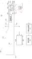
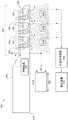
对于一些应用,该装置被配置为与输出装置一起使用,该装置还包括:For some applications, the device is configured for use with an output device, the device further comprising:
控制电路,被配置为:a control circuit configured to:
(a)驱动结构光投射器将结构光图案投射到棒外部的对象上,(a) driving the structured light projector to project the structured light pattern onto the object outside the stick,
(b)驱动光场摄像头捕获由从对象反射的结构光图案生成的光场,该光场包括(i)从对象反射的结构光图案的强度,和(ii)光线的方向;以及(b) driving the light field camera to capture a light field generated by the structured light pattern reflected from the object, the light field comprising (i) the intensity of the structured light pattern reflected from the object, and (ii) the direction of the light rays; and
至少一个计算机处理器,被配置为基于捕获的光场重建被扫描对象的表面的三维图像,并将图像输出到输出装置。At least one computer processor configured to reconstruct a three-dimensional image of the surface of the scanned object based on the captured light field and output the image to an output device.
对于一些应用:For some applications:
(a)棒外部的对象是受试者口内的牙齿,(a) the objects outside the stick are the teeth in the subject's mouth,
(b)控制电路被配置为驱动光场摄像头在牙齿上不存在粉末的情况下捕获由从牙齿反射的结构光图案生成的光场,并且(b) the control circuitry is configured to drive the light field camera to capture the light field generated by the structured light pattern reflected from the tooth in the absence of powder on the tooth, and
(c)计算机处理器被配置为基于在牙齿上没有粉末的情况下捕获的光场来重建牙齿的三维图像,并将图像输出到输出装置。(c) The computer processor is configured to reconstruct a three-dimensional image of the tooth based on the light field captured without powder on the tooth, and output the image to the output device.
对于一些应用,在图像传感器的中心区域中的每个传感器像素的子阵列包括比在图像传感器的外围区域中的每个传感器像素的子阵列少10-40%的像素,图像传感器的中心区域包括传感器像素总数的至少50%。For some applications, each sub-array of sensor pixels in the central region of the image sensor includes 10-40% fewer pixels than each sub-array of sensor pixels in the peripheral region of the image sensor, which includes At least 50% of the total number of pixels in the sensor.
对于一些应用,(a)设置在图像传感器的外围区域中的传感器像素的子阵列上的每个微透镜被配置为聚焦的深度比(b)设置在图像传感器的中心区域中的传感器像素的子阵列上的每个微透镜被配置为聚焦的深度大1.1-1.4倍。For some applications, (a) each microlens on a subarray of sensor pixels disposed in the peripheral region of the image sensor is configured to focus at a deeper depth than (b) a subarray of sensor pixels disposed in the central region of the image sensor Each microlens on the array is configured to have a depth of focus that is 1.1-1.4 times greater.
根据本发明的一些应用,还提供了一种装置,包括:According to some applications of the present invention, a device is also provided, comprising:
(A)细长手持棒,包括位于手持棒远端的探头,该探头具有近端和远端;(A) An elongated handheld wand including a probe at the distal end of the wand, the probe having a proximal end and a distal end;
(B)一个或更多个结构光投射器,设置在探头的远端,每个结构光投射器:(B) One or more structured light projectors, disposed at the distal end of the probe, each structured light projector:
(a)具有60至120度的照射场,(a) have an irradiation field of 60 to 120 degrees,
(b)包括光源,以及(b) includes a light source, and
(c)被配置为将来自光源的光聚焦在距离光源3mm和40mm之间的投射器焦平面处,并且(c) configured to focus light from the light source at a projector focal plane between 3mm and 40mm from the light source, and
(d)包括设置在光源和投射器焦平面之间的光路中的图案生成器,该图案生成器被配置为当光源被激活以发射通过图案生成器的光时,在投射器焦平面处生成结构光图案;以及(d) comprising a pattern generator disposed in the optical path between the light source and the projector focal plane, the pattern generator configured to generate at the projector focal plane when the light source is activated to emit light through the pattern generator structured light patterns; and
(C)一个或更多个光场摄像头,设置在探头远端,每个光场摄像头:(C) one or more light field cameras, arranged at the far end of the probe, each light field camera:
(a)具有60至120度的视场,(a) have a field of view of 60 to 120 degrees,
(b)被配置为聚焦在距离光场摄像头3mm至40mm之间的摄像头焦平面处,(b) configured to focus at the focal plane of the camera between 3mm and 40mm from the light field camera,
(c)包括光场摄像头传感器,该光场摄像头传感器包括(i)包括传感器像素阵列的图像传感器,以及(ii)设置在图像传感器前面的微透镜阵列,使得每个微透镜设置在传感器像素的子阵列上,以及(c) comprising a light field camera sensor comprising (i) an image sensor comprising an array of sensor pixels, and (ii) an array of microlenses disposed in front of the image sensor such that each microlens is disposed at the edge of the sensor pixel on the subarray, and
(d)包括物镜,设置在光场摄像头传感器的前面,并被配置为将被扫描对象的图像形成到光场摄像头传感器上;以及(d) comprising an objective lens disposed in front of the light field camera sensor and configured to form an image of the scanned object onto the light field camera sensor; and
结构光投射器和光场摄像头被定位成使得(a)每个结构光投射器直接面向放置在其照射场中的棒外部的对象,(b)每个摄像头直接面向放置在其视场中的棒外部的对象,以及(c)来自每个投射器的结构光图案的至少40%位于至少一个摄像头的视场中。The structured light projectors and light field cameras are positioned such that (a) each structured light projector is directly facing objects outside the rod placed in its illuminated field, (b) each camera is directly facing the rod placed in its field of view External objects, and (c) at least 40% of the structured light pattern from each projector are within the field of view of the at least one camera.
对于一些应用,探头的高度为10-14mm,探头的宽度为18-22mm,该高度和宽度限定了垂直于棒的纵轴的平面,光线通过探头的下表面进入探头,并且从探头的下表面到与下表面相对的探头的上表面测量探头的高度。For some applications, the height of the probe is 10-14mm, the width of the probe is 18-22mm, the height and width define a plane perpendicular to the longitudinal axis of the rod, the light enters the probe through the lower surface of the probe, and passes through the lower surface of the probe Measure the height of the probe to the upper surface of the probe opposite the lower surface.
对于一些应用,一个或更多个结构光投射器恰好是一个结构光投射器,并且一个或更多个结构光场摄像头恰好是一个光场摄像头。For some applications, one or more structured light projectors happens to be a structured light projector, and one or more structured light field cameras happens to be a light field camera.
对于一些应用,一个或更多个结构光投射器是多个结构光投射器,并且一个或更多个光场摄像头是多个光场摄像头。For some applications, the one or more structured light projectors is a plurality of structured light projectors and the one or more light field cameras is a plurality of light field cameras.
对于一些应用,该装置被配置为与输出装置一起使用,该装置还包括:For some applications, the device is configured for use with an output device, the device further comprising:
控制电路,配置为:The control circuit is configured as:
(a)驱动一个或更多个结构光投射器的每一个将结构光图案投射到棒外部的对象上,(a) driving each of the one or more structured light projectors to project a structured light pattern onto an object external to the wand,
(b)驱动一个或更多个光场摄像头捕获由从对象反射的结构光图案生成的光场,该光场包括(i)从对象反射的结构光图案的强度,和(ii)光线的方向;以及(b) driving one or more light field cameras to capture a light field generated by the structured light pattern reflected from the object, the light field comprising (i) the intensity of the structured light pattern reflected from the object, and (ii) the direction of the light rays ;as well as
至少一个计算机处理器,被配置为基于捕获的光场重建被扫描对象的表面的三维图像,并将图像输出到输出装置。At least one computer processor configured to reconstruct a three-dimensional image of the surface of the scanned object based on the captured light field and output the image to an output device.
对于一些应用:For some applications:
一个或更多个结构光投射器的至少一个是单色结构光投射器,被配置为将单色结构光图案投射到被扫描对象上,at least one of the one or more structured light projectors is a monochromatic structured light projector configured to project a monochromatic structured light pattern onto the scanned object,
一个或更多个光场摄像头的至少一个是单色光场摄像头,被配置为捕获由从被扫描的对象反射的单色结构光图案生成的光场,以及at least one of the one or more light field cameras is a monochrome light field camera configured to capture a light field generated by a monochrome structured light pattern reflected from the object being scanned, and
该装置还包括:(a)光源,被配置为将白光发射到被扫描的对象上;以及(b)摄像头,被配置为捕获被扫描对象的二维彩色图像。The apparatus also includes: (a) a light source configured to emit white light onto the object being scanned; and (b) a camera configured to capture a two-dimensional color image of the object being scanned.
对于一些应用,单色结构光投射器被配置为以420-470nm的波长投射结构光图案。For some applications, the monochromatic structured light projector is configured to project the structured light pattern at a wavelength of 420-470 nm.
根据本发明的一些应用,还提供了一种装置,包括:According to some applications of the present invention, a device is also provided, comprising:
(A)细长手持棒,包括位于手持棒远端的探头,该探头具有近端和远端;(A) An elongated handheld wand including a probe at the distal end of the wand, the probe having a proximal end and a distal end;
(B)结构光投射器,设置在探头的近端,该结构光投射器:(B) a structured light projector, arranged at the proximal end of the probe, the structured light projector:
(a)具有照射场,(a) has an irradiated field,
(b)包括光源,以及(b) includes a light source, and
(c)被配置为将来自光源的光聚焦在投射器焦平面处,并且(c) is configured to focus light from the light source at the projector focal plane, and
(d)包括设置在光源和投射器焦平面之间的光路中的图案生成器,该图案生成器被配置为当光源被激活以发射通过图案生成器的光时,在投射器焦平面处生成结构光图案;(d) comprising a pattern generator disposed in the optical path between the light source and the projector focal plane, the pattern generator configured to generate at the projector focal plane when the light source is activated to emit light through the pattern generator structured light pattern;
(C)光场摄像头,设置在探头近端,该光场摄像头:(C) light field camera, arranged at the near end of the probe, the light field camera:
(a)具有视场,(a) has a field of view,
(b)被配置为聚焦在摄像头焦平面处,(b) configured to focus at the camera focal plane,
(c)包括光场摄像头传感器,该光场摄像头传感器包括(i)包括传感器像素阵列的图像传感器,以及(ii)设置在图像传感器前面的微透镜阵列,使得每个微透镜设置在传感器像素的子阵列上,以及(c) comprising a light field camera sensor comprising (i) an image sensor comprising an array of sensor pixels, and (ii) an array of microlenses disposed in front of the image sensor such that each microlens is disposed at the edge of the sensor pixel on the subarray, and
(d)包括物镜,设置在光场摄像头传感器的前面,并被配置为将被扫描对象的图像形成到光场摄像头传感器上;以及(d) comprising an objective lens disposed in front of the light field camera sensor and configured to form an image of the scanned object onto the light field camera sensor; and
(D)镜子,设置在手持棒的远端,(D) mirror, set at the distal end of the hand-held wand,
结构光投射器和光场摄像头被定位成面向镜子,并且镜子定位成(a)将来自结构光投射器的光直接反射到被扫描对象上,以及(b)将来自被扫描对象的光反射到光场摄像头中。The structured light projector and light field camera are positioned facing the mirror, and the mirror is positioned to (a) reflect the light from the structured light projector directly onto the scanned object, and (b) reflect the light from the scanned object onto the light field camera.
根据本发明的一些应用,还提供了一种装置,包括:According to some applications of the present invention, a device is also provided, comprising:
(A)细长手持棒,包括位于手持棒远端的探头,该探头具有近端和远端;(A) An elongated handheld wand including a probe at the distal end of the wand, the probe having a proximal end and a distal end;
(B)一个或更多个结构光投射器,设置在探头的远端,每个结构光投射器:(B) One or more structured light projectors, disposed at the distal end of the probe, each structured light projector:
(a)具有照射场,(a) has an irradiated field,
(b)包括光源,以及(b) includes a light source, and
(c)被配置为将来自光源的光聚焦在投射器焦平面处,并且(c) is configured to focus light from the light source at the projector focal plane, and
(d)包括设置在光源和投射器焦平面之间的光路中的图案生成器,该图案生成器被配置为当光源被激活以发射通过图案生成器的光时,在投射器焦平面处生成结构光图案;以及(d) comprising a pattern generator disposed in the optical path between the light source and the projector focal plane, the pattern generator configured to generate at the projector focal plane when the light source is activated to emit light through the pattern generator structured light patterns; and
(C)一个或更多个光场摄像头,设置在探头远端,每个光场摄像头:(C) one or more light field cameras, arranged at the far end of the probe, each light field camera:
(a)具有视场,(a) has a field of view,
(b)被配置为聚焦在摄像头焦平面处,(b) configured to focus at the camera focal plane,
(c)包括光场摄像头传感器,该光场摄像头传感器包括(i)包括传感器像素阵列的图像传感器,以及(ii)设置在图像传感器前面的微透镜阵列,使得每个微透镜设置在传感器像素的子阵列上,以及(c) comprising a light field camera sensor comprising (i) an image sensor comprising an array of sensor pixels, and (ii) an array of microlenses disposed in front of the image sensor such that each microlens is disposed at the edge of the sensor pixel on the subarray, and
(d)包括物镜,设置在光场摄像头传感器的前面,并被配置为将被扫描对象的图像形成到光场摄像头传感器上;以及(d) comprising an objective lens disposed in front of the light field camera sensor and configured to form an image of the scanned object onto the light field camera sensor; and
结构光投射器和光场摄像头被定位成使得(a)每个结构光投射器直接面向放置在其照射场中的棒外部的对象,(b)每个摄像头直接面向放置在其视场中的棒外部的对象,以及(c)来自每个投射器的结构光图案的至少40%位于至少一个摄像头的视场中。The structured light projectors and light field cameras are positioned such that (a) each structured light projector is directly facing objects outside the rod placed in its illuminated field, (b) each camera is directly facing the rod placed in its field of view External objects, and (c) at least 40% of the structured light pattern from each projector are within the field of view of the at least one camera.
从以下结合附图对其应用的详细描述,将更全面地理解本发明。The present invention will be more fully understood from the following detailed description of its application when taken in conjunction with the accompanying drawings.
附图说明Description of drawings
图1是根据本发明的一些应用的手持棒(handheld wand)的示意图,其中,多个结构式光投射器和摄像头设置在手持棒的远端处的探头内;1 is a schematic diagram of a handheld wand according to some applications of the present invention, wherein a plurality of structured light projectors and cameras are disposed within a probe at the distal end of the handheld wand;
图2A-B分别是根据本发明的一些应用的摄像头和结构光投射器的定位配置的示意图;2A-B are schematic diagrams of positioning configurations of cameras and structured light projectors according to some applications of the present invention;
图2C是根据本发明的一些应用的描绘探头中的结构光投射器和摄像头的位置的多种不同配置的图表;FIG. 2C is a diagram depicting various configurations of positions of structured light projectors and cameras in probes, according to some applications of the invention;
图3是根据本发明的一些应用的结构光投射器的示意图;Figure 3 is a schematic diagram of a structured light projector according to some applications of the invention;
图4是根据本发明的一些应用的结构光投射器的示意图,该结构光投射器将离散的未连接的光点的分布投射到多个对象焦平面上;4 is a schematic diagram of a structured light projector that projects a distribution of discrete, unconnected spots of light onto multiple object focal planes, according to some applications of the invention;
图5A-B是根据本发明的一些应用的结构光投射器的示意图,该结构光投射器包括光束整形光学元件和设置在光束整形光学元件和图案生成光学元件之间的附加光学元件;5A-B are schematic diagrams of a structured light projector including a beam shaping optical element and an additional optical element disposed between the beam shaping optical element and the pattern generating optical element, according to some applications of the present invention;
图6A-B是根据本发明的一些应用的投射离散的未连接的光点的结构光投射器和检测光点的摄像头传感器的示意图;6A-B are schematic diagrams of a structured light projector projecting discrete unconnected spots of light and a camera sensor detecting the spots, according to some applications of the invention;
图7是根据本发明的一些应用概述用于生成数字三维图像的方法的流程图;Figure 7 is a flowchart outlining a method for generating a digital three-dimensional image according to some applications of the present invention;
图8是根据本发明的一些应用概述用于执行图7的方法中的特定步骤的方法的流程图;Figure 8 is a flowchart outlining a method for performing certain steps in the method of Figure 7, according to some applications of the present invention;
图9、图10、图11和图12是根据本发明的一些应用描述图8的步骤的简化示例的示意图;Figures 9, 10, 11 and 12 are diagrams illustrating simplified examples of the steps of Figure 8 according to some applications of the present invention;
图13是根据本发明的一些应用概述用于生成数字三维图像的方法中的其他步骤的流程图;13 is a flowchart outlining other steps in a method for generating a digital three-dimensional image, according to some applications of the present invention;
图14、图15、图16和图17是根据本发明的一些应用描述图13的步骤的简化示例的示意图;Figures 14, 15, 16 and 17 are diagrams illustrating simplified examples of the steps of Figure 13 according to some applications of the present invention;
图18是根据本发明的一些应用的包括漫反射器的探头的示意图;Figure 18 is a schematic illustration of a probe comprising a diffuse reflector according to some applications of the invention;
图19A-B是根据本发明的一些应用的结构光投射器和由激光二极管发射的光束的横截面的示意图,其中,示出图案生成光学元件设置在光束的光路中;19A-B are schematic diagrams of a structured light projector and a cross-section of a beam emitted by a laser diode, showing pattern generating optical elements disposed in the optical path of the beam, according to some applications of the present invention;
图20A-E是根据本发明的一些应用的用作结构光投射器中的图案生成光学元件的微透镜阵列的示意图;20A-E are schematic illustrations of microlens arrays used as pattern generating optics in structured light projectors, according to some applications of the invention;
图21A-C是根据本发明的一些应用的用作结构光投射器中的图案生成光学元件的复合二维衍射周期结构(compound 2-D diffractive periodic structure)的示意图;21A-C are schematic illustrations of compound 2-D diffractive periodic structures used as pattern generating optical elements in structured light projectors, according to some applications of the present invention;
图22A-B是示出根据本发明的一些应用的单个光学元件和包括光学元件的结构光投射器的示意图,该单个光学元件具有非球面第一侧和与第一侧相对的平面第二侧;22A-B are schematic diagrams illustrating a single optical element having an aspherical first side and a planar second side opposite the first side and a structured light projector including the optical element, according to some applications of the present invention ;
图23A-B是根据本发明的一些应用的轴锥透镜和包括轴锥透镜的结构光投射器的示意图;23A-B are schematic illustrations of an axicon and a structured light projector including an axicon, according to some applications of the invention;
图24A-B是示出根据本发明的一些应用的光学元件和包括光学元件的结构光投射器的示意图,该光学元件在第一侧上具有非球面表面并且在与第一侧相对的第二侧上具有平坦表面;24A-B are schematic diagrams showing an optical element having an aspheric surface on a first side and a second side opposite to the first side, and a structured light projector including an optical element according to some applications of the present invention. have a flat surface on the side;
图25是根据本发明的一些应用的结构光投射器中的单个光学元件的示意图;Figure 25 is a schematic diagram of a single optical element in a structured light projector according to some applications of the invention;
图26A-B是根据本发明的一些应用的具有多于一个激光二极管的结构光投射器的示意图;26A-B are schematic diagrams of structured light projectors with more than one laser diode, according to some applications of the invention;
图27A-B是根据本发明的一些应用的组合不同波长的激光二极管的不同方式的示意图;27A-B are schematic illustrations of different ways of combining laser diodes of different wavelengths according to some applications of the invention;
图28A是根据本发明的一些应用的手持棒的示意图,其中,结构光投射器和光场摄像头设置在手持棒的近端,镜子设置在手持棒远端处的探头内;28A is a schematic illustration of a handheld wand according to some applications of the invention, wherein a structured light projector and a light field camera are positioned at the proximal end of the handheld wand, and a mirror is positioned within a probe at the distal end of the handheld wand;
图28B是根据本发明的一些应用的图28A的手持棒的示意图,其中示出探头在受试者的口内;28B is a schematic illustration of the handheld wand of FIG. 28A showing the probe within the mouth of a subject, according to some applications of the invention;
图29A-B是根据本发明的一些应用的结构光投射器的示意图;29A-B are schematic illustrations of structured light projectors according to some applications of the invention;
图30是根据本发明的一些应用的光场摄像头和被捕获的三维对象的示意图;Figure 30 is a schematic illustration of a light field camera and captured three-dimensional objects according to some applications of the present invention;
图31是根据本发明的一些应用的手持棒的示意图,该手持式棒具有设置在手持棒的远端处的探头内的结构光投射器和光场摄像头;以及31 is a schematic illustration of a hand-held wand having a structured light projector and a light field camera disposed within a probe at the distal end of the hand-held wand, according to some applications of the invention; and
图32是根据本发明的一些应用的手持棒的示意图,其中,多个结构式光投射器和光场摄像头设置在手持棒的远端处的探头内。32 is a schematic illustration of a handheld wand in which a plurality of structured light projectors and a light field camera are disposed within a probe at the distal end of the handheld wand, according to some applications of the invention.
具体实施方式Detailed ways
现在参考图1,图1是根据本发明的一些应用的用于口内扫描的细长手持棒20的示意图。多个结构光投射器22和多个摄像头24结合到刚性结构26,该刚性结构26设置在手持棒的远端30处的探头28内。在一些应用中,在口内扫描期间,探头28进入受试者的口腔。Reference is now made to FIG. 1 , which is a schematic illustration of an
对于一些应用,结构光投射器22位于探头28内,使得每个结构光投射器22面向放置在其照射场中的位于手持棒20外部的对象32,而不是将结构光投射器定位在手持棒近端中并通过镜子反射光并随后到对象上来照射对象。类似地,对于一些应用,摄像头24位于探头28内,使得每个摄像头24面向放置在其视场中的位于手持棒20外部的对象32,而不是将摄像头定位在手持棒的近端中并通过镜子将光反射进入摄像头来观察对象。投射器和摄像头在探头28内的这种定位使得扫描仪能够在保持低剖面(profile)探头的同时具有整体大的视场。For some applications, the structured
在一些应用中,探头28的高度H1小于15mm,从下表面176(感测表面)到与下表面176相对的上表面178测量探头28的高度H1,来自被扫描对象32的反射光通过该下表面176进入探头28。在一些应用中,高度H1在10-15mm之间。In some applications, the height H1 of the probe 28 is less than 15 mm, and the height H1 of the probe 28 is measured from the lower surface 176 (sensing surface) to the
在一些应用中,摄像头24每个都具有至少45度的大视场β(beta),例如,至少70度,例如,至少80度,例如,85度。在一些应用中,视场可以小于120度,例如,小于100度,例如,小于90度。在由发明人进行的实验中,发现在80和90度之间的每个摄像头的视场β(beta)特别有用,因为它在像素尺寸、视场和摄像头重叠、光学质量和成本之间提供了良好的平衡。摄像头24可以包括摄像头传感器58和包括一个或更多个透镜的物镜光学器件60。为了能够近焦成像,摄像头24可以聚焦在对象焦平面50处,对象焦平面50距离与摄像头传感器相距最远的透镜1mm到30mm之间,例如,在4mm和24mm之间,例如,在5mm和11mm之间,例如,9mm-10mm。在发明人进行的实验中,发现距离与摄像头传感器相距最远的透镜5mm和11mm之间的对象焦平面50特别有用,因为在这个距离处很容易扫描牙齿,并且因为大多数牙齿表面的焦点很好。在一些应用中,摄像头24可以以每秒至少30帧的帧速率捕获图像,例如,以每秒至少75帧的帧速率,例如以每秒至少100帧的帧速率。在一些应用中,帧速率可以小于每秒200帧。In some applications,
如上所述,通过组合所有摄像头的相应视场而实现的大视场可以由于减少的图像拼接错误量而提高准确度,尤其是在无牙区域,其中牙龈表面光滑并且可能存在更少的清晰的高分辨率三维特征。具有更大的视场使得诸如牙齿的整体曲线等大的光滑特征能够出现在每个图像帧中,这提高了拼接从多个这样的图像帧获得的各个表面的准确度。As mentioned above, the large field of view achieved by combining the respective fields of view of all cameras can improve accuracy due to the reduced amount of image stitching errors, especially in edentulous areas where the gingival surface is smooth and there may be fewer sharp lesions. High resolution 3D features. Having a larger field of view enables large smooth features such as the overall curve of a tooth to appear in each image frame, which improves the accuracy of stitching individual surfaces obtained from multiple such image frames.
类似地,结构光投射器22每个可以具有至少45度的大的照射场α(alpha),例如,至少70度。在一些应用中,照射场α(alpha)可以小于120度,例如,小于100度。下面描述结构光投射器22的其他特征。Similarly, structured
对于一些应用,为了改善图像捕获,每个摄像头24具有多个离散的预设焦点位置,在每个焦点位置,摄像头聚焦在相应的对象焦平面50处。每个摄像头24可以包括从离散的预设焦点位置选择焦点位置的自动聚焦致动器,以改善给定的图像捕获。附加地或替代地,每个摄像头24包括延伸摄像头的焦深的光学光圈相位掩模(optical aperture phasemask),使得由每个摄像头形成的图像在距离与摄像头传感器相距最远的透镜1mm和30mm之间,例如,4mm和24mm之间,例如,5mm和11mm之间,例如,9mm至10mm的所有物距上保持聚焦。For some applications, to improve image capture, each
在一些应用中,结构光投射器22和摄像头24以紧密堆积和/或交替方式结合到刚性结构26,使得(a)每个摄像头视场的主要部分与邻近的摄像头的视场重叠,(b)每个摄像头的视场的主要部分与邻近的投射器的照射场重叠。可选地,至少20%,例如,至少50%,例如,至少75%的投射光图案在对象焦平面50处在至少一个摄像头的视场中,该对象焦平面50在距离与摄像头传感器相距最远的透镜至少4mm处。由于投射器和摄像头的可能的不同配置,在任何摄像头的视场中可能永远不会看到一些投射图案,并且在扫描期间,当扫描仪被移动时,一些投射图案可能被对象32阻挡而不能被观察。In some applications, structured
刚性结构26可以是非柔性结构,结构光投射器22和摄像头24结合到该结构,以便为探头28内的光学器件提供结构稳定性。将所有投射器和所有摄像头结合到共同的刚性结构有助于在变化的环境条件下(例如,由受试者口部可能引起的机械应力的条件下)保持每个结构光投射器22和每个摄像头24的光学器件的几何完整性。另外,刚性结构26有助于保持结构光投射器22和摄像头24的稳定结构完整性和相对于彼此的定位。如下文进一步描述的,当探头28进入和离开受试者的口腔或在受试者在扫描期间呼吸时,控制刚性结构26的温度有助于在大范围的环境温度下保持光学器件的几何完整性。
现在参考图2A-B,图2A-B分别是根据本发明的一些应用的摄像头24和结构光投射器22的定位配置的示意图。对于一些应用,为了改善口内扫描仪的整体视场和照射场,将摄像头24和结构光投射器22定位成使得它们不都面向相同的方向。对于一些应用,例如图2A中所示,多个摄像头24结合到刚性结构26,使得至少两个摄像头24的两个相应光轴46之间的角度θ(theta)为90度或更小,例如,35度或更小。类似地,对于一些应用,例如图2B中所示,多个结构光投射器22结合到刚性结构26,使得至少两个结构光投射器22的两个相应光轴48之间的角度
现在参考图2C,图2C是描绘根据本发明的一些应用的探头28中的结构光投射器22和摄像头24的位置的多种不同配置的图表。结构光投射器22在图2C中用圆圈表示,摄像头24在图2C中用矩形表示。注意,矩形用于表示摄像头,因为通常,每个摄像头传感器58和每个摄像头24的视场β(beta)具有1:2的纵横比。图2C的列(a)示出了结构光投射器22和摄像头24的各种配置的鸟瞰图。在列(a)的第一行中标记的x轴对应于探头28的中心纵轴。列(b)示出了从与探头28的中心纵轴同轴的视线观察的各种配置的摄像头24的侧视图。类似于图2A,图2C的列(b)示出了摄像头24,被定位成使得光轴46相对于彼此成90度或更小的角度,例如35度或更小的角度。列(c)示出了从垂直于探头28的中心纵轴的视线观察的各种配置的摄像头24的侧视图。Reference is now made to FIG. 2C , which is a diagram depicting a number of different configurations for the location of structured
通常,最远侧(朝向图2C中的正x方向)和最近侧(朝向图2C中的负x方向)摄像头24被定位成使得它们的光轴46相对于挨着的最接近的摄像头24稍微向内转动,例如,成90度或更小的角度,例如35度或更小的角度。位于更中心的摄像头24,即,既不是最远侧摄像头24也不是最近侧摄像头24,被定位成使得直接面向探头外,它们的光轴46基本上垂直于探头28的中心纵轴。应注意,在行(xi)中,投射器22位于探头28的最远侧位置,因此该投射器22的光轴48指向内部,允许从该特定投射器22投射的更多数量的光点33被更多摄像头24看到。Typically, the farthest (towards the positive x-direction in FIG. 2C ) and proximal-most (towards the negative x-direction in FIG. 2C )
通常,探头28中的结构光投射器22的数量的范围可以从两个(例如,如图2C的行(iv)所示)到六个(例如,如行(xii)所示)。通常,探头28中的摄像头24的数量的范围可以从四个(例如,如行(iv)和(v)所示)到七个(例如,如行(ix)所示)。注意,图2C中所示的各种配置只是作为示例而非限制,并且本发明的范围包括未示出的额外配置。例如,本发明的范围包括位于探头28中的多于五个的投射器22和位于探头28中的多于七个的摄像头。In general, the number of structured
在示例性应用中,用于口内扫描的装置(例如,口内扫描仪)包括细长的手持棒,该手持棒包括:位于细长手持棒的远端处的探头;至少两个光投射器,设置在探头内;以及至少四个摄像头,设置于探头内。每个光投射器可以包括:至少一个光源,被配置为被激活时生成光;以及图案生成光学元件,被配置为当发射通过图案生成光学元件的光时生成光图案。至少四个摄像头的每一个可以包括摄像头传感器和一个或更多个透镜,其中至少四个摄像头的每一个被配置为捕获描绘口内表面上投射的光图案的至少一部分的多个图像。至少两个光投射器和至少四个摄像头中的大多数可以被布置成至少两行,其每行大致平行于探头纵轴,该至少两行包括至少第一行和第二行。In an exemplary application, an apparatus for intraoral scanning (eg, an intraoral scanner) includes an elongated handheld wand comprising: a probe located at a distal end of the elongated handheld wand; at least two light projectors, set in the probe; and at least four cameras set in the probe. Each light projector may include: at least one light source configured to generate light when activated; and a pattern generating optical element configured to generate a light pattern when emitting light through the pattern generating optical element. Each of the at least four cameras may include a camera sensor and one or more lenses, wherein each of the at least four cameras is configured to capture a plurality of images depicting at least a portion of the light pattern projected on the intraoral surface. Most of the at least two light projectors and the at least four cameras may be arranged in at least two rows each substantially parallel to the probe longitudinal axis, the at least two rows including at least a first row and a second row.
在进一步的应用中,至少四个摄像头的沿着纵轴的最远侧摄像头和沿着纵轴的最近侧摄像头被定位成使得从垂直于纵轴的视线,它们的光轴相对于彼此成90度或更小的角度。第一行中的摄像头和第二行中的摄像头可以被定位成使得从与探头纵轴同轴的视线,第一行中的摄像头的光轴相对于第二行中的摄像头的光轴成90度或更小的角度。除了最远侧摄像头和最近侧摄像头之外的至少四个摄像头的其余部分具有基本平行于探头的纵轴的光轴。至少两行的每一行可以包括交替序列的光投射器和摄像头。In a further application, the most distal camera along the longitudinal axis and the most proximal camera along the longitudinal axis of the at least four cameras are positioned such that their optical axes are at 90° relative to each other from a line of sight perpendicular to the longitudinal axis. degrees or less. The cameras in the first row and the cameras in the second row may be positioned such that, from a line of sight coaxial with the probe longitudinal axis, the optical axes of the cameras in the first row are at 90° to the optical axes of the cameras in the second row. degrees or less. The remainder of the at least four cameras other than the most distal camera and the proximal most camera have optical axes substantially parallel to the longitudinal axis of the probe. Each of the at least two rows may include alternating sequences of light projectors and cameras.
在进一步的应用中,至少四个摄像头包括至少五个摄像头,至少两个光投射器包括至少五个光投射器,第一行中的最近侧组件是光投射器,第二行中的最近侧组件是是摄像头。In a further application, the at least four cameras include at least five cameras, the at least two light projectors include at least five light projectors, the closest component in the first row is a light projector, the closest component in the second row The component is the camera.
在进一步的应用中,沿着纵轴的最远侧摄像头和沿着纵轴的最近侧摄像头被定位成使得从垂直于纵轴的视线,它们的光轴相对于彼此成35度或更小的角度。第一行中的摄像头和第二行中的摄像头可以被定位成使得从与探头纵轴同轴的视线,第一行中的摄像头的光轴相对于第二行中的摄像头的光轴成35度或更小的角度。In a further application, the most distal camera along the longitudinal axis and the most proximal camera along the longitudinal axis are positioned such that their optical axes are 35 degrees or less relative to each other from a line of sight perpendicular to the longitudinal axis. angle. The cameras in the first row and the cameras in the second row may be positioned such that, from a line of sight coaxial with the probe longitudinal axis, the optical axes of the cameras in the first row are at 35° to the optical axes of the cameras in the second row. degrees or less.
在进一步的应用中,对应于距探头的距离,至少四个摄像头可以具有沿纵轴的25-45mm的组合的视场和沿z轴的20-40mm的视场。In a further application, the at least four cameras may have a combined field of view of 25-45 mm along the longitudinal axis and 20-40 mm along the z-axis, corresponding to the distance from the probe.
现在参考图3,图3是根据本发明的一些应用的结构光投射器22的示意图。在一些应用中,结构光投射器22包括激光二极管36、光束整形光学元件40和图案生成光学元件38,该图案生成光学元件38生成离散的未连接的光点的分布34(下面将参考图4进一步讨论)。在一些应用中,结构光投射器22可以被配置为当激光二极管36发射通过图案生成光学元件38的光时,在与图案生成光学元件38相距1mm和30mm之间,例如4mm和24mm之间的所有平面处生成离散的未连接的光点的分布34。对于一些应用,离散的未连接的光点的分布34聚焦在位于1mm和30mm之间例如在4mm和24mm之间的一个平面上,而所有其它位于1mm和30mm之间的平面,例如,在4mm和24mm之间的其它平面,仍然包含离散的未连接的光点。虽然上面描述为使用激光二极管,但应该理解,这是示例性和非限制性的应用。其他光源可以用在其他应用中。此外,尽管描述为投射离散的未连接的光点的图案,但应该理解,这是示例性且非限制性的应用。其他光图案或阵列,包括但不限于线、网格、棋盘格和其他阵列,可以用在其他应用中。Reference is now made to FIG. 3, which is a schematic illustration of a structured
图案生成光学元件38可以被配置为具有至少80%,例如,至少90%的光转换效率(light throughput effciency)(即,进入图案的光与落在图案生成光学元件38上的总光的比例)。The pattern generating optical element 38 may be configured to have a light throughput efficiency (i.e., the ratio of light entering the pattern to the total light falling on the pattern generating optical element 38) of at least 80%, for example, at least 90%. .
对于一些应用,各个结构光投射器22的相应激光二极管36发射不同波长的光,即,至少两个结构光投射器22的相应激光二极管36分别发射两个不同波长的光。对于一些应用,至少三个结构光投射器22的相应激光二极管36分别发射三种不同波长的光。例如,可以使用红色、蓝色和绿色激光二极管。对于一些应用,至少两个结构光投射器22的相应激光二极管36分别发射两种不同波长的光。例如,在一些应用中,有六个结构光投射器22设置在探头28内,其中三个包含蓝色激光二极管,其中三个包含绿色激光二极管。For some applications, the
现在参考图4,图4是根据本发明的一些应用的结构光投射器22的示意图,该结构光投射器22将离散的未连接的光点的分布投射到多个对象焦平面上。被扫描的对象32可以是受试者口内的一个或更多个牙齿或其他口内对象/组织。牙齿的有些半透明和光滑的特性可能影响投射的结构光图案的对比度。例如,(a)一些击中牙齿的光可能散射到口内场景内的其他区域,导致一定数量的杂散光,以及(b)一些光可能穿透牙齿并随后在任何其他点处从牙齿出来。因此,在不使用诸如用不透明粉末涂覆牙齿等对比度增强装置的情况下,为了改善结构光照射下的口内场景的图像捕获,发明人已经认识到离散的未连接的光点的稀疏分布34可以在减少投射光量同时保持有用的信息量之间提供改进的平衡。分布34的稀疏性可以通过以下(a)与(b)之比率来表征:Reference is now made to FIG. 4, which is a schematic diagram of a structured
(a)照射场α(alpha)中的正交平面44上的照射面积,即,照射场α(alpha)中的正交平面44上的所有投射光点33的面积之和,(a) the irradiated area on the
(b)照射场α(alpha)中的正交平面44上的非照射面积。在一些应用中,稀疏度比率可以是至少1:150和/或小于1:16(例如,至少1:64和/或小于1:36)。(b) The non-irradiated area on the
在一些应用中,在扫描期间,每个结构光投射器22将至少400个离散的未连接的光点33投射到口内三维表面上。在一些应用中,在扫描期间,每个结构光投射器22将少于3000个离散的未连接的光点33投射到口内表面上。为了从投射的稀疏分布34重建三维表面,必须确定各个投射光点33和由摄像头24检测的光点之间的对应关系,如下面参考图7至图19进一步描述的。In some applications, each structured
对于一些应用,图案生成光学元件38是衍射光学元件(DOE)39(图3),当激光二极管36发射光通过DOE而到达对象32上时,该DOE生成离散的未连接的光点33的分布34。如在整个本申请中本文所使用的,包括在权利要求中,光点被定义为具有任何形状的小面积光。对于一些应用,不同结构光投射器22的相应DOE 39生成具有不同相应形状的光点,即由特定DOE 39生成的每个光点33具有相同的形状,并且由至少一个DOE 39生成的光点33的形状是不同于由至少一个其他DOE 39生成的光点33的形状。举例来说,DOE 39中的一些可以生成圆形光点33(例如图4中所示),DOE 39中的一些可以生成方形光点,DOE 39中的一些可以生成椭圆光点。可选地,一些DOE 39可以生成连接或未连接的线图案。For some applications, pattern generating optical element 38 is a diffractive optical element (DOE) 39 (FIG. 3) that generates a distribution of discrete
现在参考图5A-B,图5A-B是根据本发明的一些应用的结构光投射器22的示意图,该结构光投射器22包括光束整形光学元件40和设置在光束整形光学元件40和图案生成光学元件38(例如DOE 39)之间的附加光学元件。可选地,光束整形光学元件40是准直透镜130。准直透镜130可以被配置为具有小于2mm的焦距。可选地,焦距可以至少为1.2mm。对于一些应用,当激光二极管36发射通过光学元件42的光时,设置在光束整形光学元件40和图案生成光学元件38(例如DOE 39)之间的附加光学元件42生成贝塞尔光束。在一些应用中,贝塞尔光束通过DOE 39传输,使得所有离散的未连接的光点33保持小直径(例如小于0.06mm、例如小于0.04mm、例如小于0.02mm),通过一系列正交平面44(例如,每个正交平面位于距离DOE 39的1mm和30mm之间,例如,距离DOE 39的4mm和24mm之间,等等)。在本专利申请的上下文中,光点33的直径被定义为光点强度的半峰全宽(FWHM)。Reference is now made to FIGS. 5A-B , which are schematic illustrations of a structured
尽管以上描述的所有光点都小于0.06mm,但是具有接近这些范围的上端(例如,仅略小于0.06mm或0.02mm)的直径并且也靠近投射器22的照射场的边缘的一些光点,当它们在与DOE 39正交的几何平面相交时,可以被延长。对于这种情况,当它们与以DOE 39为中心并具有1mm和30mm之间的半径的几何球的内表面相交时测量它们的直径是有用的,该半径对应于距DOE 39达1mm和30mm之间的相应正交平面的距离。如本申请全文所用,包括在权利要求中,“几何”一词是用于与理论几何构造(例如平面或球体)相关,并且不是任何物理装置的一部分。While all of the spots described above are smaller than 0.06 mm, some spots with diameters near the upper end of these ranges (e.g., only slightly smaller than 0.06 mm or 0.02 mm) and also near the edge of the illuminated field of the
对于一些应用,当贝塞尔光束通过DOE 39传输时,除了直径小于0.06mm的光点之外,还生成直径大于0.06mm的光点33。For some applications, when a Bessel beam is transmitted through the
对于一些应用,光学元件42是轴锥透镜45,例如图5A中所示并且如在下文中参考图23A-B进一步描述的。或者,光学元件42可以是环形光圈环(annular aperture ring)47,例如图5B中所示。保持小直径的光点提高整个焦深的三维分辨率和精度。在没有光学元件42(例如,轴锥透镜45或环形光圈环47)的情况下,由于衍射和散焦,当你远离最佳聚焦平面移动时,光点33的尺寸可以变化,例如变得更大。For some applications, optical element 42 is an axicon lens 45, such as that shown in FIG. 5A and described further below with reference to FIGS. 23A-B. Alternatively, optical element 42 may be an annular aperture ring 47, such as shown in FIG. 5B. Keeping the spot diameter small improves 3D resolution and precision throughout the depth of focus. In the absence of an optical element 42 (e.g., an axicon 45 or an annular aperture ring 47), due to diffraction and defocusing, the size of the
现在参考图6A-B,图6A-B是根据本发明的一些应用的投射离散的未连接的光点33的结构光投射器22和检测光点33'的摄像头传感器58的示意图。对于一些应用,提供了一种用于确定口内表面上的投射光点33与相应摄像头传感器58上的检测到的光点33'之间的对应关系的方法。一旦确定了对应关系,就重建表面的三维图像。每个摄像头传感器58具有像素阵列,对于每个像素存在相应的摄像头光线86。类似地,对于来自每个投射器22的每个投射光点33,存在相应的投射器光线88。每个投射器光线88对应于至少一个摄像头传感器58上的像素的相应路径92。因此,如果摄像头看到由特定投射器光线88投射的光点33',则该光点33'必然会由对应于该特定投射器光线88的像素的特定路径92上的像素检测到。具体参考图6B,示出了各个投射器光线88和相应摄像头传感器路径92之间的对应关系。投射器光线88'对应于摄像头传感器路径92',投射器光线88”对应于摄像头传感器路径92”,投射器光线88”'对应于摄像头传感器路径92”'。例如,如果特定的投射器光线88将光点投射到充满灰尘的空间中,则空气中的灰尘线将被照射。由摄像头传感器58检测到的该灰尘线将在摄像头传感器58上遵循与对应于特定投射器光线88的摄像头传感器路径92相同的路径。Reference is now made to FIGS. 6A-B , which are schematic diagrams of structured
在校准过程期间,基于对应于每个摄像头24的摄像头传感器58上的像素的摄像头光线86和对应于来自每个结构光投射器22的投射光点33的投射器光线88来存储校准值。例如,针对(a)对应于每个摄像头24的摄像头传感器58上的相应多个像素的多个摄像头光线86,以及(b)对应于来自每个结构光投射器22的相应多个投射光点33的多个投射器光线88,来存储校准值。During the calibration process, calibration values are stored based on
举例来说,可以使用以下校准过程。从下方照射高精度点目标,例如白色背景上的黑点,并且用所有摄像头拍摄目标的图像。然后,点目标垂直地朝向摄像头移动,即沿z轴移动到目标平面。计算在所有相应z轴位置中的所有点的点中心,以在空间中创建点的三维网格。然后使用失真和摄像头针孔模型来找到相应点中心的每个三维位置的像素坐标,因此针对每个像素将摄像头光线定义为源自方向朝向三维网格中的对应点中心的像素的光线。可以内插对应于网格点之间的像素的摄像头光线。对于各个激光二极管36的所有相应波长重复上述摄像头校准过程,使得对于每个波长,包括在所存储的校准值中的是对应于每个摄像头传感器58上的每个像素的摄像头光线86。For example, the following calibration procedure can be used. A high-precision point target, such as a black dot on a white background, is illuminated from below and an image of the target is captured with all cameras. The point target is then moved vertically towards the camera, i.e. along the z-axis to the target plane. Calculate the point centers of all points in all corresponding z-axis positions to create a three-dimensional grid of points in space. The distortion and the camera pinhole model are then used to find the pixel coordinates of each 3D position of the corresponding point center, thus defining for each pixel a camera ray as the ray originating from the pixel directed towards the corresponding point center in the 3D grid. Camera rays corresponding to pixels between grid points can be interpolated. The camera calibration process described above is repeated for all corresponding wavelengths of each
在校准了摄像头24并且存储了所有摄像头光线86值之后,可以如下校准结构光投射器22。使用平坦的无特征目标,并且一次打开一个结构光投射器22。每个光点位于至少一个摄像头传感器58上。由于现在校准了摄像头24,因此基于多个不同摄像头中的光点的图像通过三角测量来计算每个光点的三维光点位置。利用位于多个不同z轴位置处的无特征目标重复上述过程。无特征目标上的每个投射光点将限定在空间中源自投射器的投射器光线。After the
现在参考图7,图7是根据本发明的一些应用概述用于生成数字三维图像的方法的流程图。在图7概述的方法的步骤62和64中,每个结构光投射器22被驱动以在口内三维表面上投射离散未连接的光点33的分布34,并且每个摄像头24被驱动以捕获包括至少一个光点33的图像。基于指示(a)对应于每个摄像头24的摄像头传感器58上的每个像素的摄像头光线86,以及(b)对应于来自每个结构光投射器22的每个投射的光点33的投射器光线88的存储的校准值,在步骤66中使用处理器96(图1)运行对应算法,下面将参考图8至图12进一步描述。一旦解决了对应关系,就在步骤68中计算口内表面上的三维位置,并用于生成口内表面的数字三维图像。此外,使用多个摄像头24捕获口内场景提供了通过摄像头数量的平方根的因子提供了捕获中噪声改善的信号。Reference is now made to FIG. 7, which is a flowchart outlining a method for generating a digital three-dimensional image, according to some applications of the present invention. In steps 62 and 64 of the method outlined in FIG. 7, each structured
现在参考图8,图8是根据本发明的一些应用概述图7中的步骤66的对应算法的流程图。基于存储的校准值,映射所有投射器光线88和对应于所有检测到的光点33'的所有摄像头光线86(步骤70),并且识别至少一个摄像头光线86和至少一个投射器光线88的所有交叉点98(图10)(步骤72)。图9和图10分别是图8的步骤70和72的简化示例的示意图。如图9所示,对应于摄像头24的摄像头传感器58上的总共八个检测到的光点33',将三个投射器光线88与八个摄像头光线86一起映射。如图10所示,识别出十六个交叉点98。Reference is now made to FIG. 8 , which is a flowchart outlining an algorithm corresponding to step 66 in FIG. 7 according to some applications of the present invention. Based on the stored calibration values, all
在图8的步骤74和76中,处理器96确定投射光点33和检测光点33'之间的对应关系,以便识别表面上每个投射光点33的三维位置。图11是使用上一段中描述的简化示例描绘图8的步骤74和76的示意图。对于给定的投射器光线i,处理器96“查看”其中一个摄像头24的摄像头传感器58上的相应摄像头传感器路径90。沿摄像头传感器路径90的每个检测到的光点j将具有在交叉点98处与给定投射器光线i相交的摄像头光线86。交叉点98限定了空间中的三维点。然后,处理器96“查看”在其他摄像头24的相应摄像头传感器58'上的对应于给定投射器光线i的摄像头传感器路径90',并识别有多少其他摄像头24在它们相应的对应给定的投射器光线i的摄像头传感器路径90'上还检测到相应光点k,该光点k的摄像头光线86'与由交叉点98限定的空间中的相同三维点相交。对沿摄像头传感器路径90的所有检测到的光点j重复该过程,并且将最多数量的摄像头24“同意”光点j识别为从给定投射器光线i投射到表面上的光点33(图12)。也就是说,投射器光线i被识别为生成检测到的光点j的特定投射器光线88,对于该光点j,最高数量的其他摄像头检测到相应的光点k。因此,计算出光点33在表面上的三维位置。In
例如,如图11所示,所有四个摄像头在与投射器光线i相对应的各个摄像头传感器路径上检测相应的光点,其相应的摄像头光线在交叉点98处与投射器光线i相交,交叉点98被限定为对应于检测到的光点j的摄像头光线86和投射器光线i的交叉点。因此,所有四个摄像头都被称为“同意”在交叉点98处存在由投射器光线i投射的光点33。然而,当对下一个光点j'重复该过程时,其他摄像头中没有一个在与投射器光线i相对应的它们各个摄像头传感器路径上检测到相应的光点,其相应的摄像头光线在交叉点98'处与投射器光线i相交,该交叉点98'被限定为摄像头光线86”(对应于检测到的光点j')与投射器光线i的交叉点。因此,只有一个摄像头被称为“同意”在交叉点98'处存在由投射器光线i投射的光点33,而四个摄像头“同意”在交叉点98处存在由投射器光线i投射的光点33。因此,投射器光线i被识别为通过在交叉点98处将光点33投射到表面上而生成检测到的光点j的特定投射器光线88(图12)。根据图8的步骤78,并且如图12所示,在交叉点98处计算出口内表面上的三维位置35。For example, as shown in FIG. 11, all four cameras detect corresponding points of light on the respective camera sensor paths corresponding to projector ray i whose corresponding camera ray intersects projector ray i at
现在参考图13,图13是根据本发明的一些应用概述对应算法中的其他步骤的流程图。一旦确定了表面上的位置35,就不考虑投射光点j的投射光线i,以及对应于光点j和相应光点k的所有摄像头光线86和86'(步骤80),并且对于下一个投射器光线i再次运行对应算法(步骤82)。图14描绘了在去除在位置35处投射光点33的特定投射器光线i之后的上文描述的简化示例。根据图13的流程图中的步骤82,然后对于下一个投射器光线i再次运行对应算法。如图14所示,剩余数据显示三个摄像头“同意”在交叉点98处存在光点33,交叉点98由对应于检测到的光点j的摄像头光线86与投射器光线i的交叉点限定。因此,如图15所示,在交叉点98处计算出三维位置37。Reference is now made to FIG. 13 , which is a flowchart outlining other steps in corresponding algorithms according to some applications of the invention. Once the
如图16所示,一旦确定了表面上的三维位置37,就不考虑投射光点j的投射光线i,以及对应于光点j和相应光点k的所有摄像头光线86和86'。剩余数据显示在交叉点98处存在由投射器光线i投射的光点33并且在交叉点98处计算出表面上的三维位置41。如图17所示,根据简化示例,结构光投射器22的三个投射器光线88的三个投射光点33现在已经位于表面上的三维位置35、37和41处。在一些应用中,每个结构光投射器22投射400-3000个光点33。一旦解决了所有投射器光线88的对应关系,可以使用重建算法来使用计算的投射光点33的三维位置来重建表面的数字图像。As shown in Figure 16, once the three-dimensional position 37 on the surface is determined, the projection ray i that casts spot j, and all
再次参考图1。对于一些应用,存在至少一个结合到刚性结构26的均匀光投射器118。均匀光投射器118将白光发射到被扫描的对象32上。至少一个摄像头(例如摄像头24的其中之一)被配置为使用来自均匀光投射器118的照射来捕获对象32的二维彩色图像。处理器96可以运行表面重建算法,该算法将使用来自结构光投射器22的照射捕获的至少一个图像与使用来自均匀光投射器118的照射捕获的多个图像组合以生成口内三维表面的三维图像。使用结构光和均匀照射的组合增强了口内扫描仪的整体捕获,并且可以帮助减少处理器96在运行对应算法时需要考虑的选项的数量。Referring again to FIG. 1 . For some applications, there is at least one uniform
对于一些应用,多个结构光投射器22被同时驱动以在口内三维表面上投射它们相应的离散的未连接的光点33的分布34。或者,可以驱动多个结构光投射器22以在不同的各个时间在口内三维表面上投射它们相应的离散的未连接的光点33的分布34,例如,以预定的顺序,或者以在扫描期间动态确定的顺序。或者,对于一些应用,可以驱动单个结构光投射器22以投射分布34。For some applications, multiple structured
动态确定在扫描期间激活哪个结构光投射器22可以改善扫描的整体信号质量,因为一些结构光投射器可以在口腔内的一些区域中相对于其他区域具有更好的信号质量。例如,当扫描受试者的上颚(上颌区域)时,红色投射器往往具有比蓝色投射器更好的信号质量。另外,在扫描期间可能遇到口腔内难以看见的区域,例如牙齿缺失或大牙齿之间的狭窄裂缝的区域。在这些类型的情况下,在扫描期间动态地确定激活哪个结构光投射器22允许激活可能具有更好视线的特定投射器。Dynamically determining which structured
对于一些应用,不同的结构光投射器22可以被配置成聚焦在不同的对象焦平面处。在扫描期间动态确定激活哪个结构光投射器22允许根据取决于距当前正被扫描的区域的距离的它们各自的对象焦平面激活特定的结构光投射器22。For some applications, different structured
对于一些应用,在特定时间采集的所有数据点都用作刚性点云(rigid pointcloud),并且以每秒超过10次捕获的帧速率捕获多个这样的点云。然后使用配准算法(例如,迭代最近点(ICP))将多个点云拼接在一起,以创建密集点云。然后可以使用表面重建算法来生成对象32的表面的表示。For some applications, all data points acquired at a particular time are used as a rigid point cloud, and multiple such point clouds are captured at a frame rate exceeding 10 captures per second. Multiple point clouds are then stitched together using a registration algorithm such as Iterative Closest Point (ICP) to create a dense point cloud. A surface reconstruction algorithm may then be used to generate a representation of the surface of
对于一些应用,至少一个温度传感器52被结合到刚性结构26并测量刚性结构26的温度。设置在手持棒20内的温度控制电路54(a)从温度传感器52接收指示刚性结构26的温度的数据,以及(b)响应于接收的数据激活温度控制单元56。温度控制单元56(例如,PID控制器)将探头28保持在期望的温度(例如,在35和43摄氏度之间、在37和41摄氏度之间等)。将探头28保持在35摄氏度以上,例如37摄氏度以上,减少了手持棒20的玻璃表面的雾化,当探头28进入口腔内时,通过手持棒20的玻璃表面,结构式光投射器22进行投射,摄像头2进行观察,口腔通常在37摄氏度左右或以上。将探头28保持在43度以下,例如低于41摄氏度,防止不适或疼痛。For some applications, at least one
另外,为了在扫描期间使用存储的摄像头光线和投射器光线的校准值,可以防止摄像头24和结构光投射器22的温度变化,从而保持光学器件的几何完整性。温度的变化可能导致探头28的长度由于热膨胀而改变,这反过来可能导致相应的摄像头和投射器位置偏移。由于在这种热膨胀期间可能在探头28内积聚的不同类型的应力,也可能生成扭曲,导致相应的摄像头光线和投射器光线的角度也生成偏移。在摄像头和投射器内,由于温度变化也可能生成几何变化。例如,DOE 39可能膨胀和改变投射的图案,温度变化可能影响摄像头透镜的折射率,或者温度变化可能改变激光二极管36发射的波长。因此,除了将探头28保持在上述范围内的温度之外,温度控制单元56还可以在使用手持棒20时防止探头28的温度变化超过1度,从而保持设置在探头28内的光学器件的几何完整性。例如,如果温度控制单元56将探头28保持在39摄氏度的温度,则温度控制单元56将进一步确保在使用期间探头28的温度不低于38摄氏度或高于40摄氏度。In addition, temperature variations of the
对于一些应用,通过使用加热和冷却的组合将探头28保持在其受控的温度。例如,温度控制单元56可包括加热器,例如多个加热器,以及冷却器,例如热电冷却器。如果探头28的温度降至38摄氏度以下,则可以使用加热器来升高探头28的温度,如果探头28的温度高于40摄氏度,则可以使用热电冷却器来降低探头28的温度。For some applications, the probe 28 is maintained at its controlled temperature by using a combination of heating and cooling. For example, the
或者,对于一些应用,通过仅使用加热而不使用冷却将探头28保持在其受控温度。激光二极管36和衍射和/或折射图案生成光学元件的使用有助于保持能量有效的结构光投射器,从而限制探头28在使用期间不会升温;激光二极管36可以使用小于0.2瓦特的功率,同时以高亮度发射,并且衍射和/或折射图案生成光学元件利用所有发射的光(例如与阻止一些光线撞击对象的掩模相反)。然而,外部环境温度,例如在受试者的口腔内遇到的那些温度,可能引起对探头28的加热。为了克服这一点,可以通过设置在手持棒20内的导热元件94(例如,热管)将热量从探头28中抽出,使得导热元件94的远端95与刚性结构26接触,并且近端99与手持棒20的近端100接触。由此,热量从刚性结构26传递到手持棒20的近端100。可替换地或另外地,设置在手持棒20的手柄区域174中的风扇可用于从探头28抽走热量。Alternatively, for some applications, the probe 28 is maintained at its controlled temperature by using only heating and no cooling. The use of
对于一些应用,可替换地或另外地,为了通过防止探头28的温度变化超过温度的阈值变化来维持光学器件的几何完整性,处理器96可以分别在对应于不同温度的多组校准数据之间进行选择。例如,阈值变化可以是1摄氏度。基于从温度传感器52接收的指示结构光投射器22和摄像头24的温度的数据,处理器96可以在对应于结构光投射器22和摄像头24的多个相应温度的多组存储的校准数据之间进行选择,每组存储的校准数据针对相应温度指示(a)对应于来自一个或更多个投射器的每一个的每个投射的光点的投射器光线,以及(b)对应于一个或更多个摄像头的每一个的摄像头传感器上的每个像素的摄像头光线。如果处理器96仅访问存储的特定多个温度的校准数据,则处理器96可以基于从温度传感器52接收的数据在多组存储的校准数据之间进行插值,以便获得对应于每组校准数据的相应温度之间的温度的校准数据。Alternatively or additionally, for some applications, in order to maintain the geometric integrity of the optics by preventing the temperature of the probe 28 from changing beyond a threshold change in temperature, the
现在参考图18,图18是根据本发明的一些应用的探头28的示意图。对于一些应用,探头28还包括目标,例如漫反射器170,该漫反射器170具有设置在探头28内(或者,如图18所示,与探头28相邻)的多个区域172。在一些应用中,(a)每个结构光投射器22可以在其照射场中具有漫反射器170的至少一个区域172,(b)每个摄像头24在其视场中具有漫反射器170的至少一个区域172,以及(c)漫反射器170的多个区域172在摄像头24的视场中和结构光投射器22的照射场中。可替换地或另外地,为了通过防止探头28的温度变化超过阈值温度变化来维持光学器件的几何完整性,处理器96可以(a)从摄像头24接收指示漫反射器相对于离散的未连接的光点33的分布34的位置的数据,(b)将接收的数据与存储的漫反射器170的校准位置进行比较,其中,(i)指示漫反射器170位置的接收数据与(ii)存储的漫反射器170的校准位置之间的差异指示投射器光线88和摄像头光线86与它们各自存储的校准值的偏移,以及(c)基于投射器光线88和摄像头光线86的偏移来运行对应算法。Reference is now made to FIG. 18, which is a schematic illustration of a probe 28 according to some applications of the present invention. For some applications, probe 28 also includes a target, such as a diffuse
可选地或另外地,(i)指示漫反射器170的位置的接收数据与(ii)漫反射器170的存储校准位置之间的差异可以指示探头28的温度变化。在这种情况下,可以基于漫反射器170的接收数据与存储的校准位置的比较来调节探头28的温度。Alternatively or additionally, a difference between (i) the received data indicative of the position of the diffuse
以下描述结构光投射器22的多个应用。A number of applications for structured
现在参考图19A-B,图19A-B是根据本发明的一些应用的结构光投射器22和由激光二极管36发射的光束120的横截面的示意图,其中,示出图案生成光学元件38设置在光束的光路中。在一些应用中,每个激光二极管36发射椭圆形光束120,其椭圆形横截面具有(a)至少500微米和/或小于700微米的长轴和(b)至少100微米和/或小于200微米的短轴。对于一些应用,可以使用小面积分束器以生成紧密聚焦的光点阵列,例如,可以使用边长小于100微米的DOE,以便在整个感兴趣的焦点范围内保持投射的光点33紧密聚焦。然而,这种小DOE将仅利用通过椭圆激光束120发射的一部分光。Reference is now made to FIGS. 19A-B , which are schematic illustrations of a cross-section of a structured
因此,对于一些应用,图案生成光学元件38是分割DOE 122,该分割DOE 122被分段成布置成阵列的多个子DOE片124。子DOE片124的阵列被定位成使得(a)被包含在椭圆光束120内,并且(b)利用通过椭圆激光束120发射的光的高百分比,例如至少50%。在一些应用中,阵列是矩形阵列,包括至少16个和/或少于72个子DOE片124,并且具有至少500微米和/或小于800微米的最长尺寸。每个子DOE片124可以具有正方形横截面,该正方形横截面具有至少30微米和/或小于75微米的长度的边,该横截面垂直于DOE的光轴截取。Thus, for some applications, the pattern generating optical element 38 is a segmented DOE 122 segmented into a plurality of
每个子DOE片124在照射场的不同区域128中生成离散的未连接的光点33的相应分布126。对于结构光投射器22的这种应用,如上文参考图4所述的离散的未连接的光点33的分布34是相应的子DOE片124生成的相应分布126的组合。图19B示出了正交平面44,其上示出了离散的未连接的光点33的相应分布126,每个相应的分布126位于照射场的不同区域128中。由于每个子DOE片124负责照射场的不同区域128,因此每个子DOE片124具有不同的设计,以便将其相应的分布126指向不同的方向并避免光束交叉以避免投射的光点33之间的重叠。Each
现在参考图20A-E,图20A-E是根据本发明的一些应用的作为图案生成光学元件38的微透镜阵列132的示意图。微透镜阵列可以用作光点生成器,因为它是周期的并且阵列中每个透镜的轮廓变化是波长尺度的。调整微透镜阵列132的间距以获得光点之间的所需的角间距(angular pitch)。如上所述,调整微透镜阵列132的数值孔径(NA)以提供所需的角度的照射场。在一些应用中,微透镜阵列132的NA至少为0.2和/或小于0.7。微透镜阵列132可以是,例如,六边形微透镜阵列,如图20C所示,或矩形微透镜阵列,如图20E所示。Reference is now made to FIGS. 20A-E , which are schematic illustrations of
具有微透镜阵列132作为图案生成光学元件38的结构光投射器22可包括激光二极管36、准直透镜130、光圈和微透镜阵列132。光圈限定较小的输入光束直径以便在距微透镜阵列132的近焦距处,例如,至少1mm和/或小于30mm,例如,至少4mm和/或小于24mm保持紧密聚焦的光点。图20B示出准直激光束照射微透镜阵列132,然后微透镜阵列生成发散光束134,这些发散光束的干涉生成光点阵列33,例如分布34(图20D)。对于一些应用,光圈是应用于准直透镜130的激光二极管侧的铬膜(chrome film)。或者,对于一些应用,光圈是设置在微透镜阵列132的准直透镜侧的铬膜。在一些应用中,光圈可以跨越微透镜阵列132的间距的至少10倍的距离,并且具有至少50微米和/或小于200微米的直径。Structured
现在参考图21A-C,图21A-C是根据本发明的一些应用的作为图案生成光学元件38的复合二维衍射周期结构136(例如,诸如达曼(Dammann)光栅等衍射光栅)的示意图。复合衍射周期结构136可以具有至少100nm和/或小于400nm的周期结构特征尺寸137。如上所述的大的照射场可以通过约300nm的小的子特征获得。可以调整复合衍射周期结构136的周期以提供期望的投射的光束的角间距。Reference is now made to FIGS. 21A-C , which are schematic illustrations of a composite two-dimensional diffractive periodic structure 136 (e.g., a diffraction grating such as a Dammann grating) as a pattern generating optical element 38, according to some applications of the present invention. The composite diffractive
具有复合衍射周期结构136作为图案生成光学元件38的结构光投射器22可以包括激光二极管36、准直透镜130、光圈和复合衍射周期结构136。光圈限定较小的输入光束直径以便在距复合衍射周期结构136的近焦距处,例如,至少1mm和/或小于30mm,例如,至少4mm和/或小于24mm保持紧密聚焦的光点。对于一些应用,光圈是位于复合衍射周期结构136的周期结构特征上的铬膜。在一些应用中,光圈可以跨越复合衍射周期结构136的至少10个周期的距离,并且具有至少50微米和/或小于200微米的直径。Structured
对于一些应用,光束整形光学元件40(例如图3中所示)是设置在激光二极管36和图案生成光学元件38之间的准直透镜130。关于上文参考图19A-B、20A-E和21A-C描述的应用,准直透镜130可以设置在激光二极管36和分割的DOE 122之间(图19A),设置在激光二极管36和微透镜阵列132之间(图20A),以及设置在激光二极管36和复合衍射周期结构136之间(图21A)。For some applications, beam shaping optic 40 (such as shown in FIG. 3 ) is collimating
现在参考图22A-B,图22A-B是根据本发明的一些应用示出单个光学元件138和包括光学元件138的结构光投射器22的示意图,该单个光学元件138具有非球面第一侧和与第一侧相对的平面第二侧。对于一些应用,准直透镜130和图案生成光学元件38可以制造为单个光学元件138,其第一非球面侧140准直从激光二极管36发射的光,并且其第二平面侧142生成离散的未连接的光点33的分布34。单个光学元件138的平面侧142可以成形为限定DOE39、分割的DOE 122、微透镜阵列132或复合衍射周期结构136。Reference is now made to FIGS. 22A-B , which are schematic diagrams illustrating a single
现在参考图23A-B,图23A-B是根据本发明的一些应用的轴锥透镜144和包括轴锥透镜144的结构光投射器22的示意图。已知轴锥透镜生成贝塞尔光束,贝塞尔光束是根据输入光束直径和轴锥头角聚焦在所需深度范围内的光束。对于一些应用,具有至少0.2度和/或小于2度的头角γ(gamma)的轴锥透镜144设置在准直透镜130和图案生成光学元件38之间。当激光二极管36发射通过轴锥透镜144的光时,轴锥透镜144生成聚焦的贝塞尔光束146。聚焦的贝塞尔光束146被图案生成光学元件38分成许多光束148,每个光束148是轴锥透镜144生成的贝塞尔光束146的精确副本。图案生成光学元件38可以是DOE 39、微透镜阵列132或复合衍射周期结构136。Reference is now made to FIGS. 23A-B , which are schematic illustrations of an
现在参考图24A-B,图24A-B是示出根据本发明的一些应用的光学元件150和包括光学元件150的结构光投射器22的示意图,该光学元件150在第一侧上具有非球面表面152,在与第一侧相对的第二侧上具有平面表面。对于一些应用,准直透镜130和轴锥透镜144可以制造为单个光学元件150。当激光二极管36发射通过光学元件150的光时,单个光学元件150的非球面表面152直接从发散光束生成贝塞尔光束。然后当光行进通过图案生成光学元件38时,生成离散的未连接的光点33的分布34,使得离散的未连接的光点33在距图案生成光学元件38在1mm和30mm之间,例如4mm和24mm之间的任何正交平面处具有基本均匀的尺寸。图案生成光学元件38可以是DOE 39、微透镜阵列132或复合衍射周期结构136。如本申请全文所用,包括在权利要求中,具有“基本均匀尺寸”的光点意味着光点的尺寸变化不超过40%。Reference is now made to FIGS. 24A-B , which are schematic diagrams illustrating an
现在参考图25,图25是根据本发明的一些应用的结构光投射器22中的单个光学元件154的示意图。对于一些应用,单个光学元件154可以执行准直透镜、轴锥透镜和图案生成光学元件的功能。单个光学元件154包括在第一侧上的非球面表面156和在与第一侧相对的第二侧上的平面表面158。当激光二极管36发射通过单个光学元件154的发散光束时,非球面表面156直接从发散光束生成贝塞尔光束。平面表面158被成形为限定图案生成光学元件38,并因此将贝塞尔光束分成离散贝塞尔光束160的阵列,以便生成离散的未连接的光点33的分布34,使得离散的未连接的光点33在距单个图案光学元件154在1mm和30mm之间,例如4mm和24mm之间的任何正交平面处具有基本均匀的尺寸。平面表面158可以成形为限定DOE39、微透镜阵列132或复合衍射周期结构136。Reference is now made to FIG. 25, which is a schematic illustration of a single
现在参考图26A-B,图26A-B是根据本发明的一些应用的具有多于一个光源(例如,激光二极管36)的结构光投射器22的示意图。当使用激光二极管时,激光斑点(laserspeckle)可能会生成空间噪声。斑点效应(speckle effect)是许多相同频率但不同相位和幅度的波的干扰的结果。当所有波叠加在一起时,合成波是其幅度在光束轮廓上随机变化的波。对于一些应用,可以通过组合相同波长的多个激光二极管36来减少斑点效应。具有相同波长的不同激光器彼此不相干,因此将它们组合到相同的空间或相同的衍射分束器162中将以至少不同激光二极管36的数量的平方根的因子降低斑点。Reference is now made to FIGS. 26A-B , which are schematic illustrations of a structured
分束器162可以是将两个光束的效率降低到50%以下的标准50/50分离器,或是保持大于90%效率的偏振分束器(PBS)。对于一些应用,每个激光二极管36可以具有其自己的准直透镜130,如图26A所示。或者,多个激光二极管36可以共用准直透镜130,准直透镜设置在分束器162和图案生成光学元件38之间,如图26B所示。图案生成光学元件38可以是DOE39、分割的DOE 122、微透镜阵列132或复合衍射周期结构136。
如上所述,稀疏分布34通过在保持有用信息量的同时减少投射的光量之间提供改进的平衡来改善捕获。对于一些应用,为了在不减少捕获的情况下提供更高密度的图案,可以组合具有不同波长的多个激光二极管36。例如,每个结构光投射器22可包括至少两个,例如至少三个,激光二极管36,该激光二极管36发射不同的相应波长的光。尽管在某些情况下投射的光点33可能几乎重叠,但是可以使用摄像头传感器的颜色区分能力在空间中分辨不同颜色的光点。可选地,可以使用红色、蓝色和绿色激光二极管。上文描述的所有结构光投射器配置可以使用每个结构光投射器22中的多个激光二极管36来实现。As noted above, the
现在参考图27A-B,图27A-B是根据本发明的一些应用的组合不同波长的激光二极管的不同方式的示意图。可以使用光纤耦合器164(图27A)或激光组合器166(图27B)将两个或更多个不同波长的激光器组合到相同的衍射元件中。对于激光组合器166,组合元件可以是二向色双向或三向二向色组合器。在每个结构光投射器22内,所有激光二极管36同时或在不同时间发射通过共同图案生成光学元件38的光。各个激光束可以在图案生成光学元件38中击中略微不同的位置并生成不同的图案。由于不同的颜色、不同的脉冲时间或不同的角度,这些图案不会相互干扰。使用光纤耦合器164或激光组合器166允许激光二极管36设置在远处的外壳(remote enclosure)168中。远处的外壳168可以设置在手持棒20的近端,从而允许更小的探头28。Reference is now made to FIGS. 27A-B , which are schematic illustrations of different ways of combining laser diodes of different wavelengths, according to some applications of the present invention. Two or more lasers of different wavelengths can be combined into the same diffractive element using fiber coupler 164 (FIG. 27A) or laser combiner 166 (FIG. 27B). For
对于一些应用,结构光投射器22和摄像头24可以设置在探头28的近端100中。For some applications, structured
以下描述主要涉及包括光场摄像头的本发明的应用。The following description mainly relates to applications of the invention including light field cameras.
现在参考图28A,图28A是根据本发明的一些应用的口内扫描仪1020的示意图。口内扫描仪1020包括细长的手持棒1022,在手持棒1022的远端1026处具有探头1028。探头1028具有远端1027和近端1024。如本申请全文所用,包括在权利要求中,手持棒的近端被定义为当用户在准备使用的位置握住手持棒时最接近用户手的手持棒的端部,手持棒的远端被定义为当用户在准备使用的位置握住手持棒时距用户的手最远的手持棒的端部。Reference is now made to FIG. 28A, which is a schematic illustration of an
对于一些应用,单个结构光投射器1030设置在探头1028的近端1024中,单个光场摄像头1032设置在探头1028的近端1024中,并且镜子1034设置在探头1028的远端1027中。结构光投射器1030和光场摄像头1032定位成面向镜子1034,并且镜子1034被定位成将来自结构光投射器1030的光直接反射到被扫描的对象1036上并将来自被扫描对象1036的光反射到光场摄像头1032中。For some applications, a single structured
结构光投射器1030包括光源1040。在一些应用中,结构光投射器1030可以具有至少6度和/或小于30度的照射场ψ(psi)。在一些应用中,结构光投射器1030将来自光源1040的光聚焦在距离光源1040至少30mm和/或小于140mm的投射器焦平面1038(例如图29A-B中所示)处。结构光投射器1030可以具有图案生成器1042,该图案生成器1042设置在光源1040和投射器焦平面1038之间的光路中。当光源1040被激活以发射通过图案生成器1042的光时,图案生成器1042在投射器焦平面1038处生成结构光图案。The structured
光场摄像头1032可以具有至少6度和/或小于30度的视场ω(omega)。光场摄像头1032可以聚焦在距离光场摄像头1032至少30mm和/或小于140mm的摄像头焦平面1039(例如图30中所示)处。光场摄像头1032具有光场摄像头传感器1046,该光场摄像头传感器1046包括图像传感器1048和设置在图像传感器1048前面的微透镜阵列1050,该图像传感器1048包括像素阵列,例如是CMOS图像传感器,该微透镜阵列1050使得每个微透镜1050设置在传感器像素的子阵列1052上。另外,光场摄像头1032具有设置在光场摄像头传感器1048前面的物镜1054,该物镜1054将被扫描对象1036的图像形成到光场摄像头传感器1046上。The
口内扫描仪1020可以包括控制电路1056,该控制电路1056(a)驱动结构光投射器1030以将结构光图案投射到手持棒1022外部的对象1036上,以及(b)驱动光场摄像头1032捕获由从对象1036反射的结构光图案生成的光场。结构光场包含关于由从对象1036反射的结构光图案的强度和光线方向的信息。光场还包含关于相位编码深度的信息,通过该信息可以从不同方向估计场景深度。使用来自捕获的光场的信息,计算机处理器1058可以重建对象1036的表面的三维图像,并且可以将图像输出到输出装置1060,例如监测器。注意,在图28A、图31和图32中以说明性而非限制性的方式示出计算机处理器1058在手持棒1022的外部。对于其他应用,计算机处理器1058可以设置在手持棒1022内。
在一些应用中,被扫描的对象1036是受试者口内的至少一颗牙齿。如上所述,牙医经常用不透明的粉末涂覆受试者的牙齿,以便在使用数字口内扫描仪时改善图像捕获。口内扫描仪1020中的光场摄像头1032可以在牙齿上不存在这样的粉末的情况下捕获来自从牙齿反射的结构光图案的光场,从而实现更简单的数字口内扫描体验。In some applications, the scanned
当结构光投射器1030和光场摄像头1032设置在探头1028的近端1024中时,探头1028的尺寸受到镜子1034放置角度的限制。在一些应用中,探头1028的高度H2小于17mm,探头1028的宽度W1小于22mm,高度H2和宽度W1限定垂直于手持棒1022的纵轴1067的平面。此外,从下表面1070(扫描表面)到与下表面1070相对的上表面1072测量探头1028的高度H2,来自被扫描的对象1036的反射光通过该下表面1070进入探头1028。在一些应用中,高度H2在14-17mm之间。在一些应用中,宽度W1在18-22mm之间。When the structured
现在参考图29A,图29A是根据本发明的一些应用的具有激光二极管1041作为光源1040的结构光投射器1030的示意图。对于一些应用,图案生成器1042可以是衍射光学元件(DOE)1043。激光二极管1041可以发射通过准直器1062的光,然后准直光通过DOE 1043传输,以便生成结构光图案作为离散的未连接的光点的分布。作为DOE 1043的替代,图案生成器1042可以是设置在激光二极管1041和投射器焦平面之间的光路(配置未示出)中的折射微透镜阵列。Reference is now made to FIG. 29A, which is a schematic diagram of a
现在参考图29B,图29B是具有发光二极管(LED)1064作为光源1040和掩模1066作为图案生成器1042的结构光投射器1030的示意图。Reference is now made to FIG. 29B , which is a schematic diagram of a
现在参考图30,图30是根据本发明的一些应用的光场摄像头1032的示意图,示出了光场摄像头传感器1046和被捕获的三维对象1036。对于一些应用,可以选择光场摄像头1032的光学参数,使得(a)从对象1036的前景(foreground)1075反射的光被聚焦到光场摄像头传感器的中心区域1074上,以及(b)从对象1036的后景(background)1077反射的光被聚焦到光场摄像头传感器1046的外围区域1076上。在一些应用中,当扫描口内场景时,与更近的对象,例如牙齿相比,外围区域1076可以更频繁地指向更远的对象,例如牙龈。Reference is now made to FIG. 30 , which is a schematic illustration of a
光场摄像头传感器1046的中心区域1074可以具有比光场摄像头传感器1046的外围区域1076更高的空间分辨率。例如,图像传感器1048的中心区域1074中的每个子阵列1052可以比外围区域1076中的每个子阵列1052具有10-40%更少的像素,即,中心区域1074中的微透镜可以小于外围区域1076中的微透镜。较小的微透镜允许在中心区域1074中每单位面积有更多的微透镜。因此,由于每单位面积的微透镜比率增加,光场摄像头传感器1046的中心区域1074可以具有更高的空间分辨率。在一些应用中,中心区域1074可以包括传感器像素总数的至少50%。A
虽然中心区域1074具有比外围区域1076更高的空间分辨率,但是外围区域1076可以具有比中心区域1074更高的深度分辨率,并且可以被设置为聚焦在比中心区域1074更远的物距处。光场摄像头传感器1046的外围区域1076中的较大微透镜被配置为聚焦在比中心区域1074中的较小微透镜更大的深度处。例如,设置在图像传感器1048的外围区域1076中的传感器像素的子阵列1052上的每个微透镜1050可以被配置为聚焦在比设置在图像传感器1048的中心区域1074中的传感器像素的子阵列1052上的每个微透镜1050被配置为聚焦的深度大1.1-1.4倍的深度处。While the
因此,中心区域1074的较高空间分辨率可以允许以比对象1036的后景1077更高的空间分辨率捕获对象1036的前景1075,例如,当扫描受试者的口内场景时,可以以比牙齿周围的区域更高的空间分辨率捕获牙齿,而外围区域1076的更远的焦点和更大的深度分辨率可以允许捕获后景1077,例如,前景1075中的牙齿周围的无牙区域和牙龈。Thus, the higher spatial resolution of the
现在参考图31,图31是根据本发明的一些应用的具有设置在探头1028的远端1027中的光场摄像头1032和结构光投射器1030的口内扫描仪1020的示意图。对于一些应用,恰好一个结构光投射器1030和恰好一个光场摄像头1032设置在探头1028的远端1027中。结构光投射器1030可以定位成直接面向放置在其照射场中的位于手持棒1022外部的对象1036。因此,从结构光投射器1030投射的光将落在对象1036上而没有任何光学重定向,例如,从镜子反射以便重定向光,如上文参考图28A所述。类似地,光场摄像头1032可以被定位成直接面向放置在其视场中的位于手持棒1022外部的对象1036。因此,从对象1036反射的光将进入光场摄像头1032,而没有任何光学重定向,例如,从镜子反射以便重定向光,如上文参考图28A所述。Reference is now made to FIG. 31 , which is a schematic diagram of an
将结构光投射器1030定位在探头1028的远端1027中可以允许结构光投射器1030的照射场ψ(psi)更宽,例如,至少60度和/或小于120度。将结构光投射器1030定位在探头1028的远端1027中还可以允许结构光投射器1030将来自光源1040的光聚焦在距光源1040至少3mm和/或小于40mm的投射器焦平面处。Locating the structured
将光场摄像头1032定位在探头1028的远端1027中可以允许光场摄像头1032的视场ω(omega)更宽,例如,至少60度和/或小于120度。将光场摄像头1032定位在探头1028的远端1027中还可以允许光场摄像头1032在距离光源1040至少3mm和/或小于40mm的摄像头焦平面处聚焦。在一些应用中,结构光投射器1030的照射场ψ(psi)和光场摄像头1032的视场ω(omega)重叠,使得来自结构光投射器1030的投射的结构光图案的至少40%在光场摄像头1032的视场ω(omega)中。类似于如上文参考图30所述,当口内扫描仪1020具有设置在探头1028的远端1027中的单个光场摄像头1032时,可以选择光场摄像头传感器1046的光学参数,使得光场摄像头传感器1090的中心区域具有比光场摄像头传感器1046的外围区域更高的分辨率。Positioning the
将结构光投射器1030和光场摄像头1032定位在探头1028的远端1027中可以使探头1028更小,因为在该配置中不使用镜子1034。在一些应用中,探头1028的高度H3小于14mm,探头1028的宽度W2小于22mm,高度H3和宽度W2限定垂直于手持棒1022的纵轴1067的平面。在一些应用中,高度H3在10-14mm之间。在一些应用中,宽度W2在18-22mm之间。如上所述,从(a)下表面1070(扫描表面)到(b)与下表面1070相对的上表面1072测量探头1028的高度H2,来自被扫描的对象1036的反射光通过该下表面1070进入探头1028。控制电路1056可以(a)驱动结构光投射器1030以将结构光图案投射到手持棒1022外部的对象1036上,以及(b)驱动光场摄像头1032捕获由从对象1036反射的结构光图案生成的光场。使用来自捕获的光场的信息,计算机处理器1058可以重建对象1036的表面的三维图像,并将图像输出到输出装置1060,例如监测器。Locating the structured
现在参考图32,图32是根据本发明的一些应用的具有设置在探头1028的远端1027中的多个结构光投射器1030和多个光场摄像头1032的口内扫描仪1020的示意图。具有多个结构光投射器和多个光场摄像头可以增加口内扫描仪1020的总体视场,这可以使得能够捕获多个对象1036,例如,捕获多个牙齿以及牙齿周围的区域,例如,受试者口中的无牙区域。在一些应用中,多个照射场ψ(psi)与相应的多个视场ω(omega)重叠,使得来自每个结构光投射器1030的投射的结构光图案的至少40%在至少一个光场摄像头1032的视场ω(omega)中。控制电路1056可以(a)驱动多个结构光投射器1030以将结构光图案投射到手持棒1022外部的对象1036上,以及(b)驱动多个光场摄像头1032捕获由从对象1036反射的多个结构光图案生成的光场。使用来自捕获的光场的信息,计算机处理器1058可以重建对象1036的表面的三维图像,并将图像输出到输出装置1060,例如监测器。Reference is now made to FIG. 32 , which is a schematic diagram of an
对于一些应用,结构光投射器1030的至少一个可以是单色结构光投射器,该单色结构光投射器将单色结构光图案投射到被扫描的对象1036上。例如,单色结构光投射器可以以420-470nm的波长投射蓝色结构光图案。光场摄像头1032的至少一个可以是单色光场摄像头,该单色光场摄像头捕获由从被扫描的对象1036反射的单色结构光图案生成的光场。口内扫描仪1020还可以包括将白光发射到对象1036上的光源和在白光照射下捕获对象1036的二维彩色图像的摄像头。计算机处理器1058可以将(a)从单色光场捕获的信息与(b)对象1036的至少一个二维彩色图像组合,以便重建对象1036的表面的三维图像。然后计算机处理器1058可以将图像输出到输出装置1060,例如监测器。For some applications, at least one of structured
任何上述装置可以用于执行生成图像数据(例如,口内表面的图像数据)的方法。在一个示例实施方式中,方法包括由设置在口内扫描仪的探头中的一个或更多个光投射器生成相应的光图案。由一个或更多个光投射器的光投射器生成光图案可以包括由光投射器生成光,将光聚焦在投射器焦平面,并且由图案生成器在投射器焦平面处生成来自光的光图案。该方法还可以包括朝向设置在一个或更多个光投射器的照射场内的口内表面投射一个或更多个光投射器的相应的光图案。该方法还可以包括由设置在探头中的一个或更多个光场摄像头接收由从口内表面反射的相应的光图案的至少一部分生成的光场。该方法还可以包括由一个或更多个光场摄像头生成描绘光场的多个图像,并将多个图像发送到数据处理系统。Any of the devices described above may be used to perform the method of generating image data (eg, image data of an intraoral surface). In an example embodiment, the method includes generating a corresponding light pattern by one or more light projectors disposed in a probe of the intraoral scanner. Generating the light pattern by the light projector of the one or more light projectors may include generating light by the light projector, focusing the light at the projector focal plane, and generating, by the pattern generator, light from the light at the projector focal plane pattern. The method may also include projecting a respective light pattern of the one or more light projectors toward an intraoral surface disposed within a field of illumination of the one or more light projectors. The method may also include receiving, by one or more light field cameras disposed in the probe, a light field generated by at least a portion of the corresponding light pattern reflected from the intraoral surface. The method may also include generating, by the one or more light field cameras, a plurality of images depicting the light field and sending the plurality of images to the data processing system.
在一些实施方式中,一个或更多个光投射器和一个或更多个光场摄像头设置在探头的远端,并且一个或更多个光投射器和一个或更多个光场摄像头定位成使得(a)每个光投射器直接面向口内表面,(b)每个光场摄像头直接面向口内表面,并且(c)来自每个光投射器的光图案的至少40%在至少一个光场摄像头的视场内。In some embodiments, one or more light projectors and one or more light field cameras are positioned at the distal end of the probe, and the one or more light projectors and one or more light field cameras are positioned to such that (a) each light projector is directly facing the intraoral surface, (b) each light field camera is directly facing the intraoral surface, and (c) at least 40% of the light pattern from each light projector is in at least one light field camera within the field of view.
在一些实施方式中,一个或更多个光投射器和光场摄像头设置在探头的近端。对于这样的实施方式,该方法还可以包括使用镜子将相应的光图案反射到口内表面上,并使用镜子将从口内表面反射的光场反射到一个或更多个光场摄像头中。In some embodiments, one or more light projectors and a light field camera are located at the proximal end of the probe. For such embodiments, the method may also include reflecting the corresponding light pattern onto the intraoral surface using the mirror, and reflecting the light field reflected from the intraoral surface into the one or more light field cameras using the mirror.
在本发明的一些应用中,可以由用于口内扫描的任何描述的装置(例如,口内扫描仪和/或诸如计算机处理器1058等数据处理系统)来执行方法以生成口内表面的数字三维模型。在一个实施例中,该方法包括驱动口内扫描仪的一个或更多个光投射器以在口内表面上投射光图案。该方法还包括驱动口内扫描仪的一个或更多个光场摄像头以捕获描绘由从口内表面反射的至少一部分投射的光图案生成的光场的多个图像,其中光场包含关于从口内表面反射的光图案的强度和光线的方向的信息。该方法还包括接收描绘口内表面上投射的光图案的至少一部分的多个图像,并使用来自多个图像中描绘的捕获的光场的信息来生成口内表面的数字三维模型。In some applications of the invention, the methods may be performed by any of the described devices for intraoral scanning (eg, an intraoral scanner and/or a data processing system such as computer processor 1058) to generate a digital three-dimensional model of an intraoral surface. In one embodiment, the method includes driving one or more light projectors of the intraoral scanner to project a light pattern on the intraoral surface. The method also includes driving one or more light field cameras of the intraoral scanner to capture a plurality of images depicting a light field generated by at least a portion of the projected light pattern reflected from the intraoral surface, wherein the light field contains information about the light field reflected from the intraoral surface Information about the intensity of the light pattern and the direction of the light rays. The method also includes receiving a plurality of images depicting at least a portion of the projected light pattern on the intraoral surface, and using information from the captured light field depicted in the plurality of images to generate a digital three-dimensional model of the intraoral surface.
在一个应用中,来自每个光投射器的光图案的至少40%处于一个或更多个光场摄像头的至少一个的视场中。在一个应用中,每个光投射器是结构光投射器,该结构光投射器具有60-120度的照射场,并且其中投射器焦平面在距光源3mm和40mm之间。在一个应用中,每个光场摄像头具有60-120度的视场并且被配置为聚焦在距光场摄像头3mm和40mm之间的摄像头焦平面处。在一个应用中,多个图像包括来自多个光场摄像头的图像。在一个应用中,光场还包含关于相位编码深度的信息,通过该信息可以从不同方向估计深度。在一个应用中,该方法还包括接收口内表面的多个二维彩色图像,并基于多个二维彩色图像确定口内表面的数字三维模型的颜色数据。In one application, at least 40% of the light pattern from each light projector is in the field of view of at least one of the one or more light field cameras. In one application, each light projector is a structured light projector having an illumination field of 60-120 degrees and wherein the projector focal plane is between 3mm and 40mm from the light source. In one application, each light field camera has a field of view of 60-120 degrees and is configured to focus at a camera focal plane between 3mm and 40mm from the light field camera. In one application, the plurality of images includes images from a plurality of light field cameras. In one application, the light field also contains information about the phase-encoded depth, by which depth can be estimated from different directions. In one application, the method further includes receiving a plurality of two-dimensional color images of the intraoral surface, and determining color data for a digital three-dimensional model of the intraoral surface based on the plurality of two-dimensional color images.
本文描述的本发明的应用可以采取可从计算机可用或计算机可读介质(例如,非暂时性计算机可读介质)访问的计算机程序产品的形式,该计算机可用或计算机可读介质提供程序代码以供计算机或任何指令执行系统(例如处理器96或处理器1058)使用或与其结合使用。为了描述的目的,计算机可用或计算机可读介质可以是任何可以包括、存储、通信、传播或传输程序以供指令执行系统、装置或设备使用或与其结合使用的装置。介质可以是电子、磁、光、电磁、红外或半导体系统(或装置或设备)或传播介质。在一些应用中,计算机可用或计算机可读介质是非暂时性计算机可用或计算机可读介质。Applications of the invention described herein can take the form of a computer program product accessible from a computer-usable or computer-readable medium (e.g., a non-transitory computer-readable medium) providing program code for A computer or any instruction execution system such as
计算机可读介质的示例包括半导体或固态存储器、磁带、可移动计算机磁盘、随机存取存储器(RAM)、只读存储器(ROM)、刚性磁盘和光盘。光盘的当前示例包括只读光盘存储器(CD-ROM)、读/写光盘(CD-R/W)和DVD。对于一些应用程序,使用云存储和/或远程服务器中的存储。Examples of computer readable media include semiconductor or solid state memory, magnetic tape, removable computer diskettes, random access memory (RAM), read only memory (ROM), rigid magnetic disks, and optical disks. Current examples of optical disks include compact disk read only memory (CD-ROM), compact disk read/write (CD-R/W) and DVD. For some applications, cloud storage and/or storage in remote servers is used.
适用于存储和/或执行程序代码的数据处理系统将包括通过系统总线直接或间接耦接到存储器元件的至少一个处理器(例如,处理器96或处理器1058)。存储器元件可以包括在程序代码的实际执行期间使用的本地存储器、大容量存储器和高速缓冲存储器,该高速缓冲存储器提供至少一些程序代码的临时存储,以便减少在执行期间必须从大容量存储器检索代码的次数。系统可以在程序存储装置上读取本发明的指令,并遵循这些指令来执行本发明的应用程序的方法。A data processing system suitable for storing and/or executing program code will include at least one processor (eg,
网络适配器可以耦接到处理器,以使处理器能够通过中间私有或公共网络耦接到其他处理器或远程打印机或存储设备。调制解调器、电缆调制解调器和以太网卡只是当前可用类型的网络适配器中的一小部分。Network adapters can be coupled to processors to enable the processors to become coupled to other processors or remote printers or storage devices through intervening private or public networks. Modems, cable modem and Ethernet cards are just a few of the currently available types of network adapters.
用于执行本发明的操作的计算机程序代码可以用一种或多种编程语言的任何组合来编写,编程语言包括诸如Java、Smalltalk、C++等面向对象的编程语言和诸如C编程语言或类似的编程语言等传统的过程编程语言。Computer program code for carrying out the operations of the present invention may be written in any combination of one or more programming languages, including object-oriented programming languages such as Java, Smalltalk, C++, and programming languages such as C or similar programming languages. languages such as traditional procedural programming languages.
应该理解,本文描述的方法可以由计算机程序指令实现。这些计算机程序指令可以被提供给通用计算机、专用计算机或其他可编程数据处理装置的处理器以生成机器,使得通过计算机的处理器(例如,处理器96或处理器1058)或其他可编程数据处理装置执行的指令创建用于实现本申请中描述的方法中指定的功能/动作的装置。这些计算机程序指令还可以存储在计算机可读介质(例如,非暂时性计算机可读介质)中,该计算机可读介质可以指示计算机或其他可编程数据处理装置以特定方式起作用,使得存储在计算机可读介质中的指令生成包括指令装置的制品,该指令装置实现本申请中描述的方法中指定的功能/动作。计算机程序指令也可以加载到计算机或其他可编程数据处理装置上,以使得在计算机或其他可编程装置上执行一系列操作步骤,以生成计算机实现的过程,使得在计算机或其他可编程装置上执行的指令提供用于实现在本申请中描述的方法中指定的功能/动作的过程。It should be understood that the methods described herein can be implemented by computer program instructions. These computer program instructions can be provided to a processor of a general purpose computer, a special purpose computer, or other programmable data processing apparatus to generate a machine such that a processor (e.g.,
处理器96和处理器1058通常是用计算机程序指令编程的硬件设备,以生成相应的专用计算机。例如,当被编程以执行本文所述的方法时,计算机处理器通常用作专用三维表面重建计算机处理器。通常,由计算机处理器执行的本文描述的操作根据所使用的存储器的技术将作为真实物理物品的存储器的物理状态变换为具有不同的磁极性、电荷等。
或者,处理器96可以采用现场可编程门阵列(FPGA)、专用集成电路(ASIC)或在专用芯片上实现的神经网络的形式。Alternatively,
本领域技术人员将理解,本发明不限于上文特别示出和描述的内容。相反,本发明的范围包括上文描述的各种特征的组合和子组合,以及本领域技术人员在阅读前述描述时将想到的现有技术中不存在的变化和修改。It will be appreciated by those skilled in the art that the present invention is not limited to what has been particularly shown and described above. On the contrary, the scope of the present invention includes combinations and sub-combinations of the various features described above, as well as changes and modifications which do not exist in the prior art that would occur to those skilled in the art upon reading the foregoing description.
Claims (28)
Priority Applications (1)
| Application Number | Priority Date | Filing Date | Title |
|---|---|---|---|
| CN202411432008.5ACN119313819A (en) | 2018-06-22 | 2019-06-24 | Method for generating digital three-dimensional model using intraoral three-dimensional scanner |
Applications Claiming Priority (10)
| Application Number | Priority Date | Filing Date | Title |
|---|---|---|---|
| US201862689006P | 2018-06-22 | 2018-06-22 | |
| US62/689,006 | 2018-06-22 | ||
| US201862775787P | 2018-12-05 | 2018-12-05 | |
| US62/775,787 | 2018-12-05 | ||
| US201862778192P | 2018-12-11 | 2018-12-11 | |
| US62/778,192 | 2018-12-11 | ||
| US16/446,181 | 2019-06-19 | ||
| US16/446,190 | 2019-06-19 | ||
| US16/446,190US11096765B2 (en) | 2018-06-22 | 2019-06-19 | Light field intraoral 3D scanner with structured light illumination |
| US16/446,181US11896461B2 (en) | 2018-06-22 | 2019-06-19 | Intraoral 3D scanner employing multiple miniature cameras and multiple miniature pattern projectors |
Related Child Applications (1)
| Application Number | Title | Priority Date | Filing Date |
|---|---|---|---|
| CN202411432008.5ADivisionCN119313819A (en) | 2018-06-22 | 2019-06-24 | Method for generating digital three-dimensional model using intraoral three-dimensional scanner |
Publications (2)
| Publication Number | Publication Date |
|---|---|
| CN110634179Atrue CN110634179A (en) | 2019-12-31 |
| CN110634179B CN110634179B (en) | 2024-10-25 |
Family
ID=67185757
Family Applications (2)
| Application Number | Title | Priority Date | Filing Date |
|---|---|---|---|
| CN201910550694.9AActiveCN110634179B (en) | 2018-06-22 | 2019-06-24 | Method for generating digital three-dimensional model using intraoral three-dimensional scanner |
| CN201910550559.4AActiveCN110623763B (en) | 2018-06-22 | 2019-06-24 | Intraoral 3D scanner with multiple miniature cameras and miniature pattern projectors |
Family Applications After (1)
| Application Number | Title | Priority Date | Filing Date |
|---|---|---|---|
| CN201910550559.4AActiveCN110623763B (en) | 2018-06-22 | 2019-06-24 | Intraoral 3D scanner with multiple miniature cameras and miniature pattern projectors |
Country Status (1)
| Country | Link |
|---|---|
| CN (2) | CN110634179B (en) |
Cited By (7)
| Publication number | Priority date | Publication date | Assignee | Title |
|---|---|---|---|---|
| CN111578863A (en)* | 2020-06-10 | 2020-08-25 | 康佳集团股份有限公司 | 3D measuring system and method based on modulable structured light |
| CN112697048A (en)* | 2020-12-15 | 2021-04-23 | 上海交通大学 | Method for measuring out-of-plane displacement by scanning projection moire |
| CN113740035A (en)* | 2021-08-26 | 2021-12-03 | 歌尔光学科技有限公司 | Projection quality detection method, device, equipment and readable storage medium |
| CN114913326A (en)* | 2022-04-25 | 2022-08-16 | 合肥的卢深视科技有限公司 | Image segmentation method, electronic device and computer-readable storage medium |
| CN115096194A (en)* | 2022-07-27 | 2022-09-23 | 深圳市深视智能科技有限公司 | Displacement measuring probe, measuring device and displacement measuring method |
| CN116982940A (en)* | 2023-09-26 | 2023-11-03 | 北京朗视仪器股份有限公司 | Oral cavity scanning system and method |
| US20240142225A1 (en)* | 2022-10-27 | 2024-05-02 | Tencent America LLC | Three-dimensional object scanning device and method |
Families Citing this family (6)
| Publication number | Priority date | Publication date | Assignee | Title |
|---|---|---|---|---|
| CN111601097B (en)* | 2020-04-10 | 2020-12-18 | 熵智科技(深圳)有限公司 | Binocular stereo matching method, device, medium and equipment based on double projectors |
| CN112082513A (en)* | 2020-09-09 | 2020-12-15 | 易思维(杭州)科技有限公司 | Multi-laser-array three-dimensional scanning system and method |
| CN113648094B (en)* | 2021-08-11 | 2023-10-27 | 苏州喆安医疗科技有限公司 | Split type oral cavity digital impression instrument |
| CN118019956A (en)* | 2021-09-10 | 2024-05-10 | 3 形状股份有限公司 | Compact intraoral 3D scanner and optimization method thereof |
| KR20240134741A (en)* | 2023-03-02 | 2024-09-10 | 쓰리세이프 에이/에스 | System and method of solving the correspondence problem in 3d scanning systems |
| CN118209057A (en)* | 2024-03-15 | 2024-06-18 | 先临三维科技股份有限公司 | Three-dimensional scanning result determination method, device and three-dimensional scanner |
Citations (11)
| Publication number | Priority date | Publication date | Assignee | Title |
|---|---|---|---|---|
| US20010038705A1 (en)* | 1999-03-08 | 2001-11-08 | Orametrix, Inc. | Scanning system and calibration method for capturing precise three-dimensional information of objects |
| US20080101688A1 (en)* | 2006-10-25 | 2008-05-01 | D4D Technologies, Llc | 3D photogrammetry using projected patterns |
| JP2011242178A (en)* | 2010-05-14 | 2011-12-01 | Moire Institute Inc | Shape measuring instrument and shape measuring method |
| US20120307046A1 (en)* | 2011-05-30 | 2012-12-06 | Axis Ab | Methods and apparatus for thermographic measurements |
| CN103053167A (en)* | 2010-08-11 | 2013-04-17 | 普莱姆森斯有限公司 | Scanning projectors and image capture modules for 3d mapping |
| US20130222606A1 (en)* | 2012-02-28 | 2013-08-29 | Lytro, Inc. | Compensating for variation in microlens position during light-field image processing |
| CN103649676A (en)* | 2011-04-15 | 2014-03-19 | 法罗技术股份有限公司 | Six-DoF Laser Tracker Collaborating with Remote Structured Light Scanner |
| JP2017020930A (en)* | 2015-07-13 | 2017-01-26 | 株式会社モリタ製作所 | Intraoral three-dimensional measuring device, intraoral three-dimensional measuring method, and method for displaying intraoral three-dimensional measuring result |
| WO2017125926A2 (en)* | 2016-01-18 | 2017-07-27 | Dentlytec G.P.L. Ltd | Intraoral scanner |
| CN107303204A (en)* | 2016-04-21 | 2017-10-31 | 北京大学口腔医学院 | A kind of hand held oral three-dimensional scanner and control method |
| US20180028064A1 (en)* | 2016-07-27 | 2018-02-01 | Gilad ELBAZ | Methods and apparatuses for forming a three-dimensional volumetric model of a subject's teeth |
Family Cites Families (5)
| Publication number | Priority date | Publication date | Assignee | Title |
|---|---|---|---|---|
| DE102008047816B4 (en)* | 2008-09-18 | 2011-08-25 | Steinbichler Optotechnik GmbH, 83115 | Device for determining the 3D coordinates of an object, in particular a tooth |
| US20120062557A1 (en)* | 2010-09-10 | 2012-03-15 | Dimensional Photonics International, Inc. | Systems and methods for processing and displaying intra-oral measurement data |
| US8999371B2 (en)* | 2012-03-19 | 2015-04-07 | Arges Imaging, Inc. | Contrast pattern application for three-dimensional imaging |
| KR102482062B1 (en)* | 2016-02-05 | 2022-12-28 | 주식회사바텍 | Dental three-dimensional scanner using color pattern |
| US11896461B2 (en)* | 2018-06-22 | 2024-02-13 | Align Technology, Inc. | Intraoral 3D scanner employing multiple miniature cameras and multiple miniature pattern projectors |
- 2019
- 2019-06-24CNCN201910550694.9Apatent/CN110634179B/enactiveActive
- 2019-06-24CNCN201910550559.4Apatent/CN110623763B/enactiveActive
Patent Citations (11)
| Publication number | Priority date | Publication date | Assignee | Title |
|---|---|---|---|---|
| US20010038705A1 (en)* | 1999-03-08 | 2001-11-08 | Orametrix, Inc. | Scanning system and calibration method for capturing precise three-dimensional information of objects |
| US20080101688A1 (en)* | 2006-10-25 | 2008-05-01 | D4D Technologies, Llc | 3D photogrammetry using projected patterns |
| JP2011242178A (en)* | 2010-05-14 | 2011-12-01 | Moire Institute Inc | Shape measuring instrument and shape measuring method |
| CN103053167A (en)* | 2010-08-11 | 2013-04-17 | 普莱姆森斯有限公司 | Scanning projectors and image capture modules for 3d mapping |
| CN103649676A (en)* | 2011-04-15 | 2014-03-19 | 法罗技术股份有限公司 | Six-DoF Laser Tracker Collaborating with Remote Structured Light Scanner |
| US20120307046A1 (en)* | 2011-05-30 | 2012-12-06 | Axis Ab | Methods and apparatus for thermographic measurements |
| US20130222606A1 (en)* | 2012-02-28 | 2013-08-29 | Lytro, Inc. | Compensating for variation in microlens position during light-field image processing |
| JP2017020930A (en)* | 2015-07-13 | 2017-01-26 | 株式会社モリタ製作所 | Intraoral three-dimensional measuring device, intraoral three-dimensional measuring method, and method for displaying intraoral three-dimensional measuring result |
| WO2017125926A2 (en)* | 2016-01-18 | 2017-07-27 | Dentlytec G.P.L. Ltd | Intraoral scanner |
| CN107303204A (en)* | 2016-04-21 | 2017-10-31 | 北京大学口腔医学院 | A kind of hand held oral three-dimensional scanner and control method |
| US20180028064A1 (en)* | 2016-07-27 | 2018-02-01 | Gilad ELBAZ | Methods and apparatuses for forming a three-dimensional volumetric model of a subject's teeth |
Non-Patent Citations (4)
| Title |
|---|
| DWI MIYANTO等: "Design and implementation of teeth segmentation in Orthodontic 3D modelling system", IEEE, 8 May 2014 (2014-05-08)* |
| 吴庆阳;曾祥军;黄锦辉;贺威;: "数字印模口内三维扫描技术研究", 深圳大学学报(理工版), no. 01, 31 January 2013 (2013-01-31)* |
| 欧攀;王婷;李瑞祥;: "一种基于结构光的牙齿三维测量系统", 激光与光电子学进展, no. 01, 10 January 2016 (2016-01-10)* |
| 金刚, 李德华, 李泽宇: "三维激光彩色扫描仪中物体表面色彩信息获取", 华中理工大学学报, no. 07, 30 July 1999 (1999-07-30)* |
Cited By (9)
| Publication number | Priority date | Publication date | Assignee | Title |
|---|---|---|---|---|
| CN111578863A (en)* | 2020-06-10 | 2020-08-25 | 康佳集团股份有限公司 | 3D measuring system and method based on modulable structured light |
| CN112697048A (en)* | 2020-12-15 | 2021-04-23 | 上海交通大学 | Method for measuring out-of-plane displacement by scanning projection moire |
| CN113740035A (en)* | 2021-08-26 | 2021-12-03 | 歌尔光学科技有限公司 | Projection quality detection method, device, equipment and readable storage medium |
| CN114913326A (en)* | 2022-04-25 | 2022-08-16 | 合肥的卢深视科技有限公司 | Image segmentation method, electronic device and computer-readable storage medium |
| CN115096194A (en)* | 2022-07-27 | 2022-09-23 | 深圳市深视智能科技有限公司 | Displacement measuring probe, measuring device and displacement measuring method |
| US20240142225A1 (en)* | 2022-10-27 | 2024-05-02 | Tencent America LLC | Three-dimensional object scanning device and method |
| US12313398B2 (en)* | 2022-10-27 | 2025-05-27 | Tencent America LLC | Three-dimensional object scanning device and method |
| CN116982940A (en)* | 2023-09-26 | 2023-11-03 | 北京朗视仪器股份有限公司 | Oral cavity scanning system and method |
| CN116982940B (en)* | 2023-09-26 | 2024-02-27 | 北京朗视仪器股份有限公司 | Oral cavity scanning system and method |
Also Published As
| Publication number | Publication date |
|---|---|
| CN110634179B (en) | 2024-10-25 |
| CN110623763A (en) | 2019-12-31 |
| CN110623763B (en) | 2023-03-14 |
Similar Documents
| Publication | Publication Date | Title |
|---|---|---|
| CN211381887U (en) | Device for intraoral scanning | |
| CN110623763B (en) | Intraoral 3D scanner with multiple miniature cameras and miniature pattern projectors | |
| US11930154B2 (en) | Ray tracking for intraoral 3D scanner | |
| BR112020025649B1 (en) | INTRAORAL SCANNING DEVICE AND METHOD FOR GENERATING A THREE-DIMENSIONAL DIGITAL MODEL OF AN INTRAORAL SURFACE | |
| BR122025000626A2 (en) | INTRAORAL SCANNING DEVICE |
Legal Events
| Date | Code | Title | Description |
|---|---|---|---|
| PB01 | Publication | ||
| PB01 | Publication | ||
| SE01 | Entry into force of request for substantive examination | ||
| SE01 | Entry into force of request for substantive examination | ||
| GR01 | Patent grant | ||
| GR01 | Patent grant | ||
| TG01 | Patent term adjustment | ||
| TG01 | Patent term adjustment |