CN110632717A - Rack mount equipment with high heat dissipation modules and transceiver sockets with increased cooling - Google Patents
Rack mount equipment with high heat dissipation modules and transceiver sockets with increased coolingDownload PDFInfo
- Publication number
- CN110632717A CN110632717ACN201910972158.8ACN201910972158ACN110632717ACN 110632717 ACN110632717 ACN 110632717ACN 201910972158 ACN201910972158 ACN 201910972158ACN 110632717 ACN110632717 ACN 110632717A
- Authority
- CN
- China
- Prior art keywords
- transceiver
- cage
- electrical
- electrical connector
- connector
- Prior art date
- Legal status (The legal status is an assumption and is not a legal conclusion. Google has not performed a legal analysis and makes no representation as to the accuracy of the status listed.)
- Pending
Links
- 230000017525heat dissipationEffects0.000titleabstractdescription35
- 238000001816coolingMethods0.000titledescription36
- 230000013011matingEffects0.000claimsabstractdescription35
- 239000000758substrateSubstances0.000claimsdescription15
- 229910000679solderInorganic materials0.000claims1
- 239000003570airSubstances0.000description50
- VLLVVZDKBSYMCG-UHFFFAOYSA-N1,3,5-trichloro-2-(2-chlorophenyl)benzeneChemical compoundClC1=CC(Cl)=CC(Cl)=C1C1=CC=CC=C1ClVLLVVZDKBSYMCG-UHFFFAOYSA-N0.000description48
- 230000003287optical effectEffects0.000description23
- 229910052751metalInorganic materials0.000description15
- 239000002184metalSubstances0.000description15
- 238000012546transferMethods0.000description14
- 238000004891communicationMethods0.000description8
- 230000008901benefitEffects0.000description7
- 230000005540biological transmissionEffects0.000description7
- 238000003780insertionMethods0.000description6
- 230000037431insertionEffects0.000description6
- 239000004020conductorSubstances0.000description5
- 239000000835fiberSubstances0.000description5
- 239000000463materialSubstances0.000description5
- 210000001015abdomenAnatomy0.000description4
- 238000013461designMethods0.000description3
- 230000005670electromagnetic radiationEffects0.000description3
- 230000002028prematureEffects0.000description3
- 230000032683agingEffects0.000description2
- 239000012080ambient airSubstances0.000description2
- 238000003491arrayMethods0.000description2
- 230000000903blocking effectEffects0.000description2
- 238000001125extrusionMethods0.000description2
- 239000012212insulatorSubstances0.000description2
- 238000007726management methodMethods0.000description2
- 238000004519manufacturing processMethods0.000description2
- 238000012986modificationMethods0.000description2
- 230000004048modificationEffects0.000description2
- 239000013307optical fiberSubstances0.000description2
- RYGMFSIKBFXOCR-UHFFFAOYSA-NCopperChemical compound[Cu]RYGMFSIKBFXOCR-UHFFFAOYSA-N0.000description1
- 241000270295SerpentesSpecies0.000description1
- XUIMIQQOPSSXEZ-UHFFFAOYSA-NSiliconChemical compound[Si]XUIMIQQOPSSXEZ-UHFFFAOYSA-N0.000description1
- 229910000831SteelInorganic materials0.000description1
- 229910052782aluminiumInorganic materials0.000description1
- XAGFODPZIPBFFR-UHFFFAOYSA-NaluminiumChemical compound[Al]XAGFODPZIPBFFR-UHFFFAOYSA-N0.000description1
- 230000000712assemblyEffects0.000description1
- 238000000429assemblyMethods0.000description1
- 238000007664blowingMethods0.000description1
- 239000011248coating agentSubstances0.000description1
- 238000000576coating methodMethods0.000description1
- 239000002131composite materialSubstances0.000description1
- 230000003750conditioning effectEffects0.000description1
- 229910052802copperInorganic materials0.000description1
- 239000010949copperSubstances0.000description1
- 238000013500data storageMethods0.000description1
- 238000011161developmentMethods0.000description1
- 230000018109developmental processEffects0.000description1
- 239000010432diamondSubstances0.000description1
- 239000012777electrically insulating materialSubstances0.000description1
- 238000005516engineering processMethods0.000description1
- 238000001914filtrationMethods0.000description1
- 239000012530fluidSubstances0.000description1
- 238000009434installationMethods0.000description1
- 239000007788liquidSubstances0.000description1
- 238000012423maintenanceMethods0.000description1
- 230000007246mechanismEffects0.000description1
- 239000002991molded plasticSubstances0.000description1
- 230000005693optoelectronicsEffects0.000description1
- 238000013021overheatingMethods0.000description1
- 238000012856packingMethods0.000description1
- 230000008439repair processEffects0.000description1
- 229910052710siliconInorganic materials0.000description1
- 239000010703siliconSubstances0.000description1
- 239000007787solidSubstances0.000description1
- 238000001228spectrumMethods0.000description1
- 239000010959steelSubstances0.000description1
- 238000004381surface treatmentMethods0.000description1
Images


Classifications
- G—PHYSICS
- G02—OPTICS
- G02B—OPTICAL ELEMENTS, SYSTEMS OR APPARATUS
- G02B6/00—Light guides; Structural details of arrangements comprising light guides and other optical elements, e.g. couplings
- G02B6/24—Coupling light guides
- G02B6/42—Coupling light guides with opto-electronic elements
- G02B6/4201—Packages, e.g. shape, construction, internal or external details
- G02B6/4266—Thermal aspects, temperature control or temperature monitoring
- G02B6/4268—Cooling
- G—PHYSICS
- G02—OPTICS
- G02B—OPTICAL ELEMENTS, SYSTEMS OR APPARATUS
- G02B6/00—Light guides; Structural details of arrangements comprising light guides and other optical elements, e.g. couplings
- G02B6/24—Coupling light guides
- G02B6/36—Mechanical coupling means
- G02B6/38—Mechanical coupling means having fibre to fibre mating means
- G02B6/3807—Dismountable connectors, i.e. comprising plugs
- G02B6/3897—Connectors fixed to housings, casing, frames or circuit boards
- G—PHYSICS
- G02—OPTICS
- G02B—OPTICAL ELEMENTS, SYSTEMS OR APPARATUS
- G02B6/00—Light guides; Structural details of arrangements comprising light guides and other optical elements, e.g. couplings
- G02B6/24—Coupling light guides
- G02B6/42—Coupling light guides with opto-electronic elements
- G02B6/4201—Packages, e.g. shape, construction, internal or external details
- G02B6/4249—Packages, e.g. shape, construction, internal or external details comprising arrays of active devices and fibres
Landscapes
- Physics & Mathematics (AREA)
- General Physics & Mathematics (AREA)
- Optics & Photonics (AREA)
- Cooling Or The Like Of Electrical Apparatus (AREA)
- Shielding Devices Or Components To Electric Or Magnetic Fields (AREA)
- Optical Couplings Of Light Guides (AREA)
- Details Of Connecting Devices For Male And Female Coupling (AREA)
Abstract
Translated fromChineseDescription
Translated fromChinese本发明申请是国际申请号为PCT/US2016/051072,国际申请日为2016年9月9日,进入中国国家阶段的申请号为201680052852.2,名称为“具有高热消散模块的机架安装式设备和具有增加的冷却的收发器插座”的发明专利申请的分案申请。The application of the present invention is the international application number PCT/US2016/051072, the international application date is September 9, 2016, the application number entering the Chinese national phase is 201680052852.2, and the title is "Rack-mounted equipment with high heat dissipation module and A divisional application for an invention patent application for an increased cooling transceiver socket".
发明背景Background of the Invention
1.发明领域1. Field of Invention
本发明涉及具有散热模块和数据互连件的机架安装式设备,并且还涉及接收光学收发器并具有增加的冷却的插座。The present invention relates to rack-mounted equipment with thermal modules and data interconnects, and also to receptacles that receive optical transceivers and have increased cooling.
2.背景技术2. Background technology
电子器件机架是用于在数据、计算和/或通信系统中安装各种各样的电子部件和设备的标准部件。数据中心典型地具有大量的机架,每个机架都装有各种电子设备,诸如服务器。标准的电气机架具有19”宽度,其可以支撑安装到宽度为17.25”机架中的组件。每个机架中可以安装多个组件,一个在另一个之上。这些组件典型地由平坦的金属片中切割形成的前挡板支撑,所述金属片沿其边缘具有间隙孔或插槽以便将挡板固定到机架上。Electronics racks are standard components used to mount a wide variety of electronic components and equipment in data, computing and/or communication systems. Data centers typically have a large number of racks, each housing various electronic equipment, such as servers. Standard electrical racks are 19" wide, which can support components installed into a 17.25" wide rack. Multiple components can be installed in each rack, one on top of the other. These assemblies are typically supported by a front bezel cut into a flat sheet of metal that has clearance holes or slots along its edges to secure the bezel to the frame.
机架安装式电子部件通常产生热,需要将所述热从机架移除以避免各种电子部件过热。典型地,由风扇提供冷却,所述风扇强制空气穿过与温度敏感的产生热的电子部件热接触的散热器。Rack-mounted electronic components often generate heat that needs to be removed from the rack to avoid overheating of the various electronic components. Cooling is typically provided by a fan that forces air through a heat sink that is in thermal contact with temperature-sensitive heat-generating electronic components.
互联网扩展带来的数据存储和高带宽通信的快速增长正在增加对数据中心中密集互联系统的需求。这些数据中心典型地由多排机架的服务器构成。这些服务器需要与数据中心中的其他服务器进行高带宽通信。高带宽通信可以通过屏蔽电缆或日益增加的有源光缆(active optical cable)来支持。有源光缆支持更长的传输距离和更高的传输带宽。有源光缆典型地具有在缆线的至少一端上并入到收发器中的光学引擎,所述光学引擎将电信号转换成光学信号(传输(Tx)功能)并将光学信号转换成电信号(接收器(Rx)功能)。电子器件机架可以具有成百或甚至上千个互连件,每个互连件产生必须从电子器件机架移除的热。未能移除这种热可能导致电子器件机架中的互连件或其他部件的加速老化和/或过早失效。需要提供一种促进互连件的高热移除和密集封装的机架安装系统。The rapid growth in data storage and high-bandwidth communications brought about by the expansion of the Internet is increasing the demand for densely interconnected systems in data centers. These data centers typically consist of rows of racks of servers. These servers require high-bandwidth communication with other servers in the data center. High bandwidth communications can be supported by shielded cables or increasingly active optical cables. Active optical cables support longer transmission distances and higher transmission bandwidths. Active optical cables typically have an optical engine incorporated into the transceiver on at least one end of the cable that converts electrical signals to optical signals (transmission (Tx) function) and converts optical signals to electrical signals ( receiver (Rx) function). An electronics rack may have hundreds or even thousands of interconnects, each interconnect generating heat that must be removed from the electronics rack. Failure to remove this heat may result in accelerated aging and/or premature failure of interconnects or other components in the electronics rack. There is a need to provide a rack mount system that facilitates high thermal removal and dense packing of interconnects.
图21示出了包括缆线201和收发器203的已知有源光缆200。图21中所示的收发器201与2013年10月31日的SFF-8436QSFP+多源协议修订版4.8兼容,所述协议通过整体引用结合在此。其他已知类型的收发器包括SFP、QSFP、microQSFP等。收发器203可以与机架中的插座(插座和机架在图21中未示出)配插和解除配插。插座可以安装到印刷电路板(PCB)上。将收发器203配插到插座上形成了机械连接和电连接。可以在插座与PCB之间输送电信号。收发器203包括拉片202和边缘卡204。拉片202是可选的,并且可以用于使收发器203解除配插。边缘卡204可以与插座内的连接器配插。边缘卡204可以向/从收发器203输送电信号。FIG. 21 shows a known active
收发器203可以是光学的、电的或光电混合的。如果收发器203是光学的,则缆线201包括输送光学信号的光纤,其中输送装置接收和/或传送光学信号。光纤可以是单模或多模光纤。收发器201可以包括用于将光学信号转换成电信号和/或将电信号转换成光学信号的光学引擎。Transceiver 203 may be optical, electrical, or hybrid optoelectronic. If the
如果收发器203是电的,则缆线201包括输送电信号的导电线。缆线201可以是例如:同轴电缆,其有时被称为同轴线(coax)并且包括由绝缘体和屏蔽层包围的单个导体;以及双轴缆线,其有时被称为双股缆线并且包括由绝缘体和屏蔽层包围的两个导体。缆线201还可以包括其他合适的传输线。收发器201可以包括电子电路,所述电子电路输送电信号,例如,包括例如高带宽电信号。If the
如果收发器是混合式的,则缆线201包括光缆和电缆。收发器203包括将光学信号转换成电信号和/或将电信号转换成光学信号的光学引擎、以及适合于从电缆传送和/或接收电信号的电子电路。If the transceiver is a hybrid, the
越来越需要可以更紧密地封装在一起的更小的收发器和更高带宽的收发器。然而,随着信道密度和带宽的增加,收发器产生的热增加,这可能导致收发器的温度过高。温度过高可能导致过早失效和性能不良。因此,需要一种为密集封装的高带宽收发器提供改善的冷却的收发器插座。There is an increasing need for smaller transceivers and higher bandwidth transceivers that can be packed more closely together. However, as channel density and bandwidth increase, the heat generated by the transceiver increases, which can cause the transceiver to overheat. Excessive temperatures can lead to premature failure and poor performance. Accordingly, there is a need for a transceiver socket that provides improved cooling for densely packaged high bandwidth transceivers.
图22-24示出了可以与电子器件机架一起使用的已知的插座205。插座205可以安装到机架安装件上,所述机架安装件然后可以安装到电子器件机架上。插座205包括具有安装脚217的笼架216,以及位于所述笼架内、连接到插片(wafer)222的插座连接器220。每个插片222是包括模制插入件和引线架的模块。引线架包括电触点,每个电触点提供用于传送电信号的电路径。模制的插入件模制在引线架周围,使得电触点在插片222内相对于彼此是固定的。插片222可以插入到插座连接器220中,使得插片222彼此并排地安排,从而使得相邻插片222的电触点在插座连接器220中相对于彼此是固定的。笼架216包括电磁屏蔽件218、面板219和插槽211。收发器可以插入到插槽211中以便与插座连接器220接合。插座连接器220连接到阻挡或阻止空气流动的插片222。22-24 illustrate a known
在操作过程中,收发器的电子部件产生热,所述热主要通过上壁和下壁消散,其中少量的热通过侧壁消散。由于插片222在从面板219到插座连接器220的方向上阻挡空气流动,因此消散到通道207中的热不能被充分地移除。如图23所示,已知使用位于笼架216的侧面中的孔。所述孔的位置和尺寸限制了可移动穿过笼架216以用于冷却的空气量,特别是当收发器被插入到笼架216中时。但是这些侧孔并未有效地移除通道207(图22)内的热,因此不能有效地移除来自收发器的热。对于呈3x2或更大阵列的内部收发器,侧面中的孔不是有效或足够的,因为热必须通过侧孔从内部通道流向外部通道。如果不能充分移除通道207中的热,则收发器可能经历加速老化和/或过早失效。因此,需要具有改善的热管理的插座。During operation, the electronic components of the transceiver generate heat that is dissipated primarily through the upper and lower walls, with a small amount of heat dissipated through the side walls. Since the
发明内容SUMMARY OF THE INVENTION
为了克服上述问题,本发明的优选实施例提供了一种位于机架前挡板中的空气冷却式散热器。在散热器和互连系统的发热部件之间提供牢固的物理接触,所述发热部件包括例如有源光缆的收发器。散热器的牢固物理接触和大型散热表面提供了收发器与周围环境之间的低阻抗热路径。除了提供散热之外,散热器还可以用作电磁辐射屏蔽件,以减少机架外壳之外辐射的杂散电磁辐射。To overcome the above problems, the preferred embodiment of the present invention provides an air-cooled radiator located in the front bezel of a rack. Strong physical contact is provided between the heat sink and the heat generating components of the interconnection system, including transceivers such as active optical cables. The firm physical contact of the heat sink and the large heat dissipation surface provide a low impedance thermal path between the transceiver and the surrounding environment. In addition to providing heat dissipation, the heat sink also acts as an electromagnetic radiation shield to reduce stray electromagnetic radiation radiating outside the rack enclosure.
为了克服上述问题,本发明的优选实施例提供了一种插座,所述插座具有可以安装到PCB上的笼架并且具有位于所述笼架中的插座连接器。PCB与插座之间的电连接通过跨越缆线完成。收发器可以与插座配插和解除配插。To overcome the above problems, a preferred embodiment of the present invention provides a receptacle having a cage that can be mounted to a PCB and having a receptacle connector located in the cage. The electrical connection between the PCB and the receptacle is done through a jumper cable. Transceivers can be mated and unmated with receptacles.
根据本发明的优选实施例的电连接器包括散热模块,所述散热模块具有第一端和与所述第一端相对的第二端以及位于所述第二端处的两个插座连接器。所述第一端和所述第二端限定收发器配插方向,使得当收发器沿所述收发器配插方向插入到所述散热模块的所述第一端中时,所述收发器与所述两个插座连接器中的一个配插,并且在所述散热模块中,空气在所述第一端与所述第二端之间平行于所述收发器配插方向流动并且在所述两个插座连接器之间流动。An electrical connector according to a preferred embodiment of the present invention includes a heat dissipation module having a first end and a second end opposite the first end and two receptacle connectors at the second end. The first end and the second end define a transceiver mating direction such that when a transceiver is inserted into the first end of the heat dissipation module along the transceiver mating direction, the transceiver and the One of the two receptacle connectors is mated, and in the heat dissipation module, air flows between the first end and the second end parallel to the transceiver mating direction and at the flow between two receptacle connectors.
所述两个插座连接器优选地相对于基础基板竖直地堆叠。所述两个插座连接器优选地各自接收配插的收发器的卡边缘。优选地,所述散热模块包括笼架,并且所述笼架进一步限定在所述第一端与所述第二端之间延伸的两个插槽,并且所述空气在所述插槽之间流动。所述两个插座连接器优选地彼此电隔离。The two socket connectors are preferably stacked vertically with respect to the base substrate. The two socket connectors preferably each receive a card edge of a mated transceiver. Preferably, the heat dissipation module includes a cage, and the cage further defines two slots extending between the first end and the second end, and the air is between the slots flow. The two socket connectors are preferably electrically isolated from each other.
优选地,所述两个插座连接器各自包括:壳体;高速电触点和低速电触点,所述高速电触点和所述低速电触点位于所述壳体中;高速缆线,所述高速缆线电连接到所述高速电触点;以及低速缆线和电源滤波器,所述低速缆线和所述电源滤波器电附连到所述低速电触点。Preferably, the two receptacle connectors each comprise: a housing; high-speed electrical contacts and low-speed electrical contacts, the high-speed electrical contacts and the low-speed electrical contacts being located in the housing; a high-speed cable, The high-speed cable is electrically connected to the high-speed electrical contacts; and a low-speed cable and a power filter are electrically attached to the low-speed electrical contacts.
所述电连接器进一步优选地包括位于所述两个插座连接器之间的散热器。所述散热器优选为挤出金属或弯曲的金属片。所述散热器优选地限定空气流动路径。所述散热器优选地安装到所述散热模块,使得当所述收发器与所述插座连接器中的所述一个配插时,所述散热器的位置是固定的。当所述收发器与所述收发器配插时,所述散热器中的通道优选地不大于由所述收发器传送和/或接收的电信号产生的主要发射电磁干扰的波长的四分之一。The electrical connector further preferably includes a heat sink between the two receptacle connectors. The heat sink is preferably an extruded metal or bent metal sheet. The heat sink preferably defines an air flow path. The heat sink is preferably mounted to the heat dissipation module such that the position of the heat sink is fixed when the transceiver is mated with the one of the receptacle connectors. When the transceiver is mated with the transceiver, the channel in the heat sink is preferably no larger than a quarter of the wavelength of the dominant radiated electromagnetic interference generated by the electrical signals transmitted and/or received by the transceiver one.
鼓风机被优选地安装成与所述散热器相邻,使得所述鼓风机将强制空气引导过所述散热器。空气优选地在所述两个插座连接器之间的一个或多个空气流动路径中流动。A blower is preferably mounted adjacent the radiator such that the blower directs forced air through the radiator. Air preferably flows in one or more air flow paths between the two socket connectors.
仅所述笼架优选地被构造成压配或表面安装到基板上。Only the cage is preferably configured to be press fit or surface mounted to the substrate.
根据本发明的优选实施例的电连接器包括:壳体;高速电触点和低速电触点,所述高速电触点和所述低速电触点位于所述壳体中;高速缆线,所述高速缆线电连接到所述高速电触点;以及低速缆线和电源滤波器,所述低速缆线和所述电源滤波器电附连到所述低速电触点。An electrical connector according to a preferred embodiment of the present invention comprises: a housing; high-speed electrical contacts and low-speed electrical contacts, the high-speed electrical contacts and the low-speed electrical contacts being located in the housing; a high-speed cable, The high-speed cable is electrically connected to the high-speed electrical contacts; and a low-speed cable and a power filter are electrically attached to the low-speed electrical contacts.
优选地,高速是至少25吉比特/秒(Gbit/sec)的数据传输速度,并且低速是小于25吉比特/秒的数据传输速度。Preferably, high speed is a data transfer speed of at least 25 gigabits per second (Gbit/sec), and low speed is a data transfer speed of less than 25 gigabits per second (Gbit/sec).
根据本发明的优选实施例的电连接器系统包括:笼架,所述笼架具有第一端和与所述第一端相对的第二端;以及两个电连接器,所述两个电连接器位于所述第二端处。所述第一端和所述第二端限定收发器配插方向,使得当收发器沿所述收发器配插方向插入到所述笼架的所述第一端中时,所述收发器与所述两个电连接器中的一个配插,并且在所述笼架中,空气在所述第一端与所述第二端之间平行于所述收发器配插方向流动并且在所述两个电连接器之间流动。An electrical connector system according to a preferred embodiment of the present invention includes: a cage having a first end and a second end opposite the first end; and two electrical connectors, the two electrical A connector is located at the second end. The first end and the second end define a transceiver mating direction such that when a transceiver is inserted into the first end of the cage along the transceiver mating direction, the transceiver and the One of the two electrical connectors is mated, and in the cage, air flows between the first end and the second end parallel to the transceiver mating direction and at the Flow between two electrical connectors.
优选地,所述笼架包括压配尾部,并且所述两个电连接器不包括压配尾部、通孔尾部或表面安装尾部。优选地,所述两个电连接器是插座连接器,每个连接器包括电连接到缆线的信号调节器。优选地,仅所述笼架被构造成压配或表面安装到基板上。Preferably, the cage includes press-fit tails, and the two electrical connectors do not include press-fit tails, through-hole tails, or surface mount tails. Preferably, the two electrical connectors are receptacle connectors, each connector including a signal conditioner electrically connected to the cable. Preferably, only the cage is configured to be press fit or surface mounted to the substrate.
根据本发明的优选实施例的电连接器系统包括:笼架,所述笼架具有第一端和与所述第一端相对的第二端;以及两个电连接器,所述两个电连接器位于所述第二端处。所述第一端和所述第二端限定收发器配插方向,使得当收发器沿所述收发器配插方向插入到所述笼架的所述第一端中时,所述收发器与所述两个电连接器中的一个配插,并且所述两个电连接器彼此间隔开,使得在所述笼架中,空气在所述第一端与所述第二端之间平行于所述收发器配插方向流动并且在所述两个电连接器之间流动。An electrical connector system according to a preferred embodiment of the present invention includes: a cage having a first end and a second end opposite the first end; and two electrical connectors, the two electrical A connector is located at the second end. The first end and the second end define a transceiver mating direction such that when a transceiver is inserted into the first end of the cage along the transceiver mating direction, the transceiver and the One of the two electrical connectors mates and the two electrical connectors are spaced apart from each other such that in the cage air is parallel to the first end and the second end. The transceiver mating direction flows and flows between the two electrical connectors.
所述电连接器系统进一步优选地包括位于所述两个电连接器之间的散热器。优选地,空气在所述两个电连接器之间的一个或多个空气流动路径中流动。The electrical connector system further preferably includes a heat sink between the two electrical connectors. Preferably, air flows in one or more air flow paths between the two electrical connectors.
根据本发明的优选实施例的机架安装件包括根据本发明的各种优选实施例所述的电连接器或电连接器系统。根据本发明的优选实施例的电子器件外壳包括根据本发明的各种优选实施例所述的一个或多个机架安装件。Rack mounts according to preferred embodiments of the present invention include electrical connectors or electrical connector systems according to various preferred embodiments of the present invention. An electronics enclosure according to a preferred embodiment of the present invention includes one or more rack mounts according to various preferred embodiments of the present invention.
本发明的优选实施例包括QSFP电连接器和根据SFF-8438的笼架,其中所述QSFP电连接器是不具有压配或安装尾部的边缘卡连接器。本发明的优选实施例包括堆叠的QSFP电连接器和笼架,其中所述堆叠的QSFP型电连接器包括不具有压配或安装尾部的边缘卡连接器。Preferred embodiments of the present invention include a QSFP electrical connector and a cage according to SFF-8438, wherein the QSFP electrical connector is an edge card connector without a press fit or mounting tail. Preferred embodiments of the present invention include stacked QSFP electrical connectors and cages, wherein the stacked QSFP-type electrical connectors include edge card connectors that do not have press fit or mounting tails.
根据本发明的优选实施例的电连接器系统包括:基板;第一笼架,所述第一笼架具有第一端和与所述第一端相对的第二端并且安装到所述基板的第一侧;第一电连接器,所述第一电连接器位于所述第一笼架的所述第二端处,第二笼架,所述第二笼架具有第一端和与所述第一端相对的第二端并且安装到所述基板的与所述第一侧相对的第二侧;以及第二电连接器,所述第二电连接器位于所述第二笼架的所述第二端处。所述第一笼架和所述第二笼架的所述第一端和所述第二端限定收发器配插方向,使得当收发器沿所述收发器配插方向插入到所述第一笼架或所述第二笼架的所述第一端中时,所述收发器与所述第一电连接器或所述第二电连接器配插,并且空气在所述第一笼架和所述第二笼架的所述第一端和所述第二端之间平行于所述收发器配插方向流动。An electrical connector system in accordance with a preferred embodiment of the present invention includes: a base plate; a first cage having a first end and a second end opposite the first end and mounted to an end of the base plate a first side; a first electrical connector located at the second end of the first cage, a second cage having a first end and a a second end opposite the first end and mounted to a second side of the substrate opposite the first side; and a second electrical connector located on the second cage at the second end. The first and second ends of the first and second cages define a transceiver mating direction such that when a transceiver is inserted into the first cage along the transceiver mating direction When in the first end of the cage or the second cage, the transceiver is mated with the first electrical connector or the second electrical connector, and the air is in the first cage and the flow between the first end and the second end of the second cage is parallel to the mating direction of the transceiver.
根据本发明的优选实施例的电连接器系统包括:笼架,所述笼架具有第一端和与所述第一端相对的第二端并且具有在所述第一端与所述第二端之间延伸的插槽;电连接器,所述电连接器位于所述第二端处;以及散热器或均热器,所述散热器或均热器刚性地附连到所述笼架上。所述第一端和所述第二端限定收发器配插方向,使得当收发器在所述笼架的所述第一端处沿所述收发器配插方向插入到所述插槽中时,所述收发器与所述电连接器配插,并且当收发器插入到所述插槽中时,所述收发器被推靠在所述笼架中的所述插槽的邻近所述散热器或所述均热器的侧面上。An electrical connector system according to a preferred embodiment of the present invention includes a cage having a first end and a second end opposite the first end and having a connection between the first end and the second end a socket extending between the ends; an electrical connector located at the second end; and a heat sink or heat spreader rigidly attached to the cage superior. The first end and the second end define a transceiver mating direction such that when a transceiver is inserted into the socket in the transceiver mating direction at the first end of the cage , the transceiver mates with the electrical connector, and when the transceiver is inserted into the slot, the transceiver is pushed against the heat sink adjacent to the slot in the cage on the side of the heat spreader or the heat spreader.
优选地,弹簧将所述收发器推靠在所述插槽的所述侧面上。Preferably, a spring pushes the transceiver against the side of the slot.
根据本发明的优选实施例的电连接器系统包括:笼架,所述笼架具有第一端和与所述第一端相对的第二端并且具有在所述第一端与所述第二端之间延伸的插槽;以及电连接器,所述电连接器位于所述第二端处。所述第一端和所述第二端限定收发器配插方向,使得当收发器在所述笼架的所述第一端处沿所述收发器配插方向插入到所述插槽中时,所述收发器与所述电连接器配插,并且所述电连接器在与所述收发器配插方向正交或基本上正交的方向上机械地浮动,并且不会在与所述收发器配插方向平行或基本上平行的方向上机械地浮动。An electrical connector system according to a preferred embodiment of the present invention includes a cage having a first end and a second end opposite the first end and having a connection between the first end and the second end a socket extending between the ends; and an electrical connector located at the second end. The first end and the second end define a transceiver mating direction such that when a transceiver is inserted into the socket in the transceiver mating direction at the first end of the cage , the transceiver mates with the electrical connector, and the electrical connector floats mechanically in a direction orthogonal or substantially orthogonal to the transceiver mating direction, and does not mate with the transceiver The transceivers are mechanically floated in a direction parallel or substantially parallel to the mating direction.
优选地使用插入到所述插槽的所述第一端中的工具来移除所述电连接器。The electrical connector is preferably removed using a tool inserted into the first end of the socket.
根据本发明的优选实施例的电连接器系统包括:基板;笼架,所述笼架连接到所述基板,所述笼架包括第一端和与所述第一端相对的第二端,并且包括在所述第一端与所述第二端之间延伸的插槽;以及电连接器,所述电连接器位于所述第二端处。所述第一端和所述第二端限定收发器配插方向,使得当收发器在所述笼架的所述第一端处沿所述收发器配插方向插入到所述插槽中时,所述收发器与所述电连接器配插,并且允许所述电连接器与所述基板之间的距离浮动并且柔性电连接件将所述电连接器和所述基板相连接。An electrical connector system according to a preferred embodiment of the present invention includes: a substrate; a cage connected to the substrate, the cage including a first end and a second end opposite the first end, and includes a socket extending between the first end and the second end; and an electrical connector located at the second end. The first end and the second end define a transceiver mating direction such that when a transceiver is inserted into the socket in the transceiver mating direction at the first end of the cage , the transceiver is mated with the electrical connector, and the distance between the electrical connector and the substrate is allowed to float and a flexible electrical connector connects the electrical connector and the substrate.
根据本发明的优选实施例的电连接器包括:散热模块,所述散热模块具有第一端和与所述第一端相对的第二端;两个插座连接器,所述两个插座连接器位于所述第二端处;以及通路,所述通路从所述第一端延伸到所述第二端并且被定位成与所述两个插座连接器中的一个相邻。所述第一端和所述第二端限定收发器配插方向,使得当收发器沿所述收发器配插方向插入到所述散热模块的所述第一端中时,所述收发器与所述两个插座连接器中的一个配插,并且在所述散热模块中,所述通路中的热平行于所述收发器配插方向行进穿过所述通路并且通过所述第一端和所述第二端逸出。An electrical connector according to a preferred embodiment of the present invention includes: a heat dissipation module having a first end and a second end opposite the first end; two socket connectors, the two socket connectors at the second end; and a passageway extending from the first end to the second end and positioned adjacent one of the two receptacle connectors. The first end and the second end define a transceiver mating direction such that when a transceiver is inserted into the first end of the heat dissipation module along the transceiver mating direction, the transceiver and the One of the two receptacle connectors is mated, and in the heat dissipation module, heat in the via travels through the via parallel to the transceiver mating direction and through the first end and The second end escapes.
参照附图通过对本发明的优选实施例的以下详细描述,本发明的以上和其他特征、元件、特性、步骤以及优点将会变得更加明显。The above and other features, elements, characteristics, steps and advantages of the present invention will become more apparent from the following detailed description of preferred embodiments of the present invention with reference to the accompanying drawings.
附图说明Description of drawings
图1是根据本发明的优选实施例的机架安装件的一部分的透视图。1 is a perspective view of a portion of a rack mount in accordance with a preferred embodiment of the present invention.
图2A是图1所示的机架安装件的前视图。FIG. 2A is a front view of the rack mount shown in FIG. 1 .
图2B是图1所示的机架安装件的透视图。FIG. 2B is a perspective view of the rack mount shown in FIG. 1 .
图3是图1所示的散热模块的一部分的透视图。FIG. 3 is a perspective view of a portion of the heat dissipation module shown in FIG. 1 .
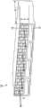
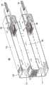
图4是根据本发明的优选实施例的呈腹部对腹部构型的机架安装件的一部分的示意性横截面。4 is a schematic cross-section of a portion of a rack mount in a belly-to-belly configuration in accordance with a preferred embodiment of the present invention.
图5A、图5B和图5C是根据本发明的优选实施例的呈堆叠构型的机架安装件的一部分的示意性横截面。5A, 5B, and 5C are schematic cross-sections of a portion of a rack mount in a stacked configuration in accordance with a preferred embodiment of the present invention.
图6示出了根据本发明的优选实施例的具有电连接器的呈腹部对腹部构型的机架安装件的一部分的示意性横截面。6 shows a schematic cross-section of a portion of a rack mount in a belly-to-belly configuration with electrical connectors in accordance with a preferred embodiment of the present invention.
图7是根据本发明的优选实施例的由金属片制成的散热模块的透视图。7 is a perspective view of a heat dissipation module made of sheet metal according to a preferred embodiment of the present invention.
图8是根据本发明的优选实施例的插座的透视图。8 is a perspective view of a socket according to a preferred embodiment of the present invention.
图9是根据本发明的优选实施例的收发器和插座连接器的透视图。9 is a perspective view of a transceiver and receptacle connector in accordance with a preferred embodiment of the present invention.
图10是插入到笼架中的插座连接器的后部透视图。Figure 10 is a rear perspective view of the receptacle connector inserted into the cage.
图11是插座连接器的前透视图。Figure 11 is a front perspective view of the receptacle connector.
图12是插座连接器的顶部分解图。Figure 12 is a top exploded view of the receptacle connector.
图13是插座连接器的后透视图。Figure 13 is a rear perspective view of the receptacle connector.
图14是替代插座连接器的后透视图。Figure 14 is a rear perspective view of an alternative receptacle connector.
图15是根据本发明的优选实施例的笼架的前透视图。15 is a front perspective view of a cage according to a preferred embodiment of the present invention.
图16是根据本发明的优选实施例的工具的透视图。16 is a perspective view of a tool according to a preferred embodiment of the present invention.
图17是根据本发明的优选实施例的具有鼓风机的插座的透视图。17 is a perspective view of a socket with a blower according to a preferred embodiment of the present invention.
图18是图17所示的鼓风机的透视图。FIG. 18 is a perspective view of the blower shown in FIG. 17 .
图19是插座的透视截面图。Figure 19 is a perspective cross-sectional view of the socket.
图20是图19所示的插座的侧视截面图。FIG. 20 is a side cross-sectional view of the socket shown in FIG. 19 .
图21示出了现有技术的有源缆线。Figure 21 shows a prior art active cable.
图22是已知插座的透视截面图。Figure 22 is a perspective cross-sectional view of a known socket.
图23是图22所示的已知插座的后透视图。FIG. 23 is a rear perspective view of the known socket shown in FIG. 22. FIG.
图24是图22所示的已知插座的侧视截面图。FIG. 24 is a side cross-sectional view of the known socket shown in FIG. 22 .
图25是具有散热器的插座的透视截面图。25 is a perspective cross-sectional view of a socket with a heat sink.
图26是具有传热翅片的插座的透视截面图。26 is a perspective cross-sectional view of a socket with heat transfer fins.
图27-图29是具有双层壁笼架的插座的透视图。27-29 are perspective views of a socket with a double wall cage.
具体实施方式Detailed ways
本发明的优选实施例在收发器与周围环境之间提供低阻抗热路径。通过强制对流空气流过散热器,提供向周围环境的热传递。散热器并入到可以安装到电子器件机架的散热模块的前挡板中。散热器可以为多个收发器提供冷却。这与散热器直接并入到收发器中的许多现有技术收发器形成对比。本发明的优选实施例有利地为密集地连接在电子器件机架中的大量收发器提供了优异的冷却。Preferred embodiments of the present invention provide a low impedance thermal path between the transceiver and the surrounding environment. Provides heat transfer to the surrounding environment by forced convective air flow through the heat sink. The heat sink is incorporated into the front bezel of the cooling module that can be mounted to the electronics rack. A heat sink can provide cooling for multiple transceivers. This is in contrast to many prior art transceivers where the heat sink is incorporated directly into the transceiver. Preferred embodiments of the present invention advantageously provide excellent cooling for a large number of transceivers that are densely connected in an electronics rack.
图1示出了机架安装件60的一部分。机架安装件60包括散热模块10、印刷电路板(PCB)50、散热器12、收发器30和缆线31。收发器30优选为光学收发器,并且缆线31优选为光缆。收发器30可以使用许多工业标准收发器格式中的一种,诸如QSFP+、PCIe、CXP、CFP、SFP等。具体地,收发器30可以满足SFF-8438(INF-8438i,修订版1.0,其通过整体引用结合在此)的要求。本发明的优选实施例不限于这些标准收发器格式,并且可以使用任何收发器,包括专用收发器或正在开发的收发器格式,诸如OSFP和微型OSFP。OSFP格式(即八路小形状因子封装)支持8个全双工通信信道。也就是说,所述格式有8个独立的传输信道和8个独立的接收信道。提供调制和/或接收功能的硅光子元件可以并入到这些收发器格式中的任何一种中;然而,这不是必需的。在图1中,收发器30被示出为与散热模块10中的它们相应的配插插槽11相邻。在操作中,收发器30可以插入到它们相应的插槽11中。机架安装件60不需要包括弹簧偏置的散热器。散热器12可以直接由散热模块10形成,而不是由定位在系统或机架的前挡板或平板后方的单独翅片结构形成。FIG. 1 shows a portion of a
为清楚起见,图1中所示的PCB 50没有装配任何电子部件;然而,实际上,PCB 50可以具有支持高速计算和通信的各种电子部件。PCB 50可以连接到多个散热模块10。每个模块10包括散热器12、笼架16以及用于收发器30的插槽11。以下更详细地描述散热模块10。一个或多个收发器30可以连接在散热模块10的插槽11中。在图1中,每个模块连接四个收发器30;然而,所述模块可以被配置成接受多于或少于四个收发器30。每个收发器30连接到缆线31,所述缆线提供PCB 50与数据网络中的一些其他元件之间的通信。如先前所提及的,收发器30优选为光学收发器,并且缆线31优选为包含一根或多根光纤的光缆。在图1中,四个散热模块10连接到PCB 50的顶部,并且四个散热模块10连接到PCB 50的底部。每个散热模块10能够接受四个收发器30,因此总计32个收发器可以连接到PCB 50,如图1所示。安装在PCB50上方的收发器30可以与PCB 50的顶部形成电连接,并且安装在PCB 50下方的收发器30可以与PCB 50的底部形成电连接。这种收发器构型被称为“腹部对腹部”,并且允许收发器30与PCB 50之间的短的电路径,以促进高带宽信号的传输,诸如10Gbps、28Gbps、56Gbps或甚至更高的带宽。For clarity, the
图2A示出了机架安装件60的一部分的端视图。在图2A中,为清楚起见,已经移除了收发器30。图2A示出了八个散热模块10。每个散热模块10具有用于四个收发器30的插槽11。每个插槽11由诸如金属的电导体包围,从而形成笼架16,所述笼架在位于相邻插槽11中的收发器30之间提供电磁屏蔽。PCB 50在图2A中并不清晰可见,但将位于上部一排与下部一排散热模块10之间,如图1所示。将安装到PCB 50以接受每个收发器30的连接器也未在图2A中示出。每个散热模块10具有散热器12,所述散热器包括具有空气通道的材料连接板,所述空气通道沿着从前向后的收发器插入方向完全贯穿散热器12。在图2A中,收发器插入方向延伸进入附图页面。与每个散热模块10相关联的散热器12为可以安装在插槽11中的全部四个收发器30提供冷却。收发器30本身不需要任何类型的翅片结构来将热散发到周围大气中,因为它们是通过传导到散热模块10的散热器12进行冷却的,并且可能强制空气沿着收发器插入方向吹过散热器12。可以在散热模块10之间提供电磁屏蔽(图2A中不可见)以减少杂散电磁辐射。FIG. 2A shows an end view of a portion of
图2B示出了具有散热模块10的机架安装件60的透视图。四个散热模块10位于PCB50的边缘上方,并且四个散热模块10位于PCB 50的边缘下方。散热模块10完全充满收发器30。缆线31连接到每个收发器30,并且每个收发器30可以具有拉环32以便容易地从散热模块10移除。凸缘15可以位于散热模块10的侧面上,以便将机架安装件60固定到电子器件机架18的侧面。图2B中示出了机架安装件60的代表性尺寸。机架安装件60可以与安装在19英寸机架中兼容。机架安装件60的高度可以是大约1.375英寸,并且所安装的收发器30的相对侧可以分开大约0.582英寸。这些尺寸与占据1U机架高度(1U=1机架单位=1.75”高)的散热模块10兼容。这些值仅是示例性的,并且所述尺寸可以根据需要进行调整以最佳地适合预期的应用。在实践中,这些机架安装件60中的许多安装件可以在电子器件机架中一个在另一个之上地堆叠。FIG. 2B shows a perspective view of rack mount 60 with
图3示出了单个散热模块10。散热模块10包括用于四个收发器30的插槽11和散热器12。插槽11可以包括闩锁特征(图3中未示出),所述闩锁特征有助于将插入式收发器30固定在适当位置。插槽11还可以包括柔性构件(图3中未示出),所述柔性构件轻轻地抵靠收发器30的侧面滑动以提供电磁屏蔽。散热器12包括材料连接板,以便为流过散热器12的空气的对流热传递提供大的表面积。在图3中,空气被描绘为沿方向A流出散热器12;然而,空气方向可以反转,即从前向后的收发器插入方向而不是如图所示的从后向前。风扇(图3中未示出)可以安装在散热模块10的正面、背面或侧面上,但这不是必需的。风扇可以安装在支撑散热模块10的电子器件机架(图3中未示出)中的其他位置。代替风扇,风管可以将强制空气带到电子器件机架。风扇或风管然后可以抽吸或强制空气沿着方向A或沿着收发器插入方向(与方向A180度相反)穿过散热器12。散热器12的连接板结构(webbing)可以被设计成使得其在散热器12的与插槽11相邻的区域中较厚,以便为散热器12的离插槽11较远的区域提供增强的导热性。图3中示出了六角形连接板图案;然而,连接板图案可以采取许多形式,诸如正方形、矩形、菱形、三角形、蛇形等。连接板图案也不必是规则图案,而是可以具有随机结构。散热器12提供了收发器30与对流表面区域之间的对流热传递的大的表面积和低阻抗传导路径。FIG. 3 shows a
散热模块10可以由金属挤出件或金属片制成。散热模块10可以由铝、铜、钢或这些材料的某种复合材料制成;然而,可以使用具有高电导率和热导率的任何材料。可以将涂层或表面处理应用于形成散热模块10的材料。导电性是重要的,因为散热器12可以帮助提供电磁屏蔽,以减少可以填充电机架的许多收发器30之间的电磁干扰(EMI)并且将所述机架外部的杂散EMI减少到可接受水平。为了提供足够的EMI屏蔽,散热器12的连接板结构之间的间隙应当小于辐射电磁能谱中所关注的最短波长的四分之一。对于以28Gbps进行操作的系统,所发射的主要EMI高达14GHz的频率,因此连接板元件之间的间隙可能为大约5mm或更小。对于所关注的频率较高的单元,所述间隙可以成比例地减小以实现类似的屏蔽水平。散热器12的深度d应当足以完全覆盖进入PCB 50的电连接,以提供有效的EMI屏蔽并提供足够的热传递。热建模表明,深度d优选地在20mm与60mm之间,但可以使用更短和更长的深度。也可以选择散热器12的高度h以提供足够的热传递以及紧凑的设计,使得图2A所示的腹部对腹部收发器构型可以安装在1U(1U=1机架单位=1.75”高)机架开口中。热建模表明,大约18mm的高度h应当提供足够的散热并且适配在1U机架开口内。例如,如果系统被设计成适配在2U机架开口中或适应呈不同构型的不同连接器或收发器尺寸,则可以使用更小或更大的高度h。The
图4示出了具有腹部对腹部构型的机架安装件60。上部连接器20a和下部连接器20b分别安装到PCB 50的顶部和底部。上部连接器20a提供上部收发器30a与PCB 50之间的电路径。类似地,下部连接器20b提供下部收发器30b与PCB 50之间的电路径。这些电路径可以使用一个或多个中心导体,所述一个或多个中心导体由电接地屏蔽件尽可能多地包围,以使沿着电连接器传送的高带宽信号的传输最大化并且使所述信号的失真最小化。上部收发器30a和下部收发器30b都是可插拔的,并且可以与它们相应的电连接器20a、20b配插和解除配插。上部缆线31a和下部缆线31b分别附连到上部收发器30a和下部收发器30b。这些缆线31a、31b传送和/或接收数据。FIG. 4 shows a
图4中还示出了两个弹簧14a、14b。弹簧14a、14b确保散热器12a、12b与作为主要发热部件的收发器30a、30b之间的牢固物理接触。弹簧14a、14b强制上部收发器30a和下部收发器30b抵靠它们相应的散热器12a、12b。这确保了收发器30a、30b与散热器12a、12b之间的低阻抗热路径,从而使收发器30a、30b的工作温度最小化。通常希望在尽可能接近室温的温度下操作收发器30a、30b。工作温度高于周围数据中心环境等于或低于30℃通常是可以接受的。热建模已经表明,图4所示的设计提供的散热远远超过了这个要求。所述建模表明,对于来自每个收发器30a、30b的5瓦热负载,收发器工作温度可以为高于周围大约6℃。提供更好的冷却和更低的收发器工作温度有利地增加了上部收发器30a和下部收发器30b中的任何激光二极管的工作寿命。虽然弹簧14a、14b在图4中被示出为板簧,但弹簧14a、14b可以采取多种形式,或者收发器30a、30b与散热器12a、12b之间的力可以由确保收发器30a、30b与散热器12a、12b之间的牢固物理接触的某种其他机构来提供。Also shown in FIG. 4 are two
图4中所示的腹部对腹部构型的优点在于,上部收发器30a和下部收发器30b都定位成与PCB 50相邻,使得收发器30a、30b与PCB 50之间的电路径较短。这允许以最小损失和干扰传输高带宽信号。然而,可以使用其他合适的构型。尽管上部连接器20a和下部连接器20b被示出为PCB安装板连接器,但连接器20、20b也可以是包括如图8所示的缆线连接器的缆线连接器。An advantage of the belly to belly configuration shown in FIG. 4 is that both the
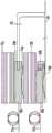
图5A-5C示出了替代的堆叠构型。在这些堆叠构型中,下部收发器30b与PCB 50相邻,并且上部收发器30a在下部收发器30b上方定位得离PCB 50较远。上部收发器30a和下部收发器30b分别连接到上部缆线31a和下部缆线31b。5A-5C illustrate alternative stacking configurations. In these stacked configurations, the
如图5A和图5B所示,下部连接器20b可以与图4中的下部连接器20b相同或类似,在所述图中,下部连接器20b直接连接到PCB 50。在图5A中,下部散热器12b位于下部收发器30b上方,所述下部散热器用于散发在下部收发器30b中产生的热。下部弹簧14b强制下部收发器30b抵靠下部散热器12b,从而确保它们之间的低阻抗热路径。上部弹簧14a定位在下部散热器12b与上部收发器30a之间,所述上部弹簧可以与下部弹簧14b相同或不同。上部弹簧14a也可以定位成使得其完全容纳在散热模块10中。上部弹簧14a强制上部收发器30a抵靠上部散热器12a,从而确保它们之间的低阻抗热路径。上部散热器12a用于散发在上部收发器30a中产生的热。上部连接器20a与上部收发器30a配插。跨越缆线22在上部连接器20a与PCB 50之间提供电路径。缆线22可以是任何合适的屏蔽电连接件,包括一个或多个同轴电缆或双轴缆线。缆线22可以是刚性的、半刚性的或柔性的。优选地使用柔性双轴缆线、即双股缆线,因为它容易地允许差分高速电信号的传播并且可以容易地以最小的损失和失真被路由到PCB 50上的任何位置。缆线22可以跨越PCB 50,如共同转让的美国临时专利申请62/131,989中所描述的,所述专利申请通过整体引用结合在此。堆叠构型的优点是,所有的高速电连接都可以在PCB 50的单侧上进行。此外,PCB 50上的部件高度可以是腹部对腹部构型中可用的高度的大约两倍。这个优选实施例的另一个优点在于,上部散热器和下部散热器12b可以在单个挤出步骤中整体形成。As shown in FIGS. 5A and 5B , the
在图5B和图5C中,散热模块10包括单个散热器12。下部弹簧14b强制下部收发器30b抵靠散热器12,从而确保它们之间的低阻抗热路径,并且上部弹簧14a强制上部收发器30a抵靠散热器12,从而确保它们之间的低阻抗热路径,所述上部弹簧可以与下部弹簧14b相同或不同。在图5B中,下部连接器20b直接连接到PCB 50,并且上部连接器20a通过缆线22连接到PCB 50。在图5C中,下部连接器20b通过缆线22b连接到PCB 50,并且上部连接器20a通过缆线22a连接到PCB 50。还可能的是,下部连接器20b包括直接连接到PCB 50(如图5B所示)的一些电路径,以及通过缆线22b连接到PCB 50(如图5C所示)的一些电路径。In FIGS. 5B and 5C , the
图6示出了具有腹部对腹部构型的机架安装件60的一部分,其中连接器20a、20b附连到散热器12a、12b。这个优选实施例类似于图4所示的实施例,因此将仅描述这两个图之间的差异。图4所示的优选实施例与图6所示的优选实施例之间的差异在于连接器20a、20b的安装。在图4中,连接器20a、20b直接连接到PCB 50。如以上所提及的,这具有在连接器20a、20b与PCB 50之间提供短的刚性电路径的优点。然而,这种固定的刚性安装可能导致不利的公差累积。在一些情况下,当收发器30a、30b同时与连接器20a、20b配插时,可能难以强制所述收发器与散热器12a、12b齐平。图6所示的优选实施例解决了这个问题。在图6中,上部连接器20a和下部连接器20b分别安装在上部散热器12a和下部散热器12b上。上部连接器20a和下部连接器20b可以安装到散热器12a、12b的表面19a、19b,使得上部连接器20a和下部连接器20b可以在平行于散热器12a、12b的表面19a、19b的方向上移动。类似地,连接器20a、20b可以利用(例如但不限于)导向件或凹槽安装在散热模块10的长度内,其方式使得连接器20a、20b可以在平行于或基本上平行于散热器12a、12b的表面19a、19b的方向上自由移动。然而,图6中的连接器20a、20b在与收发器30a、30b的插入方向平行或基本上平行的方向上受限,所述插入方向垂直于或基本上垂直于表面19a、19b。这种安装构型允许连接器20a、20b在垂直于或基本上垂直于收发器配插方向的方向上浮动,但是在配插方向上被刚性地限制住。因为连接器20a、20b可以沿竖直方向浮动,所以弹簧14a、14b可以强制收发器30a、30b抵靠它们相应的散热器12a、12b,同时几乎不用考虑收发器30a、30b与散热器12a、12b之间由于公差叠加而可能缺乏接触。因为在这个优选实施例中,上部连接器和下部连接器相对于PCB 50的位置不再是固定的,所以可以使用类似于关于图5C所描述的那些缆线的缆线22a、22b来提供连接器20a、20b与PCB 50之间的电路径。还可能的是,连接器20a、20b可以包括直接连接到PCB 50(如图4所示)的一些电路径,以及通过缆线22a、22b连接到PCB 50(如图6所示)的一些电路径。Figure 6 shows a portion of a
其他构型是可能的。图1、图2、图4和图6中所示的腹部对腹部构型以及图5A-5C中所示的堆叠构型都具有收发器30、30a、30b的平行于或基本上平行于PCB 50的平面的主表面,即具有最大表面积的表面。这不是必需的。收发器30、30a、30b的主表面可以在制造公差内垂直于或基本上垂直于PCB平面定向。在这种情况下,可以将跨越型电连接件布置到PCB50,如共同转让的美国专利申请号62/136,059、62/107,671和14/845,990中所描述的,所述专利申请各自通过整体引用结合在此。在这些垂直构型中,可以将散热器设置在收发器的至少一个主表面附近。在堆叠构型中,上部收发器30a和上部散热器12a的位置可以颠倒,使得下部散热器12b和上部散热器12a彼此相邻。根据PCB组件的布局,这些不同的构型可以在任何系统中混合和匹配,以实现最佳布局,从而针对通信网络中所有信道,最大化信号完整性、热性能、密度或其他度量,或它们的任何组合。Other configurations are possible. The belly-to-belly configurations shown in Figures 1, 2, 4 and 6 and the stacked configurations shown in Figures 5A-5C all have
如先前所提及的,散热模块10可以由金属片形成。图7示出了金属片散热模块10。整体布局类似于针对图3中所示的挤出散热模块10所示的布局。散热模块10具有多个插槽11以接受收发器30。笼架16包围每个插槽11,以使收发器30与任何电路之间的EMI最小化。均热器13与笼架16的顶部相邻。均热器13可以由实心金属块形成并且用于将由收发器30(图7中未示出)产生的热分配到散热器12。散热器12可以由弯曲且切割的金属片连接板形成。在图7中,所述连接板被示出为具有正方形开口以允许空气穿过散热器12。如先前所描述的,可以使用其他形状的空气通道。散热模块10具有多个连接到PCB(图7中未示出)的安装脚17。金属片散热模块10可以以上述优选实施例中的任何一个来安排。金属片形成的散热模块10的优点在于,它可以比挤出的散热模块10更便宜且更容易制造。As previously mentioned, the
可以使用电收发器来代替光学收发器。也可以使用独立的发射器和/或接收器来代替收发器。系统中各种部件的位置也可以变化。例如,图4示出了上部收发器30a和下部收发器30b的基本上与PCB 50的端部平齐的非配插端部。这不是必需的。收发器可以延伸超过PCB 50的端部或者凹入,使得PCB 50的端部延伸超过收发器端部。部件位置通常用上部部件和下部部件来描述。应当理解的是,这些术语与PCB安装取向有关,并且可以根据取向进行左/右交换或替换。Instead of optical transceivers, electrical transceivers can be used. Instead of transceivers, separate transmitters and/or receivers may also be used. The location of various components in the system can also vary. For example, FIG. 4 shows the non-mating ends of the
本发明的优选实施例还包括插座,所述插座可以接收一个或多个收发器并且包括笼架以及位于笼架中的电连接器。电连接器可以包括跨越PCB到达PCB上的不同位置的高速缆线和低速缆线。使用低速缆线在多插槽笼架中的插槽之间提供附加的空间,这允许收发器之间增加的空气流动,从而改善收发器的冷却和热管理。电连接器可以插入到笼架的后部中。电连接器可以包括与笼架中的闩锁插槽接合的闩锁。鼓风机可以用来改善冷却。可以在额外的空间中设置散热器(具有或不具有强制风)以改善冷却。可以在额外的空间中设置流体冷却式散热器(诸如热导管)以进一步改善冷却。Preferred embodiments of the present invention also include a socket that can receive one or more transceivers and includes a cage and electrical connectors located in the cage. The electrical connectors may include high-speed and low-speed cables that span across the PCB to different locations on the PCB. The use of low-speed cables provides additional space between the slots in the multi-slot cage, which allows for increased air flow between the transceivers, improving transceiver cooling and thermal management. Electrical connectors can be inserted into the rear of the cage. The electrical connector may include a latch that engages a latch slot in the cage. Blowers can be used to improve cooling. Radiators (with or without forced air) can be placed in the extra space to improve cooling. Fluid-cooled heat sinks, such as heat pipes, can be provided in the additional space to further improve cooling.
可以将电连接器移除工具插入到笼架组件的前部中,以便从笼架移除电连接器。An electrical connector removal tool can be inserted into the front of the cage assembly to remove the electrical connector from the cage.
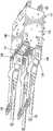
图8示出了根据本发明的优选实施例的插座100。插座100包括具有安排成两排的四个插槽111的笼架116。每个插槽111可以接受一个收发器130。图8示出了与三个收发器130配插的三个插槽111和一个空的插槽111。笼架116的底部包括安装脚117,所述安装脚允许将插座100安装到PCB(图8中未示出)。插座100可以包括位于上部插槽与下部插槽111之间的任选的面板119。面板119可以包括允许空气在插座连接器120(图19)之间并且在缆线122上方、通过通路107(图19)流过面板119的多个开口或排气孔。换句话说,开口或排气孔流体连接到由插座连接器120之间的通路107限定的开口。通路107可以从第一端延伸到第二端并且可以定位成与两个插座连接器中的一个相邻。空气还可以在缆线122上方、在插座连接器120之间流过通路107并且流过面板119。在无强制风系统中,热可以从通路107通过第一端和第二端逸出,或者通过面板119开口和位于插座连接器120之间的第二端开口逸出。换句话说,通路中的热可以平行于收发器配插方向行进穿过通路107并且通过第一端和第二端逸出。通路107可定位成邻近且平行于插槽111中的一个,定位在两个相邻的插槽111之间并且平行于所述插槽,或者定位成邻近且平行于至少一个插座连接器120。笼架116可以包括围绕其周边的多个电磁干扰(EMI)屏蔽件118,以限制辐射的EM场。笼架116组件的高度可以与将笼架116和附连的PCB安装在1U机架开口内兼容。插座100可以安装在电子器件机架中。插座100包括从笼架116的后部延伸的缆线122。缆线122可以在插座100与PCB之间传送高速信号和低速信号。Figure 8 shows a
收发器130包括向和从收发器130传送信号的缆线131。收发器130可以包括拉片132,所述拉片可以用于将收发器130从插座130移除。缆线131跨越PCB。使用跨越缆线用于高速信号的益处在共同转让的美国专利申请号62/136,059、62/107,671和14/845,990中进行描述。The
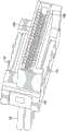
图9示出了收发器130和插座连接器120。插座连接器120位于图8所示的笼架116内。收发器130通过以下方式与插座100配插:将收发器130插入到插座100中使得边缘卡134插入到插座连接器120中。缆线122从插座连接器120的后部延伸。缆线122可以端接到插座连接器120中的触点并且端接到PCB,从而在插座连接器120与PCB之间形成电路径。收发器130可以使用许多工业标准收发器格式中的一种,诸如QSFP+、PCIe、CXP、CFP、SFP等。具体地,收发器30可以满足SFF-8438(INF-8438i,修订版1.0)的要求。FIG. 9 shows
图10示出了插入到笼架116后部的插座连接器120。图11-13示出了插座连接器120。插座包括夹具128、引线架124和壳体125。壳体125可以由任何合适的电绝缘材料制成,诸如模制塑料。引线架124插入到壳体120中并且通过夹具128保持在适当位置。引线架124包括缆线122和触点123a、123b上的包覆模制件。上部触点123a与收发器130的边缘卡134的顶部上的电连接点匹配,并且下部触点123b与收发器130的边缘卡134的底部上的电连接点匹配。可以使用任何数量的触点123a、123b。还可能的是,仅使用上部触点123a或下部触点123b。FIG. 10 shows the
夹具128包括闩锁121。当插座连接器120插入到笼架116中时,闩锁121与笼架116中的闩锁插槽103接合。尽管图11示出了顶部上的两个闩锁121和底部上的两个闩锁121,但可以使用任何数量和任何位置的闩锁121。夹具128还可以包括开口129,当夹具128连接到壳体125时,所述开口与壳体125上的凸起126接合。夹具128可以由冲压和成形的金属片制成。夹具121可以包括用于缆线122的一个或多个开口。Clamp 128 includes
如图13所示,缆线122可以包括高速缆线122a和低速缆线122b。可以使用任何数量的高速缆线122a和低速缆线122b。高速缆线122a可以传送例如超过10Gbps的高带宽信号,并且可以包括例如双股缆线、同轴电缆、三同轴电缆,或者某种其他合适的电传输线。在一些应用中,高速是至少25吉比特/秒的数据传输速度,并且低速是小于25吉比特/秒的数据传输速度。低速缆线122b可以传送例如控制信号和电力,并且可以包括例如不具有接地屏蔽件的绝缘电线。缆线122a、122b的一端可以端接到相应的触点123a、123b,并且缆线的另一端可以端接到PCB。如果缆线122a是双股缆线,则双股缆线的两个中心导体可以端接到相邻的信号触点并且屏蔽件可以连接到接地触点。As shown in FIG. 13, the
图14示出了包括PCB组件(PCBA)127的替代插座连接器120。PCBA 127可以包括提供信号和/或电源调节和/或滤波的电部件。因为电源和控制信号将具有较少的电噪声,所以PCBA 127可以改善收发器130的性能并简化其设计。FIG. 14 shows an
图15、图19和图20示出了笼架116。笼架116可以包括可以用于将笼架116安装到PCB(PCB在图15中未示出)的安装脚117。安装脚117可以是适合压配安装的“针眼”型。插座连接器120不需要具有用于将插座连接器120安装到PCB的任何安装脚(包括例如压配脚、通孔针、表面安装脚等)。笼架116包括限定插槽111的壁106。尽管图15中示出了呈2x2阵列的四个插槽111,但笼架116可以包括任意数量的呈任何安排的插槽111。例如,笼架116可以具有以1x2阵列(沿着基板水平地间隔开)或以2x1阵列(相对于基板竖直地堆叠)安排的两个插槽。壁106可以包括闩锁104,当收发器130与插座100配插时,所述闩锁接合收发器130。类似于图4-6中的弹簧14a、14b,每个插槽111可以包括一个或多个弹簧,以便将收发器130压向通道107,从而确保收发器130与通道107之间的牢固物理接触。笼架116可以以任何合适的方式制成,包括由冲压和成形的金属制成。
如图19所示,笼架116还包括提供空气流动路径的通道107。通道107允许空气在插座100的前部(收发器130可以插入所述前部中)与插座100的后部(插座连接器120插入所述后部中)之间流动。当收发器130插入到插座中的顶部插槽和底部插槽111时,空气可以在顶部收发器与底部收发器130之间流动并且从插座的前部到后部(或从后部到前部)流动,从而冷却产生热的收发器130。通道107的前部可以包括面板119(面板119在图15中未示出,但是在图19和图20中示出),并且通道107的后部可以是未覆盖的。通过不使用插片,可以将插座连接器120安排成不阻挡或最小化阻止完全穿过通道107的两个相对端的空气流动,使得空气流体穿过面板119、穿过通道107并且在插座连接器120之间穿过。缆线122可以被安排成不阻挡或阻止空气流动。除了不阻挡空气流动之外,缆线122提供比已知插座205中使用插片222的情况下更好的信号完整性。因此,可以提供从插座100的前部到后部(或如上所述从后部到前部)的空气流动路径。As shown in Figure 19, the
代替具有如图15、图19和图20所示的开放通道107,通道107可以包括类似于图26所示的翅片171的传热翅片,所述传热翅片从与收发器130相邻的壁延伸到通道107内部或者可以包括散热器,诸如图25中所示的散热器162。这种六边形图案可以提供从插座100的前部到后部的多个空气路径。连接板结构可以具有恒定的厚度或者可以具有可变的厚度。例如,连接板结构的顶部和底部可以较厚并且在中部附近较薄。Instead of having
笼架116可以包括位于通道107中的光导管105。如图15所示,每个通道107可以包括两个光导管105。光导管105可以将来自PCB上的LED的光传送到插座100前部。光导管105的横截面积优选地小于通道107的总横截面积的15%。例如,通道107可以具有450mm2的横截面积,并且光导管105可以具有25mm2的横截面积。如果每个通道107具有两个光导管105,则两个光导管的总横截面积为50mm2,这是通道107的总横截面积的约11%。
图15的笼架116可以用图5B和图5C所示的堆叠构型来使用。如果插座连接器120包括缆线122,则笼架116可以用于图5C所示的堆叠构型。如果底部插座连接器120提供通向PCB的直接电路径,则笼架116可以用于图5B所示的堆叠构型。其他构型也是可能的。例如,如果底部插座连接器120包括缆线122以及通向PCB的直接电路径,则笼架116可以用于作为图5B和图5C的组合的堆叠构型。The
图25示出了具有笼架166的插座100。笼架166类似于笼架116,但是包括位于通道107中的散热器162并且是双层壁的。散热器162沿着通道107延伸。通道107的前部开口可以由面板119覆盖,并且通道的后部开口可以由面板169覆盖。并非必须使用与散热器162分开的面板119、169。面板119、169可以是散热器162的一部分。散热器162可以类似于图3所示的散热器12,具有例如六边形连接板结构。其他连接板结构图案也是可能的。散热器162限定通道107的前部与后部之间的空气流动路径。FIG. 25 shows the
笼架166包括安排成2x2阵列的四个插槽111。也可以使用其他数量和安排的插槽111。两列插槽111由限定这两列插槽111之间的通道的内部双层壁分开。内部双层壁之间的通道的开口由具有孔的面板168覆盖。面板168可以与面板119分开,或者可以连接到面板119而作为单个整体。面板168中的孔的尺寸和形状可以与面板119中的孔相同或可以不同。在笼架166的顶部中沿着内部双层壁之间的通道安排了孔167。孔167的尺寸和形状可以与面板168中的孔的尺寸和形状相同或可以不同。
如图25所示,笼架166的外壁可以是双层壁。图25中仅示出一个外部双层壁,因为图25是截面图。与内部双层壁一样,外部双层壁可以由具有孔的面板168覆盖,并且可以包括沿着笼架166的顶部的孔167。面板168中的孔可以流体连接到相邻插槽111之间的空腔。所述空腔可以从面板168、穿过笼架166并延伸到可选的后部面板169。可替代地或另外,面板168中的孔可以流体连接到孔167。外部双层壁可以包括与通道107相邻的孔167(图25中未示出,但在图27中示出),以提供穿过外部双层壁且位于外双层壁底部处的空气流动,进而提供位于外部双层壁底部处的空气流动。内部双层壁可以包括类似地安排的孔。尽管在图25中未示出,但可以将顶部外部双层壁和底部外部双层壁添加到笼架166,使得每个插槽111在四个侧面上具有通道。As shown in Figure 25, the outer walls of the
图26示出了具有笼架116的插座100。图26中的笼架116包括延伸到通道107中的翅片171。翅片171可以帮助将来自插槽111中的收发器的热传递到通道107。可以使用任何数量、尺寸和形状的翅片171。图26中的面板119包括光导管105延伸穿过的孔。光导管105的端部可以与插座100的前部齐平或基本上齐平。FIG. 26 shows the
图27-29示出了具有笼架166的插座100。图27-29中的笼架166类似于图25中所示的笼架166,但不具有散热器162。在图27中,笼架166包括面板119、168,并且在图28中,笼架166不具有面板119、168。图28示出了位于内部双层壁和外部双层壁中的光导管105。尽管图28示出了四个光导管105(两个位于一个外部双层壁中并且两个位于内部双层壁中),但可以使用任何数量和任何安排的光导管105。笼架166包括两个外部双层壁和一个内部双层壁。笼架166可以包括延伸过笼架166的顶部和底部的双层壁。可以与不同阵列的插槽111一起使用不同安排的双层壁。例如,2x3阵列的插槽111可以包括两个内部双层壁和两个外部双层壁。如图28所示,内部双层壁和外部双层壁都可以包括与通道107相邻的孔167。双层壁还可以包括在双层壁底部附近的孔167。笼架166的顶部还可以包括在由双层壁限定的通道之上的孔167。尽管图28中未示出,但通道107也可以包括类似于图26中的翅片171的翅片。27-29 illustrate the
图29示出了两个后部面板169。取决于插槽111的安排,可以使用任何数量和任何安排的面板169。孔的尺寸和形状可以与面板119、168中的孔的尺寸和形状相同或可以不同。Figure 29 shows two
空气可以被强制穿过通道107以增加对收发器130的冷却。如果插座100被包括在电子器件机架中的机架安装件上,则安装在机架安装件上或电子器件机架中的风扇可以强制空气穿过通道107。还可能的是,如图17所示,接收器100包括附连到笼架116的鼓风机140。图18示出了鼓风机140。鼓风机140包括引导吹送空气的引导件141。如图18所示,鼓风机140可以沿方向C接收空气并且沿方向D吹送空气穿过引导件141、进入笼架116的外壁中的孔。引导件141的三个指状物中的每一个都可以将空气导入连接到顶部面板119a、中部面板119b和底部面板119c的通道107中的一个。以这种方式,鼓风机140可以吹送周围空气穿过通道107并且吹过收发器130。鼓风机140还可以沿相反方向、从插座100内向外部周围空气吹送空气。如果通道107中存在散热器,则也可以使用可能具有管道的鼓风机140。可以使用任何合适的鼓风机。鼓风机140可以是具有旋转叶片的30-mm直径的风扇、压电致动风扇、电晕(离子)风扇等。代替安装到笼架116的外部,可以将鼓风机140安装在一个或多个通道107内。Air may be forced through
除了鼓风机140之外,图17还示出了插座100的其他可能的安排。例如,插槽111可以安排成2x4阵列,使得插座可以接收总计八个收发器130。代替单个面板119,插座100可以包括顶部面板119a、中部面板119b和底部面板119c。每个面板119a、119b和119c覆盖允许空气从插座100的前部到后部(或从后部到前部)流动的单独通道。这种安排类似于图5A中所示的堆叠安排,但是具有位于PCB 50与下部收发器30b和下部连接器20b之间的附加散热器。在这种安排中,下部连接器20b将包括缆线22b,以提供来自下部连接器20b和PCB 50的电路径。In addition to the
如果图8和图17中所示的笼架116的高度相同,则图17中的插槽111比图8中的插槽111更靠近在一起。If the heights of the
所述笼架可以包括充有液体的热导管,所述热导管促进远离与笼架配插的收发器的热传递。热导管可以用于散布来自局部热源、诸如收发器130的光学引擎的热。例如,图7中所示的均热器13可以包括热导管,以促进插槽11中的收发器与散热器12之间的热传递。热导管允许减少均热器的厚度,从而减少重量并增加散热器的可用面积。The cage may include liquid-filled heat pipes that facilitate heat transfer away from the transceivers mated with the cage. Heat pipes may be used to distribute heat from localized heat sources, such as the optical engine of
图16示出了插座-连接器移除工具190。为了移除插座连接器120,将插座-连接器移除工具190从笼架116的前侧插入到插槽111中,如例如图26所示。上部斜面191a和下部斜面191b使夹具128弹性变形,使得闩锁121与闩锁插槽103脱离接合。继续将插座-连接器移除工具190推入插槽111中将会使插座连接器120从笼架116的后部推出。利用简单的工具修复或更换插座连接器120的能力提供了灵活性并且易于系统维护和调试。不需要对任何连接解除焊接来移除插座连接器120,并且因此在移除操作过程中几乎不可能存在无意的损坏。FIG. 16 shows the receptacle-
应理解的是,以上描述仅用于阐述本发明。在不脱离本发明的情况下,本领域技术人员可以设计出各种替代方案和修改。因此,本发明旨在涵盖落入所附权利要求书范围内的所有此类替代方案、修改和变化。It is to be understood that the above description is only intended to illustrate the present invention. Various alternatives and modifications can be devised by those skilled in the art without departing from the invention. Accordingly, the present invention is intended to cover all such alternatives, modifications and variations as fall within the scope of the appended claims.
Claims (16)
Applications Claiming Priority (7)
| Application Number | Priority Date | Filing Date | Title |
|---|---|---|---|
| US201562216609P | 2015-09-10 | 2015-09-10 | |
| US62/216,609 | 2015-09-10 | ||
| US201662341650P | 2016-05-26 | 2016-05-26 | |
| US62/341,650 | 2016-05-26 | ||
| US201662350368P | 2016-06-15 | 2016-06-15 | |
| US62/350,368 | 2016-06-15 | ||
| CN201680052852.2ACN108028494B (en) | 2015-09-10 | 2016-09-09 | Rack mount equipment with high heat dissipation modules and transceiver sockets with increased cooling |
Related Parent Applications (1)
| Application Number | Title | Priority Date | Filing Date |
|---|---|---|---|
| CN201680052852.2ADivisionCN108028494B (en) | 2015-09-10 | 2016-09-09 | Rack mount equipment with high heat dissipation modules and transceiver sockets with increased cooling |
Publications (1)
| Publication Number | Publication Date |
|---|---|
| CN110632717Atrue CN110632717A (en) | 2019-12-31 |
Family
ID=58237370
Family Applications (8)
| Application Number | Title | Priority Date | Filing Date |
|---|---|---|---|
| CN201910972158.8APendingCN110632717A (en) | 2015-09-10 | 2016-09-09 | Rack mount equipment with high heat dissipation modules and transceiver sockets with increased cooling |
| CN201910972282.4AActiveCN110531474B (en) | 2015-09-10 | 2016-09-09 | Rack-mounted equipment with high heat dissipation modules and transceiver jacks with increased cooling |
| CN201910971826.5AActiveCN110596831B (en) | 2015-09-10 | 2016-09-09 | Rack-mounted equipment with high heat dissipation modules and transceiver jacks with increased cooling |
| CN201910972149.9APendingCN110531473A (en) | 2015-09-10 | 2016-09-09 | Rack installing type equipment with high heat-dissipation module and the transceiver receptacle with increased cooling |
| CN201910972331.4APendingCN110673277A (en) | 2015-09-10 | 2016-09-09 | Rack mount equipment with high heat dissipation modules and transceiver sockets with increased cooling |
| CN201910971907.5APendingCN110632708A (en) | 2015-09-10 | 2016-09-09 | Rack mount equipment with high heat dissipation modules and transceiver sockets with increased cooling |
| CN201910971918.3AActiveCN110632716B (en) | 2015-09-10 | 2016-09-09 | Rack-mounted equipment with high heat dissipation modules and transceiver jacks with increased cooling |
| CN201680052852.2AActiveCN108028494B (en) | 2015-09-10 | 2016-09-09 | Rack mount equipment with high heat dissipation modules and transceiver sockets with increased cooling |
Family Applications After (7)
| Application Number | Title | Priority Date | Filing Date |
|---|---|---|---|
| CN201910972282.4AActiveCN110531474B (en) | 2015-09-10 | 2016-09-09 | Rack-mounted equipment with high heat dissipation modules and transceiver jacks with increased cooling |
| CN201910971826.5AActiveCN110596831B (en) | 2015-09-10 | 2016-09-09 | Rack-mounted equipment with high heat dissipation modules and transceiver jacks with increased cooling |
| CN201910972149.9APendingCN110531473A (en) | 2015-09-10 | 2016-09-09 | Rack installing type equipment with high heat-dissipation module and the transceiver receptacle with increased cooling |
| CN201910972331.4APendingCN110673277A (en) | 2015-09-10 | 2016-09-09 | Rack mount equipment with high heat dissipation modules and transceiver sockets with increased cooling |
| CN201910971907.5APendingCN110632708A (en) | 2015-09-10 | 2016-09-09 | Rack mount equipment with high heat dissipation modules and transceiver sockets with increased cooling |
| CN201910971918.3AActiveCN110632716B (en) | 2015-09-10 | 2016-09-09 | Rack-mounted equipment with high heat dissipation modules and transceiver jacks with increased cooling |
| CN201680052852.2AActiveCN108028494B (en) | 2015-09-10 | 2016-09-09 | Rack mount equipment with high heat dissipation modules and transceiver sockets with increased cooling |
Country Status (5)
| Country | Link |
|---|---|
| US (10) | US10114182B2 (en) |
| EP (1) | EP3347951A4 (en) |
| CN (8) | CN110632717A (en) |
| CA (1) | CA2997919C (en) |
| WO (1) | WO2017044825A1 (en) |
Families Citing this family (98)
| Publication number | Priority date | Publication date | Assignee | Title |
|---|---|---|---|---|
| US9240644B2 (en) | 2012-08-22 | 2016-01-19 | Amphenol Corporation | High-frequency electrical connector |
| US9685736B2 (en) | 2014-11-12 | 2017-06-20 | Amphenol Corporation | Very high speed, high density electrical interconnection system with impedance control in mating region |
| JP6495459B2 (en)* | 2015-01-27 | 2019-04-03 | モレックス エルエルシー | Plug module system |
| CN110632717A (en)* | 2015-09-10 | 2019-12-31 | 申泰公司 | Rack mount equipment with high heat dissipation modules and transceiver sockets with increased cooling |
| WO2017058232A1 (en)* | 2015-10-01 | 2017-04-06 | Hewlett Packard Enterprise Development Lp | Removable module |
| TWI746561B (en) | 2016-05-31 | 2021-11-21 | 美商安芬諾股份有限公司 | High performance cable termination |
| US9793667B1 (en)* | 2016-07-22 | 2017-10-17 | Arista Networks, Inc. | QSFP to OSFP module form factor adapter |
| CN110088985B (en) | 2016-10-19 | 2022-07-05 | 安费诺有限公司 | Flexible shield for ultra-high speed high density electrical interconnects |
| US10921536B2 (en)* | 2017-05-18 | 2021-02-16 | Arista Networks, Inc. | Heat sink for optical transceiver |
| US10446960B2 (en) | 2017-05-21 | 2019-10-15 | Foxconn Interconnect Technology Limited | Electrical connector assembly equipped with heat pipe and additional heat sink |
| WO2018226805A1 (en)* | 2017-06-07 | 2018-12-13 | Samtec, Inc. | Transceiver assembly array with fixed heatsink and floating transceivers |
| TWI828624B (en) | 2017-06-13 | 2024-01-11 | 美商山姆科技公司 | Electrical connector system and method using the same |
| US10555437B2 (en) | 2017-06-20 | 2020-02-04 | Foxconn Interconnect Technology Limited | Electrical connector assembly equipped with heat pipe and additional heat sink |
| US10644472B2 (en) | 2017-06-28 | 2020-05-05 | Mellanox Technologies, Ltd. | Cable adapter |
| US11289850B2 (en) | 2017-07-21 | 2022-03-29 | Samtec, Inc. | Electrical connector having latch |
| USD964291S1 (en) | 2017-07-21 | 2022-09-20 | Samtec, Inc. | Electrical connector |
| TWI788394B (en) | 2017-08-03 | 2023-01-01 | 美商安芬諾股份有限公司 | Cable assembly and method of manufacturing the same |
| KR102732353B1 (en) | 2017-10-24 | 2024-11-21 | 샘텍, 인코포레이티드 | Right angle electrical connectors and electrical contacts for right angle connectors |
| US10651606B2 (en) | 2017-11-11 | 2020-05-12 | Foxconn (Kunshan) Computer Connector Co., Ltd. | Receptacle connector equipped with cable instead of mounting to PCB |
| CN109787000B (en) | 2017-11-11 | 2021-11-19 | 富士康(昆山)电脑接插件有限公司 | Double-sided socket connector and electrical system thereof |
| CN110031940B (en)* | 2018-01-05 | 2021-01-19 | 台达电子工业股份有限公司 | Optical module plugging device |
| USD896183S1 (en) | 2018-01-08 | 2020-09-15 | Samtec, Inc. | Electrical cable connector |
| CN110133806A (en)* | 2018-02-09 | 2019-08-16 | 华为技术有限公司 | Optical module cage and communication equipment |
| US11169340B2 (en)* | 2018-03-21 | 2021-11-09 | Foxconn (Kunshan) Computer Connector Co., Ltd. | Interconnection system |
| US10665973B2 (en) | 2018-03-22 | 2020-05-26 | Amphenol Corporation | High density electrical connector |
| WO2019195319A1 (en) | 2018-04-02 | 2019-10-10 | Ardent Concepts, Inc. | Controlled-impedance compliant cable termination |
| US10559930B2 (en) | 2018-04-04 | 2020-02-11 | Foxconn (Kunshan) Computer Connector Co. Ltd | Interconnection system |
| CN110380285B (en) | 2018-04-12 | 2023-02-10 | 富加宜(美国)有限责任公司 | Top loading electronic connection system |
| CN210690881U (en) | 2018-04-18 | 2020-06-05 | 安费诺有限公司 | Cage assembly for electrical connector and electronic system |
| CN110391563A (en) | 2018-04-21 | 2019-10-29 | 富士康(昆山)电脑接插件有限公司 | Electric interconnection system |
| US10877232B1 (en) | 2018-05-02 | 2020-12-29 | Amazon Technologies, Inc. | Connector for multiple cabling arrangements |
| US10705309B2 (en)* | 2018-06-06 | 2020-07-07 | Mellanox Technologies, Ltd. | RF EMI reducing fiber cable assembly |
| US10581210B2 (en)* | 2018-07-30 | 2020-03-03 | Te Connectivity Corporation | Receptacle assembly having cabled receptacle connectors |
| US10476198B1 (en)* | 2018-07-30 | 2019-11-12 | Te Connectivity Corporation | Receptacle cage for stacked cabled receptacle connectors |
| CN115498453A (en)* | 2018-08-28 | 2022-12-20 | 泰科电子(上海)有限公司 | Receptacle Connectors and Connector Assemblies |
| US10797417B2 (en) | 2018-09-13 | 2020-10-06 | Amphenol Corporation | High performance stacked connector |
| CN208862209U (en) | 2018-09-26 | 2019-05-14 | 安费诺东亚电子科技(深圳)有限公司 | A connector and its applied PCB board |
| US11271348B1 (en)* | 2018-10-24 | 2022-03-08 | Amphenol Corporation | High performance electrical connector |
| JP2020088070A (en)* | 2018-11-20 | 2020-06-04 | 富士通株式会社 | Information processing device and board unit |
| US10931062B2 (en) | 2018-11-21 | 2021-02-23 | Amphenol Corporation | High-frequency electrical connector |
| CN109449685A (en)* | 2018-11-21 | 2019-03-08 | 绵阳昱丰电子科技有限公司 | A kind of hyper tape shielding has the open electric connector of water-proof function |
| US10788637B2 (en)* | 2018-12-21 | 2020-09-29 | Juniper Networks, Inc. | Apparatus, system, and method for dissipating heat emitted by individual communication modules via ganged heat exchangers |
| US11101611B2 (en) | 2019-01-25 | 2021-08-24 | Fci Usa Llc | I/O connector configured for cabled connection to the midboard |
| WO2020154507A1 (en)* | 2019-01-25 | 2020-07-30 | Fci Usa Llc | I/o connector configured for cable connection to a midboard |
| WO2020172395A1 (en) | 2019-02-22 | 2020-08-27 | Amphenol Corporation | High performance cable connector assembly |
| US10741954B1 (en) | 2019-03-17 | 2020-08-11 | Mellanox Technologies, Ltd. | Multi-form-factor connector |
| CN113296198A (en)* | 2020-02-21 | 2021-08-24 | 佑胜光电股份有限公司 | Optical transmission assembly, optical transceiver module and optical fiber cable module |
| US10873161B2 (en)* | 2019-05-06 | 2020-12-22 | Te Connectivity Corporation | Receptacle assembly having cabled receptacle connector |
| US10873160B2 (en) | 2019-05-06 | 2020-12-22 | Te Connectivity Corporation | Receptacle assembly having cabled receptacle connector |
| EP3780289A1 (en)* | 2019-08-16 | 2021-02-17 | TE Connectivity Belgium BVBA | Shielding housing for a detachable fully shielded internal cable assembly |
| CN114788097A (en) | 2019-09-19 | 2022-07-22 | 安费诺有限公司 | High speed electronic system with midplane cable connector |
| WO2021061916A1 (en) | 2019-09-27 | 2021-04-01 | Fci Usa Llc | High performance stacked connector |
| JP2022548080A (en)* | 2019-10-04 | 2022-11-16 | モレックス エルエルシー | Method and device for protecting multi-level multi-port connector assemblies from electromagnetic interference |
| US11169330B2 (en) | 2019-10-24 | 2021-11-09 | Mellanox Technologies Tlv Ltd. | Wavelength-splitting optical cable |
| US11112573B2 (en)* | 2019-11-01 | 2021-09-07 | Ciena Corporation | Cooling multiple high-density network pluggable optical modules using a shared heat exchanger |
| US12244084B2 (en) | 2019-11-12 | 2025-03-04 | Samtec, Inc. | Interconnection system, case assembly, electrical connector, assembly and connector assembly using detachable, cabled front-panel connector |
| US11357132B2 (en) | 2020-01-23 | 2022-06-07 | Cisco Technology, Inc. | Air cooled cage design |
| TWI887339B (en) | 2020-01-27 | 2025-06-21 | 美商Fci美國有限責任公司 | High speed, high density direct mate orthogonal connector |
| WO2021154702A1 (en) | 2020-01-27 | 2021-08-05 | Fci Usa Llc | High speed connector |
| CN113258325A (en) | 2020-01-28 | 2021-08-13 | 富加宜(美国)有限责任公司 | High-frequency middle plate connector |
| US11211743B2 (en)* | 2020-03-18 | 2021-12-28 | TE Connectivity Services Gmbh | Receptacle module and receptacle cage for a communication system |
| US11129311B1 (en) | 2020-03-23 | 2021-09-21 | Cisco Technology, Inc. | Electromagnetic compatibility gasket and vent |
| CN111509433A (en)* | 2020-04-24 | 2020-08-07 | 东莞立讯技术有限公司 | Connector with a locking member |
| WO2021221076A1 (en)* | 2020-05-01 | 2021-11-04 | I-Pex株式会社 | Connector and connector system |
| CN111564728B (en)* | 2020-05-25 | 2022-04-26 | 东莞立讯技术有限公司 | electrical connector |
| CN111541110B (en)* | 2020-06-04 | 2022-04-08 | Oppo广东移动通信有限公司 | USB interface and electronic equipment |
| CN115857116A (en)* | 2020-06-05 | 2023-03-28 | 华为技术有限公司 | An optical module heat dissipation component and communication equipment |
| US11774693B2 (en)* | 2020-06-10 | 2023-10-03 | Molex, Llc | Optical transceiver modules and heat management techniques therefor |
| US11249264B2 (en)* | 2020-07-02 | 2022-02-15 | Google Llc | Thermal optimizations for OSFP optical transceiver modules |
| US11695241B2 (en)* | 2020-07-03 | 2023-07-04 | Dongguan Luxshare Technologies Co., Ltd | Electrical connector assembly with improved shielding effect and locking structure |
| JP7182138B2 (en)* | 2020-08-19 | 2022-12-02 | アンリツ株式会社 | light measuring device |
| EP4214081A4 (en) | 2020-09-18 | 2024-10-02 | Nubis Communications, Inc. | DATA PROCESSING SYSTEMS INCLUDING OPTICAL COMMUNICATION MODULES |
| US11988874B2 (en) | 2020-10-07 | 2024-05-21 | Nubis Communications, Inc. | Data processing systems including optical communication modules |
| US11327257B1 (en)* | 2020-10-22 | 2022-05-10 | Mellanox Technologies, Ltd. | Networking communication adapter |
| US11489293B2 (en)* | 2020-12-21 | 2022-11-01 | Te Connectivity Solutions Gmbh | Receptacle module and receptacle cage for a communication system |
| US11650385B2 (en)* | 2021-02-03 | 2023-05-16 | Cisco Technology, Inc. | Optical module cages mounted for optimal density and cooling |
| US11385426B2 (en)* | 2021-03-09 | 2022-07-12 | Arista Networks, Inc. | Pluggable optics module with octal SN or MDC sockets |
| US12066653B2 (en) | 2021-04-22 | 2024-08-20 | Nubis Communications, Inc. | Communication systems having optical power supplies |
| US12212100B2 (en) | 2021-04-30 | 2025-01-28 | Amphenol Corporation | Miniaturized high speed connector |
| EP4356175A4 (en) | 2021-06-17 | 2025-07-16 | Nubis Communications Inc | COMMUNICATION SYSTEMS WITH PLUG-IN MODULES |
| EP4152065A1 (en) | 2021-09-16 | 2023-03-22 | Nubis Communications, Inc. | Communication systems having co-packaged optical modules |
| US12250024B2 (en)* | 2021-09-16 | 2025-03-11 | Nubis Communications, Inc. | Data processing systems including optical communication modules |
| US11888269B2 (en)* | 2021-10-04 | 2024-01-30 | Te Connectivity Solutions Gmbh | Receptacle connector assembly for a communication system |
| USD1002553S1 (en) | 2021-11-03 | 2023-10-24 | Amphenol Corporation | Gasket for connector |
| US11716806B1 (en)* | 2021-11-18 | 2023-08-01 | Motorola Mobility Llc | Processor heat dissipation in a stacked PCB configuration |
| US11909147B2 (en)* | 2022-01-04 | 2024-02-20 | Te Connectivity Solutions Gmbh | Cable connector assembly |
| US11855381B2 (en)* | 2022-02-16 | 2023-12-26 | Hewlett Packard Enterprise Development Lp | Chassis having an insertion key assembly for a pluggable module |
| EP4519728A1 (en) | 2022-05-02 | 2025-03-12 | Nubis Communications, Inc. | Communication systems having pluggable optical modules |
| US20240268063A1 (en)* | 2022-05-25 | 2024-08-08 | Rakuten Symphony Uk Ltd | Chassis for use in fanless and fan-cooled devices |
| CN114839732B (en)* | 2022-05-26 | 2023-10-24 | 阿里巴巴(中国)有限公司 | Optical module bearing device, system and electronic equipment |
| WO2023240002A1 (en)* | 2022-06-06 | 2023-12-14 | Arista Networks, Inc. | Pluggable module and cage for improving airflow in network switch system |
| US12167577B2 (en)* | 2022-06-06 | 2024-12-10 | Arista Networks, Inc. | Pluggable module and cage for improving airflow in network switch system |
| WO2024050136A1 (en)* | 2022-09-02 | 2024-03-07 | Samtec, Inc. | Switch |
| CN117170036B (en)* | 2023-09-08 | 2024-09-17 | 西格玛泰(广东)科技有限公司 | Fiber laser backstop QBH connects |
| US12422200B2 (en) | 2023-09-26 | 2025-09-23 | Yamaichi Electronics Co., Ltd. | Cage assembly and receptacle assembly |
| CN117096641B (en)* | 2023-10-17 | 2024-02-09 | 苏州元脑智能科技有限公司 | Power connector assembly, power supply system and server |
| US20250130372A1 (en)* | 2023-10-18 | 2025-04-24 | Ciena Corporation | Convection cooling of a pluggable optical module in a printed circuit board envelope |
| CN119182003B (en)* | 2024-11-19 | 2025-02-07 | 合肥凯纳特光电科技有限公司 | Air-cooled circuit connector |
Citations (10)
| Publication number | Priority date | Publication date | Assignee | Title |
|---|---|---|---|---|
| CN1179223C (en)* | 1999-12-07 | 2004-12-08 | 莫列斯公司 | Flation mounting of connector assembling |
| CN101488610A (en)* | 2007-10-31 | 2009-07-22 | 泰科电子公司 | Heat sink retaining clip for an electrical connector assembly |
| US20100029117A1 (en)* | 2008-08-01 | 2010-02-04 | Verizon Corporate Services Group Inc. | Computer-controlled connector-panel system |
| CN202076607U (en)* | 2009-03-10 | 2011-12-14 | 莫列斯公司 | a connector |
| TW201234788A (en)* | 2011-01-18 | 2012-08-16 | Avago Tech Fiber Ip Sg Pte Ltd | Direct cooling system and method for transceivers |
| US20140056592A1 (en)* | 2012-08-27 | 2014-02-27 | Avago Technologies General Ip (Singapore) Pte. Ltd. | Air-cooled optical transceiver module system |
| CN203983581U (en)* | 2014-07-08 | 2014-12-03 | 广州连捷精密技术有限公司 | The connector with leaded light component |
| CN104209925A (en)* | 2013-05-30 | 2014-12-17 | 梅兰诺克斯科技有限公司 | Connector extraction tool |
| CN104508525A (en)* | 2012-05-21 | 2015-04-08 | 先进纤维产品有限责任公司 | Secure SC Fiber Optic Connectors and Removal Tool |
| CN104603656A (en)* | 2012-07-11 | 2015-05-06 | 泰科电子公司 | Connectors and adapters with auto-latch feature |
Family Cites Families (178)
| Publication number | Priority date | Publication date | Assignee | Title |
|---|---|---|---|---|
| US3717720A (en)* | 1971-03-22 | 1973-02-20 | Norfin | Electrical transmission cable system |
| US4345267A (en) | 1980-03-31 | 1982-08-17 | Amp Incorporated | Active device substrate connector having a heat sink |
| FR2500638A1 (en)* | 1981-02-20 | 1982-08-27 | Laurette Michel | OPTICAL FIBER CABLE |
| JP3016164B2 (en)* | 1991-06-19 | 2000-03-06 | 日本エー・エム・ピー株式会社 | Movable connector |
| US5205755A (en) | 1992-03-31 | 1993-04-27 | Amp Incorporated | Float mount electrical connector |
| US5227957A (en) | 1992-05-14 | 1993-07-13 | Deters John B | Modular computer system with passive backplane |
| JP2552225B2 (en)* | 1992-07-16 | 1996-11-06 | モレックス インコーポレーテッド | Floating type electrical connector |
| US5397241A (en) | 1993-10-25 | 1995-03-14 | At&T Corp. | High density electrical connector |
| TW280041B (en)* | 1995-10-24 | 1996-07-01 | Connector Systems Tech Nv | Electrical connector with stress isolating solder tail |
| US6162089A (en) | 1997-12-30 | 2000-12-19 | The Whitaker Corporation | Stacked LAN connector |
| US6171152B1 (en)* | 1998-04-01 | 2001-01-09 | Regal Electronics, Inc. | Standard footprint and form factor RJ-45 connector with integrated signal conditioning for high speed networks |
| US6319075B1 (en) | 1998-04-17 | 2001-11-20 | Fci Americas Technology, Inc. | Power connector |
| US20020098743A1 (en) | 1998-04-17 | 2002-07-25 | Schell Mark S. | Power connector |
| US6098127A (en)* | 1998-06-26 | 2000-08-01 | Kwang; Yun-Ming | Interface socket for transmitting both signal transmission and power supply from motherboard to external peripheral |
| US6507882B1 (en) | 1998-11-18 | 2003-01-14 | Nortel Networks Limited | Alternate use of computer storage device bays |
| US6074228A (en) | 1998-12-18 | 2000-06-13 | International Business Machines Corporation | Guide rail and CAM system with integrated connector for removable transceiver |
| US6454605B1 (en)* | 1999-07-16 | 2002-09-24 | Molex Incorporated | Impedance-tuned termination assembly and connectors incorporating same |
| JP2001118629A (en) | 1999-10-18 | 2001-04-27 | Jst Mfg Co Ltd | Connector and cooling method for electronic module mounted on connector |
| US6926551B1 (en)* | 2000-01-11 | 2005-08-09 | Infineon Technologies Ag | Pluggable transceiver latching mechanism |
| US6558191B2 (en)* | 2000-08-22 | 2003-05-06 | Tyco Electronics Corporation | Stacked transceiver receptacle assembly |
| US6600865B2 (en)* | 2001-06-21 | 2003-07-29 | Hon Hai Precision Ind. Co., Ltd. | Stacked GBIC guide rail assembly |
| US6592401B1 (en)* | 2002-02-22 | 2003-07-15 | Molex Incorporated | Combination connector |
| AU2003220045A1 (en) | 2002-03-06 | 2003-09-22 | Tyco Electronics Corporation | Receptacle assembly having shielded interface with pluggable electronic module |
| US7371965B2 (en)* | 2002-05-09 | 2008-05-13 | Finisar Corporation | Modular cage with heat sink for use with pluggable module |
| US6814590B2 (en) | 2002-05-23 | 2004-11-09 | Fci Americas Technology, Inc. | Electrical power connector |
| US6743054B2 (en) | 2002-08-09 | 2004-06-01 | Hon Hai Precision Ind. Co., Ltd | Adapter device assembly connecting with a hard disk drive and a backplane |
| US6986679B1 (en)* | 2002-09-14 | 2006-01-17 | Finisar Corporation | Transceiver module cage for use with modules of varying widths |
| US7594766B1 (en) | 2002-11-15 | 2009-09-29 | Finisar Corporation | Integrated optical transceiver array |
| US6932514B2 (en)* | 2003-01-21 | 2005-08-23 | Furukawa Electric North America, Inc. | High density modular backplane connector for fiber optics |
| JP4203956B2 (en)* | 2003-02-07 | 2009-01-07 | 富士通株式会社 | Power supply terminal |
| US6972968B2 (en)* | 2003-07-18 | 2005-12-06 | Hon Hai Precision Ind. Co., Ltd | Shielding cage assembly adapted for dense transceiver modules |
| US7070446B2 (en) | 2003-08-27 | 2006-07-04 | Tyco Electronics Corporation | Stacked SFP connector and cage assembly |
| WO2005031922A2 (en)* | 2003-09-26 | 2005-04-07 | Fci Americas Technology, Inc. | Improved impedance mating interface for electrical connectors |
| DE202004001202U1 (en)* | 2004-01-28 | 2005-06-09 | Molex Incorporated, Lisle | Modular socket connector system |
| US6824426B1 (en)* | 2004-02-10 | 2004-11-30 | Hon Hai Precision Ind. Co., Ltd. | High speed electrical cable assembly |
| WO2005114274A1 (en) | 2004-05-14 | 2005-12-01 | Molex Incorporated | Light pipe assembly for use with small form factor connector |
| US7134908B2 (en)* | 2004-07-23 | 2006-11-14 | Hon Hai Precision Ind. Co., Ltd. | Single-port to multi-port cable assembly |
| US7086888B2 (en)* | 2004-08-03 | 2006-08-08 | Hon Hai Precision Ind. Co., Ltd. | Serial ATA cable assembly with small size |
| US7575380B2 (en)* | 2004-10-15 | 2009-08-18 | Emcore Corporation | Integrated optical fiber and electro-optical converter |
| US7137847B2 (en) | 2005-01-07 | 2006-11-21 | Tyco Electronics Corporation | Slide-to-latch panel mount connector |
| JP4663741B2 (en) | 2005-02-22 | 2011-04-06 | モレックス インコーポレイテド | Differential signal connector having wafer type structure |
| US7457126B2 (en) | 2005-06-27 | 2008-11-25 | Intel Corporation | Optical transponder with active heat transfer |
| US20070054551A1 (en)* | 2005-09-08 | 2007-03-08 | Jds Uniphase Corporation | Optical transceiver and cage system to prevent insertion of new transceiver models into legacy cages |
| JP2007156461A (en)* | 2005-12-01 | 2007-06-21 | Sumitomo Electric Ind Ltd | Optical transceiver |
| US7442055B2 (en)* | 2006-07-18 | 2008-10-28 | Tyco Electronics Corporation | Straddle mount connector |
| US7553188B2 (en) | 2007-04-05 | 2009-06-30 | Tyco Electronics Corporation | Slide lock panel-mount connector |
| US7566244B1 (en)* | 2007-05-10 | 2009-07-28 | Cisco Technology, Inc. | Supporting a pluggable transceiver module |
| US7764504B2 (en) | 2007-05-16 | 2010-07-27 | Tyco Electronics Corporation | Heat transfer system for a receptacle assembly |
| US7828569B2 (en)* | 2007-09-17 | 2010-11-09 | Finisar Corporation | Receptacle with multiple contact sets for different connector types |
| TW200917592A (en)* | 2007-10-05 | 2009-04-16 | Delta Electronics Inc | Filter and housing thereof |
| US7824113B2 (en)* | 2008-03-03 | 2010-11-02 | Avago Technologies Fiber Ip (Singapore) Pte. Ltd. | Small form factor pluggable (SFP) optical transceiver module and method |
| EP2258155A1 (en)* | 2008-03-26 | 2010-12-08 | Fci | Electrical shielding cage and system therefor |
| CN102084549B (en) | 2008-07-08 | 2014-08-27 | Fci连接器新加坡有限公司 | Cage for electrical connector and connector assembly using the cage |
| US7641515B1 (en)* | 2008-08-21 | 2010-01-05 | Tyco Electronics Corporation | Center plate for a connector assembly |
| US8684765B2 (en)* | 2008-10-31 | 2014-04-01 | Tyco Electronics Corporation | Connector assembly including a light pipe assembly |
| US7833068B2 (en)* | 2009-01-14 | 2010-11-16 | Tyco Electronics Corporation | Receptacle connector for a transceiver assembly |
| US9011177B2 (en)* | 2009-01-30 | 2015-04-21 | Molex Incorporated | High speed bypass cable assembly |
| WO2010088603A1 (en) | 2009-01-30 | 2010-08-05 | Molex Incorporated | High speed interconnect cable assembly |
| TWM369556U (en)* | 2009-07-29 | 2009-11-21 | nai-qian Zhang | Modular electrical connector |
| US7896659B1 (en)* | 2009-09-08 | 2011-03-01 | Tyco Electronics Corporation | Modular connector system |
| TWI464981B (en)* | 2009-10-06 | 2014-12-11 | Delta Electronics Inc | Power line filter |
| US8287302B2 (en)* | 2009-10-13 | 2012-10-16 | Hewlett-Packard Development Company, L.P. | Cable end connectors |
| CN102714379B (en) | 2009-10-26 | 2015-07-15 | 莫列斯公司 | Shielded connector |
| US8339784B2 (en)* | 2010-01-06 | 2012-12-25 | Methode Electronics, Inc. | Thermal management for electronic device housing |
| TWI491120B (en) | 2010-02-15 | 2015-07-01 | Molex Inc | Differentially coupled connector |
| US8573862B2 (en)* | 2010-03-22 | 2013-11-05 | Avago Technologies General Ip (Singapore) Pte. Ltd. | Narrow, pluggable optical transceiver system |
| US8270171B2 (en)* | 2010-05-25 | 2012-09-18 | Cisco Technology, Inc. | Cooling arrangement for a rack mounted processing device |
| TWM389946U (en)* | 2010-06-03 | 2010-10-01 | Concraft Holding Co Ltd | Electrical connector |
| US9246280B2 (en) | 2010-06-15 | 2016-01-26 | Molex, Llc | Cage, receptacle and system for use therewith |
| US8287306B2 (en)* | 2010-06-30 | 2012-10-16 | Delphi Technologies, Inc. | Electrical connection system that absorbs multi-connector positional mating tolerance variation |
| US8382509B2 (en)* | 2010-08-06 | 2013-02-26 | Fci Americas Technology Llc | Electrical connector assembly including compliant heat sink |
| WO2012047619A1 (en)* | 2010-09-27 | 2012-04-12 | Fci | Electrical connector having commoned ground shields |
| US8277252B2 (en)* | 2010-10-01 | 2012-10-02 | Tyco Electronics Corporation | Electrical connector assembly |
| US8393917B2 (en)* | 2010-10-25 | 2013-03-12 | Molex Incorporated | Connector system with airflow control |
| US9325100B2 (en) | 2010-10-25 | 2016-04-26 | Molex, Llc | Adapter frame with integrated EMI and engagement aspects |
| US8398429B2 (en) | 2010-11-11 | 2013-03-19 | Tyco Electronics Corporation | Cable assembly for a connector system |
| TWM449270U (en) | 2010-12-21 | 2013-03-21 | Framatome Connectors Int | Electrical assembly |
| US8360806B2 (en)* | 2010-12-22 | 2013-01-29 | Tyco Electronics Corporation | RF module |
| US8885342B2 (en) | 2010-12-29 | 2014-11-11 | Methode Electronics, Inc. | Thermal management for electronic device housing |
| US8469744B2 (en) | 2011-01-28 | 2013-06-25 | Tyco Electronics Corporation | Electrical connector assembly having airflow channels |
| US8467190B2 (en)* | 2011-04-11 | 2013-06-18 | Avago Technologies General Ip (Singapore) Pte. Ltd. | Balanced cooling system and method for high-density stacked cages |
| US8197282B1 (en)* | 2011-04-12 | 2012-06-12 | Nextronics Engineering Corp. | Small form-factor pluggable (SFP) connector structure and assembly thereof |
| US8830679B2 (en)* | 2011-05-27 | 2014-09-09 | Fci Americas Technology Llc | Receptacle heat sink connection |
| US9291782B2 (en)* | 2011-07-01 | 2016-03-22 | Methode Electronics, Inc. | Multi-channel tranceiver module |
| US20130017715A1 (en)* | 2011-07-11 | 2013-01-17 | Toine Van Laarhoven | Visual Indicator Device and Heat Sink For Input/Output Connectors |
| TWM461182U (en)* | 2011-11-08 | 2013-09-01 | Molex Inc | Connector and connector system |
| AU2013267607B2 (en)* | 2012-05-30 | 2014-12-18 | Schweitzer Engineering Laboratories, Inc. | Thermal management of a communication transceiver in an electrical communication device |
| US8613632B1 (en) | 2012-06-20 | 2013-12-24 | Tyco Electronics Corporation | Electrical connector assembly having thermal vents |
| TWM442604U (en)* | 2012-06-29 | 2012-12-01 | Bing Xu Prec Co Ltd | Flexible cable connector assembly |
| US8894438B2 (en)* | 2012-07-11 | 2014-11-25 | Tyco Electronics Corporation | Receptacle assembly having angled receptacle guide frames |
| US8870595B2 (en)* | 2012-07-24 | 2014-10-28 | Tyco Electronics Corporation | Electrical connector assembly having an RF absorber |
| CN103676027B (en)* | 2012-09-14 | 2016-01-27 | 泰科电子(上海)有限公司 | Connector |
| US8879267B2 (en) | 2012-10-09 | 2014-11-04 | Tyco Electronics Corporation | Transceiver assembly |
| US9660364B2 (en)* | 2012-10-17 | 2017-05-23 | Intel Corporation | System interconnect for integrated circuits |
| US9052473B2 (en) | 2012-11-02 | 2015-06-09 | Samtec, Inc. | Pivoting latch for cable housing |
| TWM453284U (en) | 2012-11-07 | 2013-05-11 | Hon Hai Prec Ind Co Ltd | Connector |
| US9063305B2 (en)* | 2012-11-26 | 2015-06-23 | Avago Technologies General Ip (Singapore) Pte. Ltd. | Methods and systems for dissipating heat in optical communications modules |
| US10091911B2 (en)* | 2012-12-11 | 2018-10-02 | Infinera Corporation | Interface card cooling using heat pipes |
| CN203279430U (en)* | 2013-02-08 | 2013-11-06 | 正凌精密工业股份有限公司 | Small Pluggable Module Heat Dissipation Structure |
| CN105284009B (en) | 2013-02-27 | 2018-09-07 | 莫列斯有限公司 | miniaturized connector system |
| US9142921B2 (en)* | 2013-02-27 | 2015-09-22 | Molex Incorporated | High speed bypass cable for use with backplanes |
| CN104078780B (en)* | 2013-03-25 | 2019-07-19 | 安费诺富加宜(亚洲)私人有限公司 | Cable connector assembly and electrical connector system including cable connector assembly |
| EP2989691B1 (en) | 2013-04-24 | 2024-07-24 | Molex, LLC | Connector system with thermal surface |
| CN203326274U (en)* | 2013-05-08 | 2013-12-04 | 富士康(昆山)电脑接插件有限公司 | Electric connector |
| US9077125B2 (en)* | 2013-05-16 | 2015-07-07 | Lenovo Enterprise Solutions (Singapore) Pte. Ltd. | High speed network cable transceiver connector |
| CN203481545U (en)* | 2013-05-27 | 2014-03-12 | 富士康(昆山)电脑接插件有限公司 | Electric connector |
| US8944830B2 (en)* | 2013-05-29 | 2015-02-03 | Hon Hai Precision Industry Co., Ltd. | Connector with differently arranged contact mounting portions and connector assembly have two such connectors belly-to-belly mounted to a circuit board |
| US9089068B2 (en)* | 2013-06-06 | 2015-07-21 | Tyco Electronics Corporation | Cable backplane system |
| US9016957B2 (en)* | 2013-06-13 | 2015-04-28 | Mellanox Technologies Ltd. | Integrated optical cooling core for optoelectronic interconnect modules |
| CN104756621B (en)* | 2013-06-26 | 2018-10-26 | 莫列斯公司 | Shielding cover body assembly |
| US8923674B1 (en)* | 2013-07-02 | 2014-12-30 | Sumitomo Electric Industries, Ltd. | Optical fiber and optical cable |
| TWI515980B (en)* | 2013-07-11 | 2016-01-01 | 正淩精密工業股份有限公司 | Bi-directional data transmission method, high-frequency connector and an optical connector using the same |
| US9846287B2 (en)* | 2013-07-11 | 2017-12-19 | Ciena Corporation | Method of cooling stacked, pluggable optical transceivers |
| US9518785B2 (en) | 2013-07-24 | 2016-12-13 | Tyco Electronics Corporation | Receptacle assembly for receiving a pluggable module |
| TWI568083B (en) | 2013-08-16 | 2017-01-21 | Molex Inc | Connector |
| CN104470321B (en)* | 2013-09-25 | 2017-11-17 | 泰科电子(上海)有限公司 | Connector and connector combination for plug |
| JP3187861U (en) | 2013-10-08 | 2013-12-19 | 至良科技股▲分▼有限公司 | Terminal set and electrical connector including the same |
| WO2015063758A1 (en)* | 2013-10-28 | 2015-05-07 | Corning Optical Communications Wireless Ltd. | Unified optical fiber-based distributed antenna systems (dass) for supporting small cell communications deployment from multiple small cell service providers, and related devices and methods |
| JP6679481B2 (en)* | 2013-11-12 | 2020-04-15 | モレックス エルエルシー | Thermally configured connector system |
| KR101519274B1 (en)* | 2013-12-20 | 2015-05-11 | 현대자동차주식회사 | Connector assembly preventing damage of cable |
| US9209539B2 (en)* | 2014-01-09 | 2015-12-08 | Tyco Electronics Corporation | Backplane or midplane communication system and connector |
| US9583886B2 (en)* | 2014-02-24 | 2017-02-28 | Te Connectivity Corporation | Receptacle assembly with guide frame |
| JP6479840B2 (en)* | 2014-03-27 | 2019-03-06 | モレックス エルエルシー | Thermally efficient connector system |
| WO2015144883A1 (en)* | 2014-03-28 | 2015-10-01 | Tyco Electronics Raychem Bvba | Fiber optic connection system |
| CN104979678B (en)* | 2014-04-10 | 2018-04-17 | 泰科电子(上海)有限公司 | Connector shell component and there is its connector |
| US9504195B2 (en)* | 2014-05-16 | 2016-11-22 | Tyco Electronics Corporation | Cover assemblies, kits and methods for covering electrical cables and connections |
| US9402332B2 (en) | 2014-05-21 | 2016-07-26 | Molex, Llc | Heat dissipative air guide |
| US9488795B1 (en)* | 2014-06-27 | 2016-11-08 | Amazon Technologies, Inc. | Optical patch panel |
| US9497525B2 (en)* | 2014-09-12 | 2016-11-15 | Corning Optical Communications LLC | Optical engines and optical cable assemblies having electrical signal conditioning |
| CN204229979U (en)* | 2014-09-25 | 2015-03-25 | 中国北车集团大连机车研究所有限公司 | Traction transformer cooling unit |
| US9668378B2 (en) | 2014-09-29 | 2017-05-30 | Te Connectivity Corporation | Receptacle assembly with heat extraction from a pluggable module |
| JP2018509729A (en) | 2014-12-23 | 2018-04-05 | モレックス エルエルシー | Connector system with air flow |
| US9955570B2 (en)* | 2015-01-09 | 2018-04-24 | Apple Inc. | Features of a flexible connector in a portable computing device |
| KR102120813B1 (en) | 2015-01-11 | 2020-06-17 | 몰렉스 엘엘씨 | Circuit board bypass assembly and components therefor |
| US9653829B2 (en) | 2015-01-16 | 2017-05-16 | Te Connectivity Corporation | Pluggable module for a communication system |
| US20160218455A1 (en)* | 2015-01-26 | 2016-07-28 | Samtec, Inc. | Hybrid electrical connector for high-frequency signals |
| JP6495459B2 (en)* | 2015-01-27 | 2019-04-03 | モレックス エルエルシー | Plug module system |
| US10741963B2 (en)* | 2015-02-27 | 2020-08-11 | Hewlett Packard Enterprise Development Lp | Cable assembly with conjoined one-lane cable assemblies |
| US9389368B1 (en) | 2015-04-07 | 2016-07-12 | Tyco Electronics Corporation | Receptacle assembly and set of receptacle assemblies for a communication system |
| CN104779548B (en) | 2015-04-08 | 2017-04-05 | 西安交通大学 | A kind of sealing switch equipment with liquid nitrogen cooling recirculation system |
| WO2016179263A1 (en) | 2015-05-04 | 2016-11-10 | Molex, Llc | Computing device using bypass assembly |
| US9391407B1 (en)* | 2015-06-12 | 2016-07-12 | Tyco Electronics Corporation | Electrical connector assembly having stepped surface |
| US9705258B2 (en)* | 2015-08-06 | 2017-07-11 | Te Connectivity Corporation | Feed-through adapter assembly for an electrical connector system |
| TWM542267U (en)* | 2015-08-18 | 2017-05-21 | Molex Llc | Connector system |
| TWM514143U (en)* | 2015-08-19 | 2015-12-11 | pei-lun Wang | Composite connection socket |
| CN110632717A (en)* | 2015-09-10 | 2019-12-31 | 申泰公司 | Rack mount equipment with high heat dissipation modules and transceiver sockets with increased cooling |
| CN205178113U (en)* | 2015-09-21 | 2016-04-20 | 连展科技(深圳)有限公司 | Socket electric connector |
| US9673570B2 (en)* | 2015-09-22 | 2017-06-06 | Te Connectivity Corporation | Stacked cage having different size ports |
| US9484678B1 (en)* | 2015-09-22 | 2016-11-01 | Tyco Electronics Corporation | Electrical cage member having standoff features |
| WO2017053675A1 (en) | 2015-09-23 | 2017-03-30 | Molex, Llc | Plug assembly and receptacle assembly with two rows |
| US9620906B1 (en) | 2015-11-02 | 2017-04-11 | Te Connectivity Corporation | EMI shielding for pluggable modules |
| JP2017090657A (en)* | 2015-11-10 | 2017-05-25 | ヒロセ電機株式会社 | Connector with optical fiber cable |
| CN112909606B (en)* | 2015-12-07 | 2023-03-14 | 安费诺富加宜(亚洲)私人有限公司 | Electrical connector with electrically common ground |
| US9910231B2 (en)* | 2016-01-04 | 2018-03-06 | Infinera Corporation | Stacked cage optical module heat relay system |
| US10424856B2 (en) | 2016-01-11 | 2019-09-24 | Molex, Llc | Routing assembly and system using same |
| WO2017127699A1 (en)* | 2016-01-20 | 2017-07-27 | Spectra7 Microsystems Ltd. | A data connecton |
| US9666997B1 (en)* | 2016-03-14 | 2017-05-30 | Te Connectivity Corporation | Gasket plate for a receptacle assembly of a communication system |
| US9531117B1 (en) | 2016-04-11 | 2016-12-27 | All Best Precision Technology Co., Ltd. | Electrical connector structure |
| US11309655B2 (en) | 2016-05-16 | 2022-04-19 | Molex, Llc | High density receptacle |
| TWI568102B (en)* | 2016-07-13 | 2017-01-21 | 正淩精密工業股份有限公司 | Communication connector of high frequency signal with improved crosstalk performance |
| US9728919B1 (en)* | 2016-07-18 | 2017-08-08 | Te Connectivity Corporation | Receptacle assembly for a pluggable module and a communication system having the same |
| US10965333B2 (en)* | 2016-07-26 | 2021-03-30 | Laird Technologies, Inc. | Thermal management assemblies suitable for use with transceivers and other devices |
| US11245210B2 (en)* | 2016-10-13 | 2022-02-08 | Molex, Llc | High speed connector system |
| US10386589B2 (en)* | 2017-02-01 | 2019-08-20 | 3M Innovation Properties Company | Hybrid cable-to-board connector |
| US20180287314A1 (en)* | 2017-03-31 | 2018-10-04 | Intel Corporation | Mixed-signal connector and high-speed internal cable assembly |
| US10921536B2 (en)* | 2017-05-18 | 2021-02-16 | Arista Networks, Inc. | Heat sink for optical transceiver |
| US10446960B2 (en)* | 2017-05-21 | 2019-10-15 | Foxconn Interconnect Technology Limited | Electrical connector assembly equipped with heat pipe and additional heat sink |
| WO2018226805A1 (en)* | 2017-06-07 | 2018-12-13 | Samtec, Inc. | Transceiver assembly array with fixed heatsink and floating transceivers |
| TWI788394B (en)* | 2017-08-03 | 2023-01-01 | 美商安芬諾股份有限公司 | Cable assembly and method of manufacturing the same |
| CN109411967B (en)* | 2017-08-17 | 2025-02-18 | 春源科技(深圳)有限公司 | High frequency RF connection component and high frequency RF jumper and board end connector |
| US10476198B1 (en)* | 2018-07-30 | 2019-11-12 | Te Connectivity Corporation | Receptacle cage for stacked cabled receptacle connectors |
| US10581210B2 (en)* | 2018-07-30 | 2020-03-03 | Te Connectivity Corporation | Receptacle assembly having cabled receptacle connectors |
| US11101611B2 (en)* | 2019-01-25 | 2021-08-24 | Fci Usa Llc | I/O connector configured for cabled connection to the midboard |
| WO2020154507A1 (en)* | 2019-01-25 | 2020-07-30 | Fci Usa Llc | I/o connector configured for cable connection to a midboard |
| WO2020172395A1 (en)* | 2019-02-22 | 2020-08-27 | Amphenol Corporation | High performance cable connector assembly |
| US10873161B2 (en)* | 2019-05-06 | 2020-12-22 | Te Connectivity Corporation | Receptacle assembly having cabled receptacle connector |
| US10873160B2 (en)* | 2019-05-06 | 2020-12-22 | Te Connectivity Corporation | Receptacle assembly having cabled receptacle connector |
| US10651607B1 (en)* | 2019-05-21 | 2020-05-12 | Arista Networks, Inc. | Stacked optical module cage with improved airflow to bottom ports |
- 2016
- 2016-09-09CNCN201910972158.8Apatent/CN110632717A/enactivePending
- 2016-09-09WOPCT/US2016/051072patent/WO2017044825A1/ennot_activeCeased
- 2016-09-09CNCN201910972282.4Apatent/CN110531474B/enactiveActive
- 2016-09-09CNCN201910971826.5Apatent/CN110596831B/enactiveActive
- 2016-09-09USUS15/261,295patent/US10114182B2/enactiveActive
- 2016-09-09CACA2997919Apatent/CA2997919C/enactiveActive
- 2016-09-09CNCN201910972149.9Apatent/CN110531473A/enactivePending
- 2016-09-09CNCN201910972331.4Apatent/CN110673277A/enactivePending
- 2016-09-09CNCN201910971907.5Apatent/CN110632708A/enactivePending
- 2016-09-09CNCN201910971918.3Apatent/CN110632716B/enactiveActive
- 2016-09-09EPEP16845171.4Apatent/EP3347951A4/enactivePending
- 2016-09-09CNCN201680052852.2Apatent/CN108028494B/enactiveActive
- 2018
- 2018-09-19USUS16/135,254patent/US10534145B2/enactiveActive
- 2019
- 2019-11-19USUS16/687,891patent/US11372178B2/enactiveActive
- 2021
- 2021-11-19USUS17/530,574patent/US11828908B2/enactiveActive
- 2022
- 2022-04-15USUS17/721,887patent/US11650383B2/enactiveActive
- 2022-04-15USUS17/721,875patent/US11500168B2/enactiveActive
- 2022-04-15USUS17/721,863patent/US11500167B2/enactiveActive
- 2022-05-12USUS17/742,844patent/US11536917B2/enactiveActive
- 2022-06-01USUS17/830,265patent/US11536918B2/enactiveActive
- 2023
- 2023-10-20USUS18/382,242patent/US20240061193A1/enactivePending
Patent Citations (10)
| Publication number | Priority date | Publication date | Assignee | Title |
|---|---|---|---|---|
| CN1179223C (en)* | 1999-12-07 | 2004-12-08 | 莫列斯公司 | Flation mounting of connector assembling |
| CN101488610A (en)* | 2007-10-31 | 2009-07-22 | 泰科电子公司 | Heat sink retaining clip for an electrical connector assembly |
| US20100029117A1 (en)* | 2008-08-01 | 2010-02-04 | Verizon Corporate Services Group Inc. | Computer-controlled connector-panel system |
| CN202076607U (en)* | 2009-03-10 | 2011-12-14 | 莫列斯公司 | a connector |
| TW201234788A (en)* | 2011-01-18 | 2012-08-16 | Avago Tech Fiber Ip Sg Pte Ltd | Direct cooling system and method for transceivers |
| CN104508525A (en)* | 2012-05-21 | 2015-04-08 | 先进纤维产品有限责任公司 | Secure SC Fiber Optic Connectors and Removal Tool |
| CN104603656A (en)* | 2012-07-11 | 2015-05-06 | 泰科电子公司 | Connectors and adapters with auto-latch feature |
| US20140056592A1 (en)* | 2012-08-27 | 2014-02-27 | Avago Technologies General Ip (Singapore) Pte. Ltd. | Air-cooled optical transceiver module system |
| CN104209925A (en)* | 2013-05-30 | 2014-12-17 | 梅兰诺克斯科技有限公司 | Connector extraction tool |
| CN203983581U (en)* | 2014-07-08 | 2014-12-03 | 广州连捷精密技术有限公司 | The connector with leaded light component |
Also Published As
Similar Documents
| Publication | Publication Date | Title |
|---|---|---|
| US11500168B2 (en) | Rack-mountable equipment with a high-heat-dissipation module, and transceiver receptacle with increased cooling | |
| CN107768901B (en) | Socket assembly with heat exchanger | |
| CN107454794B (en) | Thermal Spreader for Cage Electrical Connector Assemblies | |
| US10178804B2 (en) | Heat spreader for an electrical connector assembly | |
| US10873149B2 (en) | High performance stacked connector | |
| US8613632B1 (en) | Electrical connector assembly having thermal vents | |
| EP3079208A1 (en) | Receptacle assembly for a communication system | |
| EP3154135A1 (en) | Stacked cage having different size ports | |
| CN110875555A (en) | Communication system including socket cage with airflow channels | |
| CN114206066A (en) | Heat sink assembly for electrical connector assembly |
Legal Events
| Date | Code | Title | Description |
|---|---|---|---|
| PB01 | Publication | ||
| PB01 | Publication | ||
| SE01 | Entry into force of request for substantive examination | ||
| SE01 | Entry into force of request for substantive examination | ||
| RJ01 | Rejection of invention patent application after publication | Application publication date:20191231 | |
| RJ01 | Rejection of invention patent application after publication |