Movatterモバイル変換


[0]ホーム

URL:


CN110612065B - Medical device and method - Google Patents

Medical device and method
Download PDF

Info

Publication number
CN110612065B
CN110612065BCN201880030794.2ACN201880030794ACN110612065BCN 110612065 BCN110612065 BCN 110612065BCN 201880030794 ACN201880030794 ACN 201880030794ACN 110612065 BCN110612065 BCN 110612065B
Authority
CN
China
Prior art keywords
tubular member
lumen
distal
treatment
treatment member
Prior art date
Legal status (The legal status is an assumption and is not a legal conclusion. Google has not performed a legal analysis and makes no representation as to the accuracy of the status listed.)
Active
Application number
CN201880030794.2A
Other languages
Chinese (zh)
Other versions
CN110612065A (en
Inventor
西尾广介
小林淳一
八田知纪
中野泰佳
Current Assignee (The listed assignees may be inaccurate. Google has not performed a legal analysis and makes no representation or warranty as to the accuracy of the list.)
Terumo Corp
Original Assignee
Terumo Corp
Priority date (The priority date is an assumption and is not a legal conclusion. Google has not performed a legal analysis and makes no representation as to the accuracy of the date listed.)
Filing date
Publication date
Application filed by Terumo CorpfiledCriticalTerumo Corp
Publication of CN110612065ApublicationCriticalpatent/CN110612065A/en
Application grantedgrantedCritical
Publication of CN110612065BpublicationCriticalpatent/CN110612065B/en
Activelegal-statusCriticalCurrent
Anticipated expirationlegal-statusCritical

Links

Images

Classifications

Landscapes

Abstract

A medical device (100) for abrading material within a body lumen includes a rotatable tubular drive shaft (114), a treatment member (102) connected to the drive shaft (114), and a tubular member (160) having oppositely positioned distal-most and proximal-most ends, the tubular member (160) including an axially extending lumen for allowing a guidewire to pass therethrough. The tubular member (160) is positioned within a distal portion of the lumen of the treatment member (102). The tubular member (160) has an axial length from a proximal-most end of the tubular member (160) to a distal-most end of the tubular member (160). The tubular member (160) has an axial length less than an axial length of the treatment member (102), and the treatment member (102) and the tubular member (160) are relatively rotatable.

Description

Translated fromChinese
医疗装置和方法Medical devices and methods

技术领域technical field

本发明总体涉及从活体移除物质的医疗装置和方法。更具体地,本发明涉及将可转动治疗构件定位在活体内,并通过治疗构件的转动研磨活体内的物质。The present invention generally relates to medical devices and methods for removing material from a living body. More specifically, the present invention relates to positioning a rotatable treatment member within a living body, and grinding substances within the living body through the rotation of the treatment member.

背景技术Background technique

医疗装置用来从活体移除物质。举个例子,动脉粥样硬化切除术装置用来从血管移除动脉硬化。动脉粥样硬化切除术装置通常被构造成邻近待研磨的物质定位在活体内并且接着装置的治疗部分接着转动以研磨物质。此研磨过程产生的碎片接着从活体移除。研磨掉的碎片的移除可通过穿过动脉粥样硬化切除术装置的出入腔实现。Medical devices are used to remove substances from living organisms. As an example, atherectomy devices are used to remove hardening of the arteries from blood vessels. Atherectomy devices are typically configured to be positioned within a living body adjacent to the material to be ground and then the treatment portion of the device is then rotated to grind the material. The debris produced by this grinding process is then removed from the living body. Removal of the ground debris may be accomplished through the access lumen of the atherectomy device.

经验表明这些已知的装置和方法会造成远侧栓塞。即,一些碎片会形成障碍物或堵塞,造成周围血管流动缓慢或没有流动。在出现这种情况时,医生必须疏通周围血管,以移除形成远侧栓塞的碎片。在非常严重的情况下,会需要进行截肢术。Experience has shown that these known devices and methods cause distal embolization. That is, some of the debris can form a blockage or blockage, causing slow or no flow in surrounding blood vessels. When this occurs, doctors must unclog surrounding blood vessels to remove debris that has formed a distal embolism. In very severe cases, amputation may be required.

已经提出建议来解决有关远侧栓塞的问题。例如,一些动脉粥样硬化切除术装置设置疏通功能来通过疏通端口移除碎片。但是,发现这些解决方法不是特别令人满意。在一些情况下,出现疏通端口的堵塞,因此防止或阻止期望区域的连续疏通。Proposals have been made to address issues related to distal embolization. For example, some atherectomy devices provide an unblock function to remove debris through the unblock port. However, these workarounds were not found to be particularly satisfactory. In some cases, blockage of the unblocking port occurs, thus preventing or preventing continued unblocking of the desired area.

用于从活体内腔研磨物质(从血管移除的动脉硬化)的动脉粥样硬化切除术通常涉及两种不同导丝的使用。第一涂层导丝用来将动脉粥样硬化切除术装置递送到狭窄区域或治疗区域。在动脉粥样硬化切除术装置定位在期望位置之后,涂层导丝被移除,并且第二不同导丝插入动脉粥样硬化切除术装置。其中第二导丝不同于第一导丝的一种方式在于第二导丝是未涂层的。这种第二未涂层导丝在治疗部分以高速转动时在动脉粥样硬化切除术装置操作期间使用。Atherectomy for abrading material from a living lumen (removing atherosclerosis from a vessel) typically involves the use of two different guidewires. The first coated guidewire is used to deliver the atherectomy device to the stenosis or treatment area. After the atherectomy device is positioned at the desired location, the coated guidewire is removed and a second, different guidewire is inserted into the atherectomy device. One way in which the second guidewire differs from the first guidewire is that the second guidewire is uncoated. This second uncoated guide wire is used during operation of the atherectomy device when the treatment portion is rotating at high speed.

使用两种不同导丝的原因在于涂层的第一导丝是用于将动脉粥样硬化切除术装置引导和递送到治疗区域的优选导丝。但是此第一导丝上的涂层在治疗部分转动期间趋于变得磨损或损坏。转动治疗部分贴靠涂层导丝的磨损会造成涂层碎片,涂层碎片会造成远侧栓塞。The reason for using two different guidewires is that the coated first guidewire is the preferred guidewire for guiding and delivering the atherectomy device to the treatment area. But the coating on this first guide wire tends to become worn or damaged during rotation of the treatment portion. Abrasion of the rotationally treated portion against the coated guidewire can cause coating debris, which can cause distal embolization.

发明内容Contents of the invention

根据一个方面,一种用于研磨身体内腔内的物质的医疗装置包括:可转动管状驱动轴;以及治疗构件,其连接到驱动轴,使得驱动轴的转动造成治疗构件转动,其中治疗构件的转动造成身体内腔内的物质的研磨。与可转动管状驱动轴一起转动的治疗构件具有轴向范围,并且治疗构件包括贯穿治疗构件的轴向范围延伸的轴向延伸内腔。管状构件具有相对定位的最远侧端部和最近侧端部,其中管状构件包括贯穿管状构件的轴向范围延伸的轴向延伸内腔,使得内腔通向管状构件的最远侧端部和管状构件的最近侧端部,以允许导丝通过,并且其中管状构件定位在治疗构件的内腔内。管状构件具有从管状构件的最近侧端部到管状构件的最远侧端部的轴向长度,其中管状构件的轴向长度小于治疗构件的轴向长度,并且治疗构件和管状构件能够相对转动,以便在治疗构件转动期间避免定位在管状构件的内腔内的导丝的过度损坏。According to one aspect, a medical device for abrading a substance within a body lumen comprises: a rotatable tubular drive shaft; and a treatment member coupled to the drive shaft such that rotation of the drive shaft causes rotation of the treatment member, wherein the treatment member The turning causes grinding of the material within the body lumen. A treatment member that rotates with the rotatable tubular drive shaft has an axial extent, and the treatment member includes an axially extending lumen extending throughout the axial extent of the treatment member. The tubular member has an oppositely positioned distal-most end and a proximal-most end, wherein the tubular member includes an axially extending lumen extending throughout the axial extent of the tubular member such that the lumen opens into the distal-most end and the proximal end of the tubular member. The proximal-most end of the tubular member to allow passage of the guide wire, and wherein the tubular member is positioned within the lumen of the treatment member. the tubular member has an axial length from a proximal-most end of the tubular member to a distal-most end of the tubular member, wherein the axial length of the tubular member is less than the axial length of the treatment member, and the treatment member and the tubular member are relatively rotatable, In order to avoid undue damage to the guidewire positioned within the lumen of the tubular member during rotation of the treatment member.

根据另一方面,用于研磨身体内腔内的物质的医疗装置包括:可转动管状驱动轴;治疗构件,其连接到驱动轴,使得驱动轴的转动造成治疗构件的转动,其中治疗构件包括外表面,外表面被粗糙化以便在治疗构件转动期间有助于身体内腔内的物质的研磨,并且其中治疗构件包括贯穿治疗构件的轴向范围延伸并在治疗构件的最远侧端部处开口的轴向延伸内腔。管状构件具有相对定位的最远侧端部和最近侧端部,并包括贯穿管状构件的轴向范围延伸的轴向延伸内腔,使得内腔通向管状构件的最远侧端部和管状构件的最近侧端部,以允许导丝通过。管状构件定位在治疗构件的内腔内,使得管状构件的最远侧端部和治疗构件的最远侧端部轴向对准,或者管状构件的最远侧端部向远侧超过治疗构件的最远侧端部定位。管状构件的最近侧端部定位在治疗构件的粗糙化外表面的最近侧端部的远侧,使得治疗构件的粗糙化外表面向近侧延伸超过管状构件的最近侧端部。治疗构件和管状构件能够相对转动,以便在治疗构件的转动期间避免定位在管状构件的内腔内的导丝的过度损坏。According to another aspect, a medical device for abrading a substance within a body lumen includes: a rotatable tubular drive shaft; a treatment member coupled to the drive shaft such that rotation of the drive shaft causes rotation of the treatment member, wherein the treatment member includes an outer The surface, the outer surface is roughened so as to facilitate the grinding of the substance in the body lumen during the rotation of the treatment member, and wherein the treatment member includes a axially extending lumen. The tubular member has an oppositely positioned distal-most end and a proximal-most end, and includes an axially extending lumen extending through the axial extent of the tubular member such that the lumen opens to the distal-most end of the tubular member and the tubular member the most proximal end to allow passage of the guidewire. The tubular member is positioned within the lumen of the treatment member such that the most distal end of the tubular member and the most distal end of the treatment member are axially aligned, or the most distal end of the tubular member passes distally beyond the The most distal end is positioned. The proximal-most end of the tubular member is positioned distal to the proximal-most end of the roughened outer surface of the treatment member such that the roughened outer surface of the treatment member extends proximally beyond the proximal-most end of the tubular member. The treatment member and the tubular member are relatively rotatable to avoid undue damage to the guidewire positioned within the lumen of the tubular member during rotation of the treatment member.

根据另一方面,一种治疗活体内的狭窄区域的方法包括:将导丝插入活体内以便邻近活体内的具有狭窄的狭窄区域定位导丝的一部分;并且将医疗装置插入到导丝上方,并将医疗装置推进到狭窄区域。医疗装置包括具有外表面的治疗构件和定位在治疗构件内的内部管状构件,其中治疗构件具有外表面,并且管状构件包括贯穿管状构件的轴向范围延伸的轴向延伸内腔,使得内腔通向管状构件的最远侧端部和管状构件的最近侧端部,并且其中导丝定位在内部管状构件的内腔内。该方法另外包括相对于内部管状构件转动治疗构件,同时导丝定位在内部管状构件的内腔内,并且同时治疗构件邻近狭窄区域定位,其中治疗构件在治疗构件的外表面接触狭窄的同时转动,使得治疗构件研磨狭窄,并且其中治疗构件和内部管状构件之间的相对转动允许治疗构件在阻止转动摩擦施加到导丝的同时转动。According to another aspect, a method of treating a stenosis in a living body includes: inserting a guide wire into the living body so as to position a portion of the guide wire adjacent to the stenosis having the stenosis in the living body; and inserting a medical device over the guide wire, and Advance medical devices into tight areas. The medical device includes a treatment member having an outer surface and an inner tubular member positioned within the treatment member, wherein the treatment member has an outer surface and the tubular member includes an axially extending lumen extending through an axial extent of the tubular member such that the lumen passes through To the most distal end of the tubular member and the most proximal end of the tubular member, and wherein the guidewire is positioned within the lumen of the inner tubular member. The method further comprises rotating the treatment member relative to the inner tubular member while the guidewire is positioned within the lumen of the inner tubular member and while the treatment member is positioned adjacent the stenosis, wherein the treatment member is rotated while the outer surface of the treatment member contacts the stenosis, The treatment member is milled narrow, and wherein relative rotation between the treatment member and the inner tubular member allows the treatment member to rotate while resisting rotational friction from being applied to the guidewire.

另一方面涉及用于研磨身体内腔内的物质的医疗装置,其中医疗装置包括可转动管状驱动轴和治疗构件,其连接到驱动轴,使得驱动轴的转动造成治疗构件的转动,其中治疗构件的转动造成身体内腔内的物质的研磨。与可转动管状驱动轴一起转动的治疗构件具有轴向范围,并且治疗构件包括贯穿治疗构件的轴向范围延伸的轴向延伸内腔。管状构件具有相对定位的最远侧端部和最近侧端部,并且包括贯穿管状构件的轴向范围延伸的轴向延伸内腔,使得内腔通向管状构件的最远侧端部和管状构件的最近侧端部,以允许导丝通过。管状构件定位在治疗构件的内腔内,并具有从管状构件的最近侧端部到管状构件的最远侧端部的轴向长度。管状构件的轴向长度小于治疗构件的轴向长度,并且管状构件由聚合物材料制成,并且安装在治疗构件和驱动轴中的至少一个上。管状构件能够相对于治疗构件转动,以便在治疗构件转动期间避免定位在管状构件内腔内的导丝的过度损坏。Another aspect relates to a medical device for grinding material within a body lumen, wherein the medical device includes a rotatable tubular drive shaft and a treatment member connected to the drive shaft such that rotation of the drive shaft causes rotation of the treatment member, wherein the treatment member The rotation of the body causes the grinding of the material in the body lumen. A treatment member that rotates with the rotatable tubular drive shaft has an axial extent, and the treatment member includes an axially extending lumen extending throughout the axial extent of the treatment member. The tubular member has an oppositely positioned distal-most end and a proximal-most end, and includes an axially extending lumen extending through the axial extent of the tubular member such that the lumen opens to the distal-most end of the tubular member and the tubular member the most proximal end to allow passage of the guidewire. A tubular member is positioned within the lumen of the treatment member and has an axial length from a proximal-most end of the tubular member to a distal-most end of the tubular member. The axial length of the tubular member is less than the axial length of the treatment member, and the tubular member is made of a polymer material and is mounted on at least one of the treatment member and the drive shaft. The tubular member is rotatable relative to the treatment member to avoid undue damage to the guidewire positioned within the lumen of the tubular member during rotation of the treatment member.

根据另一方面,治疗活体内的狭窄区域的方法包括:将导丝插入活体内以便邻近活体的具有狭窄的狭窄区域定位导丝的一部分;并且将医疗装置插入到导丝上方,并将医疗装置推进到狭窄区域。医疗装置包括具有外表面的治疗构件和由聚合物材料制成并定位在治疗构件内的内部管状构件,其中治疗构件具有外表面,并且管状构件包括贯穿管状构件的轴向范围延伸的轴向延伸内腔,使得内腔通向内部管状构件的最远侧端部和内部管状构件的最近侧端部。导丝定位在内部管状构件的内腔内。该方法还包括相对于内部管状构件转动治疗构件,同时导丝定位在内部管状构件的内腔内,并且同时治疗构件邻近狭窄区域定位,其中治疗构件在治疗构件的外表面接触狭窄的同时转动,使得治疗构件研磨狭窄,并且其中治疗构件相对于内部管状构件的转动允许治疗构件在阻止转动摩擦施加到导丝的同时转动。According to another aspect, a method of treating a stenosis in a living body includes: inserting a guide wire into a living body so as to position a portion of the guide wire adjacent to a stenotic region of the living body having a stenosis; and inserting a medical device over the guide wire, and inserting the medical device Advance into tight areas. The medical device includes a treatment member having an outer surface and an inner tubular member made of a polymeric material and positioned within the treatment member, wherein the treatment member has an outer surface and the tubular member includes an axial extension extending throughout the axial extent of the tubular member a lumen such that the lumen opens to the most distal end of the inner tubular member and the most proximal end of the inner tubular member. A guidewire is positioned within the lumen of the inner tubular member. The method also includes rotating the treatment member relative to the inner tubular member while the guidewire is positioned within the lumen of the inner tubular member and while the treatment member is positioned adjacent the stenosis, wherein the treatment member is rotated while an outer surface of the treatment member contacts the stenosis, The treatment member is milled narrow, and wherein rotation of the treatment member relative to the inner tubular member allows rotation of the treatment member while resisting rotational friction from being applied to the guidewire.

附图说明Description of drawings

图1是根据一种实施方式的医疗装置的示意图。Figure 1 is a schematic illustration of a medical device according to one embodiment.

图2A和2B是包括定位在血管中以研磨掉血管内的物质的治疗构件的医疗装置的远侧部分的横截面视图。2A and 2B are cross-sectional views of a distal portion of a medical device including a treatment member positioned in a blood vessel to grind away material within the blood vessel.

图3是形成图1所示的医疗装置的部分的治疗构件的一种形式的透视图。3 is a perspective view of one form of a treatment member forming part of the medical device shown in FIG. 1 .

图4是图3所示的治疗构件的横截面视图。FIG. 4 is a cross-sectional view of the treatment member shown in FIG. 3 .

图5是形成图1所示的医疗装置的部分的治疗构件的另一透视图。5 is another perspective view of a treatment member forming part of the medical device shown in FIG. 1 .

图6是安装在治疗构件上的外部管状构件的透视图。Figure 6 is a perspective view of the outer tubular member mounted on the treatment member.

图7A是沿着图5内7A所示的截面截取的治疗构件和外部管状构件的横截面视图,并且图7B是示出治疗构件和外部管状构件之间相对转动之后的剪切动作的类似横截面视图。7A is a cross-sectional view of the treatment member and the outer tubular member taken along the section shown at 7A in FIG. 5, and FIG. 7B is a similar cross-sectional view showing shearing action after relative rotation between the treatment member and the outer tubular member. Section view.

图8是外部管状构件的剪切边缘的放大视图,该剪切边缘与治疗构件上的剪切边缘相互作用,以形成作用在由研磨活体的身体内腔内的物质产生的碎片上的剪切动作。Figure 8 is an enlarged view of the shearing edge of the outer tubular member interacting with the shearing edge on the treatment member to form a shear acting on the fragments produced by grinding material within a body lumen of a living subject action.

图9A和9B是外部管状构件的剪切边缘的替代实施方式的放大视图,该剪切边缘与治疗构件上的剪切边缘相互作用,以形成作用在由研磨身体内腔内的物质产生的碎片上的剪切动作。9A and 9B are enlarged views of an alternative embodiment of a shearing edge of an outer tubular member interacting with a shearing edge on a treatment member to form fragments acting on material produced by abrading a body lumen The cutting action on the .

图10A是图6所示的外部管状构件的透视图,以虚线示出图10B-10O所示的顶视图和透视图所采用的位置,其中图10B和10C分别是外部管状构件的剪切边缘的一种替代实施方式的顶视图和透视图,该剪切边缘与治疗构件上的剪切边缘相互作用,以形成作用在由研磨身体内腔内的物质产生的碎片上的剪切动作,其中图10D和10E分别是外部管状构件的剪切边缘的另一实施方式的顶视图和透视图,图10F和10G分别是外部管状构件的剪切边缘的另一实施方式的顶视图和透视图,图10H和10I分别是外部管状构件的剪切边缘的进一步实施方式的顶视图和透视图,图10J和10K分别是其中外部管状构件没有向内指向的突出部但是也产生剪切力的实施方式的顶视图和透视图,图10L和10M分别是其中外部管状构件没有向内指向的突出部但是也产生剪切力的另一实施方式的顶视图和透视图,并且图10N和10O分别是其中外部管状构件没有向内指向的突出部但也产生剪切力的进一步实施方式的顶视图和透视图。Fig. 10A is a perspective view of the outer tubular member shown in Fig. 6, showing in phantom the position taken for the top and perspective views shown in Figs. Top and perspective views of an alternate embodiment of a shearing edge interacting with a shearing edge on a therapeutic member to create a shearing action on debris generated by grinding material within a body lumen, wherein 10D and 10E are top and perspective views, respectively, of another embodiment of a sheared edge of an outer tubular member, and FIGS. 10F and 10G are top and perspective views, respectively, of another embodiment of a sheared edge of an outer tubular member, Figures 10H and 10I are top and perspective views, respectively, of a further embodiment of the shearing edge of the outer tubular member, and Figures 10J and 10K are, respectively, an embodiment in which the outer tubular member has no inwardly directed protrusions but also generates shear forces Figures 10L and 10M are top and perspective views, respectively, of another embodiment where the outer tubular member has no inwardly directed protrusions but also generate shear forces, and Figures 10N and 10O are respectively where Top and perspective views of a further embodiment of the outer tubular member without inwardly directed protrusions but also generating shear forces.

图11是类似于图4所示的治疗构件的横截面视图,但示出涉及轴承配置的医疗装置的不同方面。Figure 11 is a cross-sectional view of a treatment member similar to that shown in Figure 4, but showing a different aspect of the medical device involving a bearing arrangement.

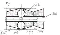
图12是图11所示的治疗构件的放大横截面视图,示出构成轴承配置的内部管状构件的方面。12 is an enlarged cross-sectional view of the treatment member shown in FIG. 11 showing aspects of the inner tubular member making up the bearing arrangement.

图13是构成图12所示的轴承配置的内部管状构件的变型的横截面视图。13 is a cross-sectional view of a variation of the inner tubular member making up the bearing arrangement shown in FIG. 12 .

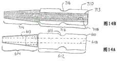
图14A和14B是构成轴承配置的内部管状构件的替代实施方式的侧视图。14A and 14B are side views of alternative embodiments of the inner tubular member making up the bearing arrangement.

图15是构成轴承配置的内部管状构件的另一实施方式的透视图。Figure 15 is a perspective view of another embodiment of the inner tubular member making up the bearing arrangement.

图16是构成轴承配置的内部管状构件的另一实施方式的透视图。Figure 16 is a perspective view of another embodiment of the inner tubular member making up the bearing arrangement.

图17A和17B分别是示出剪切边缘或剪切部分的治疗构件和外部管状构件的透视图。17A and 17B are perspective views, respectively, of a treatment member and an outer tubular member showing a sheared edge or portion.

图18A-18D是构成轴承配置的内部管状构件的实施方式的透视图。18A-18D are perspective views of an embodiment of an inner tubular member making up a bearing arrangement.

图19是具有轴承配置的治疗构件的另一实施方式的横截面视图。Figure 19 is a cross-sectional view of another embodiment of a treatment member having a bearing arrangement.

图20是根据进一步实施方式的医疗装置的横截面视图。Figure 20 is a cross-sectional view of a medical device according to a further embodiment.

图21是根据进一步实施方式的医疗装置的横截面视图。Figure 21 is a cross-sectional view of a medical device according to a further embodiment.

具体实施方式Detailed ways

参考附图,下面给出代表本文公开的医疗装置和方法的实例的用于从活体的身体内腔移除物质的医疗装置和方法的实施方式的详细描述。With reference to the accompanying drawings, a detailed description of embodiments of medical devices and methods for removing material from a body lumen of a living subject that represent examples of the medical devices and methods disclosed herein follows.

图1示意示出代表本文公开的创新医疗装置的实例的医疗装置的一种实施方式。此公开的医疗装置被构造成研磨身体内腔内的物质,诸如血管内的动脉硬化。本文使用的术语“研磨”和“研磨掉”不局限于作用在物质上的任何特定的操作或方法,并包括诸如研磨、刮削、磨损、烧蚀、浸渍或以其他方式将所需物质或材料分解成颗粒或其他较小的材料单元以便于从活体(如血管)中移除的操作。Figure 1 schematically illustrates one embodiment of a medical device that represents an example of the innovative medical device disclosed herein. The disclosed medical device is configured to abrade material within a bodily lumen, such as arteriosclerosis within a blood vessel. The terms "grinding" and "grinding away" as used herein are not limited to any particular operation or method of acting on a substance, and include methods such as grinding, scraping, abrasion, ablating, impregnating, or otherwise removing the desired substance or material The act of breaking down into particles or other smaller units of material to facilitate removal from a living body, such as a blood vessel.

图1所示的医疗装置100可以用来从血管BV研磨诸如图2A、2B所示的狭窄S,其中狭窄可以通过血栓、钙化病变等构成。开始参考图1,医疗装置100可包括治疗构件102和被构造成将转动驱动力传递到治疗构件102以转动治疗构件102的操作单元104。操作单元102可容纳在手柄108内。The medical device 100 shown in FIG. 1 may be used to grind a stenosis S such as that shown in FIGS. 2A, 2B from a blood vessel BV, where the stenosis may be formed by a thrombus, calcified lesion, or the like. Referring initially to FIG. 1 , the medical device 100 may include atreatment member 102 and anoperation unit 104 configured to transmit a rotational driving force to thetreatment member 102 to rotate thetreatment member 102 . Theoperating unit 102 can be housed within thehandle 108 .

操作单元104包括产生转动输出力的马达128。操作单元104还包括用于将马达128的转动输出轴传递或施加到驱动轴114的驱动机构区段122。驱动机构区段122包括驱动齿轮124和从动齿轮120,其彼此啮合使得驱动齿轮124的转动造成从动齿轮120的转动。马达128用作驱动源,并包括可转动马达轴130,驱动齿轮124固定到马达轴130,使得马达轴130和驱动齿轮124一起作为一个单元转动。马达128的操作造成马达轴130转动,继而造成驱动齿轮124转动。驱动轴114的近侧端部可固定到从动齿轮120,使得驱动轴114和从动齿轮120一起作为一个单元转动。因此,马达128的操作和马达轴130的转动通过驱动齿轮124、从动齿轮120和驱动轴114传递到齿轮构件102。包括电池126的电源区段106可设置在手柄108内,并连接到马达128以便为马达128供电。电缆110可连接到电池126以便供电。图1还示出医疗装置100可设置疏通管112以移除(即抽走或吸走)由物质S的研磨造成的碎片。Theoperation unit 104 includes amotor 128 that generates a rotational output force. Theoperating unit 104 also includes adrive mechanism section 122 for transmitting or applying a rotational output shaft of amotor 128 to thedrive shaft 114 . Thedrive mechanism section 122 includes adrive gear 124 and a drivengear 120 that mesh with each other such that rotation of thedrive gear 124 causes rotation of the drivengear 120 . Themotor 128 serves as a drive source, and includes arotatable motor shaft 130 to which thedrive gear 124 is fixed so that themotor shaft 130 and thedrive gear 124 rotate together as a unit. Operation of themotor 128 causes themotor shaft 130 to rotate, which in turn causes thedrive gear 124 to rotate. The proximal end ofdrive shaft 114 may be fixed to drivengear 120 such that driveshaft 114 and drivengear 120 rotate together as a unit. Accordingly, the operation of themotor 128 and the rotation of themotor shaft 130 are transmitted to thegear member 102 through thedrive gear 124 , the drivengear 120 and thedrive shaft 114 . Apower supply section 106 including abattery 126 may be disposed within thehandle 108 and connected to themotor 128 for powering themotor 128 .Cable 110 may be connected tobattery 126 for power. FIG. 1 also shows that the medical device 100 may be provided with a dredgetube 112 to remove (ie, aspirate or aspirate) debris caused by the grinding of the substance S. As shown in FIG.

驱动轴114可包括中空的管状驱动轴,使得中央内腔贯穿驱动轴114的整个轴向范围延伸。驱动轴114可优选为柔性的,但是也适用于将马达单元的转动输出从驱动轴114的近侧端部传递到驱动轴114的定位有治疗构件102的远侧端部。驱动轴114可以是任何期望构造。例如,驱动轴114可以通过单层或多层结构构成。例如,驱动轴114可以被构造成单层或多层螺旋钢丝或管,由例如SUS、作为金属的镍钛、或如聚乙烯或聚丙烯的聚烯烃、聚酰胺、如聚对苯二甲酸乙二醇酯的聚酯、如聚四氟乙烯聚合物的氟系列、聚醚醚酮,聚酰亚胺或其组合。管状驱动轴也可设置加强件。驱动轴的尺寸可以适当选择。适当尺寸的实例包括的0.40mm-1.40mm内直径和0.6mm–1.6mm的外直径。Driveshaft 114 may comprise a hollow tubular drive shaft such that a central lumen extends throughout the entire axial extent ofdrive shaft 114 . Thedrive shaft 114 may preferably be flexible, but is also suitable for transferring the rotational output of the motor unit from the proximal end of thedrive shaft 114 to the distal end of thedrive shaft 114 where thetreatment member 102 is positioned. Driveshaft 114 may be of any desired configuration. For example, thedrive shaft 114 may be constructed of a single layer or a multi-layer structure. For example, thedrive shaft 114 may be constructed as a single-layer or multi-layer helical steel wire or tube made of, for example, SUS, nickel titanium as metal, or polyolefin such as polyethylene or polypropylene, polyamide, polyethylene terephthalate, etc. Polyesters of glycol esters, fluorine series of polymers such as polytetrafluoroethylene, polyether ether ketone, polyimide or combinations thereof. The tubular drive shaft may also be provided with reinforcements. The size of the drive shaft can be appropriately selected. Examples of suitable dimensions include an inner diameter of 0.40mm-1.40mm and an outer diameter of 0.6mm–1.6mm.

驱动轴114优选为以上描述的管状驱动轴,使得驱动轴包括限定导丝接收通道的内腔。导丝通过驱动轴内的内腔并允许驱动轴114与治疗构件102一起行进穿过活体(例如血管的内腔),以便将治疗构件102定位在邻近待研磨物质的期望位置处。Driveshaft 114 is preferably a tubular drive shaft as described above such that the drive shaft includes a lumen defining a guidewire receiving channel. The guidewire passes through a lumen within the drive shaft and allows thedrive shaft 114 to be advanced with thetreatment member 102 through a living body (eg, the lumen of a blood vessel) in order to position thetreatment member 102 at a desired location adjacent to the material to be abraded.

驱动轴114可容纳在管状外部护套116内。外部护套116可以容纳驱动轴114的管状主体,使得驱动轴114能够相对于外部护套116并在外部护套116内转动和轴向运动。形成外部护套116的材料不局限于特定材料。通过实例,外部护套116可以由SUS、作为金属的NiTi或聚乙烯、聚丙烯、聚烯烃(如聚对苯二甲酸乙二醇酯)、聚酯(如聚对苯二甲酸乙二醇酯)、氟基聚合物(如聚四氟乙烯、聚醚醚酮、聚酰亚胺等)或此类材料的组合。Thedrive shaft 114 may be housed within a tubularouter sheath 116 .Outer sheath 116 may house the tubular body ofdrive shaft 114 such that driveshaft 114 is capable of rotational and axial movement relative to and withinouter sheath 116 . The material forming theouter sheath 116 is not limited to a specific material. By way of example, theouter sheath 116 may be made of SUS, NiTi as metal or polyethylene, polypropylene, polyolefin such as polyethylene terephthalate, polyester such as polyethylene terephthalate ), fluorine-based polymers (such as polytetrafluoroethylene, polyether ether ketone, polyimide, etc.), or a combination of such materials.

马达128的操作可以通过开关132控制。操作或接通开关132造成马达128操作并转动马达轴130。因此,驱动齿轮124转动并继而转动与驱动齿轮124啮合的从动齿轮120。从动齿轮120的转动造成驱动轴114转动,最终造成齿轮构件102转动。医疗装置100还包括转动机构113,图1示意示出,其操作地连接到外部护套116,以便如图1箭头总体所示地转动外部护套。Operation ofmotor 128 may be controlled byswitch 132 . Operating or turning onswitch 132 causes motor 128 to operate and rotatemotor shaft 130 . Accordingly, thedriving gear 124 rotates and in turn rotates the drivengear 120 meshing with thedriving gear 124 . Rotation of the drivengear 120 causes thedrive shaft 114 to rotate, which ultimately causes thegear member 102 to rotate. The medical device 100 also includes arotation mechanism 113 , shown schematically in FIG. 1 , which is operatively connected to anouter sheath 116 for rotating the outer sheath as generally indicated by the arrows in FIG. 1 .

图2A和2B示出可以设置在管状外部护套116和驱动轴114内的弯曲区段118。此弯曲区段118可以沿着驱动轴114和外部护套116的长度设置在中间点处。在此弯曲区段118内,外部护套116和驱动轴14如图2A、2B所示弯曲。这允许治疗单元102以允许血管BV内定位的狭窄S的研磨的方式操纵。即,随着驱动轴114通过马达128的操作而转动并随着外部护套116通过转动机构113的操作而转动,治疗构件102遵循圆形或环形的运动路径,同时治疗构件102围绕其中心轴线转动。图2A和2B还示出在医疗装置操纵期间在治疗构件102定位在活体(血管)内且进行转动的同时,治疗构件102的远侧端部向远侧超过外部活体116的最远侧端部定位。2A and 2B illustrate acurved section 118 that may be disposed within tubularouter sheath 116 and driveshaft 114 . Thiscurved section 118 may be provided at an intermediate point along the length of thedrive shaft 114 andouter sheath 116 . Within thisbend section 118, theouter sheath 116 and drive shaft 14 bend as shown in Figures 2A, 2B. This allows thetreatment unit 102 to be manipulated in a manner that allows grinding of a localized stenosis S within the blood vessel BV. That is, as thedrive shaft 114 is rotated by operation of themotor 128 and as theouter sheath 116 is rotated by operation of therotation mechanism 113, thetreatment member 102 follows a circular or circular path of motion while thetreatment member 102 orbits its central axis turn. 2A and 2B also illustrate that the distal end of thetreatment member 102 passes distally beyond the most distal end of theouter living body 116 while thetreatment member 102 is positioned within the living body (vessel) and rotated during manipulation of the medical device. position.

图3和4示出与连接到驱动轴114的远侧端部的治疗构件102相关的附加细节。图3和4示出可以中心地设置在驱动轴114内以便如上所述地接收导丝的中心定位导丝内腔115。如上所述,在医疗装置操作期间,治疗构件102的远侧端部向远侧超过外部护套116的最远侧端部定位。图3和4示出向远侧延伸超过管状外部护套116的最远侧端部并因此暴露的治疗构件102(即治疗构件102未被外部护套116覆盖)。在操作期间向远侧超过外部护套116的远侧端部暴露的治疗构件102可包括最远侧端部136、中间部分138和近侧端部140。中间部分138轴向定位在最远侧端部136和近侧端部140之间。最远侧端部136、中间部分138和近侧端部140可以优选构造成有助于身体内腔内的物质(例如血管BV内的狭窄S)的研磨。实现这种结果的一种方式在于使治疗构件102的最远侧端部136、中间部分138和近侧端部140设置涂层,以有助于身体内腔内的物质的研磨。涂层的实例是金刚石研磨涂层。金刚石研磨涂层指的是金刚砂的涂层,涉及相对小粒的金刚石(例如~30um直径)和金属电镀(Ni,Co,Cr等)。这种类型涂层的实例是在由PFERD产生的电镀金刚石工具中使用的涂层。3 and 4 show additional details related to thetreatment member 102 coupled to the distal end of thedrive shaft 114 . 3 and 4 illustrate a centrally locatedguidewire lumen 115 that may be centrally disposed within thedrive shaft 114 to receive a guidewire as described above. As noted above, during operation of the medical device, the distal end of thetreatment member 102 is positioned distally beyond the distal-most end of theouter sheath 116 . 3 and 4 show thetreatment member 102 extending distally beyond the distal-most end of the tubularouter sheath 116 and thus exposed (ie, thetreatment member 102 is not covered by the outer sheath 116). Thetreatment member 102 exposed distally beyond the distal end of theouter sheath 116 during operation may include adistal-most end 136 , anintermediate portion 138 , and aproximal end 140 .Intermediate portion 138 is positioned axially betweendistal-most end 136 andproximal end 140 . Thedistal-most end 136,intermediate portion 138, andproximal end 140 may preferably be configured to facilitate abrading of material within a body lumen, such as a stenosis S within a blood vessel BV. One way to achieve this result is by coating thedistal-most end 136,intermediate portion 138, andproximal end 140 of thetreatment member 102 to facilitate abrading of material within the body lumen. An example of a coating is a diamond abrasive coating. Diamond abrasive coating refers to the coating of diamond, involving relatively small grains of diamond (eg ~30um diameter) and metal plating (Ni, Co, Cr, etc.). An example of this type of coating is the coating used in electroplated diamond tools produced by PFERD.

治疗构件102的最远侧端部136包括远侧渐缩部分142和近侧渐缩部分144。近侧渐缩部分144定位在远侧渐缩部分142的近侧。远侧渐缩部分142以变窄方式朝着治疗构件102的最远侧端部一致性渐缩,而近侧渐缩部分144以变窄方式朝着治疗构件102的最近侧端部一致性渐缩。治疗构件102的最远侧端部136还可包括定位在远侧渐缩部分142和近侧渐缩部分144之间的恒定外直径中间部分143。在所示实施方式中,有助于身体内腔内的物质研磨的涂层没有设置在恒定外直径中间部分143上。当然,施加到治疗构件102的剩余部分的外表面上的涂层也可设置在恒定外直径中间部分143的外表面上。中间部分143可以是用于有助于转动的前部球轴承的覆盖环的形式。Thedistal-most end 136 of thetreatment member 102 includes adistal taper 142 and aproximal taper 144 . Proximaltapered portion 144 is positioned proximally of distal taperedportion 142 . Distaltapered portion 142 consistently tapers in a narrowing manner toward the distal-most end oftreatment member 102, while proximaltapered portion 144 consistently tapers in a narrowing manner toward the proximal-most end oftreatment member 102. shrink. Thedistal-most end 136 of thetreatment member 102 may also include a constant outer diameterintermediate portion 143 positioned between a distal taperedportion 142 and a proximaltapered portion 144 . In the illustrated embodiment, a coating that facilitates abrading of material within the body lumen is not provided on the constant outer diameterintermediate portion 143 . Of course, the coating applied to the outer surface of the remainder of thetreatment member 102 may also be provided on the outer surface of the constant outer diameterintermediate portion 143 . Themiddle portion 143 may be in the form of a cover ring for a front ball bearing to facilitate rotation.

中间部分138可以是图3和4所示的渐缩部分,其中中间部分沿着从中间部分138的最近侧端部到中间部分138的最远侧端部的整个范围以恒定方式渐缩。中间部分138朝着治疗构件102的最远侧端部渐缩,使得中间部分138的外直径在远侧方向上逐渐变窄。Theintermediate portion 138 may be a tapered portion as shown in FIGS. 3 and 4 , wherein the intermediate portion tapers in a constant manner along the entire extent from the most proximal end of theintermediate portion 138 to the most distal end of theintermediate portion 138 .Intermediate portion 138 tapers toward the distal-most end oftreatment member 102 such that the outer diameter ofintermediate portion 138 tapers in the distal direction.

近侧端部140可如图3和4所示沿着其整个轴向范围具有恒定外直径。Theproximal end 140 may have a constant outer diameter along its entire axial extent as shown in FIGS. 3 and 4 .

治疗构件102也设置与治疗构件102内的中空内部或内腔连通的至少一个窗口或通孔150。治疗构件102可包括多个周向间隔开的窗口或通孔150。例如,如图7A和7B所示,治疗构件102可设置以相同角度间隔周向间隔开的三个窗口或通孔150。当然,可以设置不同数量的窗口或通孔,并且它们可以布置在不同于图7A和7B所示的相对位置处。Thetreatment member 102 is also provided with at least one window or throughhole 150 in communication with the hollow interior or lumen within thetreatment member 102 . Thetreatment member 102 may include a plurality of circumferentially spaced windows or throughholes 150 . For example, as shown in Figures 7A and 7B, thetreatment member 102 may be provided with three windows or through-holes 150 circumferentially spaced at equal angular intervals. Of course, a different number of windows or through holes could be provided, and they could be arranged in relative positions other than those shown in Figures 7A and 7B.

如上所述,每个窗口或通孔150通向治疗构件102内的中空内部或内腔(出入内腔)。治疗构件102的内腔或中空内部如图4所示与外部护套116内的内腔117连通。图1所示的疏通管112与外部护套116内的内腔117连接或流体连通。疏通管112连接到图1示意所示的疏通源或抽吸装置111。As noted above, each window or throughhole 150 opens into a hollow interior or lumen within the treatment member 102 (in and out of the lumen). The lumen or hollow interior oftreatment member 102 communicates withlumen 117 withinouter sheath 116 as shown in FIG. 4 . Unclogtube 112 shown in FIG. 1 is connected or in fluid communication withlumen 117 withinouter sheath 116 . The unclogtube 112 is connected to an unclog source or suction device 111 shown schematically in FIG. 1 .

在医疗装置100操作期间,治疗构件102通过马达128的操作转动以便研磨身体内腔BV内的物质S(例如血管内的狭窄)。在治疗构件102研磨身体内腔内的物质时,抽吸源111操作以便将由研磨操作产生的碎片抽吸经过治疗构件102内的窗口或通孔150,进入治疗构件102内的内腔或中空内部,并进入外部护套116内的内腔117。碎片接着通过抽吸装置111从身体内腔抽出或移除。During operation of the medical device 100, thetreatment member 102 is rotated by operation of themotor 128 so as to abrade a substance S (eg, a stenosis within a blood vessel) within the body lumen BV. Astreatment member 102 abrades material within a bodily lumen, suction source 111 operates to draw debris generated by the abrading operation through window or throughhole 150 intreatment member 102 and into the lumen or hollow interior withintreatment member 102 , and enter thelumen 117 within theouter sheath 116. The debris is then aspirated or removed from the body lumen by the suction device 111 .

如图4所示,治疗构件102的近侧端部包括限定治疗构件102的轴部分152的缩小外直径部分。治疗构件102的此缩小外直径轴部分152代表用于接收代表轴轴承或套筒构件的外部管状构件160的座置区域。内腔贯穿外部管状构件160的整个轴向范围延伸(即穿过外部管状构件160),并且治疗构件的缩小外直径轴部分152定位在贯穿外部管状构件160的整个轴向范围延伸的内腔内。管状构件160能够相对于治疗构件102转动。即,如上所述,治疗构件102通过驱动轴114转动驱动,并且治疗构件102相对于管状构件160转动。As shown in FIG. 4 , the proximal end of thetreatment member 102 includes a reduced outer diameter portion that defines ashaft portion 152 of thetreatment member 102 . This reduced outerdiameter shaft portion 152 of thetreatment member 102 represents a seating area for receiving an outertubular member 160 representing a shaft bearing or sleeve member. The lumen extends throughout the entire axial extent of the outer tubular member 160 (i.e., passes through the outer tubular member 160), and the reduced outerdiameter shaft portion 152 of the treatment member is positioned within the lumen extending through the entire axial extent of the outertubular member 160 .Tubular member 160 is rotatable relative totreatment member 102 . That is, as described above, thetreatment member 102 is rotationally driven by thedrive shaft 114 and thetreatment member 102 rotates relative to thetubular member 160 .

轴向延伸内腔贯穿缩小外直径轴部分152的整个长度延伸(即,穿过缩小外直径轴部分152)。缩小外直径轴部分152的此内腔与驱动轴114内的内腔115连通并同轴。缩小外直径轴部分152内的内腔也与图3所示的治疗构件102的最远侧端部处的开口端部119同轴,并通向治疗构件102的内腔并与其连通。The axially extending lumen extends throughout the entire length of the reduced outer diameter shaft portion 152 (ie, through the reduced outer diameter shaft portion 152). This lumen of reduced outerdiameter shaft portion 152 communicates with and is coaxial withlumen 115 indrive shaft 114 . The lumen within reduced outerdiameter shaft portion 152 is also coaxial withopen end 119 at the distal-most end oftreatment member 102 shown in FIG. 3 and opens into and communicates with the lumen oftreatment member 102 .

轴承可定位在缩小外直径轴部分152的外表面和外部管状构件160的内表面之间,以有助于缩小外直径轴部分152和外部管状构件160之间的相对转动。外部管状构件160可因此安装在治疗构件102上,其中轴承位于外部管状构件160和治疗构件102之间。轴承可以具有任何期望构型,包括多个滚子轴承162,如图4所示。滚子轴承162有助于治疗构件102和外部管状构件160之间的相对转动。Bearings may be positioned between the outer surface of reduced outerdiameter shaft portion 152 and the inner surface of outertubular member 160 to facilitate relative rotation between reduced outerdiameter shaft portion 152 and outertubular member 160 . The outertubular member 160 may thus be mounted on thetreatment member 102 with the bearings positioned between the outertubular member 160 and thetreatment member 102 . The bearings may have any desired configuration, including a plurality ofroller bearings 162, as shown in FIG. 4 .Roller bearings 162 facilitate relative rotation betweentreatment member 102 and outertubular member 160 .

如图4所示,管状构件160的外周表面可以凹入,以限定径向向内凹入部分,径向向内凹入部分限定凹部164。凹部164具有有限的周向范围(即,凹部164不围绕外部管状构件160的整个周向范围延伸),使得凹部164具有小于360度、优选小于180度的周向范围。凹部164从外部管状构件160的最近侧端部朝着外部管状构件160的远侧端部延伸。凹部164因此通向外部管状构件160的最近侧端部,并且延伸小于外部管状构件160的整个周向范围延伸,使得凹部164的最远侧端部通过壁166限定。图4示出外部管状构件160的外表面内的凹部164接收外部护套116的远侧端部处的向远侧延伸突出部。外部护套116的向远侧延伸突出部168和外部管状构件160内的凹部166之间的接合转动地固定外部护套116和外部管状构件160,使得外部护套116和外部管状构件160不相对于彼此转动。因此,在治疗构件102通过马达128的操作转动时,治疗构件102相对于外部护套116和外部管状构件160两者转动。As shown in FIG. 4 , the outer peripheral surface of thetubular member 160 may be concave to define a radially inwardly recessed portion defining arecess 164 .Recess 164 has a limited circumferential extent (ie,recess 164 does not extend around the entire circumferential extent of outer tubular member 160 ), such thatrecess 164 has a circumferential extent of less than 360 degrees, preferably less than 180 degrees.Recess 164 extends from the proximal-most end of outertubular member 160 toward the distal end of outertubular member 160 . Recess 164 thus opens into the proximal-most end of outertubular member 160 and extends less than the entire circumferential extent of outertubular member 160 such that the distal-most end ofrecess 164 is defined bywall 166 . FIG. 4 shows that therecess 164 in the outer surface of the outertubular member 160 receives the distally extending protrusion at the distal end of theouter sheath 116 . Engagement between distally extending protrusion 168 ofouter sheath 116 andrecess 166 in outertubular member 160 rotationally securesouter sheath 116 and outertubular member 160 such thatouter sheath 116 and outertubular member 160 are not opposed rotate with each other. Thus, astreatment member 102 is rotated by operation ofmotor 128 ,treatment member 102 rotates relative to bothouter sheath 116 and outertubular member 160 .

外部管状构件160也可包括至少一个径向向内指向突出部170。在图6所示的外部管状构件160的所示实施方式中,外部管状构件160包括两个突出部170,每个突出部径向向内朝着轴向贯穿外部管状构件160的内腔指向。两个突出部170可定位成彼此径向相对。每个突出部170具有有限的周向范围,指的是每个突出部170具有小于360度的周向范围,如外部管状构件160的轴向端部观看那样。每个突出部170可具有小于180度、更优选地小于90度的周向范围。每个突出部170具有有限的周向范围,使得突出部170具有两个周向间隔开的侧表面,该侧表面分别从外部管状构件160的外周表面朝着外部管状构件160的内腔延伸。突出部170可以形成在外部管状构件160的远侧端部的部分内。Outertubular member 160 may also include at least one radially inwardly directedprotrusion 170 . In the illustrated embodiment of the outertubular member 160 shown in FIG. 6 , the outertubular member 160 includes twoprotrusions 170 each directed radially inward toward a lumen axially extending through the outertubular member 160 . The twoprotrusions 170 may be positioned diametrically opposite to each other. Eachprotrusion 170 has a limited circumferential extent, meaning eachprotrusion 170 has a circumferential extent of less than 360 degrees, as viewed from the axial end of the outertubular member 160 . Eachprotrusion 170 may have a circumferential extent of less than 180 degrees, more preferably less than 90 degrees. Eachprotrusion 170 has a limited circumferential extent such that theprotrusion 170 has two circumferentially spaced side surfaces extending from the outer peripheral surface of the outertubular member 160 towards the lumen of the outertubular member 160 , respectively.Protrusion 170 may be formed in a portion of the distal end of outertubular member 160 .

外部管状构件160还可包括定位在每个突出部170的一个周向侧部内上的凹部172。即,如图6所示,凹部172在顺时针方向上定位在每个突出部170的前部内。凹部172因此在一个周向侧部上通过突出部170的侧表面限界。每个凹部172可以是轴向指向的凹部,指的是每个凹部172在轴向上从外部管状构件160的最远侧轴向端部表面(图6左侧处的轴向端部表面)朝着外部管状构件160的最近侧轴向端部(图6右侧处的轴向端部)凹入。这因此沿着每个突出部170的一侧形成沟槽或轴向凹入区域。这些沟槽174中的每个被构造成接收由研磨身体内腔BV内的物质S(血管内的动脉硬化)造成的碎片D。接收在沟槽174内的这种碎片的实例总体在图8内示出。The outertubular member 160 may also include arecess 172 positioned on one circumferential side of eachprotrusion 170 . That is, as shown in FIG. 6 , therecess 172 is positioned in the front of eachprotrusion 170 in the clockwise direction. Therecess 172 is thus delimited on one circumferential side by the side surface of theprotrusion 170 . Eachrecess 172 may be an axially directed recess, meaning that eachrecess 172 extends axially from the most distal axial end surface of the outer tubular member 160 (the axial end surface at the left in FIG. 6 ). It is recessed toward the proximal-most axial end of the outer tubular member 160 (the axial end on the right in FIG. 6 ). This thus forms a groove or axially recessed area along one side of eachprotrusion 170 . Each of thesegrooves 174 is configured to receive debris D caused by grinding the substance S within the body lumen BV (arteriosclerosis within the vessel). An example of such debris received within thegroove 174 is shown generally in FIG. 8 .

每个突出部170被构造成限定两个剪切部分,每个剪切部分与治疗构件102上的相应剪切部分相互作用,以便将剪切力施加到碎片D。施加到碎片D上的这种剪切力将破坏碎片或减小碎片的尺寸。如图6所示,例如,外部管状构件160上的剪切部分的第一个包括位于突出部170的边缘上的剪切边缘176。通过突出部170的边缘限定的这种第一剪切部分176是外部管状构件160的径向延伸剪切边缘,指的是它在从外部管状构件160的外表面到外部管状构件160的内表面的方向上延伸。Eachprotrusion 170 is configured to define two shearing portions, each shearing portion interacting with a corresponding shearing portion on thetreatment member 102 to apply a shearing force to the fragments D . This shear force applied to the fragments D will break the fragments or reduce the size of the fragments. As shown in FIG. 6 , for example, a first one of the sheared portions on the outertubular member 160 includes a shearededge 176 located on an edge of theprotrusion 170 . This first shearedportion 176 defined by the edge of theprotrusion 170 is the radially extending sheared edge of the outertubular member 160, meaning that it extends from the outer surface of the outertubular member 160 to the inner surface of the outertubular member 160. extended in the direction.

外部管状构件160上的第二剪切部分通过突出部170的内周边上的剪切边缘178限定。通过突出部170的内周边上的边缘限定的这种第二剪切部分178是外部管状构件160的轴向延伸剪切边缘,指的是它在平行于外部管状构件160的中心轴线的轴向上延伸。图17B示出外部管状构件160上的第一剪切部分176和外部管状构件160上的第二剪切部分178。The second sheared portion on the outertubular member 160 is defined by a sheared edge 178 on the inner periphery of theprotrusion 170 . This second sheared portion 178 defined by the edge on the inner periphery of theprotrusion 170 is the axially extending sheared edge of the outertubular member 160 , referring to its axial direction parallel to the central axis of the outertubular member 160 . Extend up. FIG. 17B shows afirst cutout 176 on the outertubular member 160 and a second cutout 178 on the outertubular member 160 .

管状构件160上的第一剪切部分(剪切边缘)与治疗构件102上的第一剪切部分或剪切边缘180相互作用。治疗构件102上的第一剪切部分180通过邻近窗口150的缩小外直径部分152的远侧端部处的径向延伸边缘限定。管状构件160上的第一剪切部分或剪切边缘176和治疗构件102上的第一剪切部分或剪切边缘180在治疗构件102和外部管状构件160之间相对转动期间彼此径向重叠,指的是它们具有类似的径向范围。在治疗构件102相对于管状构件160转动期间,定位在管状构件160的沟槽174内的碎片D受到管状构件160上的第一剪切部分或剪切边缘176和治疗构件102上的第一剪切部分或剪切边缘180之间的剪切作用。A first sheared portion (sheared edge) ontubular member 160 interacts with a first sheared portion or shearededge 180 ontreatment member 102 . Afirst cutout portion 180 on thetreatment member 102 is defined by a radially extending edge at the distal end of the reducedouter diameter portion 152 adjacent thewindow 150 . The first sheared portion or edge 176 on thetubular member 160 and the first sheared portion or edge 180 on thetreatment member 102 radially overlap each other during relative rotation between thetreatment member 102 and the outertubular member 160, It means that they have similar radial extent. During rotation of thetreatment member 102 relative to thetubular member 160, the debris D positioned within thegroove 174 of thetubular member 160 is subjected to a first shear portion orshear edge 176 on thetubular member 160 and a first shear on thetreatment member 102. The shearing action between the cut portions or shearededges 180.

管状构件160上的第二剪切部分(剪切边缘)178与治疗构件102上的第二剪切部分或剪切边缘182相互作用。治疗构件102上的第二剪切部分182通过邻近窗口150的缩小外直径部分152处的轴向延伸边缘限定。管状构件160上的第二剪切部分或剪切边缘178和治疗构件102上的第二剪切部分或剪切边缘182在治疗构件102和外部管状构件160之间相对转动期间彼此轴向重叠,指的是它们具有类似的轴向范围。在治疗构件102相对于外部管状构件160转动期间,外部管状构件160的沟槽174内的碎片D将受到管状构件160上的第二剪切部分178和治疗构件102上的第二剪切部分182之间的剪切作用。图17A示出治疗构件102上的第一剪切部分180和治疗构件102上的第二剪切部分182。A second sheared portion (sheared edge) 178 ontubular member 160 interacts with a second sheared portion or shearededge 182 ontreatment member 102 . Asecond cutout portion 182 on thetreatment member 102 is defined by an axially extending edge adjacent the reducedouter diameter portion 152 of thewindow 150 . The second sheared portion or edge 178 on thetubular member 160 and the second sheared portion or edge 182 on thetreatment member 102 axially overlap each other during relative rotation between thetreatment member 102 and the outertubular member 160, It means that they have similar axial extent. During rotation of thetreatment member 102 relative to the outertubular member 160, the debris D within thegroove 174 of the outertubular member 160 will be subjected to the second shear portion 178 on thetubular member 160 and thesecond shear portion 182 on thetreatment member 102. the shearing effect between them. FIG. 17A shows afirst cutout 180 on thetreatment member 102 and asecond cutout 182 on thetreatment member 102 .

因此,在身体内腔BV内的物质S研磨期间,随着定位在身体内腔内的治疗构件102相对于外部管状构件160转动,外部管状构件160的沟槽174内的碎片D将受到管状构件160上的第一剪切部分或剪切部分176和治疗构件102上的第一剪切部分或剪切边缘180之间的剪切力和管状构件160上的第二剪切部分或剪切边缘178和治疗构件102上的第二剪切部分或剪切边缘182之间的剪切力中的一者或两者。这种剪切力将破坏或减小碎片D的尺寸。因此,进入内腔184(如图3轴向指向虚线箭头示意所示)的碎片的尺寸将减小尺寸,并且将不太容易造成内腔184堵塞。治疗构件的转动速度范围可以从5000rpm到200000rpm、更优选从10000rpm到120000rpm。外部护套的转动速度可以是5rpm到5000rpm。治疗构件的转动方向可以与外部护套的转动方向相同。治疗构件的转动方向可以与外部护套的转动方向相反。治疗构件的转动方向可以与外部的转动方向相反。如上所述,外部护套的转动可以通过图1示意所示的转动机构113进行。Thus, during grinding of the substance S within the body lumen BV, as thetreatment member 102 positioned within the body lumen is rotated relative to the outertubular member 160, the debris D within thegroove 174 of the outertubular member 160 will be subjected to damage by the tubular member. The shear force between the first shear portion orshear portion 176 on 160 and the first shear portion or edge 180 on thetreatment member 102 and the second shear portion or edge 180 on thetubular member 160 178 and a second shearing portion orshearing edge 182 on thetreatment member 102 or both. This shear force will destroy or reduce the size of the fragment D. Thus, debris entering lumen 184 (as schematically indicated by the axially pointing dashed arrows in FIG. 3 ) will be reduced in size and will be less likely to cause clogging oflumen 184 . The rotational speed of the treatment member may range from 5000 rpm to 200000 rpm, more preferably from 10000 rpm to 120000 rpm. The rotational speed of the outer sheath may be from 5 rpm to 5000 rpm. The direction of rotation of the treatment member may be the same as the direction of rotation of the outer sheath. The direction of rotation of the treatment member may be opposite to the direction of rotation of the outer sheath. The direction of rotation of the treatment member may be opposite to the direction of rotation of the outer portion. As mentioned above, the rotation of the outer sheath can be performed by therotation mechanism 113 shown schematically in FIG. 1 .

如图8所示,外部管状构件160的第一剪切部分或剪切边缘176通常通过在弯曲区段(边缘部分)190处交叉或相遇的两个线性或直线分段(边缘部分)188来限定,使得第一剪切部分176阻止图8所示的构型或形状。在治疗构件102相对于外部管状构件160转动期间,力如图8箭头总体所示施加到碎片D。此箭头示出外直径处的力大于内直径处的力,使得由研磨物质造成的碎片被迫进入径向内侧。从疏通碎片的观点来说,这会是有利的。As shown in FIG. 8 , the first sheared portion or edge 176 of the outertubular member 160 is generally separated by two linear or rectilinear segments (edge portions) 188 that intersect or meet at a curved section (edge portion) 190 . Defined such that thefirst shear portion 176 resists the configuration or shape shown in FIG. 8 . During rotation of thetreatment member 102 relative to the outertubular member 160, a force is applied to the fragment D as generally indicated by the arrows in FIG. 8 . This arrow shows that the force at the outer diameter is greater than the force at the inner diameter, so that debris from the abrasive substance is forced radially inward. From the point of view of unclogging debris, this can be beneficial.

在图8所示的剪切机构的实施方式中,突出部170的内表面或内周边的形状与治疗构件102的缩小外直径部分152的外周边或外表面的形状匹配或相同。因此,管状构件160上的第二剪切部分或剪切边缘178的形状与治疗构件102上的第二剪切部分或剪切边缘182的形状匹配或相同。In the embodiment of the shearing mechanism shown in FIG. 8 , the shape of the inner surface or perimeter ofprotrusion 170 matches or is identical to the shape of the outer perimeter or surface of reducedouter diameter portion 152 oftreatment member 102 . Thus, the shape of the second cutout portion or edge 178 on thetubular member 160 matches or is the same as the shape of the second cutout portion or edge 182 on thetreatment member 102 .

图9A示出管状区段160上的第一剪切部分或剪切边缘和管状构件160上的第二剪切部分或剪切边缘的变型形式。在此实施方式中,外部管状构件上的第一剪切部分或剪切边缘276是直线或线性剪切部分(线性剪切边缘)的形式,其在其整个范围上是直线或线性的。在治疗构件102相对于外部管状构件160转动期间,由身体内腔BV内的物质S(血管内的动脉硬化)研磨造成的碎片受到由箭头9A指示的力,以朝着由外部管状构件160的第二剪切部分或剪切边缘和治疗构件102的第二剪切部分182限定的剪切区域压迫。外部管状构件的第二剪切部分或剪切边缘是类似于图6所示的第二剪切部分或剪切边缘178的轴向延伸剪切边缘。在第一剪切部分或剪切边缘276的外部点与外部管状构件160的第一剪切部分或剪切边缘180交叉时,外部管状构件上的第一剪切部分或剪切边缘276相对于外部管状构件160的第一剪切部分或剪切边缘180形成角度

Figure BDA0002266067170000151
角度
Figure BDA0002266067170000152
可以大于0°。关系
Figure BDA0002266067170000153
可以有利于帮助向内推动碎片,结果是有助于疏通目的。FIG. 9A shows a variation of a first cutout or cutout edge ontubular section 160 and a second cutout or cutout edge ontubular member 160 . In this embodiment, the first sheared portion or edge 276 on the outer tubular member is in the form of a straight or linear sheared portion (linear sheared edge) that is straight or linear throughout its extent. During the rotation of thetreatment member 102 relative to the outertubular member 160, the debris caused by the grinding of the substance S (intravascular arteriosclerosis) in the body lumen BV is subjected to the force indicated by the arrow 9A to move towards the direction of the outertubular member 160 The second shear portion or edge and the shear region defined by thesecond shear portion 182 of thetreatment member 102 compress. The second sheared portion or edge of the outer tubular member is an axially extending sheared edge similar to second sheared portion or edge 178 shown in FIG. 6 . When the outer point of the first cut portion or cutedge 276 intersects the first cut portion or cutedge 180 of the outertubular member 160, the first cut portion or cutedge 276 on the outer tubular member is relatively A first sheared portion or shearededge 180 of the outertubular member 160 forms an angle
Figure BDA0002266067170000151
angle
Figure BDA0002266067170000152
Can be greater than 0°. relation
Figure BDA0002266067170000153
Can be beneficial to help push debris inwards and the result is helpful for unclog purposes.

图9A所示的向内指向突出部的构型也可略微不同于图8所示的向内指向突出部170的构型。在图9A所示的实施方式中,外部管状构件160的向内指向突出部的部分279的形状与治疗构件102的缩小外直径部分的外周边的形状不匹配。The configuration of the inwardly directed protrusions shown in FIG. 9A may also differ slightly from the configuration of the inwardly directedprotrusions 170 shown in FIG. 8 . In the embodiment shown in FIG. 9A , the shape of the inwardly directedprotrusion portion 279 of the outertubular member 160 does not match the shape of the outer perimeter of the reduced outer diameter portion of thetreatment member 102 .

图9B示出外部管状构件上的剪切机构的构型的进一步实施方式。在图9B的实施方式中,剪切机构包括与图8所示相同且如上所述的第一剪切部分或剪切边缘376以及也与图8所示的第二剪切部分或剪切边缘178类似的第二剪切部分或剪切边缘。在图9B的实施方式中,外部管状构件的向内指向突出部的部分379的形状如图9A所示,其中部分379的形状与治疗构件102的缩小外直径部分的外周边的形状不匹配。剪切机构的这种构型形成大于0°的角度

Figure BDA0002266067170000154
和小于0°的角度
Figure BDA0002266067170000157
图9B示出的关系
Figure BDA0002266067170000156
Figure BDA0002266067170000155
可有利于在弯曲结构376(176)的中心处截留碎片,以便将强力施加到碎片,使其成为细小碎片。Figure 9B shows a further embodiment of the configuration of the shear mechanism on the outer tubular member. In the embodiment of FIG. 9B, the shearing mechanism includes a first shearing portion or edge 376 identical to that shown in FIG. 8 and described above and a second shearing portion or edge 376 also shown in FIG. 178 similar second cut portion or cut edge. In the embodiment of FIG. 9B , the inwardly directedprotrusion portion 379 of the outer tubular member is shaped as shown in FIG. 9A , wherein the shape ofportion 379 does not match the shape of the outer perimeter of the reduced outer diameter portion oftreatment member 102 . This configuration of the shear mechanism forms an angle greater than 0°
Figure BDA0002266067170000154
and angles less than 0°
Figure BDA0002266067170000157
Figure 9B shows the relationship
Figure BDA0002266067170000156
and
Figure BDA0002266067170000155
It may be advantageous to trap fragments at the center of the curved structure 376 (176) in order to apply a strong force to the fragments into fine fragments.

图10B-10I示出外部管状构件上的剪切部分或剪切边缘的构型的进一步实施方式。图10A的虚线示出图10B-10I的顶视图和透视图所采用的位置。图10B和10C所示的外部管状构件261的实施方式没有位于管状构件的外部轴向表面上的窗口或凹部(即图10A所示的窗口W,其类似于图6所示的轴向指向凹部172,在图10B和10C所示的实施方式中不存在),并包括第一剪切边缘261’和第二剪切边缘261”,其中第二剪切边缘261”平行于外部管状构件的中心轴线(如图10C中虚线所示)。在图10D和10E所示的管状构件262的实施方式中,管状构件的外部轴向表面上的窗口或轴向延伸凹部被构造成使得窗口的壁和外部轴向表面之间具有90°角度(Φ=90°),并包括第一剪切边缘262’和第二剪切边缘262”,其中第二剪切边缘262”平行于外部管状构件的中心轴线。如图10D所示,管状构件的外部轴向表面上的窗口或轴向延伸凹部W从顶部观看是矩形形状。在图10F和10G所示的外部管状构件263的实施方式中,管状构件的外部轴向表面上的窗口或轴向延伸凹部被构造成使得窗口的壁和外部轴向表面之间的角度Φ小于90°(Φ<90°),并且包括第一剪切边缘263’和第二剪切边缘263”,其中第二剪切边缘263”不平行于外部管状构件的中心轴线。如图10F所示,管状构件的外部轴向表面上的窗口或轴向延伸凹部W’从顶部观看时是梯形形状(截锥形状)。在图10H和10I所示的外部管状构件264的实施方式中,管状构件的外部轴向表面上的窗口或轴向延伸凹部被构造成使得窗口的壁和外部轴向表面之间的角度Φ小于90°(Φ<90°),并且突出部表面如所示卷绕,并且包括第一剪切边缘264’和第二剪切边缘264”,其中第二剪切边缘264”不平行于外部管状构件的中心轴线。如图10H所示,管状构件的外部轴向表面上的窗口或轴向延伸凹部W’从顶部观看时是梯形形状(截锥形状)。图10F-10I所示的实施方式被构造成使得第一剪切边缘用作刀片并非常适用于形成相对强的剪切力。10B-10I illustrate further embodiments of the configuration of the sheared portion or edge on the outer tubular member. The dashed lines in Figure 10A show the positions taken by the top and perspective views of Figures 10B-10I. The embodiment of the outertubular member 261 shown in FIGS. 10B and 10C does not have a window or recess on the outer axial surface of the tubular member (i.e., window W shown in FIG. 10A , which is similar to the axially directed recess shown in FIG. 6 ). 172, not present in the embodiment shown in Figures 10B and 10C), and includes a first shearing edge 261' and asecond shearing edge 261", wherein thesecond shearing edge 261" is parallel to the center of the outer tubular member Axis (as shown by the dotted line in Fig. 10C). In the embodiment of thetubular member 262 shown in FIGS. 10D and 10E , the window or axially extending recess on the outer axial surface of the tubular member is configured such that there is a 90° angle between the wall of the window and the outer axial surface ( Φ=90°), and includes a first shearing edge 262' and asecond shearing edge 262", wherein thesecond shearing edge 262" is parallel to the central axis of the outer tubular member. As shown in Figure 10D, the window or axially extending recess W on the outer axial surface of the tubular member is rectangular in shape when viewed from the top. In the embodiment of the outertubular member 263 shown in FIGS. 10F and 10G , the window or axially extending recess on the outer axial surface of the tubular member is configured such that the angle Φ between the wall of the window and the outer axial surface is less than 90° (Φ<90°), and includes a first shearing edge 263' and asecond shearing edge 263", wherein thesecond shearing edge 263" is not parallel to the central axis of the outer tubular member. As shown in Figure 10F, the window or axially extending recess W' on the outer axial surface of the tubular member is trapezoidal in shape (truncated cone shape) when viewed from the top. In the embodiment of the outertubular member 264 shown in FIGS. 10H and 10I , the window or axially extending recess on the outer axial surface of the tubular member is configured such that the angle Φ between the wall of the window and the outer axial surface is less than 90° (Φ<90°), and the protrusion surface is coiled as shown, and includes a first sheared edge 264' and a secondsheared edge 264", wherein the second shearededge 264" is not parallel to the outer tubular The central axis of the component. As shown in Figure 10H, the window or axially extending recess W' on the outer axial surface of the tubular member is trapezoidal in shape (truncated cone shape) when viewed from the top. The embodiment shown in Figures 10F-10I is configured such that the first shearing edge acts as a blade and is well suited for creating relatively strong shearing forces.

图10J-10O示出描述外部管状构件上的剪切部分或剪切边缘的不同构型的进一步实施方式。图10J-10O所示的每个实施方式没有与外部管状构件的以上描述或所示的实施方式中的其他实施方式相关的径向向内指向突出部。在图10J和10K所示的外部管状构件265的实施方式中,外部管状构件的外部轴向表面上的窗口W或轴向延伸凹部被构造成使得窗口的壁和外部轴向表面之间具有90°角度(Φ=90°),并且包括第一剪切边缘265’和第二剪切边缘265”,其中第二剪切边缘265”平行于外部管状构件的中心轴线。在图10L和10M所示的外部管状构件266的实施方式中,管状构件的外部轴向表面上的窗口或轴向延伸凹部被构造成使得窗口的壁和外部轴向表面之间的角度Φ小于90°(Φ<90°),并包括第一剪切边缘266’和第二剪切边缘,其中第二剪切边缘不平行于外部管状构件的中心轴线。在图10N和10O所示的外部管状构件267的实施方式中,管状构件的外部轴向表面上的窗口或轴向延伸凹部被构造成使得窗口的壁和外部轴向表面之间的角度Φ小于90°(Φ<90°),并且该表面如所示是卷绕的,并且包括第一剪切边缘267’和第二剪切边缘,其中第二剪切边缘不平行于外部管状构件的中心轴线。虽然图10J-10O所示的外部管状构件的实施方式不包括突出部,外部管状构件也可以产生剪切力。10J-10O show further embodiments depicting different configurations of sheared portions or edges on the outer tubular member. Each of the embodiments shown in FIGS. 10J-10O lacks the radially inwardly directed protrusions associated with the above-described or other of the embodiments of the outer tubular member described above. In the embodiment of the outertubular member 265 shown in FIGS. 10J and 10K, the window W or axially extending recess on the outer axial surface of the outer tubular member is configured such that there is a 90° gap between the wall of the window and the outer axial surface. ° angle (Φ=90°), and includes a first shearing edge 265' and asecond shearing edge 265", wherein thesecond shearing edge 265" is parallel to the central axis of the outer tubular member. In the embodiment of the outertubular member 266 shown in FIGS. 10L and 10M , the window or axially extending recess on the outer axial surface of the tubular member is configured such that the angle Φ between the wall of the window and the outer axial surface is less than 90° (Φ<90°), and includes a first shearing edge 266' and a second shearing edge, wherein the second shearing edge is not parallel to the central axis of the outer tubular member. In the embodiment of the outertubular member 267 shown in Figures 10N and 10O, the window or axially extending recess on the outer axial surface of the tubular member is configured such that the angle Φ between the wall of the window and the outer axial surface is less than 90° (Φ<90°), and the surface is coiled as shown, and includes a first sheared edge 267' and a second sheared edge, wherein the second sheared edge is not parallel to the center of the outer tubular member axis. Although the embodiments of the outer tubular member shown in FIGS. 10J-10O do not include protrusions, the outer tubular member can also generate shear forces.

本文公开的医疗装置的另一方面涉及被构造成在治疗构件转动期间允许使用涂层导丝并允许使用单个涂层导丝将治疗构件引导到治疗区域并进行研磨操作(在此期间治疗构件转动)的医疗装置。医疗装置的这种方面可以与以上图1-10D(剪切机构)中描述和示出的医疗装置的方面一起使用,或者可以独自使用。Another aspect of the medical devices disclosed herein relates to being configured to allow the use of a coated guidewire during rotation of the treatment member and to allow the use of a single coated guidewire to guide the treatment member to the treatment area and perform an abrasive operation during which the treatment member is rotated. ) medical device. This aspect of the medical device may be used in conjunction with the aspects of the medical device described and illustrated above in FIGS. 1-10D (shearing mechanism), or may be used alone.

图11示出被构造成在治疗构件转动期间允许使用涂层导丝并允许使用单个涂层导丝引导治疗构件到治疗区域并进行研磨操作(治疗构件在此期间转动)的治疗构件502。图11所示的治疗构件502类似于图4所示的治疗构件102,除了图11所示的治疗构件502没有图4所示的外部管状构件160并包括下面描述的轴承机构之外。但是如上所述,图11所示的治疗构件502可以被调整以包括以上描述的外部管状构件160和以上图1-10D中描述或示出的相关的剪切机构和其他方面。11 shows atreatment member 502 configured to allow the use of a coated guide wire during rotation of the treatment member and to allow the use of a single coated guide wire to guide the treatment member to the treatment area and perform an abrasive operation during which the treatment member rotates. Thetreatment member 502 shown in FIG. 11 is similar to thetreatment member 102 shown in FIG. 4, except that thetreatment member 502 shown in FIG. 11 lacks the outertubular member 160 shown in FIG. 4 and includes the bearing mechanism described below. As noted above, however, thetreatment member 502 shown in FIG. 11 may be adapted to include the outertubular member 160 described above and the associated shearing mechanisms and other aspects described or illustrated in FIGS. 1-10D above.

治疗构件102的最远侧端部536包括远侧渐缩部分542、中间恒定外直径部分543和近侧渐缩部分544。远侧渐缩部分542、中间恒定外直径部分543和近侧渐缩部分544类似于以上描述的远侧渐缩部分142、中间恒定外直径部分143和近侧渐缩部分144。Thedistal-most end 536 of thetreatment member 102 includes a distal taperedportion 542 , an intermediate constantouter diameter portion 543 and a proximaltapered portion 544 . Distaltapered portion 542, intermediate constantouter diameter portion 543, and proximaltapered portion 544 are similar to distal taperedportion 142, intermediate constantouter diameter portion 143, and proximaltapered portion 144 described above.

图11所示的治疗构件502设置包括内部管状构件510的轴承机构。内部管状构件510可以是所示的柱形形状,并且可以定位在贯穿治疗构件502的轴向范围延伸的内腔内。内部管状构件510的最远侧端部可优选地与治疗构件502的最远侧端部轴向对准,或者可以向远侧超过治疗构件502的最远侧端部定位,如图11所示。如下面更详细描述,这种配置有助于确保导丝在操作期间不磨损(即不接触)转动治疗构件502。内部管状构件510的轴向范围可以小于治疗构件502的轴向范围。内部管状构件510相对于治疗构件502的较小长度有助于减小内部管状构件510和治疗构件502之间的摩擦。内部管状构件510可以相对于治疗构件502设置尺寸和位置,使得内部管状构件510的最近侧端部与治疗构件内的窗口550的最远侧端部向远侧间隔开。窗口550类似于图3和5所示的窗口150。Thetreatment member 502 shown in FIG. 11 is provided with a bearing mechanism comprising an innertubular member 510 . Innertubular member 510 may be cylindrical in shape as shown, and may be positioned within a lumen extending through the axial extent oftreatment member 502 . The distal-most end of the innertubular member 510 may preferably be axially aligned with the distal-most end of thetreatment member 502, or may be positioned distally beyond the distal-most end of thetreatment member 502, as shown in FIG. . As described in more detail below, this configuration helps ensure that the guidewire does not wear (ie, contact) therotating treatment member 502 during operation. The axial extent of the innertubular member 510 may be less than the axial extent of thetreatment member 502 . The smaller length of innertubular member 510 relative totreatment member 502 helps reduce friction between innertubular member 510 andtreatment member 502 . The innertubular member 510 can be sized and positioned relative to thetreatment member 502 such that the most proximal end of the innertubular member 510 is spaced distally from the most distal end of thewindow 550 within the treatment member.Window 550 is similar towindow 150 shown in FIGS. 3 and 5 .

图11和12所示的治疗构件502的实施方式包括用于有助于治疗构件502和内部管状构件510之间相对转动的轴承配置。在此实施方式中,轴承配置是多个球或球体512的形式。球512在治疗构件502的较大直径中间部分543处相对于轴向(即图11和12中的左右方向)定位。The embodiment of thetreatment member 502 shown in FIGS. 11 and 12 includes a bearing arrangement for facilitating relative rotation between thetreatment member 502 and the innertubular member 510 . In this embodiment, the bearing arrangement is in the form of a plurality of balls orspheres 512 . Theball 512 is positioned relative to the axial direction (ie, the left-to-right direction in FIGS. 11 and 12 ) at the larger diameterintermediate portion 543 of thetreatment member 502 .

为了相对于内部管状构件510和治疗构件512适当定位、就位或座置球体512,内部管状构件510的外周边或外表面可以设置周向凹槽,同时治疗构件502的内表面或内周边包括多个周向间隔开的凹部,凹部分别接收球512中的一个。如图13所示,球512可定位在内部管状构件510的最远侧端部和内部管状构件510的最近侧端部之间的轴向中点处,并且内部管状构件510和球512的轴向中点可以与治疗构件502的中间恒定外直径部分543的轴向中点对准。For proper positioning, positioning or seating ofball 512 relative to innertubular member 510 andtreatment member 512, the outer perimeter or surface of innertubular member 510 may be provided with circumferential grooves while the inner surface or inner perimeter oftreatment member 502 includes a plurality of Circumferentially spaced apart recesses each receive one of theballs 512 . As shown in FIG. 13 , theball 512 can be positioned at the axial midpoint between the distal-most end of the innertubular member 510 and the proximal-most end of the innertubular member 510, and the axis of the innertubular member 510 and theball 512 The midpoint may be aligned with the axial midpoint of the intermediate constantouter diameter portion 543 of thetreatment member 502 .

贯穿内部管状构件510延伸的内腔514可具有恒定内直径,如图11所示。内部管状构件510内的内腔514可以与延伸穿过驱动轴520的内腔522同轴,并且可以与治疗构件502的最远侧端部处的开口端部(图11的左侧端部)同轴。Alumen 514 extending through the innertubular member 510 may have a constant inner diameter, as shown in FIG. 11 .Lumen 514 within innertubular member 510 can be coaxial with lumen 522 extending throughdrive shaft 520 and can be aligned with the open end at the most distal end of treatment member 502 (left end in FIG. 11 ). coaxial.

图13示出内部管状构件510’的另一形式,其中内部管状构件510’的远侧部分和近侧部分都是渐缩的,使得管状构件501’内的内腔514’的尺寸或横截面朝着管状构件510’的最远侧端部增加,并且使得内部管状构件510’内的内腔514’的尺寸朝着管状构件510’的近侧端部增加。内部管状构件510’的远侧部分(图13的左侧端部)处的内腔514’的渐缩内直径有助于在治疗构件使用期间减小导丝损坏,同时内腔514’的近侧部分(图13的右侧端部)的渐缩内直径有助于导丝从治疗构件的手柄侧插入管状构件510’的内腔514’。FIG. 13 shows another version of the inner tubular member 510' in which both the distal and proximal portions of the inner tubular member 510' are tapered such that the size or cross-section of the lumen 514' within the tubular member 501' increases towards the distal-most end of the tubular member 510' and causes the lumen 514' within the inner tubular member 510' to increase in size towards the proximal end of the tubular member 510'. The tapered inner diameter of the lumen 514' at the distal portion (left end of FIG. 13) of the inner tubular member 510' helps to reduce guidewire damage during use of the treatment member, while the proximal diameter of the lumen 514' The tapered inner diameter of the side portion (right end of FIG. 13) facilitates insertion of the guidewire into lumen 514' of tubular member 510' from the handle side of the treatment member.

在图11和12所示的示例性实施方式中,每个球512的外表面的一半以上容纳在治疗构件502的相应凹部或孔内。In the exemplary embodiment shown in FIGS. 11 and 12 , more than half of the outer surface of eachball 512 is received within a corresponding recess or hole in thetreatment member 502 .

管状构件510的内直径(即内部管状构件510内的内腔514的恒定内直径的内直径)可以等于驱动轴520内的内腔522的内直径,如图11所示。内部管状构件510’内的内腔514’的恒定内直径中间部分的内直径也可等于驱动轴520内的内腔522的内直径。内部管状构件510’内的内腔514’的恒定内直径中间部分的内直径也可以小于驱动轴520内的内腔522的内直径。The inner diameter of tubular member 510 (ie, the inner diameter of the constant inner diameter oflumen 514 within inner tubular member 510 ) may be equal to the inner diameter of lumen 522 withindrive shaft 520 , as shown in FIG. 11 . The inner diameter of the constant inner diameter intermediate portion of lumen 514' within inner tubular member 510' may also be equal to the inner diameter of lumen 522 withindrive shaft 520. The inner diameter of the constant inner diameter intermediate portion of lumen 514' within inner tubular member 510' may also be smaller than the inner diameter of lumen 522 withindrive shaft 520.

图14A和14B示出内部管状构件的两种替代实施方式,其分别代表混合内部管状构件。图14A所示的内部管状构件610的实施方式包括由一种材料制成的近侧部分612和由不同材料制成的远侧部分614。在内部管状构件610的所示实施方式中,近侧部分612是具有贯穿其长度的恒定外直径的恒定外直径部分,并且远侧部分614是外直径朝着远侧端部逐渐变小的渐缩部分。Figures 14A and 14B illustrate two alternative embodiments of an inner tubular member, each representing a hybrid inner tubular member. The embodiment of the innertubular member 610 shown in Figure 14A includes aproximal portion 612 made of one material and adistal portion 614 made of a different material. In the illustrated embodiment of the innertubular member 610, theproximal portion 612 is a constant outer diameter portion having a constant outer diameter throughout its length, and thedistal portion 614 is a tapered portion with a progressively smaller outer diameter toward the distal end. shrink part.

在此实施方式中,内部管状构件610的近侧部分612由金属(实例包括SUS304、SUS440C、SUS630)制成,而远侧部分614可以由聚合物材料(实例包括如聚氨酯的聚烯烃、聚乙烯或聚丙烯、聚酰胺、如聚对苯二甲酸乙二醇酯的聚酯、如聚四氟乙烯聚合物的氟系列、聚醚醚酮、聚酰亚胺或其组合)制成。内部管状构件610的近侧部分612可包括作为近侧部分612的整体部分并延伸到远侧部分614的盲孔或凹部内的轴向延伸突出部613。近侧部分612的轴向延伸突出部613具有比近侧部分612的剩余部分小的外直径或外部尺寸。不同材料的两个部分612和614因此形成一体或固定在一起。突出部613可以以任何适当方式固定在远侧部分内。接收球512的连续周向延伸凹槽616可以在此实施方式中设置在近侧部分612内。通孔或内腔618贯穿近侧部分612延伸,穿过轴向延伸突出部613并穿过远侧部分614。此内腔或通孔618在医疗装置使用期间以及治疗构件转动期间接收导丝。In this embodiment, theproximal portion 612 of the innertubular member 610 is made of metal (examples include SUS304, SUS440C, SUS630), while thedistal portion 614 may be made of a polymer material (examples include polyolefin such as polyurethane, polyethylene Or polypropylene, polyamide, polyester such as polyethylene terephthalate, fluorine series of polymers such as polytetrafluoroethylene, polyether ether ketone, polyimide or combinations thereof). Theproximal portion 612 of the innertubular member 610 may include anaxially extending protrusion 613 that is an integral part of theproximal portion 612 and that extends into a blind bore or recess of thedistal portion 614 . Axially extendingprotrusion 613 ofproximal portion 612 has a smaller outer diameter or outer dimension than the remainder ofproximal portion 612 . The twoparts 612 and 614 of different materials are thus integrated or fixed together. Theprotrusion 613 may be secured within the distal portion in any suitable manner. A continuous circumferentially extendinggroove 616 that receives theball 512 may be provided in theproximal portion 612 in this embodiment. A throughbore orlumen 618 extends throughproximal portion 612 , through axially extendingprotrusion 613 and throughdistal portion 614 . This lumen or throughhole 618 receives a guide wire during use of the medical device and during rotation of the treatment member.

图14B所示的管状构件710的实施方式包括位于内部管状构件710的近侧部分处的近侧部分712和位于内部管状构件710的远侧部分处的远侧部分714。管状构件710的近侧部分712由一种材料制成,并且远侧部分714由不同材料制成。在此实施方式中,近侧部分712是具有贯穿其长度的恒定外直径的恒定外直径部分,并且远侧部分714是外直径朝着远侧端部逐渐变小的渐缩部分。The embodiment oftubular member 710 shown in FIG. 14B includesproximal portion 712 at the proximal portion of innertubular member 710 anddistal portion 714 at the distal portion of innertubular member 710 . Theproximal portion 712 of thetubular member 710 is made of one material and thedistal portion 714 is made of a different material. In this embodiment, theproximal portion 712 is a constant outer diameter portion having a constant outer diameter throughout its length, and thedistal portion 714 is a tapered portion with a progressively smaller outer diameter toward the distal end.

内部管状构件710的近侧部分712可以由金属(实例包括SUS304、SUS440C、SUS630)制成,而远侧部分714可以由聚合物材料(实例包括如聚氨酯的聚烯烃、聚乙烯或聚丙烯、聚酰胺、如聚对苯二甲酸乙二醇酯的聚酯、如聚四氟乙烯聚合物的氟系列、聚醚醚酮、聚酰亚胺或其组合)制成。远侧部分714包括定位在近侧部分712内的孔内并贯穿近侧部分712的整个轴向范围延伸的轴向延伸突出部713。轴向延伸突出部713可以在近侧部分712内适当固定就位。金属部分712的外周边可以设置形成轴承配置的球512的周向连续凹槽716。通孔718贯穿聚合物部分714以及整个轴向延伸突出部713延伸。Theproximal portion 712 of the innertubular member 710 may be made of metal (examples include SUS304, SUS440C, SUS630), while thedistal portion 714 may be made of a polymer material (examples include polyolefin such as polyurethane, polyethylene or polypropylene, polypropylene, etc.). Amides, polyesters such as polyethylene terephthalate, fluorine series such as polytetrafluoroethylene polymers, polyether ether ketone, polyimide or combinations thereof).Distal portion 714 includes anaxially extending protrusion 713 positioned within a bore withinproximal portion 712 and extending throughout the entire axial extent ofproximal portion 712 . Axially extendingprotrusion 713 may be suitably secured in place withinproximal portion 712 . The outer periphery of themetal portion 712 may be provided with a circumferentiallycontinuous groove 716 forming theball 512 of the bearing arrangement. A throughhole 718 extends through thepolymer portion 714 and throughout theaxially extending protrusion 713 .

图15和16示出轴承配置的略微不同的形式。图15所示的内部管状构件810的实施方式类似于图11-13所示的实施方式,除了管状构件内的内腔的端部中的唯一一个端部渐缩之外。在此示例性实施方式中,正是远侧端部812是渐缩的,而近侧端部814具有恒定内直径。如果期望,当然也可以将内部管状构件内的内腔的近侧端部构造成渐缩部分,而内腔的远侧端部具有恒定内直径。Figures 15 and 16 show a slightly different version of the bearing arrangement. The embodiment of the innertubular member 810 shown in Figure 15 is similar to the embodiment shown in Figures 11-13, except that only one of the ends of the lumen within the tubular member is tapered. In this exemplary embodiment, it is thedistal end 812 that is tapered, while the proximal end 814 has a constant inner diameter. If desired, it is of course also possible to configure the proximal end of the lumen within the inner tubular member as a tapered portion, while the distal end of the lumen has a constant inner diameter.

图16所示的内部管状构件910的实施方式是套筒式轴承配置,其不包括球或球体。相反,内部管状构件910的外表面是恒定外直径,并被构造成相对于治疗构件内的内腔的内表面转动。为了轴向保持由图16所示的内部管状构件910所代表的套筒式轴承配置的位置,内部管状构件910的近侧端部被构造成钩部分。即,内部管状构件910的近侧端部914是增大外直径部分915,其相对于内部管状构件910的轴向相邻部分的外直径具有增大外直径。此增大外直径部分或钩部分915配合到治疗构件的内表面内的类似形状的环形凹部或凹槽内,以防止套筒式轴承配置或内部管状构件910掉落或变得与治疗构件分离。在此实施方式中,内部管状构件910可以由金属或如聚氨酯的聚烯烃、聚乙烯或聚丙烯、聚酰胺、如聚对苯二甲酸乙二醇酯的聚酯、如聚四氟乙烯聚合物的氟系列、聚醚醚酮、聚酰亚胺或其组合制成。The embodiment of the innertubular member 910 shown in Figure 16 is a sleeve bearing arrangement which does not include balls or spheres. In contrast, the outer surface of the innertubular member 910 is of constant outer diameter and is configured to rotate relative to the inner surface of the lumen within the treatment member. In order to axially maintain the position of the sleeve bearing arrangement represented by the innertubular member 910 shown in FIG. 16, the proximal end of the innertubular member 910 is configured as a hook portion. That is, theproximal end 914 of the innertubular member 910 is an increasedouter diameter portion 915 having an increased outer diameter relative to the outer diameter of the axially adjacent portion of the innertubular member 910 . This enlarged outer diameter portion orhook portion 915 fits into a similarly shaped annular recess or groove in the inner surface of the treatment member to prevent the sleeve bearing arrangement or innertubular member 910 from falling or becoming separated from the treatment member . In this embodiment, the innertubular member 910 may be made of metal or a polyolefin such as polyurethane, polyethylene or polypropylene, polyamide, a polyester such as polyethylene terephthalate, a polymer such as polytetrafluoroethylene Made of fluorine series, polyether ether ketone, polyimide or a combination thereof.

图16所示的内部管状构件910的实施方式包括内腔,该内腔沿着内部管状构件910的整个轴向范围具有恒定外直径。可以使内部管状构件910内的内腔的远侧端部和/或近侧端部渐缩。对此,图18A-18D示出用于内部管状构件的多种替代实施方式。图18A示出类似于图16所示形式的内部管状构件920,除了穿过内部管状构件920的内腔923在两个轴向端部处渐缩之外,使得内腔923的内直径朝着内部管状构件920的轴向端部增加。The embodiment of the innertubular member 910 shown in FIG. 16 includes a lumen having a constant outer diameter along the entire axial extent of the innertubular member 910 . The distal and/or proximal ends of the lumen within innertubular member 910 may be tapered. In this regard, Figures 18A-18D illustrate various alternative embodiments for the inner tubular member. 18A shows an innertubular member 920 of a form similar to that shown in FIG. The axial ends of the innertubular member 920 increase.

图18B示出与图18A所示的实施方式相同的内部管状构件922的另一实施方式,除了增大外直径部分或钩部分923被圆化以减小套筒922和治疗构件的内表面之间的摩擦之外。Figure 18B shows another embodiment of the innertubular member 922 identical to the embodiment shown in Figure 18A, except that the increased outer diameter portion orhook portion 923 is rounded to reduce the distance between the inner surface of thesleeve 922 and the treatment member. Apart from the friction between them.

图18C示出非常类似于图18B所示的实施方式的内部管状构件924的附加实施方式,除了增大外直径部分或钩部分925包括多个周向间隔开的增大外直径部分925之外,其阻止所示的圆化构型。这种配置可有助于减小套筒924和治疗构件的内表面之间的摩擦。FIG. 18C shows an additional embodiment of the innertubular member 924 that is very similar to the embodiment shown in FIG. 18B , except that the increased outer diameter portion orhook portion 925 includes a plurality of circumferentially spaced apart increasedouter diameter portions 925. , which prevents the rounded configuration shown. This configuration can help reduce friction between thesleeve 924 and the inner surface of the treatment member.

图18D示出类似于图18C所示的实施方式的内部管状构件926的进一步实施方式,除了周向间隔开的增大外直径部分927如所示向近侧延伸超过内部管状构件927的剩余部分之外。这可有助于减小套筒926和驱动轴的远侧端部之间的摩擦。FIG. 18D shows a further embodiment of the inner tubular member 926 similar to the embodiment shown in FIG. 18C , except that circumferentially spaced apart increasedouter diameter portions 927 extend proximally beyond the remainder of the innertubular member 927 as shown. outside. This can help reduce friction between sleeve 926 and the distal end of the drive shaft.

图19示出治疗构件的另一形式,其中内部管状构件912是聚合物基管(即,由聚合物基材料制成的管或管状构件)。聚合物基材料的实例是PTFE。这有助于与导丝柔性接触并减小与导丝的摩擦。制成内部管状构件912的聚合物材料可因此不同于形成治疗构件(可以是金属)的材料,并且也不同于形成驱动轴的材料。Figure 19 shows another version of a treatment member in which the innertubular member 912 is a polymer-based tube (ie, a tube or tubular member made of a polymer-based material). An example of a polymer based material is PTFE. This facilitates flexible contact with the guidewire and reduces friction with the guidewire. The polymeric material from which the innertubular member 912 is made may thus differ from the material from which the treatment member (which may be metal) is formed, and also from the material from which the drive shaft is formed.

在此实施方式中,内部管状构件912可固定到治疗构件102,使得管状构件902和治疗构件102一起运动(即转动)。根据代表所公开的治疗构件的一个实例的所示实施方式,内部构件912相对于治疗构件102固定是通过内部管状构件912固定到治疗构件102来实现的。内部管状构件912可以通过诸如胶或其他适当材料的任何适当方式固定到治疗构件102’。内部管状构件912和治疗构件102的相对固定也可通过内部管状构件912固定到驱动轴来实现。In this embodiment, innertubular member 912 may be secured totreatment member 102 such that tubular member 902 andtreatment member 102 move (ie, rotate) together. According to the illustrated embodiment, which represents one example of the disclosed treatment members, the fixation of theinner member 912 relative to thetreatment member 102 is achieved by the fixation of the innertubular member 912 to thetreatment member 102 . The innertubular member 912 may be secured to the treatment member 102&apos; by any suitable means, such as glue or other suitable material. Relative fixation of innertubular member 912 andtreatment member 102 may also be achieved by fixation of innertubular member 912 to the drive shaft.

在此所示实施方式中,内部管状构件912的远侧端部向远侧超过治疗构件102的最远侧端部定位。这因此有助于防止导丝接触可以由金属制成的治疗构件。管状构件920的近侧端部可以定位在驱动轴940的远侧上。即,管状构件920的近侧端部可以定位在驱动轴940的远侧端部的远侧。驱动轴的远侧端部可具有锋利边缘,并且这种定位有助于避免导丝与驱动轴的锋利边缘(如果有的话)接触。同样,驱动轴可以是螺旋状单个线圈,其包括圆形钢丝(即具有圆形横截面的钢丝)。包括具有圆形横截面的钢丝的螺旋单个线圈的内表面也可有助于避免导丝的损坏。在图19中,较厚的虚线代表治疗构件的内腔,而较薄的虚线代表驱动轴和管状构件的内腔。In this illustrated embodiment, the distal end of the innertubular member 912 is positioned distally beyond the distal-most end of thetreatment member 102 . This thus helps to prevent the guide wire from contacting the treatment member which may be made of metal. The proximal end oftubular member 920 may be positioned on the distal side ofdrive shaft 940 . That is, the proximal end oftubular member 920 may be positioned distal to the distal end ofdrive shaft 940 . The distal end of the drive shaft may have a sharp edge, and this positioning helps to avoid contact of the guide wire with the sharp edge (if any) of the drive shaft. Likewise, the drive shaft may be a helical single coil comprising a round wire (ie a wire with a circular cross-section). The inner surface of a helical single coil comprising a wire having a circular cross-section may also help to avoid damage to the guidewire. In Fig. 19, the thicker dashed line represents the lumen of the treatment member, while the thinner dashed line represents the lumen of the drive shaft and tubular member.

医疗装置100的使用可以如下所述。下面的描述假设医疗装置包括提供剪切力的外部管状构件和提供轴承配置的内部管状构件。由此开始,在活体内制成切口,以提供活体的进入,并且接着导丝引入活体并朝着身体内腔内的目标区域(例如血管内的狭窄)推进。治疗构件102的相对于图4所示的外部护套116的远侧端部定位的远侧端部被推进到导丝上方(图17A和17B示出了导丝的实例)并向前运动以便将治疗构件102、502定位在治疗区域(即,定位有待研磨物质S的位置)。马达接着操作以使治疗构件以高速转动。治疗构件的转动速度范围可以是5000rpm到200000rpm、更优选为10000rpm到120000rpm。Use of the medical device 100 may be as follows. The following description assumes that the medical device includes an outer tubular member that provides the shear force and an inner tubular member that provides the bearing arrangement. From here, an incision is made in the living body to provide access to the living body, and a guide wire is then introduced into the living body and advanced towards the target area within the body lumen, such as a narrowing within a blood vessel. The distal end of thetreatment member 102, positioned relative to the distal end of theouter sheath 116 shown in FIG. Thetreatment member 102, 502 is positioned in the treatment area (ie, where the substance S to be ground is positioned). The motor is then operated to rotate the treatment member at high speed. The rotational speed of the treatment member may range from 5000 rpm to 200000 rpm, more preferably from 10000 rpm to 120000 rpm.

身体内腔内的待研磨的物质S通过转动治疗构件接触,因此研磨物质,形成碎片D。通过疏通管112连接到外部护套116的内部的抽吸源或疏通源朝着治疗构件内的窗口或通孔150抽吸碎片D。在治疗构件转动期间,随着碎片D朝着治疗构件内的窗口或通孔150抽吸,碎片D通过外部管状构件160的剪切表面或剪切边缘和治疗构件的剪切表面或剪切变化之间的相互作用受到如上所述的剪切作用。这因此减小碎片的尺寸,有助于减小由于碎片在抽吸源111的抽吸力下通过治疗构件内部内的内腔和外部护套116内的内腔抽出活体而堵塞疏通端口的可能性。The substance S to be ground within the body lumen is contacted by the rotating treatment member, thus grinding the substance, forming fragments D . A suction or unblocking source connected to the interior of theouter sheath 116 via the unclogtube 112 draws debris D towards the window or throughhole 150 in the treatment member. During rotation of the treatment member, the debris D passes through the shear surface or shear edge of the outertubular member 160 and the shear surface or shear change of the treatment member as it is drawn towards the window or throughhole 150 in the treatment member. The interaction between them is subject to shearing as described above. This thus reduces the size of the debris, helping to reduce the likelihood of clogging the unblocking port due to debris being drawn out of the living body under the suction force of the suction source 111 through the lumen within the treatment member interior and the lumen within theouter sheath 116 sex.

内部管状构件510、610、710、810、910有助于确保高速转动的治疗构件能够相对于导丝(以及内部管状构件)转动,使得高速转动治疗构件不接触导丝且不磨损或通过其他方式损坏导丝。The innertubular member 510, 610, 710, 810, 910 helps to ensure that the high speed rotating treatment member can rotate relative to the guide wire (and the inner tubular member) so that the high speed rotating treatment member does not contact the guide wire and wear or otherwise Damage to guidewire.

具有图19所示的内部管状构件912的医疗装置的操作大致是相同的,除了代替相对于内部管状构件转动的高速转动治疗构件之外,高速转动治疗构件与内部管状构件912一起转动,并且形成内部管状构件912的聚合物材料随着内部管状构件912和治疗构件转动来减小导丝的有害磨损。The operation of the medical device having the innertubular member 912 shown in FIG. The polymer material of the innertubular member 912 reduces unwanted wear of the guidewire as the innertubular member 912 and the treatment member rotate.

图20示出医疗装置1000的进一步实施方式。医疗装置1000设置治疗构件1010、用于转动治疗构件1010的管状驱动轴1020、布置在驱动轴1020内的导丝内腔管1030、容纳驱动轴1020的内部护套1040、容纳驱动轴1020和内部护套1040的外部护套1050以及手柄1060。FIG. 20 shows a further embodiment of amedical device 1000 . Themedical device 1000 is provided with atreatment member 1010, atubular drive shaft 1020 for rotating thetreatment member 1010, aguide wire lumen 1030 disposed within thedrive shaft 1020, aninner sheath 1040 housing thedrive shaft 1020, housing thedrive shaft 1020 and aninner Outer sheath 1050 ofsheath 1040 and handle 1060 .

手柄1060设置外部灌注诸如生理盐水的灌注液体的灌注端口1061、从外部作用抽吸力的疏通端口1062、马达1063和灌注液体的间隙1064。灌注端口1061与间隙1064连通。马达1063用来转动地驱动驱动轴1020。驱动轴1020形成有用于将灌注液体灌注到远侧的灌注内腔1021。Thehandle 1060 is provided with aninfusion port 1061 for externally infusing an infusion liquid such as physiological saline, an unblockingport 1062 for applying a suction force from the outside, amotor 1063 and agap 1064 for the infusion liquid.Infusion port 1061 communicates withgap 1064 .Motor 1063 is used to rotationallydrive drive shaft 1020 . Thedrive shaft 1020 is formed with aperfusion lumen 1021 for perfusion fluid distally.

导丝内腔管1030是用于以低摩擦接触导丝并循环灌注液体的管。导丝内腔管1030覆盖驱动轴1020的内表面。导丝内腔管1030形成导丝内腔1031。导丝内腔1031也构成灌注内腔1021的部分。导丝内腔管1030通过粘合剂层1034固定到治疗构件1010的内侧。粘合剂层1034的构成材料的实例是紫外线固化树脂。导丝内腔1031包括位于间隙1064的远侧处的第一管1032和位于近侧的第二管1033。替代地,导丝内腔管1030可以是具有与用于灌注液体的间隙1064连通的开口的单个管。位于间隙1064的近侧处的第二管1033具有小于间隙1064的远侧的第一管1032的内直径。因此,灌注液体从第二管1033的近侧端部泄漏可以减小,并且有助于灌注液体从间隙1064到远侧第一管1032的流动。第二管1033的远侧端部设置渐缩部分1035,其内直径朝着远侧端部扩张,从而方便地插入导丝。Guidewire lumen 1030 is a tube for contacting the guidewire with low friction and circulating perfusion fluid.Guidewire lumen 1030 covers the inner surface ofdrive shaft 1020 .Guidewire lumen 1030forms guidewire lumen 1031 .Guidewire lumen 1031 also forms part ofperfusion lumen 1021 .Guidewire lumen 1030 is secured to the inside oftreatment member 1010 byadhesive layer 1034 . An example of a constituent material of theadhesive layer 1034 is an ultraviolet curable resin.Guidewire lumen 1031 includes afirst tube 1032 distal togap 1064 and asecond tube 1033 proximal. Alternatively,guidewire lumen 1030 may be a single tube with an opening in communication withgap 1064 for perfusion fluid. Thesecond tube 1033 located proximal to thegap 1064 has a smaller inner diameter than thefirst tube 1032 distal to thegap 1064 . Thus, leakage of perfusion fluid from the proximal end of thesecond tube 1033 can be reduced and flow of perfusion fluid from thegap 1064 to the distalfirst tube 1032 can be facilitated. The distal end of thesecond tube 1033 is provided with a taperedportion 1035, the inner diameter of which expands towards the distal end to facilitate the insertion of the guide wire.

导丝内腔管1030的内表面可以覆盖减磨材料,以减小导丝之间的摩擦。减磨材料的实例是硅油、亲水性材料等。替代地,导丝内腔管1030可形成多层,其中内层由低摩擦材料制成。低摩擦材料的实例是PTFE、FEP等。导丝内腔管1030的外层由耐磨材料制成。耐磨材料的实例是PEEK、尼龙等。在程序之间供应到间隙1064的灌注液体可含有减摩材料。减摩材料的实例是intralipid(注册商标)等。The inner surface of theguidewire lumen 1030 may be covered with a wear-reducing material to reduce friction between the guidewires. Examples of friction reducing materials are silicone oils, hydrophilic materials, and the like. Alternatively,guidewire lumen 1030 may be formed in multiple layers, where the inner layer is made of a low friction material. Examples of low friction materials are PTFE, FEP and the like. The outer layer of theguidewire lumen tube 1030 is made of wear-resistant material. Examples of wear resistant materials are PEEK, Nylon and the like. The perfusion fluid supplied togap 1064 between procedures may contain antifriction material. Examples of friction reducing materials are intralipid (registered trademark) and the like.

外部护套1050容纳驱动轴1020和内部护套。在外部护套1050和内部护套之间,疏通内腔1051形成为抽吸血栓以及通过治疗构件1010研磨的碎片。疏通内腔1051与手柄1060的疏通端1062连通。外部护套1050固定到转动地设置在手柄1060上的拨盘1065。拨盘1065可以操作以便通过操作者的手指转动。Theouter sheath 1050 houses thedrive shaft 1020 and the inner sheath. Between theouter sheath 1050 and the inner sheath, an unblockedlumen 1051 is formed to suck thrombus and debris ground by thetreatment member 1010 . The unblockinginner cavity 1051 communicates with the unblockingend 1062 of thehandle 1060 . Theouter sheath 1050 is secured to adial 1065 rotatably disposed on thehandle 1060 .Dial 1065 is operable to be turned by an operator's fingers.

内部护套1040将驱动轴1020包围在外部护套1050内。通过在内表面和外表面之间包围具有循环特性的驱动轴1020,内部护套1040防止流体通过驱动轴1020从灌注内腔1021到疏通内腔1051短路。内部护套1040设置中心通过部分1041,以便在内表面和外表面之间循环流体。Inner sheath 1040 enclosesdrive shaft 1020 withinouter sheath 1050 . By enclosing thedrive shaft 1020 with circulation properties between the inner and outer surfaces, theinner sheath 1040 prevents short circuiting of fluid through thedrive shaft 1020 from thepriming lumen 1021 to theunblocking lumen 1051 . Theinner sheath 1040 provides acenter pass portion 1041 for circulating fluid between the inner and outer surfaces.

在灌注开始时,从灌注端1061流到间隙1064的生理盐水溶液进入驱动轴1020的灌注内腔1021和导丝内腔管1030内的导丝内腔1031。进入灌注内腔1021和导丝内腔1031的生理盐水溶液运动到远侧。进一步地,内部护套1040布置在驱动轴1020的外侧。因此,灌注内腔1021内的生理盐水溶液的部分在其到达中心通过部分1041时朝着疏通内腔1051运动。At the start of perfusion, saline solution flowing fromperfusion end 1061 togap 1064 entersperfusion lumen 1021 ofdrive shaft 1020 andguidewire lumen 1031 withinguidewire lumen tube 1030 . The saline solution entering theperfusion lumen 1021 andguidewire lumen 1031 is moved distally. Further, theinner sheath 1040 is arranged on the outer side of thedrive shaft 1020 . Thus, the portion of the saline solution within the perfusedlumen 1021 moves toward the unblockedlumen 1051 as it reaches thecentral passage portion 1041 .

导丝内腔1031内的生理盐水溶液进一步运动到远侧,并且流过治疗构件1010的内侧以便排放到静脉(vain)。进入静脉的生理盐水溶液的部分与血液或粉碎的动脉硬化一起进入外部护套1050的疏通内腔1051内。进入疏通内腔1051的流体通过在中心通过部分1041处汇合的生理盐水溶液稀释。因此可以限制动脉硬化形成在疏通内腔1051内,并降低抽吸物质的粘度。进入疏通内腔1051的流体经由疏通端口1062排放到外部。The saline solution within theguidewire lumen 1031 moves further distally and flows through the inside of thetreatment member 1010 to drain into the vain. A portion of the saline solution entering the vein enters the unblockedlumen 1051 of theouter sheath 1050 together with the blood or crushed arteriosclerosis. Fluid entering unblockedlumen 1051 is diluted by saline solution joining atcentral pass portion 1041 . Therefore, it is possible to limit the formation of arteriosclerosis in the unblockedlumen 1051 and reduce the viscosity of the aspirated substance. The fluid entering theunblocking lumen 1051 is discharged to the outside through the unblockingport 1062 .

图21示出医疗装置1100的另一实施方式。医疗装置1100的导丝内腔管1130的结构和固定方法不同于图20所示的医疗装置的那些。导丝内腔管1130的远侧部分不固定到治疗构件1010。导丝内腔管1130的近侧部分在定位在比马达1063更近侧的手柄1060内侧或外侧通过轴承固定到手柄1060。轴承可以是任何期望构型,包括多个滚子轴承1172。滚子轴承1172的实例是球或球体。滚子轴承1172可转动地布置在形成在固定到手柄106的外部管状构件1171的内周表面上的多个周向间隔开的凹部1173处。每个凹部1173接收滚子轴承1172。滚子轴承1172通过形成在导丝内腔管1130的近侧部分处的周向连续凹槽1133接收。导丝内腔管1130可以不形成周向连续凹槽1133。与间隙1064连通以便将生理盐水溶液供应到导丝内腔1131的开口1132形成在导丝内腔管1130上。滚子轴承1172有助于导丝内腔管1130和外部管状构件1171之间的相对转动。轴承允许导丝内腔管1130独立于驱动轴1020,并抑制导丝内腔管1130的转动。由此,可以防止接触导丝内腔管1130的内表面而造成的导丝涂层剥离。轴承有助于导丝内腔管1130通过从转动驱动轴1020接收的摩擦转动。因此,可以防止由导丝内腔管1130的部分转动而导致导丝内腔管1130的扭转。另外,导丝内腔管1130可以通过轴承构型运动到周向方向。例如,滚子轴承1172可在轴向力施加到导丝内腔管1130上时在轴向上在导丝内腔管1130的外表面上滑动。例如,在这种情况下,导丝内腔管1130的最远侧端部可以定位在比治疗构件1010的最远侧端部更加远侧的一侧。因此,在导丝内腔管1130接触动脉硬化时,导丝内腔管1030接收力以便运动到近侧方向,并且可以布置到大致类似于治疗构件1010的最远侧端部的位置。由此,治疗构件1010定位在医疗装置1100的最远侧端部处,而不停止在动脉硬化处,并且可以切割动脉硬化。导丝内腔管1130的近侧部分可以通过粘合剂等固定到手柄1030,而不使用轴承。在这种情况下,导丝内腔管1130独立于驱动轴1020,并且可以抑制导丝内腔管1130的转动。因此,可以防止接触导丝内腔管1130的内表面造成导丝的涂层的剥离。FIG. 21 shows another embodiment of amedical device 1100 . The structure and fixing method of theguidewire lumen 1130 of themedical device 1100 are different from those of the medical device shown in FIG. 20 . The distal portion ofguidewire lumen 1130 is not secured totreatment member 1010 . A proximal portion ofguidewire lumen 1130 is secured to handle 1060 by bearings either inside or outside handle 1060 positioned more proximally thanmotor 1063 . The bearings may be of any desired configuration, including a plurality ofroller bearings 1172 . Examples ofroller bearings 1172 are balls or spheres. Theroller bearings 1172 are rotatably disposed at a plurality of circumferentially spaced apart recesses 1173 formed on an inner peripheral surface of anouter tubular member 1171 fixed to thehandle 106 . Each recess 1173 receives aroller bearing 1172 . Theroller bearing 1172 is received by a circumferentiallycontinuous groove 1133 formed at a proximal portion of theguidewire lumen 1130 . Theguidewire lumen 1130 may not form a circumferentiallycontinuous groove 1133 . Anopening 1132 communicating with thegap 1064 for supplying a physiological saline solution to theguidewire lumen 1131 is formed on theguidewire lumen tube 1130 .Roller bearings 1172 facilitate relative rotation betweenguidewire lumen 1130 andouter tubular member 1171 . The bearing allowsguidewire lumen 1130 to be independent ofdrive shaft 1020 and inhibits rotation ofguidewire lumen 1130 . Thus, it is possible to prevent the peeling off of the guide wire coating caused by contacting the inner surface of the guidewire lumen tube 1130 . Bearings facilitate the rotation ofguidewire lumen 1130 by friction received fromrotational drive shaft 1020 . Accordingly, it is possible to prevent twisting of theguidewire lumen 1130 caused by partial rotation of theguidewire lumen 1130 . In addition, theguidewire lumen 1130 can be moved in a circumferential direction by the bearing configuration. For example,roller bearing 1172 may slide axially on the outer surface ofguidewire lumen 1130 when an axial force is applied toguidewire lumen 1130 . For example, in such cases, the most distal end ofguidewire lumen 1130 may be positioned on a more distal side than the most distal end oftreatment member 1010 . Thus, whenguidewire lumen 1130 contacts atherosclerosis,guidewire lumen 1030 receives a force to move to a proximal direction and can be disposed in a position substantially similar to the distal-most end oftreatment member 1010 . Thereby, thetreatment member 1010 is positioned at the most distal end of themedical device 1100 without stopping at the arteriosclerosis, and the arteriosclerosis can be cut. The proximal portion of theguidewire lumen 1130 may be secured to thehandle 1030 by adhesive or the like, without the use of bearings. In this case, theguidewire lumen 1130 is independent of thedrive shaft 1020 and the rotation of theguidewire lumen 1130 can be inhibited. Therefore, it is possible to prevent the coating of the guide wire from peeling off due to contact with the inner surface of theguide wire lumen 1130 .

以上详细描述描述了代表这里公开的本发明医疗装置和方法的实例的用于从身体内腔研磨物质的医疗装置和方法的实施方式。但是,本发明不局限于所描述的准确实施方式和变型。本领域普通技术人员会理解多种改变、变型和等同而不偏离所附权利要求限定的本发明的精神和范围。明确意图在于权利要求包含落入权利要求的范围内的所有这些改变、变型和等同。The foregoing detailed description describes embodiments of medical devices and methods for abrading substances from body lumens that represent examples of the inventive medical devices and methods disclosed herein. However, the invention is not limited to the precise embodiments and variants described. Those of ordinary skill in the art will appreciate various changes, modifications and equivalents without departing from the spirit and scope of the invention as defined by the appended claims. It is expressly intended that the claims embrace all such changes, modifications, and equivalents as fall within the scope of the claims.

Claims (20)

1. A medical device for abrading a substance within a body lumen, the medical device comprising:
a rotatable tubular drive shaft;
a treatment member connected to the drive shaft such that rotation of the drive shaft causes rotation of the treatment member and rotation of the treatment member causes abrasion of a substance within the body lumen;
the treatment member rotating with the rotatable tubular drive shaft has an axial extent, the treatment member including an axially extending lumen extending through the axial extent of the treatment member;
a tubular member having oppositely positioned distal-most and proximal-most ends, said tubular member including an axially-extending lumen extending throughout the axial extent of said tubular member such that said lumen is open to the distal-most end of said tubular member and the proximal-most end of said tubular member to allow a guidewire to pass therethrough, said tubular member positioned within a distal portion of the lumen of said treatment member;
the tubular member has an axial length from a proximal-most end of the tubular member to a distal-most end of the tubular member;
an axial length of the tubular member is less than an axial length of the treatment member; and
the treatment member and the tubular member are relatively rotatable so as to avoid excessive damage to a guidewire positioned within the lumen of the tubular member during rotation of the treatment member.
2. The medical device of claim 1, wherein the treatment member has a distal portion having a relatively larger diameter portion and a relatively smaller diameter portion and including a plurality of balls positioned between an inner surface of the treatment member and an outer surface of the tubular member, the balls being located at the relatively larger diameter portion of the treatment member.
3. The medical device of claim 2, wherein the inner surface of the treatment member includes a plurality of recesses and the outer surface of the tubular member includes a circumferentially extending groove, each of the balls being positioned within one of the recesses and the circumferentially extending grooves.
4. The medical device of claim 2, wherein the ball is positioned midway between a distal-most end and a proximal-most end of the tubular member.
5. The medical device of claim 1, wherein a portion of the tubular member protrudes distally beyond a distal-most end of the treatment member.
6. The medical device of claim 1, wherein the drive shaft includes an axially extending lumen extending through an entire axial extent thereof, the tubular member having an inner diameter equal to an inner diameter of the drive shaft.
7. The medical device of claim 1, wherein a proximal-most end of the tubular member is axially spaced from a distal-most end of the drive shaft.
8. The medical device of claim 1, wherein the axially extending lumen within the tubular member includes a distal portion and a proximal portion, the distal portion of the lumen within the tubular member being tapered such that the size of the lumen in the tubular member increases toward the distal-most end of the tubular member.
9. The medical device of claim 1, wherein the axially extending lumen within the tubular member includes a distal portion and a proximal portion, the proximal portion of the lumen within the tubular member being tapered such that the size of the lumen within the tubular member increases toward the proximal-most end of the tubular member.
10. The medical device of claim 1, wherein the tubular member includes an enlarged outer diameter portion having an enlarged outer diameter relative to an outer diameter of an axially adjacent portion of the tubular member, the enlarged outer diameter portion positioned within a snap space to inhibit the tubular member from axially falling out of the treatment member.
11. The medical device of claim 1, wherein the drive shaft comprises a single helical coil.
12. A medical device for abrading a substance within a body lumen, the medical device comprising:
a rotatable tubular drive shaft;
a treatment member connected to the drive shaft such that rotation of the drive shaft causes rotation of the treatment member, the treatment member including an outer surface roughened to facilitate abrading of matter within a body lumen during rotation of the treatment member;
the treatment member includes an axially extending lumen extending through an axial extent of the treatment member and opening at a distal-most end of the treatment member;
a tubular member having oppositely positioned distal-most and proximal-most ends, said tubular member including an axially-extending lumen extending throughout the axial extent of said tubular member such that said lumen is open to the distal-most end of said tubular member and the proximal-most end of said tubular member to allow passage of a guidewire;
the tubular member is positioned within the lumen of the treatment member such that the distal-most end of the tubular member and the distal-most end of the treatment member are axially aligned or such that the distal-most end of the tubular member is positioned distally beyond the distal-most end of the treatment member;
a proximal-most end of the tubular member is positioned distal to a proximal-most end of the roughened outer surface of the treatment member such that the roughened outer surface of the treatment member extends proximally beyond the proximal-most end of the tubular member; and
the treatment member and the tubular member are relatively rotatable so as to avoid excessive damage to a guidewire positioned within the lumen of the tubular member during rotation of the treatment member.
13. The medical device of claim 12, further comprising a plurality of circumferentially spaced apart balls positioned between an inner surface of the treatment member and an outer surface of the tubular member to facilitate relative rotation between the treatment member and the tubular member.
14. The medical device of claim 12, wherein the treatment member includes at least one window through the treatment member such that the window opens to both the roughened outer surface of the treatment member and a lumen within the treatment member, the proximal-most end of the tubular member being positioned distal to a distal-most end of the window within the treatment member.
15. The medical device of claim 12, wherein the drive shaft includes an axially extending lumen extending through an entire axial extent of the drive shaft.
16. The medical device of claim 12, wherein the axially extending lumen within the tubular member includes a distal portion and a proximal portion, the distal portion of the lumen within the tubular member being tapered such that the size of the lumen within the tubular member increases toward the distal-most end of the tubular member, the proximal portion of the lumen within the tubular member being tapered such that the size of the lumen within the tubular member increases toward the proximal-most end of the tubular member.
17. The medical device of claim 12, wherein the axially extending lumen within the tubular member includes a distal portion and a proximal portion, and wherein the distal portion of the lumen within the tubular member is tapered such that a size of the lumen within the tubular member increases toward a distal-most end of the tubular member, and/or the proximal portion of the lumen within the tubular member is tapered such that a size of the lumen within the tubular member increases toward a proximal-most end of the tubular member.
18. A medical device for abrading a substance within a bodily lumen, the medical device comprising:
a rotatable tubular drive shaft;
a treatment member coupled to the drive shaft such that rotation of the drive shaft causes rotation of the treatment member and rotation of the treatment member causes abrasion of a substance within a body lumen;
the treatment member rotating with the rotatable tubular drive shaft has an axial extent, the treatment member including an axially extending lumen extending through the axial extent of the treatment member;
a tubular member having oppositely positioned distal-most and proximal-most ends, said tubular member including an axially-extending lumen extending throughout the axial extent of said tubular member such that said lumen is open to the distal-most end of said tubular member and the proximal-most end of said tubular member to allow a guidewire to pass therethrough, said tubular member positioned within the lumen of said treatment member;
the tubular member has an axial length from a proximal-most end of the tubular member to a distal-most end of the tubular member; and
the tubular member is made of a polymeric material and is fixed relative to the treatment member such that the tubular member and the treatment member rotate together to avoid excessive damage to a guidewire positioned within a lumen of the tubular member during rotation of the treatment member.
19. The medical device of claim 18, wherein the proximal end of the tubular member is distal to the distal end of the drive shaft.
20. The medical device of claim 18, wherein a polymer material from which the tubular member is made is different from a material from which the treatment member is formed.
CN201880030794.2A2017-05-312018-05-28Medical device and methodActiveCN110612065B (en)

Applications Claiming Priority (3)

Application NumberPriority DateFiling DateTitle
US15/610,320US10786278B2 (en)2017-05-312017-05-31Medical device and method
US15/610,3202017-05-31
PCT/JP2018/020379WO2018221460A1 (en)2017-05-312018-05-28Medical device and method

Publications (2)

Publication NumberPublication Date
CN110612065A CN110612065A (en)2019-12-24
CN110612065Btrue CN110612065B (en)2023-03-10

Family

ID=62976107

Family Applications (1)

Application NumberTitlePriority DateFiling Date
CN201880030794.2AActiveCN110612065B (en)2017-05-312018-05-28Medical device and method

Country Status (4)

CountryLink
US (2)US10786278B2 (en)
JP (1)JP2020521573A (en)
CN (1)CN110612065B (en)
WO (1)WO2018221460A1 (en)

Families Citing this family (8)

* Cited by examiner, † Cited by third party
Publication numberPriority datePublication dateAssigneeTitle
EP4018946A1 (en)2017-05-032022-06-29Medtronic Vascular, Inc.Tissue-removing catheter
US11690645B2 (en)2017-05-032023-07-04Medtronic Vascular, Inc.Tissue-removing catheter
US10786278B2 (en)2017-05-312020-09-29Terumo Kabushiki KaishaMedical device and method
US12053204B2 (en)2017-05-312024-08-06Terumo Kabushiki KaishaMedical device and method
US10925631B2 (en)2017-05-312021-02-23Terumo Kabushiki KaishaMedical device and method
US11819236B2 (en)2019-05-172023-11-21Medtronic Vascular, Inc.Tissue-removing catheter
US11376022B2 (en)2019-07-182022-07-05Quadvantage Technology, Inc.Patella cutting guide
US20220370091A1 (en)*2021-05-182022-11-24Quadvantage Technology, Inc.Surgical cutting blade using composite materials

Citations (4)

* Cited by examiner, † Cited by third party
Publication numberPriority datePublication dateAssigneeTitle
US6126667A (en)*1999-10-012000-10-03Scimed Life Systems, Inc.Articulated ablation device
EP1459705A1 (en)*2002-03-152004-09-22Medtronic Vascular, Inc.Temporary distal embolic protection device
CN101511284A (en)*2006-06-302009-08-19阿瑟罗迈德公司Atherectomy devices and methods
CN103200886A (en)*2010-10-282013-07-10科维蒂恩有限合伙公司Material removal device and method of use

Family Cites Families (13)

* Cited by examiner, † Cited by third party
Publication numberPriority datePublication dateAssigneeTitle
US4728319A (en)*1986-03-201988-03-01Helmut MaschIntravascular catheter
US5360432A (en)*1992-10-161994-11-01Shturman Cardiology Systems, Inc.Abrasive drive shaft device for directional rotational atherectomy
US5318576A (en)*1992-12-161994-06-07Plassche Jr Walter MEndovascular surgery systems
US6183487B1 (en)*1997-03-062001-02-06Scimed Life Systems, Inc.Ablation device for reducing damage to vessels and/or in-vivo stents
US6565588B1 (en)2000-04-052003-05-20Pathway Medical Technologies, Inc.Intralumenal material removal using an expandable cutting device
WO2007025230A2 (en)*2005-08-252007-03-01Fluid Medical, Inc.Tubular compliant mechanisms for ultrasonic imaging systems and intravascular interventional devices
US7981128B2 (en)2006-06-302011-07-19Atheromed, Inc.Atherectomy devices and methods
US8353858B2 (en)*2009-06-032013-01-15Medrad, Inc.Rapid exchange fluid jet catheter and method
US11096715B2 (en)*2014-11-042021-08-24Terumo Kabushiki KaishaMedical device and treatment method
US10405879B2 (en)*2014-12-042019-09-10Boston Scientific Scimed, Inc.Rotatable medical device
US10905457B2 (en)*2016-06-062021-02-02Terumo Kabushiki KaishaDevice handle for a medical device
US10786278B2 (en)2017-05-312020-09-29Terumo Kabushiki KaishaMedical device and method
US10925631B2 (en)2017-05-312021-02-23Terumo Kabushiki KaishaMedical device and method

Patent Citations (4)

* Cited by examiner, † Cited by third party
Publication numberPriority datePublication dateAssigneeTitle
US6126667A (en)*1999-10-012000-10-03Scimed Life Systems, Inc.Articulated ablation device
EP1459705A1 (en)*2002-03-152004-09-22Medtronic Vascular, Inc.Temporary distal embolic protection device
CN101511284A (en)*2006-06-302009-08-19阿瑟罗迈德公司Atherectomy devices and methods
CN103200886A (en)*2010-10-282013-07-10科维蒂恩有限合伙公司Material removal device and method of use

Also Published As

Publication numberPublication date
JP2020521573A (en)2020-07-27
US20200337720A1 (en)2020-10-29
US12114886B2 (en)2024-10-15
WO2018221460A1 (en)2018-12-06
US10786278B2 (en)2020-09-29
CN110612065A (en)2019-12-24
US20180344348A1 (en)2018-12-06

Similar Documents

PublicationPublication DateTitle
CN110612065B (en)Medical device and method
US9333007B2 (en)Atherectomy devices and methods
EP2211732B1 (en)Atherectomy devices
CN109715092B (en)Medical instrument
US10357275B2 (en)Dual-basket self-centering rotational device for treatment of arterial occlusive disease with infinitely adjustable cutting size
US20210093349A1 (en)Medical device
US12114884B2 (en)Medical device and treatment method
CN101511284A (en)Atherectomy devices and methods
US11259836B2 (en)Medical device and treatment method
US12133661B2 (en)Medical device
US12053204B2 (en)Medical device and method
US10925631B2 (en)Medical device and method
JP7315583B2 (en) medical device
US11896259B2 (en)Atherectomy device and method
JP7346591B2 (en) medical device
WO2018221462A1 (en)Atherectomy device and method

Legal Events

DateCodeTitleDescription
PB01Publication
PB01Publication
SE01Entry into force of request for substantive examination
GR01Patent grant
GR01Patent grant

[8]ページ先頭

©2009-2025 Movatter.jp