CN110603070B - Catheter - Google Patents
CatheterDownload PDFInfo
- Publication number
- CN110603070B CN110603070BCN201880012796.9ACN201880012796ACN110603070BCN 110603070 BCN110603070 BCN 110603070BCN 201880012796 ACN201880012796 ACN 201880012796ACN 110603070 BCN110603070 BCN 110603070B
- Authority
- CN
- China
- Prior art keywords
- balloon
- catheter
- shaft
- tip
- catheter according
- Prior art date
- Legal status (The legal status is an assumption and is not a legal conclusion. Google has not performed a legal analysis and makes no representation as to the accuracy of the status listed.)
- Active
Links
Images


Classifications
- A—HUMAN NECESSITIES
- A61—MEDICAL OR VETERINARY SCIENCE; HYGIENE
- A61M—DEVICES FOR INTRODUCING MEDIA INTO, OR ONTO, THE BODY; DEVICES FOR TRANSDUCING BODY MEDIA OR FOR TAKING MEDIA FROM THE BODY; DEVICES FOR PRODUCING OR ENDING SLEEP OR STUPOR
- A61M25/00—Catheters; Hollow probes
- A61M25/10—Balloon catheters
- A61M25/1002—Balloon catheters characterised by balloon shape
- A—HUMAN NECESSITIES
- A61—MEDICAL OR VETERINARY SCIENCE; HYGIENE
- A61M—DEVICES FOR INTRODUCING MEDIA INTO, OR ONTO, THE BODY; DEVICES FOR TRANSDUCING BODY MEDIA OR FOR TAKING MEDIA FROM THE BODY; DEVICES FOR PRODUCING OR ENDING SLEEP OR STUPOR
- A61M25/00—Catheters; Hollow probes
- A61M25/0017—Catheters; Hollow probes specially adapted for long-term hygiene care, e.g. urethral or indwelling catheters to prevent infections
- A—HUMAN NECESSITIES
- A61—MEDICAL OR VETERINARY SCIENCE; HYGIENE
- A61M—DEVICES FOR INTRODUCING MEDIA INTO, OR ONTO, THE BODY; DEVICES FOR TRANSDUCING BODY MEDIA OR FOR TAKING MEDIA FROM THE BODY; DEVICES FOR PRODUCING OR ENDING SLEEP OR STUPOR
- A61M25/00—Catheters; Hollow probes
- A61M25/0067—Catheters; Hollow probes characterised by the distal end, e.g. tips
- A61M25/0068—Static characteristics of the catheter tip, e.g. shape, atraumatic tip, curved tip or tip structure
- A61M25/007—Side holes, e.g. their profiles or arrangements; Provisions to keep side holes unblocked
- A—HUMAN NECESSITIES
- A61—MEDICAL OR VETERINARY SCIENCE; HYGIENE
- A61M—DEVICES FOR INTRODUCING MEDIA INTO, OR ONTO, THE BODY; DEVICES FOR TRANSDUCING BODY MEDIA OR FOR TAKING MEDIA FROM THE BODY; DEVICES FOR PRODUCING OR ENDING SLEEP OR STUPOR
- A61M25/00—Catheters; Hollow probes
- A61M25/10—Balloon catheters
- A61M25/1027—Making of balloon catheters
- A61M25/1034—Joining of shaft and balloon
- A—HUMAN NECESSITIES
- A61—MEDICAL OR VETERINARY SCIENCE; HYGIENE
- A61M—DEVICES FOR INTRODUCING MEDIA INTO, OR ONTO, THE BODY; DEVICES FOR TRANSDUCING BODY MEDIA OR FOR TAKING MEDIA FROM THE BODY; DEVICES FOR PRODUCING OR ENDING SLEEP OR STUPOR
- A61M25/00—Catheters; Hollow probes
- A61M25/10—Balloon catheters
- A61M25/1027—Making of balloon catheters
- A61M25/1036—Making parts for balloon catheter systems, e.g. shafts or distal ends
- A—HUMAN NECESSITIES
- A61—MEDICAL OR VETERINARY SCIENCE; HYGIENE
- A61M—DEVICES FOR INTRODUCING MEDIA INTO, OR ONTO, THE BODY; DEVICES FOR TRANSDUCING BODY MEDIA OR FOR TAKING MEDIA FROM THE BODY; DEVICES FOR PRODUCING OR ENDING SLEEP OR STUPOR
- A61M27/00—Drainage appliance for wounds or the like, i.e. wound drains, implanted drains
- A—HUMAN NECESSITIES
- A61—MEDICAL OR VETERINARY SCIENCE; HYGIENE
- A61M—DEVICES FOR INTRODUCING MEDIA INTO, OR ONTO, THE BODY; DEVICES FOR TRANSDUCING BODY MEDIA OR FOR TAKING MEDIA FROM THE BODY; DEVICES FOR PRODUCING OR ENDING SLEEP OR STUPOR
- A61M25/00—Catheters; Hollow probes
- A61M25/10—Balloon catheters
- A61M2025/1043—Balloon catheters with special features or adapted for special applications
- A61M2025/1093—Balloon catheters with special features or adapted for special applications having particular tip characteristics
- A—HUMAN NECESSITIES
- A61—MEDICAL OR VETERINARY SCIENCE; HYGIENE
- A61M—DEVICES FOR INTRODUCING MEDIA INTO, OR ONTO, THE BODY; DEVICES FOR TRANSDUCING BODY MEDIA OR FOR TAKING MEDIA FROM THE BODY; DEVICES FOR PRODUCING OR ENDING SLEEP OR STUPOR
- A61M2210/00—Anatomical parts of the body
- A61M2210/10—Trunk
- A61M2210/1078—Urinary tract
- A61M2210/1085—Bladder
- A—HUMAN NECESSITIES
- A61—MEDICAL OR VETERINARY SCIENCE; HYGIENE
- A61M—DEVICES FOR INTRODUCING MEDIA INTO, OR ONTO, THE BODY; DEVICES FOR TRANSDUCING BODY MEDIA OR FOR TAKING MEDIA FROM THE BODY; DEVICES FOR PRODUCING OR ENDING SLEEP OR STUPOR
- A61M2210/00—Anatomical parts of the body
- A61M2210/10—Trunk
- A61M2210/1078—Urinary tract
- A61M2210/1089—Urethra
- A—HUMAN NECESSITIES
- A61—MEDICAL OR VETERINARY SCIENCE; HYGIENE
- A61M—DEVICES FOR INTRODUCING MEDIA INTO, OR ONTO, THE BODY; DEVICES FOR TRANSDUCING BODY MEDIA OR FOR TAKING MEDIA FROM THE BODY; DEVICES FOR PRODUCING OR ENDING SLEEP OR STUPOR
- A61M25/00—Catheters; Hollow probes
- A61M25/0009—Making of catheters or other medical or surgical tubes
- A61M25/0015—Making lateral openings in a catheter tube, e.g. holes, slits, ports, piercings of guidewire ports; Methods for processing the holes, e.g. smoothing the edges
- A—HUMAN NECESSITIES
- A61—MEDICAL OR VETERINARY SCIENCE; HYGIENE
- A61M—DEVICES FOR INTRODUCING MEDIA INTO, OR ONTO, THE BODY; DEVICES FOR TRANSDUCING BODY MEDIA OR FOR TAKING MEDIA FROM THE BODY; DEVICES FOR PRODUCING OR ENDING SLEEP OR STUPOR
- A61M25/00—Catheters; Hollow probes
- A61M25/01—Introducing, guiding, advancing, emplacing or holding catheters
- A61M25/02—Holding devices, e.g. on the body
- A61M25/04—Holding devices, e.g. on the body in the body, e.g. expansible
- A—HUMAN NECESSITIES
- A61—MEDICAL OR VETERINARY SCIENCE; HYGIENE
- A61M—DEVICES FOR INTRODUCING MEDIA INTO, OR ONTO, THE BODY; DEVICES FOR TRANSDUCING BODY MEDIA OR FOR TAKING MEDIA FROM THE BODY; DEVICES FOR PRODUCING OR ENDING SLEEP OR STUPOR
- A61M25/00—Catheters; Hollow probes
- A61M25/10—Balloon catheters
- A61M25/1027—Making of balloon catheters
- A61M25/1029—Production methods of the balloon members, e.g. blow-moulding, extruding, deposition or by wrapping a plurality of layers of balloon material around a mandril
Landscapes
- Health & Medical Sciences (AREA)
- Life Sciences & Earth Sciences (AREA)
- Heart & Thoracic Surgery (AREA)
- Engineering & Computer Science (AREA)
- Animal Behavior & Ethology (AREA)
- Veterinary Medicine (AREA)
- Public Health (AREA)
- General Health & Medical Sciences (AREA)
- Anesthesiology (AREA)
- Biomedical Technology (AREA)
- Hematology (AREA)
- Pulmonology (AREA)
- Biophysics (AREA)
- Child & Adolescent Psychology (AREA)
- Urology & Nephrology (AREA)
- Epidemiology (AREA)
- Manufacturing & Machinery (AREA)
- Otolaryngology (AREA)
- Media Introduction/Drainage Providing Device (AREA)
- External Artificial Organs (AREA)
Abstract
Translated fromChinese
Description
Translated fromChinese技术领域technical field
本发明涉及导尿管。The present invention relates to urinary catheters.
背景技术Background technique
导尿管用于辅助或控制来自患者膀胱的尿流。当患者需要较长时间使用导尿管时,他们可能会使用留置导尿管。留置导尿管具有通过患者尿道或直接经由腹部切口(耻骨上导尿管)引入的管。一旦导尿管的远侧末端在膀胱中,其就通过比如在膀胱内膨胀的气囊的装置保持就位。然后延伸通过导尿管的管腔可以从膀胱排出尿液。Urinary catheters are used to assist or control the flow of urine from a patient's bladder. When patients need to use the catheter for an extended period of time, they may use an indwelling catheter. An indwelling catheter has a tube that is introduced through the patient's urethra or directly through an abdominal incision (suprapubic catheter). Once the distal tip of the catheter is in the bladder, it is held in place by a device such as a balloon that is inflated within the bladder. The lumen extending through the catheter can then drain urine from the bladder.
留置导尿管的一种常见设计是Foley导尿管。在Foley导尿管中,气囊是环形的并且位于导尿管末端的近侧。与管腔连通的引流开口位于导尿管末端与气囊之间。这种设计的导尿管存在许多问题。导尿管的末端是暴露的并且可能刺激膀胱壁。膀胱壁的材料可能被吸入引流开口,引起不适和粘膜损伤。引流开口由气囊与膀胱的底部间隔开,这防止膀胱完全引流而导致可能被感染的残余尿池。A common design of an indwelling catheter is the Foley catheter. In the Foley catheter, the balloon is annular and is located proximal to the end of the catheter. A drainage opening communicating with the lumen is located between the catheter tip and the balloon. There are a number of problems with catheters of this design. The end of the catheter is exposed and can irritate the bladder wall. Material of the bladder wall may be drawn into the drainage opening, causing discomfort and mucosal damage. The drainage opening is spaced from the bottom of the bladder by a balloon, which prevents complete drainage of the bladder resulting in a potentially infected residual pool of urine.
WO 2015/028786公开了一种解决这些问题中的至少一些的方法。其提供了一种具有在导尿管的末端上延伸的可膨胀气囊的导尿管。WO2007/005734公开了导尿管的另一种设计,其中引流开口在可膨胀气囊的近侧延伸。WO 2015/028786 discloses a method to address at least some of these problems. It provides a catheter with an inflatable balloon extending over the distal end of the catheter. WO2007/005734 discloses another design of a urinary catheter in which the drainage opening extends proximally of the inflatable balloon.
需要一种改进的导尿管设计。There is a need for an improved catheter design.
发明内容SUMMARY OF THE INVENTION
根据本发明的一个方面,提供了一种导尿管,该导尿管包括:具有近侧端和远侧端的轴,该远侧端终止于末端;位于轴的远侧端处的引流开口,引流开口与轴的引流管腔连通;位于轴的远侧端处的气囊,该气囊包括固定到轴的第一区域、固定到轴的第二区域和在第一区域与第二区域之间延伸的弹性壁和/或柔性壁管道,该弹性壁管道在末端上延伸。According to one aspect of the present invention, there is provided a urinary catheter comprising: a shaft having a proximal end and a distal end, the distal end terminating at a distal end; a drainage opening at the distal end of the shaft, a drainage opening in communication with a drainage lumen of the shaft; a balloon at the distal end of the shaft, the balloon comprising a first region secured to the shaft, a second region secured to the shaft and extending between the first and second regions of elastic walled and/or flexible walled conduits extending over the ends.
第一区域的至少一部分可以位于引流开口的近侧。第二区域的至少一部分可以位于引流开口的近侧。At least a portion of the first region may be proximal to the drainage opening. At least a portion of the second region may be proximal to the drainage opening.
气囊的至少一部分是细长管的形式。该部分可以包括弹性和/或柔性壁管道。At least a portion of the balloon is in the form of an elongated tube. The portion may comprise elastic and/or flexible wall conduits.
第一区域可以在管的一端,而第二区域可以在管的另一端。The first region may be at one end of the tube and the second region may be at the other end of the tube.
导管可以是这样的:气囊处于其未膨胀状态;该管具有横向边缘;气囊包括限定处于其未膨胀状态的气囊的外部的外层;并且气囊被折叠,使得侧边缘位于导尿管的外层与轴之间。在导管膨胀和/或使用之前的状态下,管道的侧边缘可以夹在管道的中心部分与导管的轴之间,例如在管道的中心部分与导管轴的一部分之间,导管轴的该部分是(i)导管的轴的远侧部分、(ii)导管的末端和(iii)导管的轴的侧部分中的任何一个或多个。The catheter may be such that: the balloon is in its uninflated state; the tube has lateral edges; the balloon includes an outer layer defining the exterior of the balloon in its uninflated state; and the balloon is folded so that the side edges are on the outer layer of the catheter between the axis. In the state prior to expansion and/or use of the catheter, the lateral edges of the catheter may be sandwiched between a central portion of the catheter and a shaft of the catheter, for example between the central portion of the catheter and a portion of the catheter shaft that is Any one or more of (i) the distal portion of the shaft of the catheter, (ii) the tip of the catheter, and (iii) the side portion of the shaft of the catheter.
第一区域和第二区域可以重叠。The first area and the second area may overlap.
第一区域和/或第二区域可以围绕导尿管的纵向轴线跨越大于90度的弧。The first region and/or the second region may span an arc greater than 90 degrees around the longitudinal axis of the catheter.
第一区域和/或第二区域可以围绕导尿管的纵向轴线跨越大于180度的弧。The first region and/or the second region may span an arc greater than 180 degrees around the longitudinal axis of the catheter.
导尿管可以包括位于轴的远侧端处的膨胀开口。膨胀开口可以与轴的膨胀管腔连通并且与气囊的内部连通。The catheter may include an inflation opening at the distal end of the shaft. The inflation opening may communicate with the inflation lumen of the shaft and with the interior of the balloon.
气囊可以包括两个壁,气囊在这两个壁处在末端上延伸。壁之间的区域可以与膨胀开口连通。在气囊外部可以存在附加的弹性或非弹性材料层。The balloon may include two walls at which the balloon extends over the ends. The area between the walls may communicate with the expansion opening. There may be additional layers of elastic or non-elastic material outside the airbag.
气囊可以配置为使得当膨胀时气囊的外壁位于导尿管的末端的远侧并且与导尿管的末端间隔开。The balloon may be configured such that when inflated, the outer wall of the balloon is distal to and spaced from the tip of the catheter.
气囊可以配置为使得当膨胀时气囊的内壁抵靠导尿管的末端。The balloon may be configured such that when inflated, the inner wall of the balloon abuts the distal end of the catheter.
引流开口可以位于导尿管轴的侧部上。气囊可以配置为使得当气囊膨胀时,气囊外部的区域在引流开口的任一侧上位于导尿管轴的该侧的侧向外侧。Drainage openings may be located on the sides of the catheter shaft. The balloon may be configured such that when the balloon is inflated, the area outside the balloon is laterally outboard of that side of the catheter shaft on either side of the drainage opening.
气囊可以配置为使得当气囊膨胀时,气囊外部的区域在引流开口的最近侧部分的近侧处位于导尿管轴的径向外侧。The balloon may be configured such that when the balloon is inflated, the region outside the balloon is located radially outside the catheter shaft proximal to the proximal-most portion of the drainage opening.
气囊可以配置为使得当气囊膨胀时,气囊外部的区域相对于导尿管轴的纵向轴线围绕大部分或每个引流开口径向向外延伸。The balloon may be configured such that when the balloon is inflated, the region outside the balloon extends radially outwardly around most or each of the drainage openings relative to the longitudinal axis of the catheter shaft.
气囊可以由具有粘附到其自身的倾向的材料形成。(i)紧邻引流开口远侧的导尿管轴的平均直径与(ii)从第一区域的最远侧部分到导尿管末端的距离的比率可以在0.8:1至3:1、或者1:1至2.5:1、或者从1.2:1到2:1、或者从1:2到2:1的范围中。The bladder may be formed from a material that has a tendency to stick to itself. The ratio of (i) the mean diameter of the catheter shaft immediately distal to the drainage opening to (ii) the distance from the most distal portion of the first region to the catheter tip may be 0.8:1 to 3:1, or 1 : in the range of 1 to 2.5:1, or from 1.2:1 to 2:1, or from 1:2 to 2:1.
形成气囊壁的材料可以在其区域上具有均匀的弹性,或者在其区域上具有不均匀的弹性。气囊的壁可以包括一个或多个增厚区域(比如肋),以减小与其相邻的壁的弹性。The material forming the airbag wall may have uniform elasticity over its area or non-uniform elasticity over its area. The walls of the balloon may include one or more regions of thickening, such as ribs, to reduce the elasticity of the walls adjacent thereto.
气囊可以通过将气囊夹持到轴上的机械固定件而在第一和第二区域处固定到轴上。机械固定件例如可以是环绕轴的轴圈。此外,气囊可以通过粘合剂附接到轴。The airbag may be secured to the shaft at the first and second regions by mechanical fasteners that clamp the airbag to the shaft. The mechanical fixing can be, for example, a collar surrounding the shaft. Additionally, the bladder can be attached to the shaft by adhesive.
气囊可以配置为当气囊膨胀时,气囊面向末端的壁与末端间隔开。引流开口可以从末端向远侧开放。The balloon may be configured such that a wall of the balloon facing the tip is spaced from the tip when the balloon is inflated. The drainage opening can be open distally from the tip.
当气囊处于其未膨胀状态时,气囊的材料可以存放在引流管腔中。When the balloon is in its uninflated state, the material of the balloon can be deposited in the drainage lumen.
根据本发明的第二方面,提供了一种用于制造导管的方法,其包括:设置具有近侧端和远侧端的轴,远侧端终止于末端,引流开口位于轴的远侧端,引流开口与轴的引流管腔连通,并且膨胀开口位于轴的远侧端,膨胀开口与轴的膨胀管腔连通;设置具有到其内部的进入开口的弹性壁管道;将管道的壁围绕膨胀开口固定到轴;通过进入开口引入工具;利用工具在膨胀开口的位置处刺穿管道的壁;和关闭进入开口。该方法还可以包括:将弹性壁管道定位在导尿管的末端上;和在轴的与膨胀开口相对的侧部上将管道的壁固定到轴。According to a second aspect of the present invention, there is provided a method for manufacturing a catheter comprising: providing a shaft having a proximal end and a distal end, the distal end terminating in a distal end, a drainage opening at the distal end of the shaft, and draining the opening communicates with the drainage lumen of the shaft, and the inflation opening is located at the distal end of the shaft, the inflation opening communicates with the inflation lumen of the shaft; a resilient wall conduit is provided with an access opening to the interior thereof; the wall of the conduit is secured around the inflation opening to the shaft; introducing a tool through the access opening; piercing the wall of the conduit with the tool at the location of the expansion opening; and closing the access opening. The method may also include: positioning a resilient wall conduit on the distal end of the catheter; and securing the wall of the conduit to the shaft on a side of the shaft opposite the inflation opening.
管道可以附接到导管的轴,使得管道的内部以流体密封的方式与膨胀管腔连通。除了通向膨胀开口的孔之外,管道可以是流体密封的。阀可以位于膨胀管腔中。阀能够阻止流体从轴的远侧端流到轴的近侧端。The tubing may be attached to the shaft of the catheter such that the interior of the tubing is in fluid-tight communication with the inflation lumen. With the exception of the hole leading to the expansion opening, the conduit may be fluid tight. A valve may be located in the inflation lumen. The valve can prevent fluid flow from the distal end of the shaft to the proximal end of the shaft.
该导管可以是导尿管。该导管可以是留置导尿管。The catheter may be a urinary catheter. The catheter may be an indwelling urinary catheter.
弹性壁管道的部分可能是非弹性的。Portions of elastic walled ducts may be inelastic.
管道可以位于末端的远侧。在气囊的膨胀状态下,紧邻末端远侧的管道的壁可以接触末端或可以与末端间隔开。当气囊处于膨胀状态时,末端可以与气囊的材料接触或者可以暴露。The conduit can be located distal to the tip. In the inflated state of the balloon, the wall of the conduit immediately distal to the tip may contact the tip or may be spaced from the tip. When the balloon is in the inflated state, the tip may be in contact with the material of the balloon or may be exposed.
管道可以与第一和第二区域一体。该轴可以是细长轴。The duct may be integral with the first and second regions. The shaft may be an elongated shaft.
附图说明Description of drawings
现在将参考附图以示例的方式描述本发明。在附图中:The present invention will now be described by way of example with reference to the accompanying drawings. In the attached image:
图1是没有气囊就位的导尿管的等距视图。Figure 1 is an isometric view of a urinary catheter with no balloon in place.
图2是图1的导管的轴在线A-A上的横截面。FIG. 2 is a cross-section of the axis of the catheter of FIG. 1 on line A-A.
图3是图1的导管的远侧部分在线B-B上的横截面,其中部分膨胀的气囊就位。Figure 3 is a cross-section on line B-B of the distal portion of the catheter of Figure 1 with a partially inflated balloon in place.
图4是图1的导管的远侧部分在图3的线C-C上的横截面,其中部分膨胀的气囊就位。4 is a cross-section of the distal portion of the catheter of FIG. 1 on line C-C of FIG. 3 with a partially inflated balloon in place.
图5是图1的导管的远侧部分的等距视图,其中部分膨胀的气囊就位。5 is an isometric view of the distal portion of the catheter of FIG. 1 with a partially inflated balloon in place.
图6是图1的导管的远侧部分在线B-B上的横截面,其中完全膨胀的气囊就位。Figure 6 is a cross-section on line B-B of the distal portion of the catheter of Figure 1 with the fully inflated balloon in place.
图7是图1的导管的远侧部分的侧视图,其中未膨胀的气囊就位。Figure 7 is a side view of the distal portion of the catheter of Figure 1 with the uninflated balloon in place.
图8是具有T形气囊的导管远侧部分的等距视图。Figure 8 is an isometric view of the distal portion of the catheter with a T-shaped balloon.
图9和图10示出了制造用于导管的气囊的步骤。Figures 9 and 10 illustrate the steps of making a balloon for a catheter.
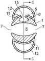
图11是图1导导管的远侧部分在线B-B上的横截面,其中第一设计的未膨胀气囊就位。11 is a cross-section on line B-B of the distal portion of the guide catheter of FIG. 1 with the uninflated balloon of the first design in place.
图12是图1的导管的远侧部分在线B-B上的横截面,其中第二设计的未膨胀气囊就位。12 is a cross-section on line B-B of the distal portion of the catheter of FIG. 1 with the uninflated balloon of the second design in place.
图13是导管的替代实施例的等距视图。Figure 13 is an isometric view of an alternate embodiment of a catheter.
具体实施方式Detailed ways
图1示出了具有轴1的导尿管。导管轴具有近侧端2。近侧端旨在当使用导管时位于身体外部。导管具有远侧端3。远侧端旨在当使用导管时位于使用者的膀胱中。导管的远侧端终止于末端4。在导管的远侧端中限定两个开口。膨胀开口5旨在使可以附接到导管的气囊膨胀。膨胀开口与沿着轴延伸的膨胀管腔6连通。引流开口7旨在从使用者的膀胱排出尿液。引流开口与沿着轴延伸的引流管腔8连通。在导管的远侧端中可以存在多个引流开口。优选地,每个引流开口与引流管腔8连通。图2示出了轴在图1的线A-A上的横截面,示出了管腔6、8。在轴的近侧端处,膨胀开口与膨胀端口9连通,并且引流开口与引流端口10连通。流体可以通过膨胀端口9引入,然后通过膨胀开口5。通过引流开口7接收的尿液可以通过引流端口10来收集。收集容器可以附接到引流端口。FIG. 1 shows a urinary catheter with
在图中所示的示例中,膨胀开口5和引流开口7在导管的纵向轴线上重叠。可能存在多个膨胀开口。该膨胀开口或每个膨胀开口可以位于引流开口或引流开口的子集或所有引流开口的远侧。该膨胀开口或每个膨胀开口可以位于引流开口或引流开口的子集或所有引流开口的近侧。将导管轴配置为使得膨胀开口在纵向方向上不与引流开口重叠可以有助于提高轴的强度。In the example shown in the figures, the
整个远侧端可以向末端逐渐变细,或者远侧端的远侧端部分可以向末端变细;或者远侧端可以围绕导管的纵向轴线具有恒定的直径,在这种情况下,末端可以是大致半球形的。The entire distal end may taper distally, or the distal end portion of the distal end may taper distally; or the distal end may have a constant diameter around the longitudinal axis of the catheter, in which case the tip may be approximately hemispherical.
图3是轴的远侧部分3在图1中B-B线上的横截面,其中轴上安装了部分膨胀的气囊(图1中未示出)。图4是图3的线C-C上的横截面,图5是示出部分膨胀的气囊的等距视图。图2的导管具有两个引流开口7。气囊通常为具有内壁11和外壁12的管的形式。管通常是细长的,在端部13、14之间延伸。气囊由弹性片材制成。管构成管道的壁是弹性的和/或柔性的部分或全部。除了在其一个端部(端部13)附近的孔15之外,气囊被密封,气囊的内部通过孔15与膨胀开口5连通。气囊围绕膨胀开口密封到导管的轴1。因此,可以通过经由孔15将比如水或空气的流体引入到气囊中来使气囊膨胀。管状形式的气囊在导管的末端4上延伸。气囊围绕末端4弯曲。气囊的远离孔15的端部14也附接到导管轴的远侧端。这就使气囊在末端上弯曲。Figure 3 is a cross-section of the distal portion 3 of the shaft on line B-B in Figure 1 with a partially inflated balloon (not shown in Figure 1 ) mounted on the shaft. Figure 4 is a cross section on line C-C of Figure 3, and Figure 5 is an isometric view showing a partially inflated balloon. The catheter of FIG. 2 has two
图4是导管的远侧部分在线C-C上的横截面。图4示出了处于其部分膨胀状态的气囊。图4以点划线示出了插入了导管的人的尿道16和膀胱壁17;而虚线18表示处于其完全膨胀状态的气囊的外部形式。应当注意的是,在其完全膨胀的状态下,气囊可能能够进一步膨胀(即,过度膨胀)。完全膨胀状态是通常将其留置在患者的膀胱中的状态。在其完全膨胀状态下,其外壁从导管的轴径向向外延伸的气囊的尺寸阻止导管通过尿道抽出。这将导管的远侧端保持在膀胱中。气囊还可以在膀胱的底部形成密封,以阻止尿液通过导管泄漏。Figure 4 is a cross-section of the distal portion of the catheter on line C-C. Figure 4 shows the balloon in its partially inflated state. Figure 4 shows in dashed-dotted lines the
在使用导管之前,可以将含有预定体积的流体的储液器与膨胀端口接合。储液器可以是注射器或袋。一旦导管的末端在膀胱中就位,就可以将流体从储存器挤压到气囊中。预定体积的流体可以使得当贮存器被完全排空时气囊被完全膨胀。可以在膨胀管腔中提供阀,以抵抗膨胀管腔中朝向导管近侧端的流体流动。这可以帮助气囊保持膨胀。A reservoir containing a predetermined volume of fluid can be engaged with the expansion port prior to use of the catheter. The reservoir can be a syringe or a bag. Once the end of the catheter is in place in the bladder, fluid can be squeezed from the reservoir into the balloon. The predetermined volume of fluid may cause the balloon to be fully inflated when the reservoir is fully emptied. A valve may be provided in the inflation lumen to resist fluid flow in the inflation lumen towards the proximal end of the catheter. This helps the air bags stay inflated.
如上所述,气囊是折叠在导管末端的细长管的形式。管的端部在导管的远侧端的任一侧上附接到导管轴。在该实例中,附接点在引流开口的近侧并且在引流开口的任一侧上。在其他实施例中,附接点可以与引流开口重叠或位于其远侧。气囊由弹性片材形成。当气囊膨胀时,片材伸展。气囊的这种布置可以提供以下效果中的任何一个或多个。As mentioned above, the balloon is in the form of an elongated tube folded over the end of the catheter. The ends of the tube are attached to the catheter shaft on either side of the distal end of the catheter. In this example, the attachment points are proximal to the drainage opening and on either side of the drainage opening. In other embodiments, the attachment point may overlap or be located distal to the drainage opening. The airbag is formed of an elastic sheet. When the balloon is inflated, the sheet stretches. This arrangement of airbags may provide any one or more of the following effects.
1.当气囊膨胀时,气囊的外皮沿着导管轴的纵向轴线在导管轴的远侧末端4的远侧延伸,如图4中的19所示。这可以帮助缓冲患者膀胱的壁以防止与末端接触。气囊管在导管末端上折叠的事实意味着存在覆盖末端的气囊的两个壁。当气囊膨胀时,气囊的内壁接触末端,迫使外壁与末端间隔开。1. When the balloon is inflated, the sheath of the balloon extends distally of the distal tip 4 of the catheter shaft along the longitudinal axis of the catheter shaft, as shown at 19 in Figure 4 . This can help cushion the walls of the patient's bladder to prevent contact with the tip. The fact that the balloon tube is folded over the catheter tip means that there are two walls of the balloon covering the tip. When the balloon is inflated, the inner wall of the balloon contacts the tip, forcing the outer wall to be spaced from the tip.
2.当气囊膨胀时,气囊的内壁被压靠在导管的末端和远侧侧壁上。因为导管的外部在其接触气囊处是凸起的,所以导管与气囊之间的接触将凹面引入到气囊的内壁。当气囊膨胀时,导管与气囊之间的这种接合可以帮助阻止气囊从末端滑落。这可以避免在气囊与轴接触的整个长度上将气囊粘附到轴的需要。优选地,气囊在该引流开口或每个引流开口的最远侧点的远侧不粘附到轴。优选地,气囊在该引流开口或每个引流开口的最近侧点的远侧不粘附到轴。2. When the balloon is inflated, the inner wall of the balloon is pressed against the tip and distal sidewall of the catheter. Because the outer portion of the catheter is convex where it contacts the balloon, the contact between the catheter and the balloon introduces a concave surface to the inner wall of the balloon. This engagement between the catheter and the balloon can help prevent the balloon from sliding off the tip when the balloon is inflated. This avoids the need to adhere the bladder to the shaft the entire length of the bladder in contact with the shaft. Preferably, the balloon is not adhered to the shaft distal to the distal-most point of the or each drainage opening. Preferably, the balloon is not adhered to the shaft distal to the proximal-most point of the or each drainage opening.
3.图6是导管的远侧部分在图3的平面上的横截面,示出了处于其完全膨胀状态的气囊。当气囊膨胀时,气囊的外皮在引流开口的侧向延伸,如20处所示。这可以帮助保护患者的膀胱壁不被抽吸到引流开口中。气囊管在引流开口的近侧并且在引流开口的任一侧上附接到导管轴的事实可以促进这种效果。3. Figure 6 is a cross-section of the distal portion of the catheter in the plane of Figure 3, showing the balloon in its fully inflated state. When the balloon is inflated, the skin of the balloon extends laterally of the drainage opening as shown at 20 . This can help protect the patient's bladder wall from being drawn into the drainage opening. This effect may be facilitated by the fact that the balloon tube is attached to the catheter shaft proximal to the drainage opening and on either side of the drainage opening.
4.当气囊膨胀时,引流开口7的近侧端21在导管轴的纵向方向上靠近气囊外壁从导管轴侧向延伸的最近侧点22。该点能够基本上位于膀胱的颈部处。因此,引流开口自身可以靠近膀胱颈部定位。这意味着未排出的尿液聚集在膀胱底部的空间很小。4. When the balloon is inflated, the
现在将更详细地描述气囊的各种配置。Various configurations of airbags will now be described in more detail.
气囊具有未膨胀状态。这可以是当导管被包装以供应给使用者时气囊的状态。其上施加有处于其未膨胀状态的气囊的导管可以包装在内部无菌的密封包装中。The balloon has an uninflated state. This may be the state of the balloon when the catheter is packaged for supply to the user. The catheter with the balloon applied thereon in its uninflated state may be packaged in a sterile inner sealed package.
在未膨胀状态下,气囊可以采取管的形式,例如扁平管,具有大于其宽度的长度。气囊可以具有均匀的宽度,或者其宽度可以沿着其长度变化。In the uninflated state, the balloon may take the form of a tube, such as a flat tube, having a length that is greater than its width. The bladder may have a uniform width, or its width may vary along its length.
导管的轴可以由比如聚氨酯、硅弹性体或乳胶的材料形成。聚氨酯导管轴可以比可比的橡胶导管轴更刚性。这可以允许轴具有更大的尿液承载能力,而不牺牲插入的刚性。The shaft of the catheter may be formed from a material such as polyurethane, silicone elastomer, or latex. Polyurethane catheter shafts can be more rigid than comparable rubber catheter shafts. This may allow for greater urine carrying capacity of the shaft without sacrificing insertion rigidity.
轴和/或引流开口的外表面和/或内表面可以涂覆有水凝胶涂层。这种涂层例如由Covalon Technologies Ltd.生产。将这样的涂层施加到内表面可以导致更光滑的内表面,这可减少结壳。替代的涂层可以例如含有银或呋喃咀啶。The outer and/or inner surfaces of the shaft and/or the drainage opening may be coated with a hydrogel coating. Such coatings are produced, for example, by Covalon Technologies Ltd. Applying such a coating to an inner surface can result in a smoother inner surface, which can reduce crusting. Alternative coatings may, for example, contain silver or furan.
气囊的壁可以由比如聚氨酯、硅弹性体或乳胶的材料形成。气囊的壁可以是弹性的或柔性的或两者都是。气囊的壁可以包括具有比壁的一个或多个其他区域更大的弹性和/或柔性的一个或多个区域。气囊的外表面可以涂覆有抗微生物剂,例如惰性润滑材料(hydromer)。壁可以在其区域上是均匀弹性的,或者其杨氏模量可以在其区域上变化。壁可以是双向均匀弹性的,或者壁的区域可以在不同方向上具有不同的杨氏模量。改变壁在其区域上的杨氏模量可以允许气囊在膨胀时的形状受到控制。气囊的壁可以具有均匀的厚度,或者其可以设置有增厚区域,比如肋。这种增厚区域可以在气囊膨胀时影响气囊的形状。The walls of the balloon may be formed from materials such as polyurethane, silicone elastomer or latex. The walls of the balloon may be elastic or flexible or both. The wall of the balloon may include one or more regions having greater elasticity and/or flexibility than one or more other regions of the wall. The outer surface of the balloon may be coated with an antimicrobial agent, such as an inert hydromer. The wall may be uniformly elastic over its area, or its Young's modulus may vary over its area. The walls can be bi-directionally uniformly elastic, or regions of the walls can have different Young's moduli in different directions. Varying the Young's modulus of the wall over its region can allow the shape of the balloon to be controlled when inflated. The wall of the airbag may have a uniform thickness, or it may be provided with thickened areas, such as ribs. This thickened area can affect the shape of the balloon as it expands.
在其未膨胀状态下,气囊在导管的远侧末端上延伸。气囊的一个或多个区域可以附接到导管的轴。一个附接区域可以环绕膨胀开口5。气囊可以在其面向膨胀开口的壁中具有孔。孔可以与膨胀开口连通。通过这种方式,气囊可以被密封在膨胀开口周围,以允许气囊中的压力通过穿过膨胀开口的流体流动而增加。In its uninflated state, the balloon extends over the distal tip of the catheter. One or more regions of the balloon may be attached to the shaft of the catheter. An attachment area may surround the
在第一种配置中,如图5所示,气囊为在导管末端上弯曲的管的形式。管限定支脚23,支脚23沿着导管的轴的侧部延伸。气囊在末端的任一侧上附接到导管的轴。优选地,附接区域相对于轴在直径上彼此相对,但是其可以是偏移的。优选地,附接区域与导管的末端等距,但是其可以与末端相距不同的距离。气囊可以通过粘合剂、通过焊接(例如,热焊接)或通过机械固定件(比如配置为将气囊夹持到导管轴的外部的轴圈)附接到轴。轴圈可以用于将气囊固定到轴的目的。其可以通过气囊和轴之间的粘合剂或焊接来补充。轴圈可以用于改善气囊的膨胀的目的。轴圈可以在该膨胀开口或每个膨胀开口的近侧环绕气囊,从而抑制气囊的近侧部分的膨胀。这可以改善膨胀气囊的形状。图7示出了一种布置。气囊的支脚23在区域24中在引流开口7的近侧附接到导管的轴。支脚中的第一个的侧边缘以25表示。支脚中的另一个的侧边缘用26表示。在该示例中,第一支脚在附接区域24中与另一支脚重叠。这可以有助于促进气囊在膨胀时在围绕引流开口的边缘25、26之间采用一定尺寸的通道,该尺寸允许尿液流入引流开口,但是该尺寸足够小,从而有助于防止膀胱壁被吸入引流开口。在另一个实施例中,气囊的两个支脚在沿着圆周的两侧相遇。在另一个实施例中,两个支脚在一个或两个尿液引流端口的相对边缘处相遇。这些端口可以比支脚的附件更向远侧延伸,以增强尿液引流。In a first configuration, shown in Figure 5, the balloon is in the form of a tube that is bent over the end of the catheter. The tube defines
可以存在一个、两个或更多个引流开口。优选地,当气囊沿着导管轴的侧部延伸时,在气囊的每个支脚之间存在引流开口。There may be one, two or more drainage openings. Preferably, there is a drainage opening between each leg of the balloon as the balloon extends along the side of the catheter shaft.
可以存在一个、两个或更多的膨胀开口。气囊可以从单个端部或从多个端部膨胀。There may be one, two or more expansion openings. The balloon can be inflated from a single end or from multiple ends.
期望当气囊完全膨胀时,气囊的外表面具有以下特性。When the air bag is fully inflated, the outer surface of the air bag is expected to have the following properties.
(i)在该引流开口周围或每个引流开口周围与导管轴间隔开,以阻止膀胱壁被吸入引流开口。(i) Spaced from the catheter shaft around the or each drainage opening to prevent the bladder wall from being drawn into the drainage opening.
(ii)为该引流开口或每个引流开口限定位于该引流开口外侧的通道,尿液可以通过该通道从膀胱空间流入引流开口。(ii) defining for the or each drainage opening a channel outside the drainage opening through which urine can flow from the bladder space into the drainage opening.
已经发现,如果气囊粘附到导管轴的区域具有以下特性中的任何一个或多个,这些特性就会得到提升:It has been found that these properties are improved if the area where the balloon adheres to the catheter shaft has any one or more of the following properties:
-其各自全部或部分地位于处于它们之间的引流开口近侧端的近侧;- each of which is located in whole or in part proximal to the proximal end of the drainage opening between them;
-其在处于它们之间的任何引流开口的近侧重叠。- It overlaps proximally of any drainage openings between them.
这种类型的布置在图7中示出。An arrangement of this type is shown in FIG. 7 .
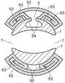
在图2至图7的导管中,气囊是细长管,当折叠在导管末端上时,该细长管具有两条支脚。替代地,气囊可以是分支的,并且可以具有沿着导管轴的侧部延伸的两个以上的支脚。在另一配置中,如图8所示,气囊为T形管的形式。管的中心元件在导管形成支脚27、28的末端上弯曲。在支脚27的近侧端处,管具有一对交叉元件29。当气囊膨胀时,这些交叉元件围绕导管的轴1延伸。交叉元件可以帮助膨胀的气囊密封在膀胱的颈部周围。气囊可以在支脚27、28的近侧端处的位置30、31处附接到导管轴。其他配置是可能的。交叉元件可以从气囊的两条支脚延伸。气囊的支脚可以具有从其延伸的单个交叉元件。In the catheters of Figures 2-7, the balloon is an elongated tube having two legs when folded over the catheter tip. Alternatively, the balloon may be branched and may have more than two legs extending along the sides of the catheter shaft. In another configuration, shown in Figure 8, the balloon is in the form of a T-tube. The central element of the tube is bent on the ends of the
期望在气囊的近侧端(当膨胀时)与该引流开口或每个引流开口的近侧端之间存在相对小的间隔。这促进了膀胱的相对完全的引流。为此,优选的是,气囊的外皮的近侧自由区域(即,未直接粘附到导管轴的外部皮肤的近侧部分)位于该引流开口或每个引流开口的最近侧部分的近侧0至10mm之间,更优选地位于该引流开口或每个引流开口的最近侧部分的近侧2至8mm之间。It is desirable that there is a relatively small separation between the proximal end of the balloon (when inflated) and the proximal end of the or each drainage opening. This promotes relatively complete drainage of the bladder. For this reason, it is preferred that the proximal free area of the outer skin of the balloon (ie, the proximal portion of the outer skin that is not directly adhered to the catheter shaft) is located proximal to the most proximal portion of the or each drainage opening. between 10 mm, more preferably between 2 and 8 mm proximal of the most proximal portion of the or each drainage opening.
期望阻止气囊从导管末端脱出,特别是当气囊处于膨胀状态时。这可以通过多种方式来促进。首先,气囊可以配置为使得在其未膨胀状态和/或在其完全膨胀状态下,沿着导管轴延伸的气囊的每个支脚在围绕轴的纵向轴线的大于90度的弧周围接触导管轴。在这种配置中,气囊的内表面可以采用围绕轴的凹部,该凹部物理地阻止气囊从轴移出。弧可以更优选地大于110度或大于130度或大于150度。这可以通过使气囊的相应支脚在围绕轴的纵向轴线的大于90度、大于110度、大于150度或大于180度的弧周围粘附到轴上来实现。第二,可以处理纵向地位于导管末端与气囊的一部分的附接区域之间的导管轴的区域,以增加其与气囊的摩擦。例如,与导管轴的其余部分相比,它可以是粗糙的,或者它可以涂覆有或由比如橡胶的相对高摩擦的材料形成。第三,气囊可以在引流开口的远侧附接到导管轴,例如通过粘合或焊接。自由区域之间的纵向距离的比值在1.5:1的范围内时,气囊可以自然地倾向于保持在末端上的适当位置。该比率例如可以在1:1至2.5:1的范围中。为了辅助该效果,优选地,导管轴从紧邻引流开口远侧的区域朝向末端平滑地变细。It is desirable to prevent the balloon from dislodging from the catheter tip, especially when the balloon is in the inflated state. This can be facilitated in a number of ways. First, the balloon may be configured such that, in its uninflated state and/or in its fully inflated state, each leg of the balloon extending along the catheter shaft contacts the catheter shaft around an arc greater than 90 degrees about the longitudinal axis of the shaft. In this configuration, the inner surface of the bladder may employ a recess around the shaft that physically prevents the bladder from moving out of the shaft. The arc may more preferably be greater than 110 degrees or greater than 130 degrees or greater than 150 degrees. This can be accomplished by adhering the respective feet of the airbag to the shaft around an arc greater than 90 degrees, greater than 110 degrees, greater than 150 degrees, or greater than 180 degrees around the longitudinal axis of the shaft. Second, the area of the catheter shaft lying longitudinally between the catheter tip and the attachment area of a portion of the balloon can be treated to increase its friction with the balloon. For example, it may be rough compared to the rest of the catheter shaft, or it may be coated or formed from a relatively high friction material such as rubber. Third, the balloon can be attached to the catheter shaft distal to the drainage opening, for example by gluing or welding. With a ratio of longitudinal distances between free areas in the range of 1.5:1, the airbag may naturally tend to remain in place on the tip. The ratio may be in the range of 1:1 to 2.5:1, for example. To assist this effect, preferably, the catheter shaft tapers smoothly from a region immediately distal to the drainage opening towards the tip.
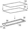
气囊可以由弹性材料的连续管形成。管可以被挤压或拉伸成一定形状。替代地,管可以由单片材料形成,该单片材料被折叠以使其侧边缘会合,然后侧边缘接合在一起。图9和图10示出了可以制造导管的其他方式。The balloon may be formed from a continuous tube of elastic material. Tubes can be extruded or stretched into shape. Alternatively, the tube may be formed from a single piece of material that is folded so that its side edges meet and then the side edges are joined together. 9 and 10 illustrate other ways in which the catheter may be fabricated.
在图9的方法中,气囊由两个弹性材料片50、51形成。片51限定了孔52。一片放置在另一片的顶部上,并且片围绕其周缘接合在一起,如53处所示。这可以例如通过粘合剂或通过焊接来完成。在该示例中,片是细长的并且具有均匀的宽度,导致气囊为均匀宽度的管的形式,但是片可以具有其他形状。在其中一个已经限定孔52的片材已经焊接在一起之后,将气囊附接到导管轴。气囊通过围绕膨胀开口5连续地将孔52的周缘接合到轴而附接到轴。这在气囊的内部和膨胀管腔之间形成不透流体的密封。气囊缠绕在导管的末端上,并进一步在轴的与膨胀开口相对的侧部上附接到轴。在图10的方法中,气囊由两个弹性材料的片54、55形成。在该阶段,两个板都不限定孔。如56所示,片围绕它们的周缘接合在一起,在57处留下开口,通过该开口可以进入片之间的区域。然后,通过将片55的外表面的一部分围绕膨胀开口5连续地粘附到轴上,将气囊附接到轴上。然后,通过开口57引入工具以刺穿片55,片55在此处与膨胀开口重叠。然后,通过跨越开口将片54、55接合在一起来密封开口57。除了其通过工具穿透的孔连接到膨胀管腔之外,这封闭了气囊以形成不透流体的空间。气囊缠绕在导管的末端上,并进一步在轴的与膨胀开口相对的侧部上附接到轴。In the method of FIG. 9 , the airbag is formed from two
总之,在图9的方法中,在气囊附接到导管轴之前形成用于与膨胀开口连通的孔,并且在图10的方法中,在气囊附接到导管轴之后形成用于与膨胀开口连通的孔。In summary, in the method of Fig. 9, the hole for communication with the inflation opening is formed before the balloon is attached to the catheter shaft, and in the method of Fig. 10, the hole for communication with the inflation opening is formed after the balloon is attached to the catheter shaft hole.
在上面参考图10描述的方法中,导管设置有膨胀开口,气囊围绕膨胀开口附接到导管,并且使用工具在膨胀开口的位置刺穿气囊。在替代的过程中,可以在没有膨胀开口的情况下设置导管,并且在气囊已经附接到导管之后,工具可以刺穿气囊和导管壁两者。In the method described above with reference to Figure 10, a catheter is provided with an inflation opening, a balloon is attached to the catheter around the inflation opening, and a tool is used to pierce the balloon at the location of the inflation opening. In an alternative procedure, the catheter may be provided without the inflation opening, and the tool may pierce both the balloon and the catheter wall after the balloon has been attached to the catheter.
因此,在该替代方法中,该方法可以包括设置具有近侧端和远侧端的轴,远侧端终止于末端,引流开口位于轴的远侧端,引流开口与轴的引流管腔连通;设置具有通向其内部的进入开口的弹性壁管道;将管道的壁固定到轴;通过进入开口引入工具;利用工具刺穿管道的壁;刺穿轴以形成位于轴的远侧端的膨胀开口,膨胀开口与轴的膨胀管腔连通;关闭进入开口。Thus, in this alternative method, the method may include providing a shaft having a proximal end and a distal end, the distal end terminating at the tip, a drainage opening at the distal end of the shaft, the drainage opening being in communication with a drainage lumen of the shaft; providing Resilient walled conduit with access opening to its interior; securing wall of conduit to shaft; introducing tool through access opening; piercing wall of conduit with tool; piercing shaft to form expansion opening at distal end of shaft, expanding The opening communicates with the inflation lumen of the shaft; the access opening is closed.
在另一替代过程中,冲头可以用于不仅通过气囊形成通向膨胀管腔的通路,而且然后在气囊的一个壁中冲出孔。然后可以在气囊中的孔周围施加胶,并且气囊的该部分可以被呈现给轴以将其固定。In another alternative process, a punch may be used to not only create access to the inflation lumen through the balloon, but then punch a hole in one of the walls of the balloon. Glue can then be applied around the hole in the balloon and this portion of the balloon can be presented to the shaft to secure it.
当气囊由两个材料片形成时,其可以是相同材料或不同材料的片。当片是不同材料时,它们可以都是弹性材料,或者形成内壁的片可以是相对非弹性材料的片,而形成外壁的片材可以是相对弹性材料的片。When the airbag is formed from two sheets of material, they may be sheets of the same material or different materials. When the sheets are of different materials, they may both be elastic materials, or the sheet forming the inner wall may be a sheet of relatively inelastic material and the sheet forming the outer wall may be a sheet of relatively elastic material.
现在将描述气囊可以在其未膨胀状态下设置的方式。The manner in which the airbag can be arranged in its uninflated state will now be described.
图11是图1中B-B线的横截面,其中未膨胀的气囊在导管轴上就位。在该示例中,气囊被压靠在轴上,以限定内壁58和外壁59。内壁58可以固定到导管轴上。壁沿着它们的侧边缘接合在一起,如60处所示。内壁在区域61处围绕膨胀开口密封到轴。Figure 11 is a cross-section through line B-B of Figure 1 with the uninflated balloon in place on the catheter shaft. In this example, the bladder is pressed against the shaft to define an
图12是在与图11类似的平面上的横截面。图12示出了其侧边缘被折叠在气囊的外层下面的气囊。处于未膨胀状态的气囊的最外层用62表示。气囊的侧边缘63远离最外层62折叠。侧边缘位于外层62与导管轴1之间。侧边缘包括气囊的两个层。因此,当气囊膨胀时,侧边缘从最外层62下方向外膨胀。这可以允许气囊比在图11的布置中更自由地膨胀。以这种方式设置附加的气囊材料可以允许对于给定程度的拉伸气囊采用比其原本采用的尺寸更大的尺寸。在图12的布置中,在覆盖导管杆的一些点处存在多于两个厚度的气囊材料。气囊在区域64处密封到膨胀开口周围的轴上。FIG. 12 is a cross-section in a plane similar to that of FIG. 11 . Figure 12 shows the airbag with its side edges folded under the outer layers of the airbag. The outermost layer of the balloon in its uninflated state is indicated at 62 . The side edges 63 of the airbag are folded away from the
图7示出了具有这种向下折叠配置的气囊。从图12可以看出,向下折叠的侧边缘63在其中心端终止于折叠线65。这些折叠线在图7中示出。如图7所示,气囊在最外层下折叠的部分的宽度可以朝向导管轴的末端增加。已经发现,这有助于促进处于膨胀状态的期望形式的气囊。Figure 7 shows an airbag with this folded-down configuration. As can be seen in Figure 12, the downwardly folded
图13示出了气囊处于膨胀状态的尿液气囊导管的另一个实施例。导管的远侧端总体上以70示出。导管的轴71包括膨胀管腔72和引流管腔73。它们以与图1所示相同的方式沿着导管的轴朝向近侧端延伸。在远侧端,膨胀管腔终止于膨胀开口74,而引流管腔终止于引流开口75。总体上以76表示的气囊位于导管的远侧端。气囊配置为具有多个侧通道77、78、79,当膨胀时,这些侧通道将在导管的纵向方向上从导管的轴上在末端近侧的相应附接点80、81延伸到区域82,在区域82处,通道接合并相互连通。至少一个通道(在该示例中为通道77)与该膨胀端口或膨胀端口连通。通道的近侧端是密封的。可以通过其发生膨胀的该通道或每个通道被密封在相应的膨胀开口周围。气囊被配置为使得相互连通区域82位于导管末端的远侧。在一个示例中,侧通道可以配置为使得当气囊膨胀时,限定相互连通区域82的材料的内壁83接触导管的末端。在这种情况下,引流开口可以位于导管轴的侧部,如图1至图12的实施例。替代地,侧通道可以配置为使得当气囊膨胀时,限定相互连通区域82的材料的内壁83与导管的末端间隔开。这在图13中示出。在这种情况下,引流开口可以位于导管的末端,如图13所示。该引流开口位于导管的末端中。引流开口从末端向远侧开放。这可以具有许多优点。将引流开口定位在导管的末端可以允许更便宜的制造,因为引流管腔可以简单地沿着导管轴纵向延伸。导管末端处的引流开口可能较不易于在开口周围结壳。通道从导管轴侧向延伸并且可以帮助保持膀胱粘膜不接触轴。可以存在两个、三个或更多个侧通道。在其未膨胀状态下,气囊可以覆盖或伸展在导管的末端上,由附接点80、81保持。Figure 13 shows another embodiment of a urine balloon catheter with the balloon in an inflated state. The distal end of the catheter is shown generally at 70 . The
气囊最初可以采用未膨胀状态。在其未膨胀状态下,气囊的外表面可以与导管的外表面紧密贴合。这可以便于将导管插入使用者的膀胱中。在未膨胀状态下,气囊可以抵靠导管的外表面拉紧。在未膨胀状态下,气囊的材料可以包装在引流管腔中。例如,在图13的气囊的未膨胀状态下,互连区域82的材料可以驻留在已经穿过引流开口的引流管腔中。这可以允许保持处于其未膨胀状态的气囊的自由材料,使得其在导管外部不松动。这可以有助于将导管插入使用者体内。在图13的示例中,引流开口的直径可以大于导管轴的平均直径的50%和/或导管轴的在气囊到导管轴的附连的最近侧点远侧的部分的平均直径的50%。The balloon may initially assume an uninflated state. In its uninflated state, the outer surface of the balloon may be in close contact with the outer surface of the catheter. This may facilitate insertion of the catheter into the user's bladder. In the uninflated state, the balloon may be tensioned against the outer surface of the catheter. In the uninflated state, the balloon material can be packaged in the drainage lumen. For example, in the uninflated state of the balloon of Figure 13, the material of the
在任何实施例中,导管轴的外表面可以限定未膨胀气囊可以位于其中的凹部。凹部的尺寸可以设置为使得未膨胀气囊的外部与导管的暴露表面齐平。这可以帮助导管通过尿道插入。形成气囊的材料可以具有自粘附的倾向,这可以有助于将其保持在其折叠和/或压缩状态直到其膨胀。这可以帮助导管通过尿道插入。In any embodiment, the outer surface of the catheter shaft can define a recess in which the uninflated balloon can be located. The recess may be sized such that the exterior of the uninflated balloon is flush with the exposed surface of the catheter. This helps the catheter be inserted through the urethra. The balloon-forming material may have a tendency to self-adhere, which may help hold it in its folded and/or compressed state until it expands. This helps the catheter be inserted through the urethra.
在任何实施例中,可以在气囊上设置附加的材料层。例如,可以在气囊上设置附加的网,以便在气囊膨胀时使导管远侧端的外表面平滑。替代地或附加地,可以存在位于上述气囊远侧和/或侧向外侧的另外的气囊。In any embodiment, additional layers of material may be provided on the airbag. For example, additional mesh may be placed on the balloon to smooth the outer surface of the distal end of the catheter when the balloon is inflated. Alternatively or additionally, there may be additional balloons located distally and/or laterally outboard of the aforementioned balloons.
本申请人在此相互独立地公开了本文描述的各个特征以及两个或更多个这样的特征的任意组合,以至于这些特征或组合能够基于本说明书作为整体根据本领域技术人员的公知常识来进行,而不管这些特征或特征的组合是否解决了这里公开的任意问题,并且不限于权利要求的范围。申请人指出,本发明的各方面可以由任何这样的单独特征或特征组合组成。鉴于前面的描述,对于本领域技术人员显而易见的是,可以在本发明的范围内进行各种修改。The applicant hereby discloses, independently of one another, individual features described herein, and any combination of two or more of such features, such that these features or combinations can be derived from the common general knowledge of a person skilled in the art based on this description as a whole. performed regardless of whether such feature or combination of features solves any of the problems disclosed herein, and is not intended to limit the scope of the claims. Applicants indicate that aspects of the invention may consist of any such individual feature or combination of features. In view of the foregoing description, it will be apparent to those skilled in the art that various modifications can be made within the scope of the present invention.
Claims (20)
Applications Claiming Priority (3)
| Application Number | Priority Date | Filing Date | Title |
|---|---|---|---|
| GB1701027.3 | 2017-01-20 | ||
| GB1701027.3AGB2558930A (en) | 2017-01-20 | 2017-01-20 | Urinary catheter |
| PCT/GB2018/050136WO2018134591A1 (en) | 2017-01-20 | 2018-01-18 | Urinary catheter |
Publications (2)
| Publication Number | Publication Date |
|---|---|
| CN110603070A CN110603070A (en) | 2019-12-20 |
| CN110603070Btrue CN110603070B (en) | 2022-08-16 |
Family
ID=58463172
Family Applications (1)
| Application Number | Title | Priority Date | Filing Date |
|---|---|---|---|
| CN201880012796.9AActiveCN110603070B (en) | 2017-01-20 | 2018-01-18 | Catheter |
Country Status (11)
| Country | Link |
|---|---|
| US (3) | US11446468B2 (en) |
| EP (1) | EP3570924B8 (en) |
| JP (1) | JP7036836B2 (en) |
| CN (1) | CN110603070B (en) |
| AU (1) | AU2018209337B2 (en) |
| CA (1) | CA3050617A1 (en) |
| ES (1) | ES2959249T3 (en) |
| GB (2) | GB2558930A (en) |
| MX (1) | MX2019008667A (en) |
| MY (1) | MY196061A (en) |
| WO (1) | WO2018134591A1 (en) |
Families Citing this family (15)
| Publication number | Priority date | Publication date | Assignee | Title |
|---|---|---|---|---|
| WO2009135141A1 (en) | 2008-05-01 | 2009-11-05 | Bristol-Myers Squibb Company | Rectal drain appliance |
| CN108578044A (en) | 2011-03-17 | 2018-09-28 | 康沃特克科技公司 | High barrier elastomer excrement conduit or ostomy bag |
| PL3027266T3 (en) | 2013-08-01 | 2023-09-04 | Convatec Technologies Inc. | Self-closing bag connector |
| GB2517698A (en)* | 2013-08-27 | 2015-03-04 | John Spencer Havard | The Holey Catheter is a retained urethral device that allows complete bladder emptying. Mucosal damage is less with a shorter intra-vesical tube |
| GB201721956D0 (en) | 2017-12-27 | 2018-02-07 | Convatec Ltd | Female catheter locator tip |
| GB201721955D0 (en) | 2017-12-27 | 2018-02-07 | Convatec Ltd | Catheter wetting devices |
| USD908865S1 (en) | 2018-08-17 | 2021-01-26 | Emmy Medical, Llc | Catheter |
| CN110960781B (en)* | 2018-09-27 | 2025-02-11 | 康路联(无锡)医疗科技有限公司 | Catheterization structure |
| CN110960782A (en)* | 2018-09-27 | 2020-04-07 | 上海先艺医疗科技有限公司 | Structure of urethral catheterization product |
| US11607531B2 (en) | 2019-05-09 | 2023-03-21 | Neuravi Limited | Balloon catheter with venting of residual air in a proximal direction |
| US11931522B2 (en)* | 2019-05-09 | 2024-03-19 | Neuravi Limited | Inflation lumen kink protection and balloon profile |
| CA3140906A1 (en) | 2019-06-11 | 2020-12-17 | Convatec Technologies Inc. | Urine collection bags for use with catheter products, kits incorporating the same, and methods therefor |
| WO2020256865A1 (en) | 2019-06-21 | 2020-12-24 | Purewick Corporation | Fluid collection devices including a base securement area, and related systems and methods |
| CN114375187A (en)* | 2019-07-11 | 2022-04-19 | 普奥维克有限公司 | Fluid collection devices, systems, and methods |
| GB2606750B (en) | 2021-05-19 | 2024-10-02 | The Flume Catheter Company Ltd | Urinary catheter and methods of manufacture |
Citations (9)
| Publication number | Priority date | Publication date | Assignee | Title |
|---|---|---|---|---|
| US3438375A (en)* | 1966-03-18 | 1969-04-15 | Kendall & Co | Non-traumatic retention catheter |
| EP1142530A1 (en)* | 2000-03-21 | 2001-10-10 | Rainer Dr. Zotz | Pneumatic drive for an endoscope |
| US6607546B1 (en)* | 2000-09-01 | 2003-08-19 | Roger E. Murken | Nasal catheter |
| WO2007005734A2 (en)* | 2005-07-01 | 2007-01-11 | C.R. Bard, Inc. | Indwelling urinary drainage catheter |
| CN200945301Y (en)* | 2006-09-08 | 2007-09-12 | 刘书勇 | Disposable injecting device for urethra anaesthesia |
| CN101795629A (en)* | 2007-05-21 | 2010-08-04 | Aoi医药公司 | Articulating cavitation device |
| CN201949487U (en)* | 2011-02-21 | 2011-08-31 | 张国学 | Double balloon catheter convenient to insert |
| CN102908715A (en)* | 2012-11-02 | 2013-02-06 | 王亮 | Contact limiting type double-saccule three-cavity catheter |
| WO2014197924A1 (en)* | 2013-06-14 | 2014-12-18 | Perfusion Solutions Pty Ltd | Cardiac function evaluation system |
Family Cites Families (44)
| Publication number | Priority date | Publication date | Assignee | Title |
|---|---|---|---|---|
| AU5722173A (en) | 1972-07-04 | 1975-01-09 | Stanley Francis Duturbure | Catheter tube |
| US3811448A (en) | 1972-10-25 | 1974-05-21 | A Morton | Urinary drainage catheter |
| US3954110A (en) | 1974-01-24 | 1976-05-04 | Hutchison Ernest L | Retention catheter with bilobate balloon |
| FR2392680A1 (en)* | 1977-05-30 | 1978-12-29 | Rocco Francesco | BALLOON TYPE CATHETER |
| US4222384A (en) | 1977-11-09 | 1980-09-16 | Biomedical Engineering Associates, Inc. | Catheter |
| US4351342A (en)* | 1981-06-10 | 1982-09-28 | Wiita Bruce E | Balloon catheter |
| US5042976A (en) | 1987-01-13 | 1991-08-27 | Terumo Kabushiki Kaisha | Balloon catheter and manufacturing method of the same |
| US4762130A (en)* | 1987-01-15 | 1988-08-09 | Thomas J. Fogarty | Catheter with corkscrew-like balloon |
| GB9014187D0 (en) | 1990-06-26 | 1990-08-15 | Brown John J | Self retaining urinary catheter |
| US5308325A (en)* | 1991-01-28 | 1994-05-03 | Corpak, Inc. | Retention balloon for percutaneous catheter |
| NL9201724A (en)* | 1991-10-07 | 1993-05-03 | Medrad Inc En The Trustees Of | PROBE FOR MRI IMAGING AND SPECTROSCOPY, ESPECIALLY IN THE CERVICAL AREA. |
| US5250029A (en) | 1991-11-06 | 1993-10-05 | Edward Lin | Zero-residual zero-tip balloon catheter |
| US5401241A (en)* | 1992-05-07 | 1995-03-28 | Inamed Development Co. | Duodenal intubation catheter |
| US20030032963A1 (en)* | 2001-10-24 | 2003-02-13 | Kyphon Inc. | Devices and methods using an expandable body with internal restraint for compressing cancellous bone |
| JP2653418B2 (en)* | 1994-08-19 | 1997-09-17 | 広島大学長 | Cardiopulmonary support equipment |
| US6063056A (en)* | 1998-06-29 | 2000-05-16 | Engelberg; Moshe | Device and method for atraumatic dilatation |
| ES2268038T3 (en) | 2001-04-16 | 2007-03-16 | Cytyc Corporation | MEDICAL INSTRUMENT WITH AN ATRAUMATIC END. |
| US20080071250A1 (en) | 2003-04-03 | 2008-03-20 | Crisp William E | Urinary tract catheter |
| AU2011203584B2 (en)* | 2003-09-09 | 2013-07-11 | Convatec Technologies Inc. | Fecal management appliance and method and apparatus for introducing same |
| EP1720595B1 (en)* | 2004-03-03 | 2011-05-11 | C.R.Bard, Inc. | Loop-tip catheter |
| WO2005102219A2 (en)* | 2004-04-20 | 2005-11-03 | Musc Foundation For Research Development | Intravascular medical device |
| IL161554A0 (en)* | 2004-04-22 | 2004-09-27 | Gali Tech Ltd | Catheter |
| US7914497B2 (en) | 2005-01-26 | 2011-03-29 | Radius International Limited Partnership | Catheter |
| US8551043B2 (en)* | 2006-04-21 | 2013-10-08 | C. R. Bard, Inc. | Feeding device and bolster apparatus and method for making the same |
| US20080097300A1 (en)* | 2006-08-07 | 2008-04-24 | Sherif Eskaros | Catheter balloon with multiple micropleats |
| US20080221552A1 (en)* | 2007-03-09 | 2008-09-11 | Abbott Cardiovascular Systems Inc. | Agent delivery perfusion catheter |
| US8409171B2 (en) | 2008-02-28 | 2013-04-02 | Hollister Incorporated | Fluid drainage catheter having an external flow path |
| EP2147695B1 (en)* | 2008-07-23 | 2011-11-30 | Abbott Laboratories Vascular Enterprises Limited | Balloon of a balloon catheter |
| ITMI20080348U1 (en) | 2008-10-20 | 2010-04-21 | Francesco Rocco | CATHETER STRUCTURE. |
| DE102008060162A1 (en) | 2008-12-02 | 2010-06-10 | Carl Zeiss Surgical Gmbh | Balloon catheter and applicator with balloon catheter |
| EP2431066B1 (en)* | 2009-05-14 | 2014-02-12 | Terumo Kabushiki Kaisha | Method of manufacturing balloon catheter and balloon catheter |
| US8636724B2 (en) | 2009-10-26 | 2014-01-28 | Poiesis Medical, Llc | Balloon encapsulated catheter tip |
| FR2961683B1 (en) | 2010-06-23 | 2013-11-29 | Assist Publ Hopitaux De Paris | CANNULA FOR REALIZING REGIONAL EXTRACORPOREAL CIRCULATION |
| JP5489881B2 (en) | 2010-06-28 | 2014-05-14 | 株式会社カネカ | Stent delivery catheter |
| US20120203210A1 (en) | 2011-02-07 | 2012-08-09 | Schanz Richard W | Urinary catheter and method |
| JP6101681B2 (en)* | 2012-03-15 | 2017-03-22 | テルモ株式会社 | Balloon catheter and stent delivery system |
| NZ702283A (en)* | 2012-06-06 | 2016-09-30 | Loma Vista Medical Inc | Inflatable medical devices |
| GB2517698A (en) | 2013-08-27 | 2015-03-04 | John Spencer Havard | The Holey Catheter is a retained urethral device that allows complete bladder emptying. Mucosal damage is less with a shorter intra-vesical tube |
| JP2015061551A (en)* | 2013-09-21 | 2015-04-02 | 住友ベークライト株式会社式会社 | Guide tube for endoscope |
| US9440043B2 (en) | 2014-06-13 | 2016-09-13 | Leading Age Supplies LLC | Catheter having a tapered structure and balloon formed above a lower drainage hole |
| CA2956128C (en)* | 2014-09-25 | 2023-02-21 | Merit Medical Systems, Inc. | Coated balloons and coated balloon assemblies and related methods of use and manufacture |
| WO2016200490A1 (en)* | 2015-06-08 | 2016-12-15 | Endovention, Inc. | Method and apparatus for allowing inflation of inflatable elements within medical devices |
| US11247028B2 (en)* | 2015-10-16 | 2022-02-15 | The Regents Of The University Of California | Device for global and targeted delivery of brachytherapy to the bladder lumen |
| SE540534C2 (en)* | 2016-03-17 | 2018-09-25 | Madeleine Ramstedt | Urinary catheter comprising an inflatable retention member |
- 2017
- 2017-01-20GBGB1701027.3Apatent/GB2558930A/ennot_activeWithdrawn
- 2018
- 2018-01-17GBGB1800739.3Apatent/GB2559883B/enactiveActive
- 2018-01-18EPEP18701542.5Apatent/EP3570924B8/enactiveActive
- 2018-01-18USUS16/479,701patent/US11446468B2/enactiveActive
- 2018-01-18AUAU2018209337Apatent/AU2018209337B2/enactiveActive
- 2018-01-18JPJP2019560492Apatent/JP7036836B2/enactiveActive
- 2018-01-18MYMYPI2019004181Apatent/MY196061A/enunknown
- 2018-01-18CACA3050617Apatent/CA3050617A1/enactivePending
- 2018-01-18WOPCT/GB2018/050136patent/WO2018134591A1/ennot_activeCeased
- 2018-01-18CNCN201880012796.9Apatent/CN110603070B/enactiveActive
- 2018-01-18MXMX2019008667Apatent/MX2019008667A/enunknown
- 2018-01-18ESES18701542Tpatent/ES2959249T3/enactiveActive
- 2022
- 2022-08-11USUS17/885,778patent/US12214142B2/enactiveActive
- 2025
- 2025-01-03USUS19/009,814patent/US20250135152A1/enactivePending
Patent Citations (9)
| Publication number | Priority date | Publication date | Assignee | Title |
|---|---|---|---|---|
| US3438375A (en)* | 1966-03-18 | 1969-04-15 | Kendall & Co | Non-traumatic retention catheter |
| EP1142530A1 (en)* | 2000-03-21 | 2001-10-10 | Rainer Dr. Zotz | Pneumatic drive for an endoscope |
| US6607546B1 (en)* | 2000-09-01 | 2003-08-19 | Roger E. Murken | Nasal catheter |
| WO2007005734A2 (en)* | 2005-07-01 | 2007-01-11 | C.R. Bard, Inc. | Indwelling urinary drainage catheter |
| CN200945301Y (en)* | 2006-09-08 | 2007-09-12 | 刘书勇 | Disposable injecting device for urethra anaesthesia |
| CN101795629A (en)* | 2007-05-21 | 2010-08-04 | Aoi医药公司 | Articulating cavitation device |
| CN201949487U (en)* | 2011-02-21 | 2011-08-31 | 张国学 | Double balloon catheter convenient to insert |
| CN102908715A (en)* | 2012-11-02 | 2013-02-06 | 王亮 | Contact limiting type double-saccule three-cavity catheter |
| WO2014197924A1 (en)* | 2013-06-14 | 2014-12-18 | Perfusion Solutions Pty Ltd | Cardiac function evaluation system |
Also Published As
| Publication number | Publication date |
|---|---|
| GB201800739D0 (en) | 2018-02-28 |
| AU2018209337A1 (en) | 2019-08-15 |
| WO2018134591A1 (en) | 2018-07-26 |
| AU2018209337A2 (en) | 2019-08-22 |
| US20220387751A1 (en) | 2022-12-08 |
| GB2559883B (en) | 2019-07-10 |
| GB2559883A (en) | 2018-08-22 |
| US20200384242A1 (en) | 2020-12-10 |
| JP2020505210A (en) | 2020-02-20 |
| MX2019008667A (en) | 2019-11-11 |
| US20250135152A1 (en) | 2025-05-01 |
| US11446468B2 (en) | 2022-09-20 |
| EP3570924B1 (en) | 2023-09-06 |
| AU2018209337B2 (en) | 2022-11-17 |
| CA3050617A1 (en) | 2018-07-26 |
| US12214142B2 (en) | 2025-02-04 |
| ES2959249T3 (en) | 2024-02-22 |
| GB2558930A (en) | 2018-07-25 |
| MY196061A (en) | 2023-03-13 |
| EP3570924B8 (en) | 2023-10-11 |
| EP3570924C0 (en) | 2023-09-06 |
| JP7036836B2 (en) | 2022-03-15 |
| GB201701027D0 (en) | 2017-03-08 |
| CN110603070A (en) | 2019-12-20 |
| EP3570924A1 (en) | 2019-11-27 |
Similar Documents
| Publication | Publication Date | Title |
|---|---|---|
| CN110603070B (en) | Catheter | |
| US11202891B2 (en) | Reinforced balloon catheter | |
| US8636724B2 (en) | Balloon encapsulated catheter tip | |
| JP4621737B2 (en) | Device for closing the natural or colostomy | |
| US11207097B2 (en) | Fluid management device for medical tubes and drainage incisions | |
| US9744069B2 (en) | Device for stool drainage | |
| US8518020B2 (en) | Safety urinary catheter | |
| US9999412B2 (en) | Fistula management device and method | |
| JP2005287809A (en) | Medical tool |
Legal Events
| Date | Code | Title | Description |
|---|---|---|---|
| PB01 | Publication | ||
| PB01 | Publication | ||
| SE01 | Entry into force of request for substantive examination | ||
| SE01 | Entry into force of request for substantive examination | ||
| GR01 | Patent grant | ||
| GR01 | Patent grant |