CN110578770B - Electromagnetic-piezoelectric composite vibration control device based on synchronous switch damping technology - Google Patents
Electromagnetic-piezoelectric composite vibration control device based on synchronous switch damping technologyDownload PDFInfo
- Publication number
- CN110578770B CN110578770BCN201910898079.7ACN201910898079ACN110578770BCN 110578770 BCN110578770 BCN 110578770BCN 201910898079 ACN201910898079 ACN 201910898079ACN 110578770 BCN110578770 BCN 110578770B
- Authority
- CN
- China
- Prior art keywords
- electromagnetic
- piezoelectric
- rigid frame
- guide rod
- guide part
- Prior art date
- Legal status (The legal status is an assumption and is not a legal conclusion. Google has not performed a legal analysis and makes no representation as to the accuracy of the status listed.)
- Active
Links
Images


Classifications
- H—ELECTRICITY
- H10—SEMICONDUCTOR DEVICES; ELECTRIC SOLID-STATE DEVICES NOT OTHERWISE PROVIDED FOR
- H10N—ELECTRIC SOLID-STATE DEVICES NOT OTHERWISE PROVIDED FOR
- H10N30/00—Piezoelectric or electrostrictive devices
- H10N30/20—Piezoelectric or electrostrictive devices with electrical input and mechanical output, e.g. functioning as actuators or vibrators
- H10N30/204—Piezoelectric or electrostrictive devices with electrical input and mechanical output, e.g. functioning as actuators or vibrators using bending displacement, e.g. unimorph, bimorph or multimorph cantilever or membrane benders
- H10N30/2041—Beam type
- H10N30/2042—Cantilevers, i.e. having one fixed end
- H10N30/2045—Cantilevers, i.e. having one fixed end adapted for in-plane bending displacement
- H—ELECTRICITY
- H02—GENERATION; CONVERSION OR DISTRIBUTION OF ELECTRIC POWER
- H02N—ELECTRIC MACHINES NOT OTHERWISE PROVIDED FOR
- H02N2/00—Electric machines in general using piezoelectric effect, electrostriction or magnetostriction
- H02N2/0005—Electric machines in general using piezoelectric effect, electrostriction or magnetostriction producing non-specific motion; Details common to machines covered by H02N2/02 - H02N2/16
- H02N2/005—Mechanical details, e.g. housings
- H02N2/0055—Supports for driving or driven bodies; Means for pressing driving body against driven body
- H02N2/006—Elastic elements, e.g. springs
- F—MECHANICAL ENGINEERING; LIGHTING; HEATING; WEAPONS; BLASTING
- F16—ENGINEERING ELEMENTS AND UNITS; GENERAL MEASURES FOR PRODUCING AND MAINTAINING EFFECTIVE FUNCTIONING OF MACHINES OR INSTALLATIONS; THERMAL INSULATION IN GENERAL
- F16F—SPRINGS; SHOCK-ABSORBERS; MEANS FOR DAMPING VIBRATION
- F16F15/00—Suppression of vibrations in systems; Means or arrangements for avoiding or reducing out-of-balance forces, e.g. due to motion
- F16F15/02—Suppression of vibrations of non-rotating, e.g. reciprocating systems; Suppression of vibrations of rotating systems by use of members not moving with the rotating systems
- F16F15/03—Suppression of vibrations of non-rotating, e.g. reciprocating systems; Suppression of vibrations of rotating systems by use of members not moving with the rotating systems using magnetic or electromagnetic means
- F—MECHANICAL ENGINEERING; LIGHTING; HEATING; WEAPONS; BLASTING
- F16—ENGINEERING ELEMENTS AND UNITS; GENERAL MEASURES FOR PRODUCING AND MAINTAINING EFFECTIVE FUNCTIONING OF MACHINES OR INSTALLATIONS; THERMAL INSULATION IN GENERAL
- F16F—SPRINGS; SHOCK-ABSORBERS; MEANS FOR DAMPING VIBRATION
- F16F15/00—Suppression of vibrations in systems; Means or arrangements for avoiding or reducing out-of-balance forces, e.g. due to motion
- F16F15/005—Suppression of vibrations in systems; Means or arrangements for avoiding or reducing out-of-balance forces, e.g. due to motion using electro- or magnetostrictive actuation means
- H—ELECTRICITY
- H02—GENERATION; CONVERSION OR DISTRIBUTION OF ELECTRIC POWER
- H02N—ELECTRIC MACHINES NOT OTHERWISE PROVIDED FOR
- H02N2/00—Electric machines in general using piezoelectric effect, electrostriction or magnetostriction
- H02N2/0005—Electric machines in general using piezoelectric effect, electrostriction or magnetostriction producing non-specific motion; Details common to machines covered by H02N2/02 - H02N2/16
- H02N2/0075—Electrical details, e.g. drive or control circuits or methods
- H—ELECTRICITY
- H10—SEMICONDUCTOR DEVICES; ELECTRIC SOLID-STATE DEVICES NOT OTHERWISE PROVIDED FOR
- H10N—ELECTRIC SOLID-STATE DEVICES NOT OTHERWISE PROVIDED FOR
- H10N30/00—Piezoelectric or electrostrictive devices
- H10N30/80—Constructional details
- H10N30/802—Circuitry or processes for operating piezoelectric or electrostrictive devices not otherwise provided for, e.g. drive circuits
- H—ELECTRICITY
- H10—SEMICONDUCTOR DEVICES; ELECTRIC SOLID-STATE DEVICES NOT OTHERWISE PROVIDED FOR
- H10N—ELECTRIC SOLID-STATE DEVICES NOT OTHERWISE PROVIDED FOR
- H10N30/00—Piezoelectric or electrostrictive devices
- H10N30/80—Constructional details
- H10N30/88—Mounts; Supports; Enclosures; Casings
- H10N30/886—Additional mechanical prestressing means, e.g. springs
- F—MECHANICAL ENGINEERING; LIGHTING; HEATING; WEAPONS; BLASTING
- F16—ENGINEERING ELEMENTS AND UNITS; GENERAL MEASURES FOR PRODUCING AND MAINTAINING EFFECTIVE FUNCTIONING OF MACHINES OR INSTALLATIONS; THERMAL INSULATION IN GENERAL
- F16F—SPRINGS; SHOCK-ABSORBERS; MEANS FOR DAMPING VIBRATION
- F16F2224/00—Materials; Material properties
- F16F2224/02—Materials; Material properties solids
- F16F2224/0283—Materials; Material properties solids piezoelectric; electro- or magnetostrictive
Landscapes
- Engineering & Computer Science (AREA)
- General Engineering & Computer Science (AREA)
- Physics & Mathematics (AREA)
- Acoustics & Sound (AREA)
- Aviation & Aerospace Engineering (AREA)
- Mechanical Engineering (AREA)
- Electromagnetism (AREA)
- Vibration Prevention Devices (AREA)
Abstract
Description
Translated fromChinese技术领域technical field
本发明涉及振动抑制技术领域,特别是涉及一种基于同步开关阻尼技术的电磁-压电复合振动控制装置。The invention relates to the technical field of vibration suppression, in particular to an electromagnetic-piezoelectric composite vibration control device based on synchronous switch damping technology.
背景技术Background technique
压电材料在振动控制中的应用主要包括被动控制、主动控制以及半主动控制三种。被动控制原理是利用压电材料的正压电效应,通过在外部串联或并联电路来耗散或吸收压电元件在结构振动的过程中所产生的电荷,其系统简单,但控制效果较差。主动控制是结合现代控制技术、传感技术等并依靠外部电源实施控制的一种技术,其控制效果较好,但系统复杂庞大,成本高,可靠性低。针对以上技术缺陷,半主动控制技术作为一种新技术得以发展,并得到广泛的研究。The applications of piezoelectric materials in vibration control mainly include passive control, active control and semi-active control. The passive control principle is to use the positive piezoelectric effect of piezoelectric materials to dissipate or absorb the charges generated by the piezoelectric elements during the structural vibration process through external series or parallel circuits. The system is simple, but the control effect is poor. Active control is a technology that combines modern control technology, sensing technology, etc. and relies on external power to implement control. Its control effect is good, but the system is complex and huge, high cost and low reliability. In view of the above technical defects, semi-active control technology has been developed as a new technology and has been widely studied.
压电振动半主动控制中具有代表性的是一种基于非线性同步开关阻尼技术的控制方法,这种方法也被称为SSD(Synchronized Switch Damping)技术,其在电路中串联电感和开关等一些简单的电子元件使得压电元件上的电能被快速消耗或实现电压翻转,从而达到减振的目的。比较经典的基于非线性同步开关阻尼技术的半主动振动控制方法有:短路同步开关阻尼技术(SSDS技术)、电感同步开关阻尼技术(SSDI技术)和电压同步开关阻尼技术(SSDV技术)。The representative of piezoelectric vibration semi-active control is a control method based on nonlinear synchronous switch damping technology. This method is also called SSD (Synchronized Switch Damping) technology, which connects some inductors and switches in series in the circuit. Simple electronic components make the electrical energy on the piezoelectric element rapidly consumed or the voltage is reversed, so as to achieve the purpose of vibration reduction. The more classic semi-active vibration control methods based on nonlinear synchronous switch damping technology include: short-circuit synchronous switch damping technology (SSDS technology), inductive synchronous switching damping technology (SSDI technology) and voltage synchronous switching damping technology (SSDV technology).
在以上方法中,其中SSDV技术控制效果最为明显,其理论上可以实现振动完全抑制。但该技术需要提供外部电压源,同时要想达到较好的控制效果电压幅值需要与系统振动最大幅值(未施加控制时)成比例关系,而且为了达到更好的效果往往还需引入较大的电感元件进行电路的调节,这又会使得电路系统变得庞大笨重,因而该方法在实际中很难应用。Among the above methods, the SSDV technology has the most obvious control effect, which can theoretically achieve complete vibration suppression. However, this technology needs to provide an external voltage source, and at the same time, in order to achieve a better control effect, the voltage amplitude needs to be proportional to the maximum amplitude of the system vibration (when no control is applied). A large inductive element is used to adjust the circuit, which in turn makes the circuit system bulky and bulky, so this method is difficult to apply in practice.
发明内容SUMMARY OF THE INVENTION
为解决以上技术问题,本发明提供一种基于同步开关阻尼技术的电磁-压电复合振动控制装置,结构简单,性能可靠,无需外部提供电压源,具有自适应特性。In order to solve the above technical problems, the present invention provides an electromagnetic-piezoelectric composite vibration control device based on synchronous switch damping technology, which has a simple structure, reliable performance, no external voltage source and adaptive characteristics.
为实现上述目的,本发明提供了如下方案:For achieving the above object, the present invention provides the following scheme:
本发明提供一种基于同步开关阻尼技术的电磁-压电复合振动控制装置,包括负载平台、导杆、上刚性框架、下刚性框架、上导向部件、下导向部件、上滚轮机构、下滚轮机构、弹性部件、电磁机构、电路系统和多个压电悬臂梁,所述上刚性框架设置于所述下刚性框架的上部,所述上导向部件安装于所述上刚性框架中,所述下导向部件安装于所述下刚性部件中,所述导杆套设于所述上导向部件和所述下导向部件中,所述负载平台固定于所述导杆的上端,所述上滚轮机构和所述下滚轮机构均固定套设于所述导杆上且位于所述上导向部件和所述下导向部件之间,所述电磁机构固定套设于所述导杆外,所述弹性部件套设于所述下滚轮机构外,各所述压电悬臂梁的一端固定于所述上刚性框架和所述下刚性框架之间,各所述压电悬臂梁的另一端设置于所述上滚轮机构和所述下滚轮机构之间,所述压电悬臂梁和所述电磁机构分别与所述电路系统连接。The invention provides an electromagnetic-piezoelectric composite vibration control device based on synchronous switch damping technology, comprising a load platform, a guide rod, an upper rigid frame, a lower rigid frame, an upper guide part, a lower guide part, an upper roller mechanism, and a lower roller mechanism , an elastic component, an electromagnetic mechanism, a circuit system and a plurality of piezoelectric cantilever beams, the upper rigid frame is arranged on the upper part of the lower rigid frame, the upper guide member is installed in the upper rigid frame, and the lower guide The parts are installed in the lower rigid part, the guide rod is sleeved in the upper guide part and the lower guide part, the load platform is fixed on the upper end of the guide rod, the upper roller mechanism and the The lower roller mechanism is fixedly sleeved on the guide rod and located between the upper guide member and the lower guide member, the electromagnetic mechanism is fixedly sleeved outside the guide rod, and the elastic member is sleeved Outside the lower roller mechanism, one end of each piezoelectric cantilever beam is fixed between the upper rigid frame and the lower rigid frame, and the other end of each piezoelectric cantilever beam is arranged on the upper roller mechanism and the lower roller mechanism, the piezoelectric cantilever beam and the electromagnetic mechanism are respectively connected with the circuit system.
优选地,还包括垫片,所述垫片套设于所述导杆上,所述垫片位于所述下导向部件和所述弹性部件之间。Preferably, a gasket is also included, the gasket is sleeved on the guide rod, and the gasket is located between the lower guide member and the elastic member.
优选地,所述压电悬臂梁包括压电片、柔性板和刚性板,所述柔性板的一端固定于所述上刚性框架和所述下刚性框架之间,所述柔性板的另一端固定连接有所述刚性板,所述刚性板设置于所述上滚轮机构和所述下滚轮机构之间,所述压电片贴设于所述柔性板上。Preferably, the piezoelectric cantilever beam includes a piezoelectric sheet, a flexible plate and a rigid plate, one end of the flexible plate is fixed between the upper rigid frame and the lower rigid frame, and the other end of the flexible plate is fixed The rigid plate is connected, the rigid plate is arranged between the upper roller mechanism and the lower roller mechanism, and the piezoelectric sheet is attached to the flexible plate.
优选地,所述上滚轮机构包括上滚轮支架、多个上轮轴和多个上滚轮,所述上滚轮支架包括上圆筒和多个上支架,所述上滚轮支架为一体式结构,所述上圆筒固定套设于所述导杆上,各所述上支架的一端设置于所述上圆筒的下部,各所述上支架的另一端安装有一个所述上轮轴,各所述上轮轴上安装有一个所述上滚轮,一个所述上滚轮与一个所述刚性板的上表面相接触;所述下滚轮机构包括下滚轮支架、多个下轮轴和多个下滚轮,所述下滚轮支架包括下圆筒和多个下支架,所述下滚轮支架为一体式结构,所述下圆筒固定套设于所述导杆上,各所述下支架的一端设置于所述下圆筒的上部,各所述下支架的另一端安装有一个所述下轮轴,各所述下轮轴上安装有一个所述下滚轮,一个所述下滚轮与一个所述刚性板的下表面相接触。Preferably, the upper roller mechanism includes an upper roller bracket, a plurality of upper wheel axles and a plurality of upper rollers, the upper roller bracket includes an upper cylinder and a plurality of upper brackets, the upper roller bracket is an integral structure, and the The upper cylinder is fixedly sleeved on the guide rod, one end of each of the upper brackets is arranged at the lower part of the upper cylinder, the other end of each of the upper brackets is installed with an upper axle, and each of the upper One of the upper rollers is installed on the axle, and one of the upper rollers is in contact with the upper surface of one of the rigid plates; the lower roller mechanism includes a lower roller bracket, a plurality of lower axles and a plurality of lower rollers, the lower rollers The roller bracket includes a lower cylinder and a plurality of lower brackets, the lower roller bracket is an integral structure, the lower cylinder is fixedly sleeved on the guide rod, and one end of each of the lower brackets is arranged on the lower circle. On the upper part of the cylinder, the other end of each of the lower brackets is mounted with a lower axle, each of the lower axles is mounted with a lower roller, and one of the lower rollers is in contact with the lower surface of one of the rigid plates .
优选地,所述电磁机构包括塑料固定支架、锁紧环、永磁体和两个线圈,所述永磁体和所述锁紧环套设于所述导杆上,且所述锁紧环、所述永磁体和所述上滚轮支架由上至下依次设置,所述塑料固定支架固定于所述上刚性框架上,且所述塑料固定支架罩设于所述永磁体外部,两个所述线圈分别套设于所述塑料固定支架外部。Preferably, the electromagnetic mechanism includes a plastic fixing bracket, a locking ring, a permanent magnet and two coils, the permanent magnet and the locking ring are sleeved on the guide rod, and the locking ring, the The permanent magnet and the upper roller bracket are arranged in order from top to bottom, the plastic fixing bracket is fixed on the upper rigid frame, and the plastic fixing bracket is covered outside the permanent magnet, and the two coils are They are respectively sleeved on the outside of the plastic fixing brackets.
优选地,所述塑料固定支架为圆筒状,所述塑料固定支架周向设置有多个竖向滑槽,所述线圈套设于所述塑料固定支架外,通过在竖向滑槽中设置固定螺栓将所述线圈固定于所述塑料固定支架上。Preferably, the plastic fixing bracket is cylindrical, and the plastic fixing bracket is provided with a plurality of vertical sliding grooves in the circumferential direction, and the coil is sleeved outside the plastic fixing bracket. Fixing bolts fix the coil on the plastic fixing bracket.
优选地,多个所述压电片并联构成压电元件,两个所述线圈串联构成感性元件,所述电路系统包括调节电阻,超级电容,第一电子开关、第二电子开关和传感电路,所述传感电路用于检测系统的运动状态从而按需改变第一步电子开关和第二电子开关的开闭状态,当所述传感电路检测到所述负载平台到达静平衡位置处时,通过切换所述第一电子开关和所述第二电子开关的状态使得所述感性元件和所述超级电容构成回路;当所述传感电路检测到所述负载平台到达振动峰值处时,通过切换所述第一电子开关和所述第二电子开关的状态使得所述压电元件、所述调节电阻、所述感性元件和所述超级电容依次串联构成闭合回路。Preferably, a plurality of the piezoelectric sheets are connected in parallel to form a piezoelectric element, two of the coils are connected in series to form an inductive element, and the circuit system includes an adjusting resistor, a super capacitor, a first electronic switch, a second electronic switch and a sensing circuit , the sensing circuit is used to detect the motion state of the system so as to change the opening and closing states of the first electronic switch and the second electronic switch as required, when the sensing circuit detects that the load platform reaches the static equilibrium position , by switching the states of the first electronic switch and the second electronic switch to make the inductive element and the super capacitor form a loop; when the sensing circuit detects that the load platform reaches the vibration peak, the The states of the first electronic switch and the second electronic switch are switched so that the piezoelectric element, the adjusting resistor, the inductive element and the super capacitor are connected in series to form a closed loop.
优选地,所述上导向部件和所述下导向部件均为直线轴承。Preferably, both the upper guide member and the lower guide member are linear bearings.
优选地,所述弹性部件为复位弹簧。Preferably, the elastic member is a return spring.
本发明相对于现有技术取得了以下技术效果:The present invention has achieved the following technical effects with respect to the prior art:
本发明提供的基于同步开关阻尼技术的电磁-压电复合振动控制装置,包括电磁机构、压电悬臂梁和电路系统,由于其结构优势,使得电路系统得到了极大的简化,整个系统可靠性增强,即使电路系统出现故障,由于电磁机构及压电悬臂梁的刚度阻尼特性,也能实现较好的减振效果,结构简单且性能可靠;电磁机构将电磁感应产生的电量存储于电路系统中,充当电压源,无需外部提供电压源;电磁机构产生的感应电压近似与系统的振动最大幅值成比例关系,故其具有自适应电压源特性。The electromagnetic-piezoelectric composite vibration control device based on the synchronous switch damping technology provided by the present invention includes an electromagnetic mechanism, a piezoelectric cantilever beam and a circuit system. Due to its structural advantages, the circuit system is greatly simplified, and the reliability of the whole system is improved. Enhancement, even if the circuit system fails, due to the stiffness and damping characteristics of the electromagnetic mechanism and the piezoelectric cantilever beam, it can also achieve a better vibration reduction effect, with a simple structure and reliable performance; the electromagnetic mechanism stores the electricity generated by electromagnetic induction in the circuit system. , acts as a voltage source, no external voltage source is required; the induced voltage generated by the electromagnetic mechanism is approximately proportional to the maximum vibration amplitude of the system, so it has the characteristics of an adaptive voltage source.
附图说明Description of drawings
为了更清楚地说明本发明实施例或现有技术中的技术方案,下面将对实施例中所需要使用的附图作简单地介绍,显而易见地,下面描述中的附图仅仅是本发明的一些实施例,对于本领域普通技术人员来讲,在不付出创造性劳动的前提下,还可以根据这些附图获得其他的附图。In order to more clearly illustrate the embodiments of the present invention or the technical solutions in the prior art, the accompanying drawings required in the embodiments will be briefly introduced below. Obviously, the drawings in the following description are only some of the present invention. In the embodiments, for those of ordinary skill in the art, other drawings can also be obtained according to these drawings without any creative effort.
图1为本发明提供的基于同步开关阻尼技术的电磁-压电复合振动控制装置的立体结构示意图;1 is a schematic three-dimensional structure diagram of an electromagnetic-piezoelectric composite vibration control device based on synchronous switch damping technology provided by the present invention;
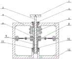
图2为本发明提供的基于同步开关阻尼技术的电磁-压电复合振动控制装置的剖视图;2 is a cross-sectional view of an electromagnetic-piezoelectric composite vibration control device based on synchronous switch damping technology provided by the present invention;
图3为本发明提供的基于同步开关阻尼技术的电磁-压电复合振动控制装置的主视图;3 is a front view of the electromagnetic-piezoelectric composite vibration control device based on the synchronous switch damping technology provided by the present invention;
图4为图3中A-A向的剖视图;Fig. 4 is the sectional view of A-A in Fig. 3;
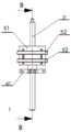
图5为本发明中电磁机构的结构示意图;5 is a schematic structural diagram of an electromagnetic mechanism in the present invention;
图6为图5中B-B向的剖视图;Fig. 6 is the sectional view of B-B among Fig. 5;
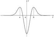
图7为本发明中永磁体相对线圈运动的示意图;7 is a schematic diagram of the movement of the permanent magnet relative to the coil in the present invention;
图8为图7中永磁体运动时线圈的感应电压曲线图;Fig. 8 is a graph of the induced voltage of the coil when the permanent magnet moves in Fig. 7;
图9为本发明中电路系统的原理图;9 is a schematic diagram of a circuit system in the present invention;
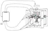
图10为本发明提供的基于同步开关阻尼技术的电磁-压电复合振动控制装置的工作原理图;10 is a working principle diagram of the electromagnetic-piezoelectric composite vibration control device based on the synchronous switch damping technology provided by the present invention;
图11为本发明中电磁电量捕获阶段电路连接图;11 is a circuit connection diagram of the electromagnetic power capture stage in the present invention;
图12为本发明中压电振动控制阶段电路连接图;Fig. 12 is the circuit connection diagram of the piezoelectric vibration control stage in the present invention;
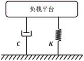
图13为本发明提供的基于同步开关阻尼技术的电磁-压电复合振动控制装置(纯结构)的被动减振原理示意图;13 is a schematic diagram of the passive vibration damping principle of the electromagnetic-piezoelectric composite vibration control device (pure structure) based on the synchronous switch damping technology provided by the present invention;
图14为本发明提供的基于同步开关阻尼技术的电磁-压电复合振动控制装置电磁半主动减振原理示意图;14 is a schematic diagram of the electromagnetic semi-active vibration reduction principle of the electromagnetic-piezoelectric composite vibration control device based on the synchronous switch damping technology provided by the present invention;
图15为本发明提供的基于同步开关阻尼技术的电磁-压电复合振动控制装置电磁-压电复合半主动减振原理示意图;15 is a schematic diagram of the electromagnetic-piezoelectric composite semi-active vibration damping principle of the electromagnetic-piezoelectric composite vibration control device based on the synchronous switch damping technology provided by the present invention;
图16为图13-15中三种情况下的传递率曲线对比图。Fig. 16 is a comparison diagram of the transmissibility curves for the three cases in Figs. 13-15.
附图标记说明:1、负载平台;2、导杆;3、上导向部件;4、上刚性框架;5、电磁机构;51、塑料固定支架;52、线圈;53、永磁体;54、锁紧环;6、上滚轮机构;61、上滚轮支架;7、压电悬臂梁;71、柔性板;72、刚性板;73、压电片;8、下滚轮机构;9、弹性部件;10、垫片;11、下导向部件;12、下刚性框架;13、电路系统;14、压电元件;15、感性元件;16、超级电容;17、调节电阻;18、传感电路;19、第一电子开关;20、第二电子开关。Description of reference numerals: 1. Load platform; 2. Guide rod; 3. Upper guide part; 4. Upper rigid frame; 5. Electromagnetic mechanism; 51. Plastic fixing bracket; 52. Coil; 53. Permanent magnet; Tightening ring; 6. Upper roller mechanism; 61. Upper roller bracket; 7. Piezoelectric cantilever beam; 71. Flexible plate; 72. Rigid plate; 73. Piezoelectric sheet; 8. Lower roller mechanism; 9. Elastic part; 10 , gasket; 11, lower guide part; 12, lower rigid frame; 13, circuit system; 14, piezoelectric element; 15, inductive element; 16, super capacitor; 17, adjusting resistance; 18, sensing circuit; 19, a first electronic switch; 20. a second electronic switch.
具体实施方式Detailed ways
下面将结合本发明实施例中的附图,对本发明实施例中的技术方案进行清楚、完整地描述,显然,所描述的实施例仅仅是本发明一部分实施例,而不是全部的实施例。基于本发明中的实施例,本领域普通技术人员在没有做出创造性劳动前提下所获得的所有其他实施例,都属于本发明保护的范围。The technical solutions in the embodiments of the present invention will be clearly and completely described below with reference to the accompanying drawings in the embodiments of the present invention. Obviously, the described embodiments are only a part of the embodiments of the present invention, but not all of the embodiments. Based on the embodiments of the present invention, all other embodiments obtained by those of ordinary skill in the art without creative efforts shall fall within the protection scope of the present invention.
本发明的目的是提供一种基于同步开关阻尼技术的电磁-压电复合振动控制装置,结构简单,性能可靠,无需外部提供电压源,具有自适应特性。The purpose of the present invention is to provide an electromagnetic-piezoelectric composite vibration control device based on synchronous switch damping technology, which has a simple structure, reliable performance, does not require an external voltage source, and has self-adaptive characteristics.
为使本发明的上述目的、特征和优点能够更加明显易懂,下面结合附图和具体实施方式对本发明作进一步详细的说明。In order to make the above objects, features and advantages of the present invention more clearly understood, the present invention will be described in further detail below with reference to the accompanying drawings and specific embodiments.
如图1-6所示,本实施例提供一种基于同步开关阻尼技术的电磁-压电复合振动控制装置,包括负载平台1、导杆2、上刚性框架4、下刚性框架12、上导向部件3、下导向部件11、上滚轮机构6、下滚轮机构8、弹性部件9、电磁机构5、电路系统13和多个压电悬臂梁7,上刚性框架4设置于下刚性框架12的上部,上导向部件3安装于上刚性框架4中,下导向部件11安装于下刚性部件中,具体地,上导向部件3通过螺钉固定于上刚性框架4上,下导向部件11通过螺钉固定于下刚性框架12上,导杆2套设于上导向部件3和下导向部件11中,导杆2被上导向部件3和下导向部件11约束使其只能作竖直运动,具体地,上导向部件3和下导向部件11均为直线轴承,负载平台1固定于导杆2的上端,具体地,负载平台1与导杆2螺纹连接;上滚轮机构6和下滚轮机构8均固定套设于导杆2上且位于上导向部件3和下导向部件11之间,具体地,上滚轮机构6和下滚轮机构8通过紧定螺钉锁紧于导杆2上,电磁机构5固定套设于导杆2外,弹性部件9套设于下滚轮机构8外,具体地,弹性部件9为复位弹簧,各压电悬臂梁7的一端固定于上刚性框架4和下刚性框架12之间,各压电悬臂梁7的另一端设置于上滚轮机构6和下滚轮机构8之间,从而将压电悬臂梁7约束在竖直方向的单自由度运动上,减少在其他模态上的颤振而损失的能量,压电悬臂梁7和电磁机构5分别与电路系统13连接。As shown in Figures 1-6, this embodiment provides an electromagnetic-piezoelectric composite vibration control device based on synchronous switch damping technology, including a
本实施例中还包括垫片10,垫片10套设于导杆2上,垫片10位于下导向部件11和弹性部件9之间,可以通过调整垫片10使压电悬臂梁7在不同负载的静平衡状态下始终保持于水平平衡位置处。This embodiment also includes a
如图4所示,压电悬臂梁7包括压电片73、柔性板71和刚性板72,柔性板71的一端固定于上刚性框架4和下刚性框架12之间,柔性板71的另一端固定连接有刚性板72,刚性板72设置于上滚轮机构6和下滚轮机构8之间,压电片73贴设于柔性板71上。具体地,上刚性框架4和下刚性框架12通过螺栓连接并将压电悬臂梁7的柔性板71锁紧在其中,压电悬臂梁7的刚性板72与柔性板71通过螺栓连接,刚性板72设置于上滚轮机构6和下滚轮机构8之间,压电片73贴设于柔性板71上。于本具体实施例中,一个压电悬臂梁7包括两个压电片73,两个压电片73分别粘贴于柔性板71的上表面和下表面,且压电片73设置于靠近夹紧端处,且沿柔性板71中性轴对称,具体地,还可根据需求粘结多个压电片73。As shown in FIG. 4 , the
于本具体实施例中,压电悬臂梁7设置为四个,沿导杆2的周向均匀分布,即四个压电悬臂梁7两两对称设置。In this specific embodiment, there are four
上滚轮机构6包括上滚轮支架61、多个上轮轴和多个上滚轮,上滚轮支架61包括上圆筒和多个上支架,上滚轮支架61为一体式结构,上支架、上轮轴、上滚轮和刚性板72为一一对应的关系,上圆筒固定套设于导杆2上,具体地,通过紧定螺钉实现上圆筒的轴向固定,各上支架的一端设置于上圆筒的下部,各上支架的另一端安装有一个上轮轴,各上轮轴上安装有一个上滚轮,一个上滚轮与一个刚性板72的上表面相接触;下滚轮机构8包括下滚轮支架、多个下轮轴和多个下滚轮,下滚轮支架包括下圆筒和多个下支架,下滚轮支架为一体式结构,下支架、下轮轴、下滚轮和刚性板72为一一对应的关系,下圆筒固定套设于导杆2上,具体地,通过紧定螺钉实现下圆筒的轴向固定,各下支架的一端设置于下圆筒的上部,各下支架的另一端安装有一个下轮轴,各下轮轴上安装有一个下滚轮,一个下滚轮与一个刚性板72的下表面相接触。The upper roller mechanism 6 includes an
如图5、6所示,电磁机构5包括塑料固定支架51、锁紧环54、永磁体53和两个线圈52,永磁体53和锁紧环54套设于导杆2上,且锁紧环54、永磁体53和上滚轮支架61由上至下依次设置,永磁体53由锁紧环54锁紧于上滚轮支架61上,塑料固定支架51固定于上刚性框架4上,且塑料固定支架51罩设于永磁体53外部,两个线圈52分别套设于塑料固定支架51外部。通过采用塑料材质的固定支架能够防止铁电材料对永磁体53磁场产生干扰。As shown in FIGS. 5 and 6 , the
塑料固定支架51为圆筒状,塑料固定支架51周向设置有多个竖向滑槽,线圈52套设于塑料固定支架51外,通过在竖向滑槽中设置固定螺栓将线圈52固定于塑料固定支架51上,使得装置在静平衡时,两个线圈52沿永磁体53成对称分布(如图5所示),并通过调整使得分布距离满足恒速运动的永磁体53在平衡位置处时,线圈52产生的感应电压最大。The
如图7、8所示,为上述电磁机构5的配置原理图及对应永磁体53以恒定速度V从上部的线圈52顶端运动至下部的线圈52底端产生的感应电压走势的曲线图。此处采用该配置的原因是,该减振装置在振动的过程中在平衡位置处动能最大,即速度最大,因此,要使得线圈52产生的感应电压尽可能的大,应使恒速运动的永磁体53在平衡位置处也应产生最大的感应电压,而采用单线圈时,在平衡位置处产生的感应电压为零。此外,采用此配置在平衡位置处产生的感应电压近似与系统振动的最大幅值成比例关系,故可为压电的振动控制提供自适应电压源。As shown in FIGS. 7 and 8 , it is a schematic diagram of the configuration of the above-mentioned
如图9所示,为电路系统原理图,多个压电片73并联构成压电元件14,两个线圈52串联构成感性元件15,电路系统13包括调节电阻17,超级电容16,第一电子开关19、第二电子开关20和传感电路18,传感电路18用于检测系统的运动状态从而按需改变第一步电子开关和第二电子开关20的开闭状态,当传感电路18检测到负载平台1到达静平衡位置处时,通过切换第一电子开关19和第二电子开关20的状态使得感性元件15和超级电容16构成回路;当传感电路18检测到负载平台1到达振动峰值处时,通过切换第一电子开关19和第二电子开关20的状态使得压电元件14、调节电阻17、感性元件15和超级电容16依次串联构成闭合回路。As shown in FIG. 9 , which is a schematic diagram of the circuit system, a plurality of
如图9-12所示,结合电路系统原理图对本实施例电磁-压电复合振动控制装置的半主动控制过程作进一步的说明:As shown in Figure 9-12, the semi-active control process of the electromagnetic-piezoelectric composite vibration control device of this embodiment is further described in conjunction with the schematic diagram of the circuit system:
初始,系统电路处于图9所示,第一电子开关19和第二电子开关20全部断开。装置中的负载平台1受外界激励受迫振动,并达到稳定状态。当传感电路18检测到负载平台1到达静平衡位置处时,切换电路中的第一电子开关19和第二电子开关20使其处于图11所示状态,此时只有感性元件15和超级电容16构成回路,便可将此处电磁机构5获得的最大电量存储于超级电容16中,当完成存储时,第一电子开关19和第二电子开关20再次断开至初始状态,完成第一阶段电磁俘能,为下一阶段提供自适应电压源;当传感电路18检测到负载平台1到达振动峰值(极大值和极小值)处时,切换电路中的第一电子开关19和第二电子开关20使其处于图12所示状态,此时压电元件14、调节电阻17、感性元件15和超级电容16依次串联构成闭合回路,由于此时电磁机构5的永磁体53运动速度为零,故感应电压基本为零,此时可将感性元件15视为调节电路的电感元件,故可解决电路系统13需要大电感的问题,而此时超级电容16充当外部电源,完成第二阶段自适应压电同步开关阻尼控制,继而切断第一电子开关19和第二电子开关20完成一个周期的振动控制。由于永磁体53运动方向不同,产生的感应电压正负也不同,可以通过合理配置使得该电压作用于压电元件14时产生的力始终与振动方向相反,从而产生阻尼效应。Initially, the system circuit is as shown in FIG. 9 , and the first
以下对本实施例中的被动减振、电磁半主动减振和电磁-压电复合半主动减振的减振原理进行对比:。The following compares the vibration reduction principles of passive vibration reduction, electromagnetic semi-active vibration reduction, and electromagnetic-piezoelectric composite semi-active vibration reduction in this embodiment: .
如图13所示,本实施例中装置的被动减振是指,电路系统13不工作,完全由机械结构实现减振。其减振机理等效为由系统固有的弹簧-质量-阻尼单元构成的振动系统,其传递率曲线函数G:As shown in FIG. 13 , the passive vibration reduction of the device in this embodiment means that the

式中,x1为负载平台1的振动位移量,x0是激振幅值,C是系统的等效阻尼,K是系统的等效刚度,M是负载平台1的质量,s=jω为拉氏变换的复变量,ω为频域系数。In the formula, x1 is the vibration displacement of the
如图14所示,本实施例中装置的电磁半主动减振是指,只实施系统振动控制第一阶段,即电磁能量捕获,其相当于附加了一个电磁阻尼元件,对应的传递率曲线函数G0:As shown in Figure 14, the electromagnetic semi-active vibration reduction of the device in this embodiment means that only the first stage of system vibration control is implemented, that is, electromagnetic energy capture, which is equivalent to adding an electromagnetic damping element, and the corresponding transmissibility curve function G0 :

式中,x2为本实施例中装置在电磁半主动减振下负载平台1的振动位移量,C0是此情形下系统的等效阻尼,C′为附加的等效电磁阻尼。In the formula, x2 is the vibration displacement of the
如图15所示,为本实施例中装置的电磁-压电复合半主动减振的示意图,其相当于在图14的基础上继而附加了一个压电阻尼元件,其对应的传递率曲线函数G1:As shown in FIG. 15 , a schematic diagram of the electromagnetic-piezoelectric composite semi-active vibration reduction of the device in this embodiment is equivalent to adding a piezoelectric damping element on the basis of FIG. 14 , and its corresponding transmissibility curve functionG1 :

式中,x3为本实施例中装置在电磁-压电复合半主动减振下负载平台1的振动位移量,C1是此情形下系统的等效阻尼,C″为附加的等效压电阻尼。In the formula, x3 is the vibration displacement of the
图16为图13-15中三种情况下的传递率曲线图。从图中实线可以看出系统在被动减振情况下,其传递率曲线在共振峰处有较高的峰值。从图中虚线可以看出,采用电磁半主动控制后,由于电磁阻尼效应,其共振峰值得到了明显的改善。从图中点线可以看出,在采用电磁-压电复合半主动后,由于压电阻尼效应,系统的阻尼得到进一步的增强,从系统的传递率曲线可以看出,系统的共振峰值也进一步得到了改善。Figure 16 is a graph of transmissibility for the three cases in Figures 13-15. It can be seen from the solid line in the figure that in the case of passive vibration reduction, the transmissibility curve of the system has a higher peak value at the resonance peak. It can be seen from the dotted line in the figure that after adopting the electromagnetic semi-active control, the resonance peak value has been significantly improved due to the electromagnetic damping effect. It can be seen from the dotted line in the figure that after the electromagnetic-piezoelectric composite semi-active is adopted, the damping of the system is further enhanced due to the piezoelectric damping effect. It can be seen from the transmissibility curve of the system that the resonance peak value of the system is further enhanced has been improved.
综上可知,本发明提供的基于同步开关阻尼技术的电磁-压电复合振动控制装置,包括电磁机构5、压电悬臂梁7和电路系统13,由于其结构优势,使得电路系统13得到了极大的简化,整个系统可靠性增强,即使电路系统13出现故障,由于电磁机构5及压电悬臂梁7的刚度阻尼特性,也能实现较好的减振效果,结构简单且性能可靠;电磁机构5将电磁感应产生的电量存储于电路系统13中,充当电压源,无需外部提供电压源;电磁机构5产生的感应电压近似与系统的振动最大幅值成比例关系,故其具有自适应电压源特性;由于系统在振动幅值极大时进行切换开关实施压电振动控制,此时电磁机构5的永磁体53速度为零,线圈52感应电压为零,此时可将其作为电路调节的电感元件,电路系统13无需附加大电感。To sum up, the electromagnetic-piezoelectric composite vibration control device based on the synchronous switch damping technology provided by the present invention includes the
本说明书中应用了具体个例对本发明的原理及实施方式进行了阐述,以上实施例的说明只是用于帮助理解本发明的方法及其核心思想;同时,对于本领域的一般技术人员,依据本发明的思想,在具体实施方式及应用范围上均会有改变之处。综上所述,本说明书内容不应理解为对本发明的限制。In this specification, specific examples are used to illustrate the principles and implementations of the present invention, and the descriptions of the above embodiments are only used to help understand the method and the core idea of the present invention; There will be changes in the specific implementation manner and application scope of the idea of the invention. In conclusion, the contents of this specification should not be construed as limiting the present invention.
Claims (8)
Priority Applications (2)
| Application Number | Priority Date | Filing Date | Title |
|---|---|---|---|
| CN201910898079.7ACN110578770B (en) | 2019-09-23 | 2019-09-23 | Electromagnetic-piezoelectric composite vibration control device based on synchronous switch damping technology |
| US16/683,478US11489104B2 (en) | 2019-09-23 | 2019-11-14 | Electromagnetic-piezoelectric composite vibration control device based on synchronized switch damping technology |
Applications Claiming Priority (1)
| Application Number | Priority Date | Filing Date | Title |
|---|---|---|---|
| CN201910898079.7ACN110578770B (en) | 2019-09-23 | 2019-09-23 | Electromagnetic-piezoelectric composite vibration control device based on synchronous switch damping technology |
Publications (2)
| Publication Number | Publication Date |
|---|---|
| CN110578770A CN110578770A (en) | 2019-12-17 |
| CN110578770Btrue CN110578770B (en) | 2020-07-28 |
Family
ID=68813297
Family Applications (1)
| Application Number | Title | Priority Date | Filing Date |
|---|---|---|---|
| CN201910898079.7AActiveCN110578770B (en) | 2019-09-23 | 2019-09-23 | Electromagnetic-piezoelectric composite vibration control device based on synchronous switch damping technology |
Country Status (2)
| Country | Link |
|---|---|
| US (1) | US11489104B2 (en) |
| CN (1) | CN110578770B (en) |
Families Citing this family (7)
| Publication number | Priority date | Publication date | Assignee | Title |
|---|---|---|---|---|
| JP2020045929A (en)* | 2018-09-14 | 2020-03-26 | 三菱重工業株式会社 | Vibration damping device and electric actuator |
| CN110544976B (en)* | 2019-09-23 | 2021-02-02 | 重庆大学 | Piezoelectric self-powered composite beam vibration damping device and control method thereof |
| US11998948B2 (en)* | 2020-07-06 | 2024-06-04 | Cirrus Logic Inc. | Driver circuitry for piezoelectric transducers |
| CN113394941B (en)* | 2021-06-16 | 2022-11-11 | 西北工业大学 | An electromagnetic-piezoelectric hybrid dual-effect quasi-zero stiffness vibration energy harvesting device |
| CN115313595B (en)* | 2022-06-30 | 2025-08-29 | 哈尔滨工业大学(深圳) | A highly efficient new energy vibration controller integrating passive, semi-active and active control |
| CN116398566B (en)* | 2023-05-16 | 2025-09-16 | 大连地拓精密科技股份有限公司 | Ultralow-frequency double-degree-of-freedom active and passive micro-vibration prevention device based on magnetic levitation |
| CN120044692B (en)* | 2025-04-27 | 2025-07-08 | 北京航宇振控科技有限责任公司 | A new type of fast mirror based on piezoelectric and electromagnetic composite drive |
Family Cites Families (10)
| Publication number | Priority date | Publication date | Assignee | Title |
|---|---|---|---|---|
| JPS59103043A (en)* | 1982-12-02 | 1984-06-14 | Nissan Motor Co Ltd | Power unit mounting device |
| US7642741B2 (en)* | 2005-04-27 | 2010-01-05 | Sidman Adam D | Handheld platform stabilization system employing distributed rotation sensors |
| US20130201316A1 (en)* | 2012-01-09 | 2013-08-08 | May Patents Ltd. | System and method for server based control |
| CN204258662U (en)* | 2014-10-28 | 2015-04-08 | 扬州大学 | Piling machine formula piezoelectric generating device |
| US20180233856A1 (en)* | 2015-05-22 | 2018-08-16 | Rnd By Us B.V. | Holding device |
| CN105141181B (en)* | 2015-10-08 | 2018-02-02 | 北京理工大学 | A kind of piezoelectricity electromagnetism combined type energy accumulator |
| CN108716521B (en)* | 2018-06-01 | 2020-08-25 | 中国人民解放军海军工程大学 | Vibration energy collecting device based on nonlinear energy trap |
| CN109000114B (en)* | 2018-08-16 | 2020-02-18 | 上海交通大学 | Self-feedback tri-stable variable stiffness micro-vibration isolation device based on PVC Gel |
| CN110190778B (en)* | 2019-06-05 | 2020-09-15 | 北京市劳动保护科学研究所 | A low frequency vibration isolation and piezoelectric energy capture coupling device |
| CN110219921B (en)* | 2019-07-09 | 2024-03-08 | 海南大学 | A semi-active, quasi-zero stiffness adjustable vibration isolator |
- 2019
- 2019-09-23CNCN201910898079.7Apatent/CN110578770B/enactiveActive
- 2019-11-14USUS16/683,478patent/US11489104B2/enactiveActive
Also Published As
| Publication number | Publication date |
|---|---|
| CN110578770A (en) | 2019-12-17 |
| US11489104B2 (en) | 2022-11-01 |
| US20210091296A1 (en) | 2021-03-25 |
Similar Documents
| Publication | Publication Date | Title |
|---|---|---|
| CN110578770B (en) | Electromagnetic-piezoelectric composite vibration control device based on synchronous switch damping technology | |
| US8803644B2 (en) | Magnetic actuator | |
| CN110645310B (en) | Piezoelectric self-powered electromagnetic negative stiffness vibration isolation system and control method thereof | |
| CN108708927B (en) | A Variable Stiffness Vibration Isolator Based on Multilayer Dielectric Elastomer Film | |
| CN107339352B (en) | An electromagnetic electromechanical coupling circuit tuned vibration absorber | |
| CN104806693B (en) | Intelligent Adaptive Vibration Absorber, Array Integration Device and Its Application | |
| Yan et al. | Enhanced lever-type vibration isolator via electromagnetic shunt damping | |
| CN105207524A (en) | Semi-active frequency modulation vibration energy capturer | |
| CN107654552B (en) | A Quasi-Zero Stiffness Vibration Isolator Using Piezoelectric Sheets for Neutral Adjustment | |
| CN110544976A (en) | Piezoelectric self-powered composite beam vibration damping device and its control method | |
| CN110513419A (en) | An adjustable zero-stiffness vibration isolator based on magnetic circuit design | |
| WO2014023057A1 (en) | Magnetic mechanism with negative rigidity | |
| CN117450201A (en) | Excitation frequency self-adaptive vibration isolator | |
| CN105927694B (en) | A kind of adjustable negative rigidity mechanism based on time-dependent current magnetic field | |
| CN109630581A (en) | For using the system of inductor and tuning Magnetic buffer in the isolation of magnetic skyhook damping device | |
| CN111981085A (en) | Elastic-hysteretic low-frequency large-displacement vibration isolator based on electromagnetic negative stiffness | |
| CN105673769B (en) | Using the active-passive integratedization vibration isolator and vibration isolating method of composite dielectric elastomeric material | |
| CN105840727B (en) | A kind of adjustable rigidity mechanism of axial magnetic coupling | |
| CN111779790B (en) | a vibration damping device | |
| CN111810582A (en) | An electromagnetic coupling tunable two-degree-of-freedom dynamic vibration absorber | |
| JP4421130B2 (en) | Vibration isolation method and apparatus | |
| CN110513422A (en) | A New Lever Type Nonlinear Eddy Current Damper | |
| CN108054896B (en) | A three-degree-of-freedom electromagnetic vibration absorption and energy harvester | |
| CN108019452B (en) | A kind of half actively controllable linear Stiffness electromagnetism vibration isolator | |
| CN106090098B (en) | Variation rigidity variable damping is tunable dynamic vibration absorber |
Legal Events
| Date | Code | Title | Description |
|---|---|---|---|
| PB01 | Publication | ||
| PB01 | Publication | ||
| SE01 | Entry into force of request for substantive examination | ||
| SE01 | Entry into force of request for substantive examination | ||
| GR01 | Patent grant | ||
| GR01 | Patent grant |