CN110578733B - A hydraulic cylinder with built-in energy storage in the piston rod - Google Patents
A hydraulic cylinder with built-in energy storage in the piston rodDownload PDFInfo
- Publication number
- CN110578733B CN110578733BCN201910850146.8ACN201910850146ACN110578733BCN 110578733 BCN110578733 BCN 110578733BCN 201910850146 ACN201910850146 ACN 201910850146ACN 110578733 BCN110578733 BCN 110578733B
- Authority
- CN
- China
- Prior art keywords
- hydraulic cylinder
- cylinder
- hydraulic
- outlet
- piston
- Prior art date
- Legal status (The legal status is an assumption and is not a legal conclusion. Google has not performed a legal analysis and makes no representation as to the accuracy of the status listed.)
- Active
Links
- 238000004146energy storageMethods0.000titleclaimsabstractdescription19
- 239000010720hydraulic oilSubstances0.000claimsabstractdescription9
- 239000010727cylinder oilSubstances0.000claimsdescription18
- 239000003921oilSubstances0.000claimsdescription18
- 238000007789sealingMethods0.000claimsdescription10
- 238000011084recoveryMethods0.000claimsdescription2
- 230000006835compressionEffects0.000claims1
- 238000007906compressionMethods0.000claims1
- 239000012530fluidSubstances0.000claims1
- 230000005540biological transmissionEffects0.000abstractdescription5
- 230000008929regenerationEffects0.000description6
- 238000011069regeneration methodMethods0.000description6
- 239000007788liquidSubstances0.000description2
- 238000005516engineering processMethods0.000description1
- 238000009434installationMethods0.000description1
- 238000000034methodMethods0.000description1
- 238000005381potential energyMethods0.000description1
- 239000000725suspensionSubstances0.000description1
Images


Classifications
- F—MECHANICAL ENGINEERING; LIGHTING; HEATING; WEAPONS; BLASTING
- F15—FLUID-PRESSURE ACTUATORS; HYDRAULICS OR PNEUMATICS IN GENERAL
- F15B—SYSTEMS ACTING BY MEANS OF FLUIDS IN GENERAL; FLUID-PRESSURE ACTUATORS, e.g. SERVOMOTORS; DETAILS OF FLUID-PRESSURE SYSTEMS, NOT OTHERWISE PROVIDED FOR
- F15B15/00—Fluid-actuated devices for displacing a member from one position to another; Gearing associated therewith
- F15B15/08—Characterised by the construction of the motor unit
- F15B15/14—Characterised by the construction of the motor unit of the straight-cylinder type
- F15B15/1423—Component parts; Constructional details
- F15B15/1438—Cylinder to end cap assemblies
- F15B15/1442—End cap sealings
- F—MECHANICAL ENGINEERING; LIGHTING; HEATING; WEAPONS; BLASTING
- F15—FLUID-PRESSURE ACTUATORS; HYDRAULICS OR PNEUMATICS IN GENERAL
- F15B—SYSTEMS ACTING BY MEANS OF FLUIDS IN GENERAL; FLUID-PRESSURE ACTUATORS, e.g. SERVOMOTORS; DETAILS OF FLUID-PRESSURE SYSTEMS, NOT OTHERWISE PROVIDED FOR
- F15B15/00—Fluid-actuated devices for displacing a member from one position to another; Gearing associated therewith
- F15B15/08—Characterised by the construction of the motor unit
- F15B15/14—Characterised by the construction of the motor unit of the straight-cylinder type
- F15B15/1423—Component parts; Constructional details
- F15B15/1457—Piston rods
- F—MECHANICAL ENGINEERING; LIGHTING; HEATING; WEAPONS; BLASTING
- F15—FLUID-PRESSURE ACTUATORS; HYDRAULICS OR PNEUMATICS IN GENERAL
- F15B—SYSTEMS ACTING BY MEANS OF FLUIDS IN GENERAL; FLUID-PRESSURE ACTUATORS, e.g. SERVOMOTORS; DETAILS OF FLUID-PRESSURE SYSTEMS, NOT OTHERWISE PROVIDED FOR
- F15B21/00—Common features of fluid actuator systems; Fluid-pressure actuator systems or details thereof, not covered by any other group of this subclass
- F15B21/14—Energy-recuperation means
Landscapes
- Engineering & Computer Science (AREA)
- Physics & Mathematics (AREA)
- Fluid Mechanics (AREA)
- Mechanical Engineering (AREA)
- General Engineering & Computer Science (AREA)
- Chemical & Material Sciences (AREA)
- Analytical Chemistry (AREA)
- Actuator (AREA)
Abstract
Translated fromChinese
Description
Translated fromChinese技术领域technical field
本发明涉及一种活塞杆内置储能型液压缸,特别是涉及可实现工程装备的液压势能再生、车辆主动式液压悬架能量再生的活塞杆内置储能型液压缸。The invention relates to a hydraulic cylinder with built-in energy storage in a piston rod, in particular to a hydraulic cylinder with built-in energy storage in a piston rod, which can realize the regeneration of hydraulic potential energy of engineering equipment and the energy of active hydraulic suspension of vehicles.
背景技术Background technique
液压缸是一种液压传动系统中的直线型执行元件,主要包括:活塞、活塞杆、缸筒、缸盖等零件。Hydraulic cylinder is a linear actuator in the hydraulic transmission system, mainly including: piston, piston rod, cylinder barrel, cylinder head and other parts.
近年来,液压传动系统的能量再生技术得到广泛应用,尤其是液压缸和蓄能器组合成为能量再生系统的核心部分。但是,液压缸和蓄能器都是液压传动系统的独立部件,能量再生系统设计必须要考虑两者之间的控制阀、管路、安装等问题,导致能量再生系统十分复杂、体积庞大,不能完全适应工程应用的实际要求。因此,如果能够在液压缸内部直接设置蓄能模块,将可再生能量直接存储于蓄能模块中,不仅减少了控制阀和管路等环节能量损失,也大幅降低了再生系统的复杂程度和体积,并可直接应用于各类液压驱动的工程应用,提高液压传动系统的能量效率。In recent years, the energy regeneration technology of hydraulic transmission system has been widely used, especially the combination of hydraulic cylinder and accumulator has become the core part of the energy regeneration system. However, both the hydraulic cylinder and the accumulator are independent components of the hydraulic transmission system, and the design of the energy regeneration system must consider the control valve, pipeline, installation and other issues between the two, resulting in a very complex and bulky energy regeneration system, which cannot be Fully adapt to the actual requirements of engineering applications. Therefore, if the energy storage module can be directly installed inside the hydraulic cylinder, the renewable energy can be directly stored in the energy storage module, which not only reduces the energy loss of the control valve and pipeline, but also greatly reduces the complexity and volume of the regeneration system. , and can be directly applied to various hydraulic drive engineering applications to improve the energy efficiency of the hydraulic transmission system.
发明内容SUMMARY OF THE INVENTION
本发明的目的在于提供一种活塞内置储能型液压缸结构,其特征在于:包括液压缸体、储能单元、液压缸工作单元;所述储能单元包括液压缸油液进/出口、控制阀活塞、弹簧档板、气缸油液进/出口、控制阀、气缸活塞、控制阀油液进/出口和气缸气体进/出口;所述液压缸工作单元包括液压缸无杆腔进/出油口、活塞固定螺母、液压缸活塞、缓冲套、液压缸有杆腔进/出油口、液压缸密封端盖、端盖固定螺钉和液压缸活塞杆,液压缸活塞杆内部设置了一个气缸腔,气缸腔内放置一个气缸活塞,气缸活塞可在气缸腔内运动,气缸腔与液压缸无杆腔之间设置了一个控制阀;液压缸体液压缸腔内,液压缸活塞通过活塞固定螺母安装在油缸活塞杆一端上,且液压缸活塞和液压缸活塞杆之间设置了一个缓冲套,其中液压缸活塞可在液压缸腔内平滑运动;液压缸活塞杆另一端穿过一个液压缸密封端盖,利用端盖固定螺钉安装在液压缸体上,且液压缸活塞杆可在液压缸密封端盖中平滑运动。The purpose of the present invention is to provide a piston built-in energy storage type hydraulic cylinder structure, which is characterized in that it includes a hydraulic cylinder block, an energy storage unit, and a hydraulic cylinder working unit; the energy storage unit includes a hydraulic cylinder oil inlet/outlet, a control Valve piston, spring baffle, cylinder oil inlet/outlet, control valve, cylinder piston, control valve oil inlet/outlet and cylinder gas inlet/outlet; the hydraulic cylinder working unit includes the hydraulic cylinder rodless cavity inlet/outlet Port, piston fixing nut, hydraulic cylinder piston, buffer sleeve, hydraulic cylinder rod cavity inlet/outlet port, hydraulic cylinder sealing end cover, end cover fixing screw and hydraulic cylinder piston rod, a cylinder cavity is set inside the hydraulic cylinder piston rod , a cylinder piston is placed in the cylinder cavity, the cylinder piston can move in the cylinder cavity, a control valve is set between the cylinder cavity and the rodless cavity of the hydraulic cylinder; in the hydraulic cylinder cavity of the hydraulic cylinder block, the hydraulic cylinder piston is installed through the piston fixing nut A buffer sleeve is arranged on one end of the piston rod of the hydraulic cylinder and between the piston of the hydraulic cylinder and the piston rod of the hydraulic cylinder, wherein the piston of the hydraulic cylinder can move smoothly in the hydraulic cylinder cavity; the other end of the piston rod of the hydraulic cylinder passes through a sealing end of the hydraulic cylinder The cover is mounted on the hydraulic cylinder body with the end cover fixing screws, and the hydraulic cylinder piston rod can move smoothly in the sealing end cover of the hydraulic cylinder.
本发明其他方面、目的和优点结合附图对其进行描述将变得更加明显。Other aspects, objects and advantages of the present invention will become more apparent from the description of the accompanying drawings.
附图说明Description of drawings
结合说明书里的并形成说明书一部分的附图显示了本发明的若干方面,并且附图与下面的描述一起来阐述本发明的工作原理。在附图中:The accompanying drawings, which are incorporated in and form a part of the specification, illustrate several aspects of the invention and, together with the following description, serve to explain the principles of operation of the invention. In the attached image:
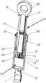
图1是活塞杆内置储能型液压缸的立体剖视图;Figure 1 is a perspective cross-sectional view of a piston rod built-in energy storage hydraulic cylinder;
图2是活塞杆内置储能型液压缸的剖视图;Figure 2 is a cross-sectional view of a piston rod built-in energy storage hydraulic cylinder;
图3是活塞杆内置储能型液压缸中控制阀剖视图。Fig. 3 is a sectional view of a control valve in a hydraulic cylinder with built-in energy storage in a piston rod.
在上述附图中:1、液压缸体, 10、储能单元,11、液压缸油液进/出口,12、控制阀活塞,13、弹簧档板,14、气缸油液进/出口,15、控制阀,16、气缸活塞,17、控制阀油液进/出口,18、气缸气体进/出口,20、液压缸工作单元,21、液压缸无杆腔进/出油口,22、活塞固定螺母,23、液压缸活塞,24、缓冲套,25、液压缸有杆腔进/出油口,26、油缸密封端盖,27、端盖固定螺钉,28、液压缸活塞杆。In the above drawings: 1, hydraulic cylinder block, 10, energy storage unit, 11, hydraulic cylinder oil inlet/outlet, 12, control valve piston, 13, spring baffle, 14, cylinder oil inlet/outlet, 15 , Control valve, 16, Cylinder piston, 17, Control valve oil inlet/outlet, 18, Cylinder gas inlet/outlet, 20, Hydraulic cylinder working unit, 21, Hydraulic cylinder rodless cavity inlet/outlet, 22, Piston Fixing nut, 23, hydraulic cylinder piston, 24, buffer sleeve, 25, hydraulic cylinder with rod cavity inlet/outlet port, 26, cylinder sealing end cap, 27, end cap fixing screw, 28, hydraulic cylinder piston rod.
具体实施方式Detailed ways
以下将结合附图和具体实施方式对本发明做一个详细的说明。The present invention will be described in detail below with reference to the accompanying drawings and specific embodiments.
本发明提供一种活塞杆内置储能型液压缸,参见图1,一种活塞杆内置储能型液压缸,其特征在于:包括液压缸体1、储能单元10、液压缸工作单元20。The present invention provides a hydraulic cylinder with built-in energy storage in a piston rod, referring to FIG.
参见图2-图3,储能单元10包括液压缸油液进/出口11、控制阀活塞12、弹簧档板13、气缸油液进/出口14、控制阀15、气缸活塞16、控制阀油液进/出口17和气缸气体进/出口18。2-3, the
液压缸工作单元20包括液压缸无杆腔进/出油口21、活塞固定螺母22、液压缸活塞23、缓冲套24、液压缸有杆腔进/出油口25、液压缸密封端盖26、端盖固定螺钉27和液压缸活塞杆28。The hydraulic
液压缸活塞杆28内部设置了一个气缸腔,气缸腔内放置一个气缸活塞16,气缸活塞16可在气缸腔内运动,气缸腔与液压缸无杆腔之间设置了一个控制阀15,油缸体1油缸腔内,液压缸活塞23通过活塞固定螺母22安装在液压缸活塞杆28一端上,且液压缸活塞23和液压缸活塞杆28之间设置了一个缓冲套24,其中液压缸活塞23可在液压缸腔内平滑运动,液压缸活塞杆28另一端穿过一个油缸密封端盖26,利用端盖固定螺钉27安装在液压缸体1上,且液压缸活塞杆28可在液压缸密封端盖26中平滑运动。A cylinder cavity is arranged inside the
液压缸活塞杆28内部具有一个气缸腔。气缸腔和液压缸无杆腔之间,通过一个控制阀15实现油液流向控制,控制阀15具有控制阀活塞12、弹簧档板13和三个进/出油口,三个进/出油口分别为气缸油液进/出口14、控制阀油液进/出口17和液压缸油液进/出口11。The hydraulic
本发明的具体工作原理如下:The concrete working principle of the present invention is as follows:
当工作结束时,液压缸活塞杆28回缩时,液压缸活塞23在液压缸腔内向下运动时,压缩液压缸无杆腔内液压油,此时,液压缸无杆腔内的高压液压油可通过在液压缸活塞杆28底部的控制阀15上的液压缸油液进/出口11进入,高压油则推动控制阀中的弹簧档板13压缩,从而使得具有压力的液压油可以从气缸油液进/出口14中进入气缸活塞16一端的气缸腔内,推动气缸活塞16在气缸腔内运动,压缩气缸活塞16另一端气缸腔内的气体,当气体压缩到一定量后,弹簧档板13回位将入口关闭,达到能量回收的目的。When the work is over, when the hydraulic
当需要工作时,可向控制阀15上的控制阀油液进/出口17通入一个低压的液压油,使其推动控制阀15中的控制阀活塞12运动,从而使得弹簧档板13压缩,此时,之前已压缩好的气体释放,推动气缸活塞16使得油液通过气缸油液进/出口14从液压缸油液进/出口11进入液压缸无杆腔内,辅助主油路共同推动液压缸活塞23运动,使液压缸活塞杆28向外伸,实现能量再利用。When it needs to work, a low-pressure hydraulic oil can be introduced into the control valve oil inlet/
Claims (1)
Translated fromChinesePriority Applications (1)
| Application Number | Priority Date | Filing Date | Title |
|---|---|---|---|
| CN201910850146.8ACN110578733B (en) | 2019-09-10 | 2019-09-10 | A hydraulic cylinder with built-in energy storage in the piston rod |
Applications Claiming Priority (1)
| Application Number | Priority Date | Filing Date | Title |
|---|---|---|---|
| CN201910850146.8ACN110578733B (en) | 2019-09-10 | 2019-09-10 | A hydraulic cylinder with built-in energy storage in the piston rod |
Publications (2)
| Publication Number | Publication Date |
|---|---|
| CN110578733A CN110578733A (en) | 2019-12-17 |
| CN110578733Btrue CN110578733B (en) | 2020-11-27 |
Family
ID=68812841
Family Applications (1)
| Application Number | Title | Priority Date | Filing Date |
|---|---|---|---|
| CN201910850146.8AActiveCN110578733B (en) | 2019-09-10 | 2019-09-10 | A hydraulic cylinder with built-in energy storage in the piston rod |
Country Status (1)
| Country | Link |
|---|---|
| CN (1) | CN110578733B (en) |
Families Citing this family (2)
| Publication number | Priority date | Publication date | Assignee | Title |
|---|---|---|---|---|
| CN116696887A (en)* | 2023-06-25 | 2023-09-05 | 山东临工工程机械有限公司 | Novel cylinder-in-cylinder flow renewable hydraulic cylinder |
| CN117536946B (en)* | 2023-12-29 | 2024-04-30 | 浙江路得坦摩汽车部件股份有限公司 | Damping linear change oil hydraulic cylinder with buffering function |
Citations (8)
| Publication number | Priority date | Publication date | Assignee | Title |
|---|---|---|---|---|
| JPS4947226B1 (en)* | 1969-03-25 | 1974-12-14 | ||
| WO1999034119A1 (en)* | 1997-12-23 | 1999-07-08 | Anders Sten Wedell | Hydraulic unit |
| WO2008012704A2 (en)* | 2006-07-28 | 2008-01-31 | Ercio Miguel Nema | Hydropneumatic regenerative actuator |
| CN101312866A (en)* | 2005-10-06 | 2008-11-26 | 克诺尔商用车制动系统有限公司 | Combined service brake and spring-loaded brake cylinder with an inner ventilation |
| CN103470568A (en)* | 2013-09-25 | 2013-12-25 | 浙江美科斯叉车有限公司 | Oil cylinder without oil return port |
| CN105757050A (en)* | 2016-05-01 | 2016-07-13 | 张述成 | Energy storage type valve cylinder structure with buffer brake function |
| CN205592217U (en)* | 2016-03-22 | 2016-09-21 | 衢州市辰泰机械制造有限公司 | Air energy storage load cylinder structure |
| CN109268322A (en)* | 2018-11-13 | 2019-01-25 | 湖南特力液压有限公司 | Energy-storage hydraulic device |
- 2019
- 2019-09-10CNCN201910850146.8Apatent/CN110578733B/enactiveActive
Patent Citations (8)
| Publication number | Priority date | Publication date | Assignee | Title |
|---|---|---|---|---|
| JPS4947226B1 (en)* | 1969-03-25 | 1974-12-14 | ||
| WO1999034119A1 (en)* | 1997-12-23 | 1999-07-08 | Anders Sten Wedell | Hydraulic unit |
| CN101312866A (en)* | 2005-10-06 | 2008-11-26 | 克诺尔商用车制动系统有限公司 | Combined service brake and spring-loaded brake cylinder with an inner ventilation |
| WO2008012704A2 (en)* | 2006-07-28 | 2008-01-31 | Ercio Miguel Nema | Hydropneumatic regenerative actuator |
| CN103470568A (en)* | 2013-09-25 | 2013-12-25 | 浙江美科斯叉车有限公司 | Oil cylinder without oil return port |
| CN205592217U (en)* | 2016-03-22 | 2016-09-21 | 衢州市辰泰机械制造有限公司 | Air energy storage load cylinder structure |
| CN105757050A (en)* | 2016-05-01 | 2016-07-13 | 张述成 | Energy storage type valve cylinder structure with buffer brake function |
| CN109268322A (en)* | 2018-11-13 | 2019-01-25 | 湖南特力液压有限公司 | Energy-storage hydraulic device |
Also Published As
| Publication number | Publication date |
|---|---|
| CN110578733A (en) | 2019-12-17 |
Similar Documents
| Publication | Publication Date | Title |
|---|---|---|
| CN110578733B (en) | A hydraulic cylinder with built-in energy storage in the piston rod | |
| CN104930017B (en) | Hydraulic device capable of adjusting buffer energy on two ends | |
| CN106979181B (en) | High-energy-efficiency hydraulic servo oil cylinder with bidirectional buffering and precise force control functions | |
| CN107816505A (en) | A kind of active control hydraulic servo buffer | |
| CN112431800B (en) | Gas-liquid isolation sealing method for piston accumulator | |
| CN103016597B (en) | Self-powered damper based on vibration energy recovery | |
| CN110630582B (en) | Cylinder energy storage type hydraulic cylinder | |
| CN107588150A (en) | Especially big load hydraulic bjuffer | |
| CN108266413B (en) | Asymmetric electro-hydrostatic actuator based on pressure selection valve | |
| CN105782137B (en) | A kind of super-pressure accumulator | |
| CN211449233U (en) | Accumulator assembly for double-hydraulic-cylinder hydraulic system | |
| CN110578732A (en) | A welded piston rod built-in energy storage hydraulic cylinder | |
| CN206290519U (en) | Retractable actuating cylinder hydraulic circuit components | |
| CN104074812B (en) | A kind of hydraulic booster energy-recuperation system and control device | |
| CN206708114U (en) | Energy-efficient hydraulic servo cylinders with bi-directional cushioning and precise force control | |
| CN108547826A (en) | A kind of built-in gas-liquid mixed buffering stretching type high-speed cylinder | |
| CN110594236B (en) | A hydraulic cylinder with energy storage at the bottom of the cylinder | |
| CN207762048U (en) | A kind of double acting hydraulic cylinder of built-in accumulator | |
| CN203453173U (en) | Beading pushing oil cylinder of steel rail flash welding machine | |
| CN115199610A (en) | A full-stroke self-locking mechanism of a hydraulic cylinder | |
| CN205533543U (en) | Hydro -cylinder with integrated hydraulic pressure lock cylinder end | |
| CN113323941B (en) | Buffer device of oil cylinder and oil cylinder | |
| CN208185132U (en) | A kind of self-locking oil cylinder | |
| CN115949643B (en) | A pollution isolation device for helicopter hydraulic system | |
| CN112065806A (en) | Hydraulic cylinder unloading structure |
Legal Events
| Date | Code | Title | Description |
|---|---|---|---|
| PB01 | Publication | ||
| PB01 | Publication | ||
| SE01 | Entry into force of request for substantive examination | ||
| SE01 | Entry into force of request for substantive examination | ||
| GR01 | Patent grant | ||
| GR01 | Patent grant |