CN110576405B - A screw gun for assembly - Google Patents
A screw gun for assemblyDownload PDFInfo
- Publication number
- CN110576405B CN110576405BCN201910753058.6ACN201910753058ACN110576405BCN 110576405 BCN110576405 BCN 110576405BCN 201910753058 ACN201910753058 ACN 201910753058ACN 110576405 BCN110576405 BCN 110576405B
- Authority
- CN
- China
- Prior art keywords
- sliding
- cylinder
- spring
- rod
- handle
- Prior art date
- Legal status (The legal status is an assumption and is not a legal conclusion. Google has not performed a legal analysis and makes no representation as to the accuracy of the status listed.)
- Active
Links
Images


Classifications
- B—PERFORMING OPERATIONS; TRANSPORTING
- B25—HAND TOOLS; PORTABLE POWER-DRIVEN TOOLS; MANIPULATORS
- B25B—TOOLS OR BENCH DEVICES NOT OTHERWISE PROVIDED FOR, FOR FASTENING, CONNECTING, DISENGAGING OR HOLDING
- B25B21/00—Portable power-driven screw or nut setting or loosening tools; Attachments for drilling apparatus serving the same purpose
- B—PERFORMING OPERATIONS; TRANSPORTING
- B25—HAND TOOLS; PORTABLE POWER-DRIVEN TOOLS; MANIPULATORS
- B25B—TOOLS OR BENCH DEVICES NOT OTHERWISE PROVIDED FOR, FOR FASTENING, CONNECTING, DISENGAGING OR HOLDING
- B25B23/00—Details of, or accessories for, spanners, wrenches, screwdrivers
- B25B23/02—Arrangements for handling screws or nuts
- B25B23/04—Arrangements for handling screws or nuts for feeding screws or nuts
Landscapes
- Engineering & Computer Science (AREA)
- Mechanical Engineering (AREA)
- Details Of Spanners, Wrenches, And Screw Drivers And Accessories (AREA)
Abstract
Translated fromChinese
Description
Translated fromChinese技术领域technical field
本发明涉及一种螺丝钉枪,尤其涉及一种装配用螺丝钉枪。The invention relates to a screw gun, in particular to a screw gun for assembly.
背景技术Background technique
螺钉常见于机械、电器及建筑物等,螺钉不需要螺母,可以直接与两个物体相配合,工具一般用批头,头部多为一字槽,十字槽,内外六角也很多,一般较小。Screws are commonly found in machinery, electrical appliances and buildings. Screws do not require nuts and can be directly matched with two objects. Tools generally use batch heads. .
现在使用螺钉将两个物体进行固定时,需要操作者一只手握螺钉,另一只手使用相对应的螺丝刀将螺钉固定在需要配合的位置,如此操作需要操作者通过手眼配合使螺丝刀与螺钉对齐,还有一种是操作者先将螺钉放置在需要固定的位置,再使用带有批头的电钻将螺钉固定在需要配合的位置,这两种方式的操作过程都过于复杂,而且操作者无法随身携带大量的螺钉。Now, when using screws to fix two objects, the operator needs to hold the screw in one hand, and the other hand uses the corresponding screwdriver to fix the screw in the position that needs to be matched. This operation requires the operator to match the screwdriver with the screw through hand-eye coordination. Alignment, another is that the operator first places the screw in the position that needs to be fixed, and then uses an electric drill with a bit to fix the screw in the position that needs to be matched. The operation process of these two methods is too complicated, and the operator cannot. Carry a lot of screws with you.
因此,发明一种可简单快速的将批头与螺钉对齐,且能够容纳大量的螺钉,使用方便,且安全系数高的装配用螺丝钉枪来解决以上问题来说很有必要。Therefore, it is necessary to invent a screw gun for assembly that can easily and quickly align the bits with the screws, can accommodate a large number of screws, is easy to use, and has a high safety factor to solve the above problems.
发明内容SUMMARY OF THE INVENTION
为了克服需要操作者通过手眼配合使螺丝刀与螺钉对齐,无法携带大量螺钉的缺点,要解决的技术问题为:提供一种可简单快速的将批头与螺钉对齐,且能够容纳大量的螺钉,使用方便,且安全系数高的装配用螺丝钉枪。In order to overcome the disadvantage that the operator needs to align the screwdriver with the screw through hand-eye coordination, and cannot carry a large number of screws, the technical problem to be solved is to provide a method that can simply and quickly align the bit with the screw, and can accommodate a large number of screws. A convenient and high safety screw gun for assembly.
本发明的技术方案是:一种装配用螺丝钉枪,包括有空心把手和减速电机,空心把手底部左侧安装有减速电机,还包括有滑动部件、轴承座、批头、驱动装置和弧形板,减速电机底部设有滑动部件,滑动部件上部安装有轴承座,滑动部件底部安装有批头,其中所述滑动部件用于带动批头移动,空心把手下方设有驱动装置,驱动装置的连接件与轴承座连接,其中所述驱动装置用于驱动滑动部件与批头向下滑动,空心把手右侧铰接连接有弧形板,弧形板与空心把手配合。The technical scheme of the present invention is as follows: a screw gun for assembling, comprising a hollow handle and a deceleration motor, a deceleration motor is installed on the left side of the bottom of the hollow handle, and also includes a sliding part, a bearing seat, a batch head, a driving device and an arc-shaped plate , the bottom of the geared motor is provided with a sliding part, the upper part of the sliding part is installed with a bearing seat, and the bottom of the sliding part is installed with a bit head, wherein the sliding part is used to drive the bit head to move, a driving device is arranged under the hollow handle, and the connecting piece of the driving device It is connected with the bearing seat, wherein the driving device is used to drive the sliding part and the bit to slide down, and the right side of the hollow handle is hingedly connected with an arc-shaped plate, and the arc-shaped plate is matched with the hollow handle.
进一步的,滑动部件包括有六棱杆、六棱孔套和第一弹簧,减速电机的输出轴上安装有六棱杆,六棱杆上滑动式设有六棱孔套,轴承座安装在六棱孔套的上部,六棱杆底端与六棱孔套内底部之间连接有第一弹簧,六棱孔套底部与批头顶端连接。Further, the sliding part includes a hexagonal rod, a hexagonal hole sleeve and a first spring, a hexagonal rod is installed on the output shaft of the reduction motor, and a hexagonal hole sleeve is slidably provided on the hexagonal rod, and the bearing seat is installed on the hexagonal rod. A first spring is connected between the bottom end of the hexagonal rod and the inner bottom of the hexagonal hole sleeve on the upper part of the rib hole sleeve, and the bottom of the hexagonal hole sleeve is connected with the top of the batch head.
进一步的,驱动装置包括有握把、储液框、连接杆、第一活塞、第二弹簧、出液管、缸体、第二活塞和L型杆,空心把手下方铰接连接有握把,空心把手底部右侧安装有储液框,握把顶部右侧安装有连接杆,连接杆上部位于储液框内,储液框内滑动式设有第一活塞,连接杆顶端与第一活塞底部连接,握把顶部右侧与储液框底部之间连接有第二弹簧,储液框左壁安装有出液管,出液管与储液框相通,出液管位于空心把手后侧,空心把手左侧安装有缸体,出液管末端与缸体上部右侧连接,出液管与缸体内相通,缸体内滑动式设有第二活塞,第二活塞底部安装有L型杆,L型杆穿过缸体底部,L型杆底部与轴承座左侧连接。Further, the driving device includes a handle, a liquid storage frame, a connecting rod, a first piston, a second spring, a liquid outlet pipe, a cylinder, a second piston and an L-shaped rod, and a handle is hingedly connected under the hollow handle. A liquid storage frame is installed on the right side of the bottom of the handle, a connecting rod is installed on the right side of the top of the handle, the upper part of the connecting rod is located in the liquid storage frame, a first piston is slidably arranged in the liquid storage frame, and the top of the connecting rod is connected with the bottom of the first piston , a second spring is connected between the right side of the top of the handle and the bottom of the liquid storage frame, and a liquid outlet pipe is installed on the left wall of the liquid storage frame. The liquid outlet pipe is connected with the liquid storage frame. A cylinder body is installed on the left side, the end of the liquid outlet pipe is connected to the upper right side of the cylinder body, the liquid outlet pipe is communicated with the cylinder body, a second piston is slidably arranged in the cylinder body, and an L-shaped rod is installed at the bottom of the second piston. The rod passes through the bottom of the cylinder block, and the bottom of the L rod is connected to the left side of the bearing seat.
进一步的,还包括有推动装置,推动装置包括有连杆、锥形罩、滑块、圆筒、空心管、挡板、齿轮、齿条、圆环、转动板、滑杆、接触块、弧形块和第三弹簧,缸体左侧安装有连杆,连杆底部右侧安装有锥形罩,锥形罩内底部开有环形滑槽,环形滑槽内滑动式设有滑块,滑块顶部安装有圆筒,圆筒顶部开有十五个放置盲孔,圆筒顶部中间开有第一通孔,锥形罩中部嵌入式安装有空心管,空心管上部位于第一通孔内,圆筒下部开有十五个第二通孔,第二通孔与放置盲孔内相通,第二通孔内铰接连接有挡板,挡板与第二通孔铰接处安装有齿轮,齿轮与挡板连接,第二通孔内滑动式安装有齿条,齿条与齿轮啮合,圆筒外侧滑动式设有圆环,圆环内侧与齿条外侧连接,圆环右侧铰接连接有转动板,空心管左侧上部开有第三通孔,圆筒内也开有第三通孔,圆筒下部开有十五个异型槽,异型槽与放置盲孔内相通,异型槽内滑动式设有滑杆,滑杆内侧安装有接触块,连杆右侧下部安装有弧形块,弧形块位于锥形罩上方,弧形块与滑杆接触配合,接触块外侧与异型槽内壁之间连接有第三弹簧。Further, it also includes a push device, and the push device includes a connecting rod, a conical cover, a slider, a cylinder, a hollow tube, a baffle, a gear, a rack, a ring, a rotating plate, a sliding rod, a contact block, an arc A connecting rod is installed on the left side of the cylinder body, a conical cover is installed on the right side of the bottom of the connecting rod, and an annular chute is opened at the inner bottom of the conical cover. A cylinder is installed on the top of the block, fifteen blind holes are opened on the top of the cylinder, a first through hole is opened in the middle of the top of the cylinder, a hollow tube is embedded in the middle of the conical cover, and the upper part of the hollow tube is located in the first through hole , there are fifteen second through holes in the lower part of the cylinder, the second through holes communicate with the blind holes for placement, a baffle is hingedly connected in the second through holes, and a gear is installed at the hinged joint between the baffle and the second through hole. Connected with the baffle, a rack is slidably installed in the second through hole, and the rack is meshed with the gear. The outer side of the cylinder is slidably provided with a ring, the inner side of the ring is connected with the outer side of the rack, and the right side of the ring is hingedly connected to rotate Plate, a third through hole is opened in the upper left side of the hollow tube, a third through hole is also opened in the cylinder, and fifteen special-shaped grooves are opened in the lower part of the cylinder. There is a sliding rod, a contact block is installed on the inner side of the sliding rod, and an arc block is installed on the lower part of the right side of the connecting rod. A third spring is connected between.
进一步的,还包括有摆动板和第四弹簧,空心管下部内壁均匀间隔开有第一凹槽,第一凹槽内转动式安装有摆动板,摆动板外侧与第一凹槽内壁之间连接有第四弹簧。Further, it also includes a swing plate and a fourth spring, the inner wall of the lower part of the hollow tube is evenly spaced with first grooves, the swing plate is rotatably installed in the first groove, and the outside of the swing plate is connected with the inner wall of the first groove. There is a fourth spring.
进一步的,还包括有卡块和第五弹簧,连杆右侧下部开有第二凹槽,第二凹槽内滑动式设有卡块,卡块左端与第二凹槽内壁之间连接有第五弹簧,圆筒上部开有十五个卡槽,十五个卡槽与十五个放置盲孔对应,卡槽与卡块配合。Further, it also includes a blocking block and a fifth spring, a second groove is opened on the lower part of the right side of the connecting rod, a blocking block is slidably arranged in the second groove, and a left end of the blocking block is connected with the inner wall of the second groove. For the fifth spring, there are fifteen card slots in the upper part of the cylinder, the fifteen card slots correspond to the fifteen blind holes, and the card slots are matched with the card blocks.
有益效果是:本发明通过按压握把使储液框内的液压油流入至缸体内,从而使L型杆向下移动带动六棱孔套向下移动,还可以通过接触块与滑杆的接触配合使放置盲孔内的螺钉落入至空心管内,同时还能通过摆动板防止空心管内有螺钉时,移动本发明时,导致螺钉掉落,还能通过卡块与卡槽的配合使操作者知晓螺钉已经落入至空心管内。The beneficial effect is: the present invention makes the hydraulic oil in the liquid storage frame flow into the cylinder by pressing the handle, so that the L-shaped rod moves downward to drive the hexagonal hole sleeve to move downward. The contact fit makes the screw placed in the blind hole fall into the hollow tube, and at the same time, the swing plate can prevent the screw from falling out when the invention is moved when there is a screw in the hollow tube. The person knows that the screw has fallen into the hollow tube.
附图说明Description of drawings
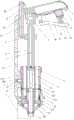
图1为本发明的主视结构示意图。FIG. 1 is a schematic view of the front structure of the present invention.
图2为本发明圆筒的俯视结构示意图。FIG. 2 is a schematic top view of the structure of the cylinder of the present invention.
图3为本发明A部分放大示意图。Figure 3 is an enlarged schematic view of part A of the present invention.
附图标记中:1空心把手,2减速电机,3六棱杆,4六棱孔套,5轴承座,6第一弹簧,7批头,8驱动装置,81握把,82储液框,83连接杆,84第一活塞,85第二弹簧,86出液管,87缸体,88第二活塞,89L型杆,9弧形板,10推动装置,101连杆,102锥形罩,103环形滑槽,104滑块,105圆筒,106放置盲孔,107第一通孔,108空心管,109第二通孔,1010挡板,1011齿轮,1012齿条,1013圆环,1014转动板,1015第三通孔,1016异型槽,1017滑杆,1018接触块,1019弧形块,1020第三弹簧,11第一凹槽,12摆动板,13第四弹簧,14第二凹槽,15卡块,16卡槽,17第五弹簧。In the reference numerals: 1 hollow handle, 2 reduction motor, 3 hexagonal rod, 4 hexagonal hole sleeve, 5 bearing seat, 6 first spring, 7 batch head, 8 driving device, 81 grip, 82 liquid storage frame, 83 connecting rod, 84 first piston, 85 second spring, 86 liquid outlet pipe, 87 cylinder block, 88 second piston, 89 L type rod, 9 arc plate, 10 push device, 101 connecting rod, 102 conical cover, 103 annular chute, 104 slider, 105 cylinder, 106 blind hole, 107 first through hole, 108 hollow tube, 109 second through hole, 1010 baffle, 1011 gear, 1012 rack, 1013 ring, 1014 Rotating plate, 1015 third through hole, 1016 special-shaped groove, 1017 sliding rod, 1018 contact block, 1019 arc block, 1020 third spring, 11 first groove, 12 swing plate, 13 fourth spring, 14 second concave Slot, 15 block, 16 card slot, 17 fifth spring.
具体实施方式Detailed ways
下面参照附图对本发明的实施例进行详细描述。Embodiments of the present invention will be described in detail below with reference to the accompanying drawings.
实施例1Example 1
一种装配用螺丝钉枪,如图1所示,包括有空心把手1、减速电机2、六棱杆3、六棱孔套4、轴承座5、第一弹簧6、批头7、驱动装置8和弧形板9,空心把手1底部左侧安装有减速电机2,减速电机2的输出轴上安装有六棱杆3,六棱杆3上滑动式设有六棱孔套4,六棱孔套4上部安装有轴承座5,六棱杆3底端与六棱孔套4内底部之间连接有第一弹簧6,六棱孔套4外底部安装有批头7,空心把手1下方设有驱动装置8,其中所述驱动装置8用于驱动六棱孔套4向下滑动,空心把手1右侧铰接连接有弧形板9,弧形板9与空心把手1配合。A screw gun for assembly, as shown in Figure 1, includes a hollow handle 1, a
驱动装置8包括有握把81、储液框82、连接杆83、第一活塞84、第二弹簧85、出液管86、缸体87、第二活塞88和L型杆89,空心把手1下方铰接连接有握把81,空心把手1底部右侧安装有储液框82,握把81顶部右侧安装有连接杆83,连接杆83上部位于储液框82内,储液框82内滑动式设有第一活塞84,连接杆83顶端与第一活塞84底部连接,握把81顶部右侧与储液框82底部之间连接有第二弹簧85,储液框82左壁安装有出液管86,出液管86与储液框82相通,出液管86位于空心把手1后侧,空心把手1左侧安装有缸体87,出液管86末端与缸体87上部右侧连接,出液管86与缸体87内相通,缸体87内滑动式设有第二活塞88,第二活塞88底部安装有L型杆89,L型杆89穿过缸体87底部,L型杆89底部与轴承座5左侧连接。The
操作者使用螺钉将两块工件固定时,首先操作者握住空心把手1,再打开弧形板9将空心把手1内的螺钉取出,螺钉取出后,操作者关闭弧形板9,用另一只手将螺钉放置于需要固定的位置,再使批头7与螺钉顶部的槽配合,然后启动减速电机2,减速电机2转动带动六棱杆3转动,六棱杆3转动带动六棱孔套4转动,从而使内螺钉转动,操作者再向内按压握把81,握把81右部向上摆动,第二弹簧85随之压缩,通过连接杆83带动第一活塞84在储液框82内向上移动,从而使储液框82内的液压油通过出液管86流至缸体87内,从而使第二活塞88向下移动,第二活塞88向下移动带动L型杆89向下移动,L型杆89向下移动通过轴承座5带动六棱孔套4向下移动,第一弹簧6被拉伸,从而使螺钉钻入需要固定的位置,当螺钉固定完成后,操作者关闭减速电机2,操作者松开握把81,握把81的右部在第二弹簧85的作用下向下摆动,握把81摆动带动连接杆83向下移动,连接杆83向下移动带动第一活塞84在储液框82内向下移动,从而将缸体87内的液压油通过出液管86抽入储液框82内,在缸体87内的液压油流入至储液框82内的过程中,六棱孔套4在第一弹簧6复位的作用下向上移动,从而使L型杆89带动第二活塞88在缸体87内向上移动复位,这样便能使六棱孔套4复位,操作者重复以上动作即可使用本设备来驱动螺钉钻入工件内,对工件进行固定。When the operator uses screws to fix the two workpieces, first the operator holds the hollow handle 1, and then opens the arc plate 9 to take out the screw in the hollow handle 1. After the screw is taken out, the operator closes the arc plate 9 and uses another Place the screw in the position that needs to be fixed with one hand, and then match the bit 7 with the groove on the top of the screw, then start the
实施例2Example 2
在实施例1的基础上,如图1-3所示,还包括有推动装置10,推动装置10包括有连杆101、锥形罩102、滑块104、圆筒105、空心管108、挡板1010、齿轮1011、齿条1012、圆环1013、转动板1014、滑杆1017、接触块1018、弧形块1019和第三弹簧1020,缸体87左侧安装有连杆101,连杆101底部右侧安装有锥形罩102,锥形罩102内底部开有环形滑槽103,环形滑槽103内滑动式设有滑块104,滑块104顶部安装有圆筒105,圆筒105顶部开有十五个放置盲孔106,圆筒105顶部中间开有第一通孔107,锥形罩102中部嵌入式安装有空心管108,空心管108上部位于第一通孔107内,圆筒105下部开有十五个第二通孔109,第二通孔109与放置盲孔106内相通,第二通孔109内铰接连接有挡板1010,挡板1010与第二通孔109铰接处安装有齿轮1011,齿轮1011与挡板1010连接,第二通孔109内滑动式安装有齿条1012,齿条1012与齿轮1011啮合,圆筒105外侧滑动式设有圆环1013,圆环1013内侧与齿条1012外侧连接,圆环1013右侧铰接连接有转动板1014,空心管108左侧上部开有第三通孔1015,圆筒105内也开有第三通孔1015,圆筒105下部开有十五个异型槽1016,异型槽1016与放置盲孔106内相通,异型槽1016内滑动式设有滑杆1017,滑杆1017内侧安装有接触块1018,连杆101右侧下部安装有弧形块1019,弧形块1019位于锥形罩102上方,弧形块1019与滑杆1017接触配合,接触块1018外侧与异型槽1016内壁之间连接有第三弹簧1020。On the basis of Embodiment 1, as shown in Figures 1-3, a pushing
操作者将螺钉放入圆筒105上的放置盲孔106内上部后,再通过拉动转动板1014带动圆环1013向上移动,圆环1013向上移动带动齿条1012向上移动,齿条1012向上移动带动齿轮1011顺时针转动,齿轮1011顺时针转动带动挡板1010顺时针转动,从而使得挡板1010不再挡住放置盲孔106中部,进而使放置盲孔106内上部的螺钉落入至放置盲孔106内下部,使每个放置盲孔106内下部只有一个螺钉,再向下按压圆环1013,圆环1013向下移动带动齿条1012向下移动,齿条1012向下移动带动齿轮1011逆时针转动,齿轮1011逆时针转动带动挡板1010逆时针转动至挡住放置盲孔106,然后顺时针转动圆筒105,滑块104在环形滑槽103内顺时针转动,从而使滑杆1017与弧形块1019接触,随着操作者将圆筒105顺时针转动至第三通孔1015处时,滑杆1017在异型槽1016内向内移动,第三弹簧1020被拉伸,从而使接触块1018将螺钉通过第三通孔1015推入至空心管108内,然后通过驱动装置8将螺钉钻入需要固定的位置,当操作者固定完一处位置后需要固定下一处位置时,操作者顺时针转动圆筒105前一根滑杆1017与接触块1018脱离,前一根滑杆1017在第三弹簧1020的作用下复位,后一根滑杆1017与接触块1018配合,这样即可使操作者无需用手稳定螺钉,降低危险性。After the operator puts the screw into the upper part of the
实施例3Example 3
在实施例1和实施例2的基础上,如图1-3所示,还包括有摆动板12和第四弹簧13,空心管108下部内壁均匀间隔开有第一凹槽11,第一凹槽11内转动式安装有摆动板12,摆动板12外侧与第一凹槽11内壁之间连接有第四弹簧13。On the basis of Embodiment 1 and
还包括有卡块15和第五弹簧17,连杆101右侧下部开有第二凹槽14,第二凹槽14内滑动式设有卡块15,卡块15左端与第二凹槽14内壁之间连接有第五弹簧17,圆筒105上部开有十五个卡槽16,十五个卡槽16与十五个放置盲孔106对应,卡槽16与卡块15配合。It also includes a blocking
当螺钉落至空心管108内时,摆动板12能够防止螺钉直接落下,当批头7带动螺钉向下移动时,摆动板12向下摆动,第四弹簧13被压缩,当批头7不再与摆动板12接触时,摆动板12在第四弹簧13的作用下复位。When the screw falls into the
当操作者不断的顺时针转动圆筒105时,卡块15与卡槽16不配合时,卡块15便会往左移动,第五弹簧17随之压缩,当圆筒105继续顺时针旋转,当卡槽16位于卡块15的右方时,在第五弹簧17的作用下,便可使得卡块15卡入卡槽16内,此时两个第三通孔1015正好对应,同时也可使操作者知晓螺钉被推入至空心管108内,操作者不断的转动圆筒105即可知晓螺钉是否被推入至空心管108内。When the operator continuously rotates the
应理解,该实施例仅用于说明本发明而不用于限制本发明的范围。此外应理解,在阅读了本发明讲授的内容之后,本领域技术人员可以对本发明作各种改动或修改,这些等价形式同样落于本申请所附权利要求书所限定的范围。It should be understood that this embodiment is only used to illustrate the present invention and not to limit the scope of the present invention. In addition, it should be understood that after reading the content taught by the present invention, those skilled in the art can make various changes or modifications to the present invention, and these equivalent forms also fall within the scope defined by the appended claims of the present application.
Claims (4)
Priority Applications (1)
| Application Number | Priority Date | Filing Date | Title |
|---|---|---|---|
| CN201910753058.6ACN110576405B (en) | 2019-08-15 | 2019-08-15 | A screw gun for assembly |
Applications Claiming Priority (1)
| Application Number | Priority Date | Filing Date | Title |
|---|---|---|---|
| CN201910753058.6ACN110576405B (en) | 2019-08-15 | 2019-08-15 | A screw gun for assembly |
Publications (2)
| Publication Number | Publication Date |
|---|---|
| CN110576405A CN110576405A (en) | 2019-12-17 |
| CN110576405Btrue CN110576405B (en) | 2020-12-08 |
Family
ID=68811266
Family Applications (1)
| Application Number | Title | Priority Date | Filing Date |
|---|---|---|---|
| CN201910753058.6AActiveCN110576405B (en) | 2019-08-15 | 2019-08-15 | A screw gun for assembly |
Country Status (1)
| Country | Link |
|---|---|
| CN (1) | CN110576405B (en) |
Families Citing this family (1)
| Publication number | Priority date | Publication date | Assignee | Title |
|---|---|---|---|---|
| EP4052851A1 (en) | 2021-03-04 | 2022-09-07 | Max Co., Ltd. | Fastening tool |
Citations (9)
| Publication number | Priority date | Publication date | Assignee | Title |
|---|---|---|---|---|
| GB1187585A (en)* | 1966-08-17 | 1970-04-08 | Gkn Screws Fasteners Ltd | New or improved Tool for Driving Fasteners and the like with Impact and/or Rotary Motion |
| DE3214696A1 (en)* | 1981-06-12 | 1982-12-30 | VEB dkk Scharfenstein, DDR 9366 Scharfenstein | Hydraulic screwdriver |
| EP0088836B1 (en)* | 1982-03-11 | 1986-09-24 | Katsuyuki Totsu | An electrically driven screw-driver |
| US5239900A (en)* | 1991-10-01 | 1993-08-31 | James Macris | Power screwdriver automatic loading apparatus |
| WO2005051606A1 (en)* | 2003-11-27 | 2005-06-09 | Robert Bosch Gmbh | Hand-held drilling and screw driving machine |
| CN201013699Y (en)* | 2007-02-01 | 2008-01-30 | 黄世忠 | Screw belt and screw gun thereof |
| CN103459096A (en)* | 2011-03-31 | 2013-12-18 | 英格索尔-兰德公司 | Display assemblies having integrated display covers and light pipes and handheld power tools and methods including same |
| CN104985554B (en)* | 2015-07-17 | 2017-03-15 | 江苏省电力公司检修分公司 | A kind of aerial lift device with insulated arm livewire work hydraulic spanner |
| CN208304901U (en)* | 2018-05-24 | 2019-01-01 | 杭州怡田工具制造有限公司 | A kind of automatic nail feeding apparatus being installed on electric screw driver |
- 2019
- 2019-08-15CNCN201910753058.6Apatent/CN110576405B/enactiveActive
Patent Citations (9)
| Publication number | Priority date | Publication date | Assignee | Title |
|---|---|---|---|---|
| GB1187585A (en)* | 1966-08-17 | 1970-04-08 | Gkn Screws Fasteners Ltd | New or improved Tool for Driving Fasteners and the like with Impact and/or Rotary Motion |
| DE3214696A1 (en)* | 1981-06-12 | 1982-12-30 | VEB dkk Scharfenstein, DDR 9366 Scharfenstein | Hydraulic screwdriver |
| EP0088836B1 (en)* | 1982-03-11 | 1986-09-24 | Katsuyuki Totsu | An electrically driven screw-driver |
| US5239900A (en)* | 1991-10-01 | 1993-08-31 | James Macris | Power screwdriver automatic loading apparatus |
| WO2005051606A1 (en)* | 2003-11-27 | 2005-06-09 | Robert Bosch Gmbh | Hand-held drilling and screw driving machine |
| CN201013699Y (en)* | 2007-02-01 | 2008-01-30 | 黄世忠 | Screw belt and screw gun thereof |
| CN103459096A (en)* | 2011-03-31 | 2013-12-18 | 英格索尔-兰德公司 | Display assemblies having integrated display covers and light pipes and handheld power tools and methods including same |
| CN104985554B (en)* | 2015-07-17 | 2017-03-15 | 江苏省电力公司检修分公司 | A kind of aerial lift device with insulated arm livewire work hydraulic spanner |
| CN208304901U (en)* | 2018-05-24 | 2019-01-01 | 杭州怡田工具制造有限公司 | A kind of automatic nail feeding apparatus being installed on electric screw driver |
Also Published As
| Publication number | Publication date |
|---|---|
| CN110576405A (en) | 2019-12-17 |
Similar Documents
| Publication | Publication Date | Title |
|---|---|---|
| CN213105522U (en) | Aluminum alloy door and window drilling equipment that polishes | |
| CN208163874U (en) | A kind of door-plate multi-directional drilling device | |
| CN110576405B (en) | A screw gun for assembly | |
| CN218135108U (en) | Drilling equipment is used in chain processing | |
| CN208002894U (en) | A kind of wall hanging rack of medical instrument | |
| CN208409211U (en) | Vehicle right and left lateral coaming plate unit fixture | |
| CN110695028A (en) | High-efficient belt cleaning device of irregular vase | |
| CN110281013A (en) | A kind of numerically-controlled machine tool of boring and milling one | |
| CN209335798U (en) | A kind of plate drilling device | |
| CN217967356U (en) | Perforating device for processing PE pipe | |
| CN215746523U (en) | A drilling device for motor end cover processing | |
| CN212131485U (en) | Auxiliary opening and closing device convenient to adjust for underground valve | |
| CN212042807U (en) | A flange hole machining and positioning fixture in an electric regulating valve | |
| CN210938064U (en) | Turntable machine combined machine tool | |
| CN211304865U (en) | A punching machine for processing hardware rigging | |
| CN221312200U (en) | Electrode copper pipe flaring device | |
| CN209050150U (en) | A kind of cylinder head cover drilling machine of rotatable positioning | |
| CN208117308U (en) | A kind of perforating device of the precision machinery basic part processing convenient for fixation | |
| CN105747929A (en) | Egg washer | |
| CN214914299U (en) | a bag filter | |
| CN220461671U (en) | Rotating frame of cleaning equipment | |
| CN221640283U (en) | Intelligent drilling machine convenient to maintain | |
| CN220805763U (en) | A tapping mechanism | |
| CN212577585U (en) | A workbench for a special opening drilling die for leading edge rib | |
| CN217123414U (en) | In-line tool changer intelligent single-head hinged drill |
Legal Events
| Date | Code | Title | Description |
|---|---|---|---|
| PB01 | Publication | ||
| PB01 | Publication | ||
| SE01 | Entry into force of request for substantive examination | ||
| SE01 | Entry into force of request for substantive examination | ||
| TA01 | Transfer of patent application right | Effective date of registration:20201123 Address after:344300 West Side of Lezeng Highway in Le'an County Industrial Park, Fuzhou City, Jiangxi Province Applicant after:Jiangxi Wanshang Industrial Co.,Ltd. Address before:Heishijiao street Shahekou Dalian District 116023 of Liaoning Province, No. 52 Dalian Ocean University Applicant before:Chen Hui | |
| TA01 | Transfer of patent application right | ||
| GR01 | Patent grant | ||
| GR01 | Patent grant | ||
| PE01 | Entry into force of the registration of the contract for pledge of patent right | Denomination of invention:A screw gun for assembly Granted publication date:20201208 Pledgee:Agricultural Bank of China Limited Le'an County sub branch Pledgor:Jiangxi Wanshang Industrial Co.,Ltd. Registration number:Y2024980003564 | |
| PE01 | Entry into force of the registration of the contract for pledge of patent right | ||
| PC01 | Cancellation of the registration of the contract for pledge of patent right | Granted publication date:20201208 Pledgee:Agricultural Bank of China Limited Le'an County sub branch Pledgor:Jiangxi Wanshang Industrial Co.,Ltd. Registration number:Y2024980003564 | |
| PC01 | Cancellation of the registration of the contract for pledge of patent right |