CN110571628B - A Frequency Tunable Photoelectric Oscillator System Based on Electrical Gain Frequency Selective Cavity - Google Patents
A Frequency Tunable Photoelectric Oscillator System Based on Electrical Gain Frequency Selective CavityDownload PDFInfo
- Publication number
- CN110571628B CN110571628BCN201910820050.7ACN201910820050ACN110571628BCN 110571628 BCN110571628 BCN 110571628BCN 201910820050 ACN201910820050 ACN 201910820050ACN 110571628 BCN110571628 BCN 110571628B
- Authority
- CN
- China
- Prior art keywords
- electric
- frequency
- oeo
- microwave
- cavity
- Prior art date
- Legal status (The legal status is an assumption and is not a legal conclusion. Google has not performed a legal analysis and makes no representation as to the accuracy of the status listed.)
- Active
Links
Images


Classifications
- H—ELECTRICITY
- H01—ELECTRIC ELEMENTS
- H01S—DEVICES USING THE PROCESS OF LIGHT AMPLIFICATION BY STIMULATED EMISSION OF RADIATION [LASER] TO AMPLIFY OR GENERATE LIGHT; DEVICES USING STIMULATED EMISSION OF ELECTROMAGNETIC RADIATION IN WAVE RANGES OTHER THAN OPTICAL
- H01S1/00—Masers, i.e. devices using stimulated emission of electromagnetic radiation in the microwave range
- H01S1/02—Masers, i.e. devices using stimulated emission of electromagnetic radiation in the microwave range solid
Landscapes
- Physics & Mathematics (AREA)
- Electromagnetism (AREA)
- Optics & Photonics (AREA)
- Optical Communication System (AREA)
Abstract
Description
Translated fromChinese技术领域technical field
本发明涉及一种基于电增益选频腔的频率可调谐光电振荡器系统。The invention relates to a frequency tunable photoelectric oscillator system based on an electric gain frequency selective cavity.
背景技术Background technique
高性能微波源作为一切微波领域应用的基础,其相位噪声、频谱纯度和稳定性等指标直接影响航空航天、仪器测量、雷达等诸多领域中电子设备的性能。随着应用需求的提高,传统微波源的噪声性能已接近极限。光电振荡器(OEO)是一种高频谱纯度的新型微波信号发生器,其Q值高达1010量级,能够产生频率高达数百GHz的微波信号,且相位噪声低于-160dBc/Hz@10kHz,是一种非常理想的高性能微波振荡器。High-performance microwave sources are the basis of all microwave applications, and their phase noise, spectral purity and stability directly affect the performance of electronic equipment in many fields such as aerospace, instrument measurement, and radar. As application demands increase, the noise performance of traditional microwave sources is approaching its limit. Optical Oscillator (OEO) is a new type of microwave signal generator with high spectral purity. Its Q value is as high as 1010 , and it can generate microwave signals with frequencies up to hundreds of GHz, and the phase noise is lower than -160dBc/Hz@10kHz , is a very ideal high-performance microwave oscillator.
在通信领域容量扩充需要的频分复用、雷达侦测等各项应用中,都需要用到频率可调谐的信号源,频率的可调谐性也是衡量各类微波、毫米波产生器件性能的重要标准之一。随着OEO相位噪声和边模抑制性能的不断完善,其频率可调谐性成为了其实用化的阻碍,如何在兼顾其低相位噪声和高边模抑制性能的同时产生频率可调谐的振荡信号成为了人们的研究热点。In various applications such as frequency division multiplexing and radar detection required for capacity expansion in the communication field, frequency tunable signal sources are required. Frequency tunability is also an important measure of the performance of various microwave and millimeter wave generating devices. one of the standards. With the continuous improvement of OEO's phase noise and side-mode suppression performance, its frequency tunability has become an obstacle to its practical application. How to generate a frequency-tunable oscillation signal while taking into account its low phase noise and high side-mode suppression performance people's research hotspots.
为了实现OEO输出频率的可调谐,研究人员相继提出基于YIG电可调滤波器的OEO方案和基于相移光栅的可调谐OEO方案。这两种方案均采用了双环路OEO架构,增加了系统的成本和复杂性。前一种方案输出信号的频率可调范围及步进完全由YIG滤波器的性能决定,系统性能完全受YIG电可调滤波器的限制;后一种方案中相移光栅对于光源稳定度要求比较高,对于环境变化较为敏感,信号稳定性较差。为了避免上述情况,又提出了基于DFB腔注入锁定效应的可调谐OEO的方案,该方案中通过注入锁定实现边模抑制,调节注入光波长和功率实现输出信号的频率可调谐。但由于无法精细控制注入光波长和功率,输出信号的调谐步进非常大。In order to realize the tunable output frequency of OEO, researchers successively proposed an OEO scheme based on YIG electrically tunable filter and a tunable OEO scheme based on phase-shift grating. Both schemes use a dual-loop OEO architecture, which increases the cost and complexity of the system. The frequency adjustable range and step of the output signal of the former scheme are completely determined by the performance of the YIG filter, and the system performance is completely limited by the YIG electrically tunable filter; in the latter scheme, the phase-shift grating requires a comparison of the light source stability High, it is more sensitive to environmental changes, and the signal stability is poor. In order to avoid the above situation, a tunable OEO scheme based on the injection locking effect of DFB cavity is proposed. In this scheme, side mode suppression is achieved by injection locking, and the frequency of the output signal is tunable by adjusting the wavelength and power of the injected light. However, since the wavelength and power of the injected light cannot be finely controlled, the tuning step of the output signal is very large.
发明内容SUMMARY OF THE INVENTION
针对上述现有技术,本发明提出一种基于电增益选频腔的频率可调谐光电振荡器系统,解决了现有可调谐微波源技术无法同时满足低相位噪声和高边模抑制比的问题,本发明的系统结构简单易实现,通过控制电移相器和光延时线可以实现精细调谐,同时既保留了OEO低相位噪声的优势,又能有效抑制边模,具有很高的系统稳定性,本发明可以作为一种稳定的产生高质量可调谐输出信号的信号发生器。In view of the above prior art, the present invention proposes a frequency tunable photoelectric oscillator system based on an electrical gain frequency selective cavity, which solves the problem that the existing tunable microwave source technology cannot satisfy both low phase noise and high side mode suppression ratio. The system structure of the present invention is simple and easy to implement, and fine tuning can be realized by controlling the electrical phase shifter and the optical delay line, and at the same time, the advantages of low phase noise of OEO are retained, and side modes can be effectively suppressed, and the system has high stability. The present invention can be used as a stable signal generator for generating high-quality tunable output signals.
为了解决上述技术问题,本发明提出的一种基于电增益选频腔的频率可调谐光电振荡器系统,包括如下的光学器件和电子器件:激光器、强度调制器、单模光纤、可调光衰减器、光延时线、光电探测器、带通滤波器、五个微波放大器、三个功分器和两个电衰减器;其中五个微波放大器记作第一微波放大器、第二微波放大器、第三微波放大器、第四微波放大器和第五微波放大器,三个功分器记作第一功分器、第二功分器和第三功分器,两个电衰减器记作第一电衰减器和第二电衰减器;所述强度调制器将激光器输出的光信号进行调制后,依次经过所述单模光纤、可调光衰减器和光延时线后由所述光电探测器光电转换输出微波信号,光电探测器输出的微波信号经过第一微波放大器放大后依次通过第一功分器和带通滤波器,所述带通滤波器选出相应的频率后经过所述第二功分器分为两路;一路通过第四微波放大器、第三功分器和第五微波放大器反馈至所述强度调制器,形成OEO谐振腔;另一路通过所述第一电衰减器、第二微波放大器、电移相器、第三微波放大器和第二电衰减器后反馈给所述第一功分器,形成电增益选频腔;OEO谐振腔自由振荡信号与电增益选频腔输出的信号产生电注入锁定效应,通过调节电移相器改变电增益选频腔的输出频率,通过调节光延时线使OEO起振模式与电增益选频腔进行匹配,最终由第三功分器输出具有低相噪和高边模抑制比的频率可调信号。In order to solve the above technical problems, a frequency tunable optoelectronic oscillator system based on an electrical gain frequency selective cavity proposed by the present invention includes the following optical devices and electronic devices: laser, intensity modulator, single-mode fiber, adjustable optical attenuation , optical delay line, photodetector, band-pass filter, five microwave amplifiers, three power dividers and two electrical attenuators; the five microwave amplifiers are denoted as the first microwave amplifier, the second microwave amplifier, The third microwave amplifier, the fourth microwave amplifier and the fifth microwave amplifier, the three power dividers are recorded as the first power divider, the second power divider and the third power divider, and the two electrical attenuators are recorded as the first power divider an attenuator and a second electrical attenuator; after the intensity modulator modulates the optical signal output by the laser, it is converted into photoelectricity by the photodetector after passing through the single-mode fiber, the adjustable optical attenuator and the optical delay line in sequence The microwave signal is output, and the microwave signal output by the photodetector is amplified by the first microwave amplifier and then passes through the first power divider and the band-pass filter in turn. The band-pass filter selects the corresponding frequency and passes through the second power divider The device is divided into two channels; one is fed back to the intensity modulator through the fourth microwave amplifier, the third power divider and the fifth microwave amplifier to form an OEO resonant cavity; the other is through the first electrical attenuator, the second microwave The amplifier, the electrical phase shifter, the third microwave amplifier and the second electrical attenuator are fed back to the first power divider to form an electrical gain frequency selective cavity; the free oscillation signal of the OEO resonator cavity and the signal output by the electrical gain frequency selective cavity The electrical injection locking effect is generated, the output frequency of the electrical gain frequency selective cavity is changed by adjusting the electrical phase shifter, and the OEO start-up mode is matched with the electrical gain frequency selective cavity by adjusting the optical delay line, and finally the output of the third power divider Frequency tunable signal with low phase noise and high side mode rejection ratio.
与现有技术相比,本发明的有益效果是:Compared with the prior art, the beneficial effects of the present invention are:
由于本发明将单环OEO与电增益选频腔结合,通过调节移相器和光延时线控制OEO环腔和电增益选频腔的腔长,改变两者输出频率,根据电注入锁定原理,实现输出信号频率可调谐。其次,通过调节电增益选频腔增益使OEO环腔增益与其达到最佳匹配状态,取得更好地边模抑制效果。有效解决了现有可调谐微波源技术无法同时满足低相位噪声和高边模抑制比的问题。Because the invention combines the single-loop OEO with the electrical gain frequency selective cavity, and controls the cavity length of the OEO ring cavity and the electrical gain frequency selective cavity by adjusting the phase shifter and the optical delay line, and changes the output frequencies of the two, according to the principle of electrical injection locking, The output signal frequency can be tunable. Secondly, the gain of the OEO ring cavity is optimally matched with the gain of the frequency-selective cavity by adjusting the electrical gain, and a better side-mode suppression effect is obtained. It effectively solves the problem that the existing tunable microwave source technology cannot satisfy the low phase noise and the high side mode suppression ratio at the same time.
附图说明Description of drawings
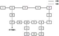
图1为本发明基于电增益选频腔的频率可调谐光电振荡器系统框图;1 is a block diagram of a frequency tunable optoelectronic oscillator system based on an electrical gain frequency selective cavity of the present invention;
图2是调节电移相器之后的输出信号频谱图;Fig. 2 is the output signal spectrogram after adjusting the electric phase shifter;
图3是调节电移相器之前的输出信号频谱图;Fig. 3 is the output signal spectrogram before adjusting the electrical phase shifter;
图4是输出信号的相位噪声图。Figure 4 is a phase noise plot of the output signal.
图中:1-激光器,2-强度调制器,3-单模光纤,4-可调光衰减器,5-光延时线,6-光电探测器,7-第一微波放大器,8-第一功分器,9-带通滤波器,10-第二功分器,11-第一电衰减器,12-第二微波放大器,13-电移相器,14-第三微波放大器,15-第二电衰减器,16-第四微波放大器,17-第三功分器,18-第五微波放大器。In the figure: 1-laser, 2-intensity modulator, 3-single-mode fiber, 4-tunable optical attenuator, 5-optical delay line, 6-photodetector, 7-first microwave amplifier, 8-th A power divider, 9-band-pass filter, 10-second power divider, 11-first electrical attenuator, 12-second microwave amplifier, 13-electrical phase shifter, 14-third microwave amplifier, 15 - 2nd electrical attenuator, 16- 4th microwave amplifier, 17- 3rd power divider, 18- 5th microwave amplifier.
具体实施方式Detailed ways
下面结合附图及具体实施例对本发明做进一步的说明,但下述实施例绝非对本发明有任何限制。The present invention will be further described below with reference to the accompanying drawings and specific embodiments, but the following embodiments do not limit the present invention by any means.
如图1所示,本发明提出的一种基于电增益选频腔的频率可调谐光电振荡器系统是基于电注入锁定原理,通过调节光延时线和移相器使OEO自由振荡信号与电增益选频腔输出信号满足电注入锁定条件,改变输出信号频率,实现输出频率可调谐。As shown in Figure 1, a frequency tunable optoelectronic oscillator system based on an electrical gain frequency selective cavity proposed by the present invention is based on the principle of electrical injection locking. By adjusting the optical delay line and phase shifter, the OEO free oscillation signal and electrical The output signal of the gain frequency selective cavity satisfies the electrical injection locking condition, changes the frequency of the output signal, and realizes the tunable output frequency.
该系统包括如下的光学器件和电子器件:激光器1、强度调制器2、单模光纤3、可调光衰减器4、光延时线5、光电探测器6、带通滤波器9、五个微波放大器、三个功分器和两个电衰减器;其中五个微波放大器记作第一微波放大器7、第二微波放大器12、第三微波放大器14、第四微波放大器16和第五微波放大器18,三个功分器记作第一功分器8、第二功分器10和第三功分器17,两个电衰减器记作第一电衰减器11和第二电衰减器15。The system includes the following optical devices and electronic devices:
本发明中,所述激光器1、强度调制器2、单模光纤3、可调光衰减器4、光延时线5、光电探测器6、第一微波放大器7、第一功分器8、带通滤波器9、第二功分器10,第四微波放大器16,第三功分器17和第五微波放大器18构成OEO谐振腔。所述第一功分器8,带通滤波器9,第二功分器10,电衰减器11,第二微波放大器12,电移相器13,第三微波放大器14,第二电衰减器15构成电增益选频腔。In the present invention, the
具体实现的过程是,The specific implementation process is,
所述激光器1输出的光信号先注入强度调制器2,从而对光信号进行调制,强度调制器3输出的调制光通过所述单模光纤3和可调光衰减器4进行衰减;所述光延时线5对从可调光衰减器4衰减后输出的光信号进行传输时延匹配,光延时线5输出的光信号注入到所述光电探测器6中,将光信号转换成微波信号;光电探测器6输出的微波信号经过第一微波放大器7放大后依次通过第一功分器8和带通滤波器9,所述带通滤波器9选出相应的频率后经过所述第二功分器10分为两路;一路通过第四微波放大器16、第三功分器17和第五微波放大器18反馈至所述强度调制器2,形成OEO谐振腔;The optical signal output by the
另一路通过所述第一电衰减器11、第二微波放大器12、电移相器13、第三微波放大器14和第二电衰减器15后反馈给所述第一功分器8,形成电增益选频腔;The other path is fed back to the
OEO谐振腔自由振荡信号与电增益选频腔输出的信号产生电注入锁定效应,通过调节电移相器13改变电增益选频腔的输出频率,通过调节光延时线5使OEO起振模式与电增益选频腔进行匹配,最终由第三功分器17输出具有低相噪和高边模抑制比的频率可调信号。The free oscillation signal of the OEO resonator and the signal output by the electrical gain frequency selective cavity produce an electrical injection locking effect. The output frequency of the electrical gain frequency selective cavity is changed by adjusting the
本发明中,将单环OEO与一个由微波滤波器、电衰减器和电移相器等器件构成的电增益选频腔结合,通过电增益选频腔信号与OEO自由振荡信号的电注入锁定实现系统信号的输出,调节电移相器13的偏置电压可以改变电选频腔腔长,从而改变腔内微波信号的频率;同时调节光延时线5改变OEO的起振模式,实现两环路频率的匹配。如图2所示,通过调节电移相器13和光延时线5即可实现输出信号的频率调谐。调节第一和第二电衰减器11、12匹配OEO谐振腔增益与电增益选频腔达到最佳匹配状态,可以改善边模抑制效果,如图3和图4所示,系统输出信号频率可调谐的同时具有低相位噪声和高边模抑制比。本发明系统结构简单,既保留了单环OEO低相位噪声的优势,又能有效抑制边模,为频率可调谐OEO提供了一种新的实现方法。In the present invention, a single-loop OEO is combined with an electrical gain frequency selective cavity composed of a microwave filter, an electrical attenuator, an electrical phase shifter and other devices, and the electrical gain frequency selective cavity signal is locked by the electrical injection of the OEO free oscillation signal. To achieve the output of the system signal, adjusting the bias voltage of the
尽管上面结合附图对本发明进行了描述,但是本发明并不局限于上述的具体实施方式,上述的具体实施方式仅仅是示意性的,而不是限制性的,本领域的普通技术人员在本发明的启示下,在不脱离本发明宗旨的情况下,还可以做出很多变形,这些均属于本发明的保护之内。Although the present invention has been described above in conjunction with the accompanying drawings, the present invention is not limited to the above-mentioned specific embodiments, which are merely illustrative rather than restrictive. Under the inspiration of the present invention, many modifications can be made without departing from the spirit of the present invention, which all belong to the protection of the present invention.
Claims (1)
Priority Applications (1)
| Application Number | Priority Date | Filing Date | Title |
|---|---|---|---|
| CN201910820050.7ACN110571628B (en) | 2019-08-31 | 2019-08-31 | A Frequency Tunable Photoelectric Oscillator System Based on Electrical Gain Frequency Selective Cavity |
Applications Claiming Priority (1)
| Application Number | Priority Date | Filing Date | Title |
|---|---|---|---|
| CN201910820050.7ACN110571628B (en) | 2019-08-31 | 2019-08-31 | A Frequency Tunable Photoelectric Oscillator System Based on Electrical Gain Frequency Selective Cavity |
Publications (2)
| Publication Number | Publication Date |
|---|---|
| CN110571628A CN110571628A (en) | 2019-12-13 |
| CN110571628Btrue CN110571628B (en) | 2020-09-15 |
Family
ID=68777157
Family Applications (1)
| Application Number | Title | Priority Date | Filing Date |
|---|---|---|---|
| CN201910820050.7AActiveCN110571628B (en) | 2019-08-31 | 2019-08-31 | A Frequency Tunable Photoelectric Oscillator System Based on Electrical Gain Frequency Selective Cavity |
Country Status (1)
| Country | Link |
|---|---|
| CN (1) | CN110571628B (en) |
Families Citing this family (3)
| Publication number | Priority date | Publication date | Assignee | Title |
|---|---|---|---|---|
| CN111579816B (en)* | 2020-05-14 | 2022-08-30 | 天津大学 | Acceleration measuring instrument based on photoelectric oscillator |
| CN114993465B (en)* | 2022-05-31 | 2023-04-07 | 天津大学 | Ultra-weak frequency deviation optical detection system based on photoelectric oscillator |
| CN115015630B (en)* | 2022-05-31 | 2023-06-09 | 天津大学 | An ultra-weak frequency offset signal detection system and method based on a photoelectric oscillator |
Citations (5)
| Publication number | Priority date | Publication date | Assignee | Title |
|---|---|---|---|---|
| CN104752940A (en)* | 2013-12-27 | 2015-07-01 | 北京邮电大学 | Photoelectric oscillator |
| CN204615139U (en)* | 2015-04-29 | 2015-09-02 | 湖南工学院 | Photoelectric oscillator |
| WO2017031575A1 (en)* | 2015-08-21 | 2017-03-02 | Nanowave Technologies Inc. | Optoelectronic oscillator with tunable filter |
| CN107342816A (en)* | 2017-06-28 | 2017-11-10 | 天津大学 | A kind of signal generator for producing multichannel microwave signal simultaneously based on optical-electronic oscillator |
| CN109818235A (en)* | 2019-03-21 | 2019-05-28 | 中国科学院半导体研究所 | Weak signal detection and amplification system and method based on multi-mode photoelectric oscillator |
- 2019
- 2019-08-31CNCN201910820050.7Apatent/CN110571628B/enactiveActive
Patent Citations (5)
| Publication number | Priority date | Publication date | Assignee | Title |
|---|---|---|---|---|
| CN104752940A (en)* | 2013-12-27 | 2015-07-01 | 北京邮电大学 | Photoelectric oscillator |
| CN204615139U (en)* | 2015-04-29 | 2015-09-02 | 湖南工学院 | Photoelectric oscillator |
| WO2017031575A1 (en)* | 2015-08-21 | 2017-03-02 | Nanowave Technologies Inc. | Optoelectronic oscillator with tunable filter |
| CN107342816A (en)* | 2017-06-28 | 2017-11-10 | 天津大学 | A kind of signal generator for producing multichannel microwave signal simultaneously based on optical-electronic oscillator |
| CN109818235A (en)* | 2019-03-21 | 2019-05-28 | 中国科学院半导体研究所 | Weak signal detection and amplification system and method based on multi-mode photoelectric oscillator |
Also Published As
| Publication number | Publication date |
|---|---|
| CN110571628A (en) | 2019-12-13 |
Similar Documents
| Publication | Publication Date | Title |
|---|---|---|
| CN110943362B (en) | High-precision tunable low-phase-noise photo-generated microwave signal generating device and method | |
| CN109616855B (en) | A Quadruple Frequency Injection Locked Photoelectric Oscillator | |
| CN110571628B (en) | A Frequency Tunable Photoelectric Oscillator System Based on Electrical Gain Frequency Selective Cavity | |
| CN102148475B (en) | Photonic-filtering-based optoelectronic oscillator | |
| CN108712213B (en) | Microwave three/two divided-frequency method and device based on optoelectronic oscillation loop | |
| CN110011174B (en) | Optical phase locking method and device based on microwave photon frequency division | |
| CN109525244B (en) | A Coupled Photoelectric Oscillation Signal Generator with High-speed Adjustable Frequency | |
| CN111082872B (en) | Fourier domain mode-locked photoelectric oscillator based on electronic control frequency sweep and implementation method | |
| CN104410366B (en) | X-band high speed swept-frequency signal generation device and its method based on optical-electronic oscillator | |
| CN113161863B (en) | Microwave pulse generating device and method based on time domain mode locking photoelectric oscillator | |
| US7457489B2 (en) | Frequency tuning of photonic oscillator using amplifier bias voltage | |
| CN108183380B (en) | Integrated optoelectronic oscillator | |
| CN110531324A (en) | A kind of tunable linear FM signal generation system based on optical-electronic oscillator | |
| CN114784598B (en) | Parity-time symmetric optoelectronic oscillator based on intensity modulated sidebands | |
| CN112103755A (en) | Photoelectric oscillator based on directly-modulated light injection semiconductor laser | |
| CN110707509A (en) | Fourier domain mode-locked optoelectronic oscillator | |
| CN115967442A (en) | Brillouin optical fiber laser narrow-band adjustable dual-passband microwave photon filter | |
| CN103346840B (en) | A kind of device producing frequency multiplication low noise microwave signal | |
| CN111740784A (en) | An extremely narrow pulse generation system based on electro-optical modulation of microwave photonic composite modulation | |
| CN107069389A (en) | A kind of wideband adjustable optical-electronic oscillator based on microlock | |
| CN108183381A (en) | A kind of high stable optical-electronic oscillator and its method using novel feedback controling mode | |
| CN106356700A (en) | Method and device for generating high-stability microwave millimeter wave source | |
| CN113794087A (en) | PT (potential Transformer) symmetry-based tunable photoelectric oscillator realized by combining high-Q resonator | |
| RU186801U1 (en) | Radio photon microwave filter | |
| CN118156949A (en) | Phase domain mode-locked photogenerated microwave device and method |
Legal Events
| Date | Code | Title | Description |
|---|---|---|---|
| PB01 | Publication | ||
| PB01 | Publication | ||
| SE01 | Entry into force of request for substantive examination | ||
| SE01 | Entry into force of request for substantive examination | ||
| GR01 | Patent grant | ||
| GR01 | Patent grant |