CN110570010B - An energy management method for a distributed system with a heat storage device - Google Patents
An energy management method for a distributed system with a heat storage deviceDownload PDFInfo
- Publication number
- CN110570010B CN110570010BCN201910703793.6ACN201910703793ACN110570010BCN 110570010 BCN110570010 BCN 110570010BCN 201910703793 ACN201910703793 ACN 201910703793ACN 110570010 BCN110570010 BCN 110570010B
- Authority
- CN
- China
- Prior art keywords
- energy
- heat
- storage device
- heat storage
- tess
- Prior art date
- Legal status (The legal status is an assumption and is not a legal conclusion. Google has not performed a legal analysis and makes no representation as to the accuracy of the status listed.)
- Active
Links
Images


Classifications
- G—PHYSICS
- G06—COMPUTING OR CALCULATING; COUNTING
- G06Q—INFORMATION AND COMMUNICATION TECHNOLOGY [ICT] SPECIALLY ADAPTED FOR ADMINISTRATIVE, COMMERCIAL, FINANCIAL, MANAGERIAL OR SUPERVISORY PURPOSES; SYSTEMS OR METHODS SPECIALLY ADAPTED FOR ADMINISTRATIVE, COMMERCIAL, FINANCIAL, MANAGERIAL OR SUPERVISORY PURPOSES, NOT OTHERWISE PROVIDED FOR
- G06Q10/00—Administration; Management
- G06Q10/04—Forecasting or optimisation specially adapted for administrative or management purposes, e.g. linear programming or "cutting stock problem"
- G—PHYSICS
- G06—COMPUTING OR CALCULATING; COUNTING
- G06Q—INFORMATION AND COMMUNICATION TECHNOLOGY [ICT] SPECIALLY ADAPTED FOR ADMINISTRATIVE, COMMERCIAL, FINANCIAL, MANAGERIAL OR SUPERVISORY PURPOSES; SYSTEMS OR METHODS SPECIALLY ADAPTED FOR ADMINISTRATIVE, COMMERCIAL, FINANCIAL, MANAGERIAL OR SUPERVISORY PURPOSES, NOT OTHERWISE PROVIDED FOR
- G06Q10/00—Administration; Management
- G06Q10/06—Resources, workflows, human or project management; Enterprise or organisation planning; Enterprise or organisation modelling
- G06Q10/063—Operations research, analysis or management
- G06Q10/0631—Resource planning, allocation, distributing or scheduling for enterprises or organisations
- G06Q10/06313—Resource planning in a project environment
- G—PHYSICS
- G06—COMPUTING OR CALCULATING; COUNTING
- G06Q—INFORMATION AND COMMUNICATION TECHNOLOGY [ICT] SPECIALLY ADAPTED FOR ADMINISTRATIVE, COMMERCIAL, FINANCIAL, MANAGERIAL OR SUPERVISORY PURPOSES; SYSTEMS OR METHODS SPECIALLY ADAPTED FOR ADMINISTRATIVE, COMMERCIAL, FINANCIAL, MANAGERIAL OR SUPERVISORY PURPOSES, NOT OTHERWISE PROVIDED FOR
- G06Q10/00—Administration; Management
- G06Q10/06—Resources, workflows, human or project management; Enterprise or organisation planning; Enterprise or organisation modelling
- G06Q10/063—Operations research, analysis or management
- G06Q10/0631—Resource planning, allocation, distributing or scheduling for enterprises or organisations
- G06Q10/06315—Needs-based resource requirements planning or analysis
- G—PHYSICS
- G06—COMPUTING OR CALCULATING; COUNTING
- G06Q—INFORMATION AND COMMUNICATION TECHNOLOGY [ICT] SPECIALLY ADAPTED FOR ADMINISTRATIVE, COMMERCIAL, FINANCIAL, MANAGERIAL OR SUPERVISORY PURPOSES; SYSTEMS OR METHODS SPECIALLY ADAPTED FOR ADMINISTRATIVE, COMMERCIAL, FINANCIAL, MANAGERIAL OR SUPERVISORY PURPOSES, NOT OTHERWISE PROVIDED FOR
- G06Q50/00—Information and communication technology [ICT] specially adapted for implementation of business processes of specific business sectors, e.g. utilities or tourism
- G06Q50/06—Energy or water supply
Landscapes
- Business, Economics & Management (AREA)
- Human Resources & Organizations (AREA)
- Engineering & Computer Science (AREA)
- Economics (AREA)
- Strategic Management (AREA)
- Entrepreneurship & Innovation (AREA)
- Physics & Mathematics (AREA)
- Theoretical Computer Science (AREA)
- General Physics & Mathematics (AREA)
- Marketing (AREA)
- General Business, Economics & Management (AREA)
- Tourism & Hospitality (AREA)
- Development Economics (AREA)
- Game Theory and Decision Science (AREA)
- Quality & Reliability (AREA)
- Operations Research (AREA)
- Educational Administration (AREA)
- Health & Medical Sciences (AREA)
- Biodiversity & Conservation Biology (AREA)
- Public Health (AREA)
- Primary Health Care (AREA)
- Life Sciences & Earth Sciences (AREA)
- Water Supply & Treatment (AREA)
- General Health & Medical Sciences (AREA)
- Air Conditioning Control Device (AREA)
- Supply And Distribution Of Alternating Current (AREA)
Abstract
Description
Translated fromChinese技术领域technical field
本发明属于分布式系统领域,特别涉及一种含储热装置的分布式系统的能量管理方法。The invention belongs to the field of distributed systems, in particular to an energy management method of a distributed system including a heat storage device.
背景技术Background technique
分布式系统具有靠近用户、可再生能源接入性好、能源利用效率高等优势,是新能源和可再生能源系统发展的趋势。其中,以微小型燃气机组为供能主体的冷热电联供系统(Combined cooling,heating and power,CCHP)集供电、供热、供冷于一体,通过电冷热三联供的方式可实现能源的梯级利用,综合能源利用率可达70%以上,因此CCHP系统成为分布式系统发展的主流形式。Distributed systems have the advantages of being close to users, good access to renewable energy, and high energy utilization efficiency, which is the development trend of new energy and renewable energy systems. Among them, the combined cooling, heating and power (CCHP) system, which uses micro gas-fired units as the main energy supply, integrates power supply, heating, and cooling. The cascade utilization of integrated energy can reach more than 70%, so the CCHP system has become the mainstream form of distributed system development.
CCHP系统包含多能源输入和多负荷需求,产能和用能之间的不均衡问题较为突出,存在系统效率高但节能率低的普遍现象。储能技术是实现其能量优化调度的关键,而储热作为单位储能容量成本较低的方式,易于推广到实际系统中。但目前含储热装置的分布式系统控制方法未能有效发挥储热系统的作用,导致其利用率较低,无法有效实现系统能量的优化调度;同时储能系统的设计容量冗余较大,经济性较差。因此,设计一种适用于含储热装置的分布式系统能量管理方法及其容量优化匹配方法,对储能技术在分布式系统中的应用推广具有重要的意义。The CCHP system includes multi-energy input and multi-load demand, and the imbalance between production capacity and energy consumption is more prominent, and there is a common phenomenon that the system efficiency is high but the energy saving rate is low. Energy storage technology is the key to realize optimal energy dispatching, and heat storage, as a way of lower cost per unit energy storage capacity, is easy to be extended to practical systems. However, the current distributed system control method including heat storage devices fails to effectively play the role of the heat storage system, resulting in a low utilization rate and the inability to effectively achieve optimal scheduling of system energy; at the same time, the design capacity of the energy storage system is relatively large. The economy is poor. Therefore, it is of great significance to design an energy management method suitable for distributed systems with heat storage devices and its capacity optimization matching method for the application and promotion of energy storage technology in distributed systems.
发明内容Contents of the invention
本发明的目的在于提供一种含储热装置的分布式系统的能量管理方法,以实现分布式系统能量的优化调度,提高系统综合能源利用率和节能率,并减少系统投入成本。The purpose of the present invention is to provide an energy management method for a distributed system including a heat storage device, so as to realize optimal dispatching of distributed system energy, improve system comprehensive energy utilization rate and energy saving rate, and reduce system input cost.
为实现上述目的,本发明采取的技术方案是:For realizing above-mentioned object, the technical scheme that the present invention takes is:
该分布式系统包括:燃气机组、余热回收装置、燃气锅炉、吸收式制冷机、热交换器、储热装置。燃气机组连接燃气管网获取天然气、产生电能并由余热回收装置将余热进行回收;燃气锅炉连接燃气管网获取天然气,产生热能。燃气机组和电网提供电能满足用户电负荷需求;余热回收装置和燃气锅炉提供热能,且通过吸收式制冷机转换为合适的冷能满足用户冷负荷需求、通过热交换器转换为合适的热能满足用户热负荷需求。提供用户的热能可通过储热装置进行调节。The distributed system includes: gas-fired unit, waste heat recovery device, gas-fired boiler, absorption refrigerator, heat exchanger, and heat storage device. The gas-fired unit is connected to the gas pipeline network to obtain natural gas, generate electric energy, and the waste heat is recovered by the waste heat recovery device; the gas-fired boiler is connected to the gas pipeline network to obtain natural gas and generate heat energy. The gas-fired unit and the power grid provide electric energy to meet the user's electrical load demand; the waste heat recovery device and gas-fired boiler provide heat energy, which is converted into appropriate cold energy through the absorption chiller to meet the cooling load demand of the user, and converted into appropriate heat energy through the heat exchanger to meet the user's demand. Heat load demand. The thermal energy supplied to the user can be regulated by means of thermal storage.
其特征在于,包括以下步骤:It is characterized in that, comprising the following steps:
步骤1、电能分配的步骤;
步骤2、热能分配的步骤;
步骤3、控制储热装置的步骤;
步骤4、设计储热装置容量的步骤;
所述分布式系统能量管理方法根据用户日逐时电负荷、冷负荷和热负荷,依次确定电能分配和热能分配。The energy management method of the distributed system determines the distribution of electric energy and heat energy in sequence according to the user's daily and hourly electric load, cooling load and thermal load.
所述步骤1具体为:判断用户日逐时电负荷Eload(t)与燃气机组额定电功率Emax的大小,若燃气机组t时段Eload(t)大于Emax,则燃气机组以额定状态运行、输出电功率Ecchp(t)=Emax,燃气机组t时段Eload(t)超出Emax的电能由电网提供;若燃气机组t时段输出电功率Ecchp(t)=Eload(t),则不需要电网提供电能。The
所述步骤2具体为:根据上述电能分配的步骤得到的燃气机组逐时输出电功率,计算得到逐时负载率
所述步骤3包括以下步骤:Described
步骤a、计算各个时段Qre(t)与Qload(t)的差值,得到逐时热差值Qdiff(t);Step a, calculate the difference between Qre (t) and Qload (t) in each period, and obtain the hourly heat difference Qdiff (t);
步骤b、储能阶段;选取所有Qdiff(t)大于0的时段,并按时间顺序进行排序,根据以下方法确定储热装置的储能功率:取逐时热差值Qdiff(t)、储热装置最大功率Qmax_TESS、储热装置未存满容量CTESS-CTESS(t)三个参数中绝对值的最小值作为储能装置实时功率QTESS(t),将回收热能的富余部分存储到储热装置中;若仍有多余,则多余部分热能释放到周围环境中,若Qdiff(t)>0,则储能装置的实时功率为:Step b, energy storage stage; select all time periods with Qdiff (t) greater than 0, and sort them in chronological order, and determine the energy storage power of the heat storage device according to the following method: take the hourly heat difference Qdiff (t), The maximum power Qmax_TESS of the heat storage device, the minimum absolute value of the three parameters CTESS -CTESS (t) of the heat storage device's unfulfilled capacity are used as the real-time power QTESS (t) of the energy storage device, and the surplus part of the heat energy will be recovered Stored in the heat storage device; if there is still excess, the excess heat energy is released to the surrounding environment. If Qdiff (t)>0, the real-time power of the energy storage device is:
QTESS(t)=min{|Qdiff(t)|,|Qmax_TESS|,|CTESS-CTESS(t)|},QTESS (t)=min{|Qdiff (t)|,|Qmax_TESS |,|CTESS -CTESS (t)|},
其中,CTESS为储热装置设计的容量;CTESS(t)为储热装置当前容量,表示截止当前时刻存储的热能总和,并认为在储能阶段的初始时刻为0;同时,将所有Qdiff(t)>0时段QTESS(t)相加,得到储热装置存储的热能总和为Qsto;Among them, CTESS is the designed capacity of the heat storage device; CTESS (t) is the current capacity of the heat storage device, indicating the sum of the thermal energy stored up to the current moment, and it is considered to be 0 at the initial moment of the energy storage stage; at the same time, all Qdiff (t)>0 period QTESS (t) is added, and the sum of the thermal energy stored in the heat storage device is Qsto ;
步骤c、释能阶段;选取所有Qdiff(t)小于0的时段、按时间顺序进行排序,并根据以下方法确定储热装置的释能功率:取逐时热差值Qdiff(t)、储热装置最大功率Qmax_TESS、储热装置当前容量CTESS(t)三个参数中绝对值的最小值、取相反数作为储能装置实时功率QTESS(t),将储热装置中存储的热能进行释放以提供用户热能需求,若仍然未达到用户的热能需求,则用户未被满足的热能需求由燃气锅炉提供,即:若Qdiff(t)<0,则储能装置实时功率为:Step c, energy release stage; select all time periods with Qdiff (t) less than 0, sort them in chronological order, and determine the energy release power of the heat storage device according to the following method: take the hourly heat difference Qdiff (t), The maximum power Qmax_TESS of the heat storage device and the current capacity CTESS (t) of the heat storage device are the minimum absolute values of the three parameters, and the opposite number is taken as the real-time power QTESS (t) of the energy storage device. The heat energy is released to provide the heat energy demand of the user. If the heat energy demand of the user is still not met, the unsatisfied heat energy demand of the user is provided by the gas boiler, that is, if Qdiff (t)<0, the real-time power of the energy storage device is:
QTESS(t)=-min{|Qdiff(t)|,|Qmax_TESS|,|CTESS(t)|},QTESS (t)=-min{|Qdiff (t)|,|Qmax_TESS |,|CTESS (t)|},
把释能阶段的初始时刻CTESS(t)设置为Qsto,其当前值通过上一时刻剩余容量减去上一时刻释能能量得到,同时,将所有Qdiff(t)<0时段QTESS(t)相加并取相反数,得到储热装置释放的热能总和为Qrel;Set the initial time CTESS (t) of the energy release phase as Qsto , and its current value is obtained by subtracting the energy release energy at the previous time from the remaining capacity at the previous time. At the same time, set all Qdiff (t)<0 period QTESS (t) add up and take the opposite number to obtain the heat energy summation released by the heat storage device as Qrel ;
步骤d、比较Qsto与Qrel的大小,若Qsto>Qrel,选取所有Qdiff(t)大于0的时段、按时间倒序进行排序,逐时减少储热装置存储的储热功率、并同步减少存储的热能总和Qsto,当Qsto=Qrel时,执行步骤e;Step d, compare the size of Qsto and Qrel , if Qsto > Qrel , select all time periods when Qdiff (t) is greater than 0, sort them in reverse order of time, reduce the heat storage power stored in the heat storage device hour by hour, and Synchronously reduce the sum of stored thermal energy Qsto , when Qsto =Qrel , execute step e;
步骤e、获得对储热装置的控制:在Qdiff(t)<0时段,燃气锅炉的功率由QGB(t)=|Qdiff(t)-QTESS(t)|得到;在Qdiff(t)>0时段,释放到周围环境中的损失热能由Qloss(t)=Qdiff(t)-QTESS(t)获得。Step e. Obtain the control of the heat storage device: during the period of Qdiff (t)<0, the power of the gas boiler is obtained by QGB (t)=|Qdiff (t)-QTESS (t)|; (t)>0 period, the loss heat energy released to the surrounding environment is obtained by Qloss (t)=Qdiff (t)-QTESS (t).
在步骤3中,对储热装置的控制以日为计量周期,储热装置存储和释放的热能相等,即:
在步骤3中,储热装置容量的设计方法为:在N个典型用户设计日工况下,分别计算各个时段回收热能


相对于现有技术,本发明具有以下的优点和有益效果:Compared with the prior art, the present invention has the following advantages and beneficial effects:
本发明设计了一种含储热装置的分布式系统的能量管理方法,该能量管理方法通过储热装置能量的存储释放实现系统热能的优化调度,减少了系统耗散到周围环境中的损失热能,有效提高了系统综合能源利用效率;同时,提供了储热装置容量的优化设计方法,减少了系统的初始投资成本,并提高了储热装置的利用率、减少了投资回收期,具有较大的经济优势。The present invention designs an energy management method for a distributed system including a heat storage device. The energy management method realizes the optimal scheduling of system heat energy through the storage and release of heat storage device energy, and reduces the loss of heat energy dissipated by the system into the surrounding environment. , which effectively improves the comprehensive energy utilization efficiency of the system; at the same time, it provides an optimal design method for the capacity of the heat storage device, which reduces the initial investment cost of the system, improves the utilization rate of the heat storage device, and reduces the investment payback period. economic advantage.
附图说明Description of drawings
图1是本发明的整体拓扑结构示意图。FIG. 1 is a schematic diagram of the overall topology of the present invention.
图2是夏季工况的逐时电负荷和等效逐时热需求。Figure 2 shows the hourly electrical load and equivalent hourly heat demand in summer conditions.
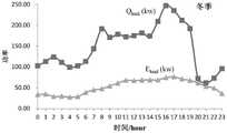
图3是冬季工况的逐时电负荷和等效逐时热需求。Figure 3 shows the hourly electrical load and equivalent hourly heat demand in winter conditions.
图4为夏季工况的电能分配图。Figure 4 is the distribution diagram of electric energy in summer working conditions.
图5为冬季工况的电能分配图。Figure 5 is the distribution diagram of electric energy in winter conditions.
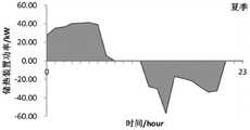
图6为夏季工况的储热装置控制图。Figure 6 is the control diagram of the heat storage device in summer working conditions.
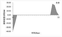
图7为冬季工况的储热装置控制图。Figure 7 is a control diagram of the heat storage device in winter conditions.
具体实施方式detailed description
实施例Example
以下结合附图和具体实施方式对本发明的技术方案做进一步的说明。The technical solutions of the present invention will be further described below in conjunction with the drawings and specific embodiments.
如图1所示,一种含储热装置的分布式系统的能量管理方法,该分布式系统包括燃气机组10、余热回收装置20、燃气锅炉30、吸收式制冷机40、热交换器50、储热装置60。燃气机组10连接燃气管网100获取天然气、产生电能并由余热回收装置20将余热进行回收;燃气锅炉30连接燃气管网100获取天然气,产生热能。燃气机组10和电网200提供电能满足用户电负荷需求;余热回收装置20和燃气锅炉30提供热能,且通过吸收式制冷机40转换为合适的冷能满足用户冷负荷需求、通过热交换器50转换为合适的热能满足用户热负荷需求。通过储热装置60的存储释放实现系统热能的调节。As shown in Figure 1, an energy management method for a distributed system including a heat storage device, the distributed system includes a gas-fired
实施对象包括夏季和冬季两种典型用户工况,图2和图3分别为夏季工况和冬季工况对应的逐时电负荷和等效逐时热需求。其中,等效逐时热需求根据用户的冷负荷和热负荷,结合吸收式制冷机的COP和热交换器的效率计算得到,本实施例中,吸收式制冷机的COP为1.2,热交换器的效率为0.9。The implementation objects include two typical user working conditions in summer and winter. Figure 2 and Figure 3 show the hourly electric load and equivalent hourly heat demand corresponding to the summer working condition and winter working condition respectively. Among them, the equivalent hourly heat demand is calculated according to the cooling load and heating load of the user, combined with the COP of the absorption chiller and the efficiency of the heat exchanger. In this embodiment, the COP of the absorption chiller is 1.2, and the heat exchanger The efficiency is 0.9.
实施对象的燃气机组为内燃机,额定功率67kw,其电效率和热效率可通过美国采暖、制冷与空调工程师学会制定的自然吸气式小型机组标准特性数据拟合得到。The gas-fired unit to be implemented is an internal combustion engine with a rated power of 67kw. Its electrical efficiency and thermal efficiency can be obtained by fitting the standard characteristic data of naturally aspirated small units formulated by the American Society of Heating, Refrigerating and Air-Conditioning Engineers.
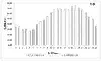
根据电能分配的步骤,将24个小时的逐时电负荷Eload(t)与燃气机组额定功率值67kw做比较,得到的燃气机组逐时输出电功率:当Eload(t)>67,燃气机组输出电功率为67kw,不足部分由电网提供;如夏季工况t=10的时段,Eload(10)=82.59kW,则燃气机组以额定状态运行,输出功率为67kW,此时电网向用户提供电能为15.59kW。当Eload(t)≤67,燃气机组输出电功率为Ecchp(t)=Eload(t),电网不提供电能;如夏季t=5的时段,Eload(5)=40.42kW,则燃气机组输出功率为40.42kW,此时电网不提供电能。图4和图5分别为夏季工况和冬季工况对应的电能分配方法。According to the steps of electric energy distribution, compare the 24-hour hourly electric load Eload (t) with the rated power value of the gas unit 67kw, and obtain the hourly output electric power of the gas unit: when Eload (t) > 67, the gas unit The output electric power is 67kw, and the insufficient part is provided by the power grid; for example, during the period of summer working condition t=10, Eload (10)=82.59kW, the gas-fired unit operates at the rated state, and the output power is 67kW. At this time, the power grid provides electric energy to the user It is 15.59kW. When Eload (t)≤67 , the output electric power of the gas-fired unit is Ecchp (t)=Eload (t), and the grid does not provide electric energy; The output power of the unit is 40.42kW, and the grid does not provide electric energy at this time. Figure 4 and Figure 5 respectively show the power distribution methods corresponding to summer and winter conditions.
根据上述得到的逐时Ecchp(t)以及
该分布式系统的储热装置容量设计如下:分别计算夏季工况和冬季工况24个时段回收热能Qre(t)与用户热需求Qload(t)的差值得到逐时热差值Qdiff(t)。分别将夏季工况和冬季工况全部时段的Qdiff(t)求和得到总和QTdiff,可知夏季工况QTdiff=292.27kWh,冬季工况QTdiff=-1430.68kWh。若QTdiff>0,则将Qdiff(t)小于0的时段进行求和得到不足时段的总和Qinsuf,并取绝对值作为预选容量值;如夏季工况大于0,计算得到不足时段的总和为-266kWh,则将266kWh作为预选容量值。若QTdiff<0,则将Qdiff(t)大于0的时段进行求和得到富余时段的总和Qsurplus,并取绝对值作为预选容量值;如冬季工况小于0,计算得到富余时段的总和为57kWh,则将57kWh作为预选容量值。比较所有的预选容量值,其中的最大值即作为储热装置的设计容量,则该储热装置设计容量为266kWh。The heat storage device capacity design of the distributed system is as follows: Calculate the difference between the recovered heat energy Qre (t) and the user’s heat demand Qload (t) in 24 periods of summer and winter conditions respectively to obtain the hourly heat difference Qdiff (t). The total QTdiff is obtained by summing the Qdiff (t) in all periods of the summer and winter conditions respectively. It can be known that the summer condition QTdiff =292.27kWh, and the winter condition QTdiff =-1430.68kWh. If QTdiff > 0, then sum the periods of Qdiff (t) less than 0 to obtain the sum Qinsuf of the insufficient period, and take the absolute value as the pre-selected capacity value; if the summer operating condition is greater than 0, calculate the sum of the insufficient period If it is -266kWh, then 266kWh will be used as the pre-selected capacity value. If QTdiff < 0, then sum the periods of Qdiff (t) greater than 0 to obtain the sum Qsurplus of the surplus period, and take the absolute value as the pre-selected capacity value; if the winter condition is less than 0, calculate the sum of the surplus period is 57kWh, then 57kWh will be used as the pre-selected capacity value. Comparing all the pre-selected capacity values, the maximum value is taken as the design capacity of the heat storage device, then the design capacity of the heat storage device is 266kWh.
根据上述余热回收装置向用户提供的热能以及储热装置设计容量,采用以下方法设计储热装置的储能和释能控制方法:According to the heat energy provided by the above-mentioned waste heat recovery device to the user and the design capacity of the heat storage device, the following methods are used to design the energy storage and energy release control method of the heat storage device:
在储能阶段,选取所有Qdiff(t)大于0的时段、按时间顺序进行排序,并根据以下原则确定储热装置的储能功率:取逐时热差值Qdiff(t)、储热装置最大功率Qmax_TESS、储热装置未存满容量CTESS-CTESS(t)三个参数中绝对值的最小值作为储能装置实时功率QTESS(t),将回收热能的富余部分存储到储热装置中;若仍有多余,则多余部分热能释放到周围环境中。如夏季工况t=0时段,Qdiff(0)=27.5,Qmax_TESS=66.5,CTESS-CTESS(0)=266,则QTESS(0)=27.5kW,储热装置存储的热能总和为Qsto=27.5kWh;又如夏季工况t=7时段,Qdiff(7)=45.49,Qmax_TESS=66.5,CTESS-CTESS(7)=5.31,则QTESS(7)=5.31kW,储热装置存储的热能总和为Qsto=266kWh。In the energy storage stage, select all time periods with Qdiff (t) greater than 0, sort them in time order, and determine the energy storage power of the heat storage device according to the following principles: take the hourly heat difference Qdiff (t), heat storage The minimum value of the absolute value among the three parameters of the maximum power Qmax_TESS of the device and the unfulfilled capacity of the heat storage device CTESS -CTESS (t) is used as the real-time power QTESS (t) of the energy storage device, and the surplus part of the recovered heat energy is stored in In the heat storage device; if there is still excess, the excess heat energy is released to the surrounding environment. For example, during summer working condition t=0, Qdiff (0)=27.5, Qmax_TESS =66.5, CTESS -CTESS (0)=266, then QTESS (0)=27.5kW, the total heat energy stored by the heat storage device Qsto =27.5kWh; for another example in summer working condition t=7 period, Qdiff (7)=45.49, Qmax_TESS =66.5, CTESS -CTESS (7)=5.31, then QTESS (7)=5.31kW , the total heat energy stored by the heat storage device is Qsto =266kWh.
在释能阶段,选取所有Qdiff(t)小于0的时段、按时间顺序进行排序,并根据以下原则确定储热装置的释能功率:取逐时热差值Qdiff(t)、储热装置最大功率Qmax_TESS、储热装置当前容量CTESS(t)三个参数中绝对值的最小值、取相反数作为储能装置实时功率QTESS(t),将储热装置中存储的热能进行释放以提供用户热能需求;若仍然不足,则不足部分热能由燃气锅炉提供。如夏季工况t=12时段,Qdiff(12)=-17.66,Qmax_TESS=66.5,CTESS(12)=266,则QTESS(12)=-27.66kW,储热装置释放的热能总和为Qrel=27.66kWh;又如冬季工况t=19时段,Qdiff(19)=-80.49,Qmax_TESS=66.5,CTESS(19)=0,则QTESS(19)=0kW,储热装置释放的热能总和为Qrel=57.11kWh。In the energy release stage, select all time periods with Qdiff (t) less than 0, sort them in chronological order, and determine the energy release power of the heat storage device according to the following principles: take the hourly heat difference Qdiff (t), heat storage The maximum power Qmax_TESS of the device, the minimum absolute value of the three parameters of the current capacity CTESS (t) of the heat storage device, and the opposite number is taken as the real-time power QTESS (t) of the energy storage device, and the thermal energy stored in the heat storage device is Released to meet the user's heat energy demand; if it is still insufficient, the insufficient heat energy will be provided by the gas boiler. For example, in the summer working condition t=12 period, Qdiff (12)=-17.66, Qmax_TESS =66.5, CTESS (12)=266, then QTESS (12)=-27.66kW, the total heat energy released by the heat storage device is Qrel =27.66kWh; another example is the winter working condition t=19 period, Qdiff (19)=-80.49, Qmax_TESS =66.5, CTESS (19)=0, then QTESS (19)=0kW, heat storage device The sum of released thermal energy is Qrel =57.11 kWh.
在储热装置存储和释放平衡校验阶段,比较Qsto与Qrel的大小,若Qsto>Qrel,选取所有Qdiff(t)大于0的时段、按时间倒序进行排序,逐时减少储热装置存储的储热功率、并同步减少存储的热能总和Qsto,直至Qsto=Qrel时跳出该步骤。In the storage and release balance verification stage of the heat storage device, compare the sizes of Qsto and Qrel . If Qsto > Qrel , select all periods when Qdiff (t) is greater than 0, sort them in reverse order of time, and reduce the storage time by time. The heat storage power stored by the thermal device, and the sum of stored heat energy Qsto is reduced synchronously until Qsto =Qrel and this step is skipped.
根据上述步骤,可以得到储热装置的控制方法,图6和图7分别为夏季工况和冬季工况对应的储热装置控制方法。则在Qdiff(t)<0时段,燃气锅炉的功率可由QGB(t)=|Qdiff(t)-QTESS(t)|得到;如冬季工况t=19时段,燃气锅炉提供的热能为QGB(19)=80.49kW。在Qdiff(t)>0时段,释放到周围环境中的损失热能可由Qloss(t)=Qdiff(t)-QTESS(t)得到;如夏季工况t=7时段,系统有40.18kWh的多余热能释放到了周围环境中。According to the above steps, the control method of the heat storage device can be obtained, and Fig. 6 and Fig. 7 respectively show the control methods of the heat storage device corresponding to the summer working condition and the winter working condition. Then in the period of Qdiff (t)<0, the power of the gas boiler can be obtained by QGB (t)=|Qdiff (t)-QTESS (t)| The heat energy is QGB (19) = 80.49kW. In the period of Qdiff (t) > 0, the loss heat energy released to the surrounding environment can be obtained by Qloss (t) = Qdiff (t) - QTESS (t); for example, in the summer operating condition t = 7 period, the system has 40.18 kWh of excess heat energy is released into the surrounding environment.
上列详细说明是针对本发明可行实施例的具体说明,该实施例并非用以限制本发明的专利范围,凡未脱离本发明所为的等效实施或变更,均应包含于本案的专利范围中。The above detailed description is a specific description of the feasible embodiment of the present invention. This embodiment is not used to limit the patent scope of the present invention. Any equivalent implementation or change that does not deviate from the present invention should be included in the patent scope of this case. middle.
Claims (3)
Translated fromChinese


Priority Applications (1)
| Application Number | Priority Date | Filing Date | Title |
|---|---|---|---|
| CN201910703793.6ACN110570010B (en) | 2019-07-31 | 2019-07-31 | An energy management method for a distributed system with a heat storage device |
Applications Claiming Priority (1)
| Application Number | Priority Date | Filing Date | Title |
|---|---|---|---|
| CN201910703793.6ACN110570010B (en) | 2019-07-31 | 2019-07-31 | An energy management method for a distributed system with a heat storage device |
Publications (2)
| Publication Number | Publication Date |
|---|---|
| CN110570010A CN110570010A (en) | 2019-12-13 |
| CN110570010Btrue CN110570010B (en) | 2023-01-17 |
Family
ID=68773877
Family Applications (1)
| Application Number | Title | Priority Date | Filing Date |
|---|---|---|---|
| CN201910703793.6AActiveCN110570010B (en) | 2019-07-31 | 2019-07-31 | An energy management method for a distributed system with a heat storage device |
Country Status (1)
| Country | Link |
|---|---|
| CN (1) | CN110570010B (en) |
Families Citing this family (2)
| Publication number | Priority date | Publication date | Assignee | Title |
|---|---|---|---|---|
| CN112325687B (en)* | 2020-10-28 | 2022-10-25 | 广东电网有限责任公司广州供电局 | Multi-energy complementary distributed energy system with cross-season heat storage function |
| CN112528210B (en)* | 2020-12-07 | 2023-06-13 | 中国科学院广州能源研究所 | Combined cooling heating and power system and control method |
Citations (7)
| Publication number | Priority date | Publication date | Assignee | Title |
|---|---|---|---|---|
| CN102436602A (en)* | 2010-08-31 | 2012-05-02 | 株式会社日立制作所 | Energy management system and energy management method |
| CN105610846A (en)* | 2016-01-08 | 2016-05-25 | 辽宁北方节能股份有限公司 | System for managing electrical energy monitoring terminal data acquisition energy consumption and application method thereof |
| CN107609684A (en)* | 2017-08-24 | 2018-01-19 | 浙江万克新能源科技有限公司 | A kind of integrated energy system economic optimization dispatching method based on micro-capacitance sensor |
| CN108206543A (en)* | 2018-02-05 | 2018-06-26 | 东北大学 | A kind of energy source router and its running optimizatin method based on energy cascade utilization |
| CN108805452A (en)* | 2018-06-12 | 2018-11-13 | 湖北仁威电业科技有限公司 | A kind of electric energy management system based on technology of Internet of things |
| CN109118293A (en)* | 2018-08-31 | 2019-01-01 | 东南大学 | A kind of thermo-electrically integrated energy source management system and method |
| CN109919478A (en)* | 2019-02-28 | 2019-06-21 | 天津大学 | A comprehensive energy microgrid planning method considering the reliability of comprehensive energy supply |
Family Cites Families (3)
| Publication number | Priority date | Publication date | Assignee | Title |
|---|---|---|---|---|
| US9865024B2 (en)* | 2013-03-15 | 2018-01-09 | Open Access Technology International, Inc. | Systems and methods of determining optimal scheduling and dispatch of power resources |
| CA2847058A1 (en)* | 2013-03-15 | 2014-09-15 | Open Access Technology Intenrational, Inc. | Systems and methods for managing energy generation and procurement |
| US20180005326A1 (en)* | 2016-06-30 | 2018-01-04 | Ryan Allan Reid | Electric Radiator Using Calculating Processors as a Heat Source |
- 2019
- 2019-07-31CNCN201910703793.6Apatent/CN110570010B/enactiveActive
Patent Citations (7)
| Publication number | Priority date | Publication date | Assignee | Title |
|---|---|---|---|---|
| CN102436602A (en)* | 2010-08-31 | 2012-05-02 | 株式会社日立制作所 | Energy management system and energy management method |
| CN105610846A (en)* | 2016-01-08 | 2016-05-25 | 辽宁北方节能股份有限公司 | System for managing electrical energy monitoring terminal data acquisition energy consumption and application method thereof |
| CN107609684A (en)* | 2017-08-24 | 2018-01-19 | 浙江万克新能源科技有限公司 | A kind of integrated energy system economic optimization dispatching method based on micro-capacitance sensor |
| CN108206543A (en)* | 2018-02-05 | 2018-06-26 | 东北大学 | A kind of energy source router and its running optimizatin method based on energy cascade utilization |
| CN108805452A (en)* | 2018-06-12 | 2018-11-13 | 湖北仁威电业科技有限公司 | A kind of electric energy management system based on technology of Internet of things |
| CN109118293A (en)* | 2018-08-31 | 2019-01-01 | 东南大学 | A kind of thermo-electrically integrated energy source management system and method |
| CN109919478A (en)* | 2019-02-28 | 2019-06-21 | 天津大学 | A comprehensive energy microgrid planning method considering the reliability of comprehensive energy supply |
Non-Patent Citations (1)
| Title |
|---|
| 储能技术在太阳能分布式冷热电联供中的应用;杨昌儒 等;《新能源进展》;20170430;第5卷(第2期);第127页-第135页* |
Also Published As
| Publication number | Publication date |
|---|---|
| CN110570010A (en) | 2019-12-13 |
Similar Documents
| Publication | Publication Date | Title |
|---|---|---|
| CN108717594B (en) | An economic optimal scheduling method for a combined cooling, heating and power multi-microgrid system | |
| CN109696891B (en) | Micro energy network system comprising air source heat pump and energy storage and operation control method thereof | |
| CN111400641B (en) | A day-ahead optimization dispatching method for integrated energy systems with thermal storage electric heating | |
| CN110598313B (en) | Comprehensive energy system optimal configuration method considering energy storage full life cycle operation and maintenance | |
| CN103400042B (en) | The micro-network optimization collocation method of a kind of supply of cooling, heating and electrical powers type | |
| CN112398164B (en) | Optimal operation and cost allocation method of micro-energy network cluster with shared energy storage system | |
| CN108416472A (en) | A kind of Regional And Multi-source cold and heat supply system optimization dispatching method | |
| CN107832979A (en) | A kind of factory integration energy resource system economic optimization dispatching method for considering cascaded utilization of energy | |
| CN108487994B (en) | A kind of micro- energy net composite energy storage system | |
| WO2019205561A1 (en) | Cchp micro-grid structure including compressed air energy storage and operation method therefor | |
| CN112600253B (en) | Synergistic optimization method and equipment for park comprehensive energy based on optimal energy efficiency | |
| CN103257571A (en) | Air conditioning load control strategy making method based on direct load control | |
| CN104730923A (en) | Combined cooling-heating-power based comprehensive energy optimizing and controlling method for smart power grid region | |
| Li et al. | Optimal design of installation capacity and operation strategy for distributed energy system | |
| CN108133285A (en) | A kind of energy mix system real-time scheduling method for accessing extensive regenerative resource | |
| CN108808663A (en) | It is a kind of based on the industrial user's heat demand response method provided multiple forms of energy to complement each other | |
| CN110570010B (en) | An energy management method for a distributed system with a heat storage device | |
| CN115688448A (en) | An optimal scheduling method for multi-regional integrated energy systems considering shared energy storage | |
| CN116911437A (en) | An optimal scheduling method for data center energy systems considering load response characteristics | |
| CN107546747A (en) | A kind of automatic demand response operational mode based on flexible load control | |
| CN113807746B (en) | Comprehensive operation optimization method of combined cooling heating power system | |
| CN114330835A (en) | Optimal configuration method of electricity/heat hybrid energy storage system in comprehensive energy microgrid | |
| CN111125611B (en) | Multi-scene-oriented cold-hot-electric micro-energy network group two-stage optimization scheduling method | |
| CN111049134B (en) | A calculation method for multi-energy complementary parks to respond to peak shaving demands of power systems | |
| CN106709178A (en) | Cool-heat-electricity cogeneration microgrid system modeling method |
Legal Events
| Date | Code | Title | Description |
|---|---|---|---|
| PB01 | Publication | ||
| PB01 | Publication | ||
| SE01 | Entry into force of request for substantive examination | ||
| SE01 | Entry into force of request for substantive examination | ||
| GR01 | Patent grant | ||
| GR01 | Patent grant |