CN110537868B - Electric vacuum cleaner system - Google Patents
Electric vacuum cleaner systemDownload PDFInfo
- Publication number
- CN110537868B CN110537868BCN201910386533.0ACN201910386533ACN110537868BCN 110537868 BCN110537868 BCN 110537868BCN 201910386533 ACN201910386533 ACN 201910386533ACN 110537868 BCN110537868 BCN 110537868B
- Authority
- CN
- China
- Prior art keywords
- vacuum cleaner
- adapter
- exhaust port
- electric vacuum
- central axis
- Prior art date
- Legal status (The legal status is an assumption and is not a legal conclusion. Google has not performed a legal analysis and makes no representation as to the accuracy of the status listed.)
- Expired - Fee Related
Links
Images


Classifications
- A—HUMAN NECESSITIES
- A47—FURNITURE; DOMESTIC ARTICLES OR APPLIANCES; COFFEE MILLS; SPICE MILLS; SUCTION CLEANERS IN GENERAL
- A47L—DOMESTIC WASHING OR CLEANING; SUCTION CLEANERS IN GENERAL
- A47L5/00—Structural features of suction cleaners
- A47L5/02—Structural features of suction cleaners with user-driven air-pumps or compressors
- A—HUMAN NECESSITIES
- A47—FURNITURE; DOMESTIC ARTICLES OR APPLIANCES; COFFEE MILLS; SPICE MILLS; SUCTION CLEANERS IN GENERAL
- A47L—DOMESTIC WASHING OR CLEANING; SUCTION CLEANERS IN GENERAL
- A47L9/00—Details or accessories of suction cleaners, e.g. mechanical means for controlling the suction or for effecting pulsating action; Storing devices specially adapted to suction cleaners or parts thereof; Carrying-vehicles specially adapted for suction cleaners
- A47L9/10—Filters; Dust separators; Dust removal; Automatic exchange of filters
- A47L9/16—Arrangement or disposition of cyclones or other devices with centrifugal action
- A47L9/1658—Construction of outlets
- A—HUMAN NECESSITIES
- A47—FURNITURE; DOMESTIC ARTICLES OR APPLIANCES; COFFEE MILLS; SPICE MILLS; SUCTION CLEANERS IN GENERAL
- A47L—DOMESTIC WASHING OR CLEANING; SUCTION CLEANERS IN GENERAL
- A47L9/00—Details or accessories of suction cleaners, e.g. mechanical means for controlling the suction or for effecting pulsating action; Storing devices specially adapted to suction cleaners or parts thereof; Carrying-vehicles specially adapted for suction cleaners
- A47L9/28—Installation of the electric equipment, e.g. adaptation or attachment to the suction cleaner; Controlling suction cleaners by electric means
- A47L9/2836—Installation of the electric equipment, e.g. adaptation or attachment to the suction cleaner; Controlling suction cleaners by electric means characterised by the parts which are controlled
Landscapes
- Engineering & Computer Science (AREA)
- Mechanical Engineering (AREA)
- Electric Suction Cleaners (AREA)
Abstract
Description
Translated fromChinese技术领域technical field
本发明涉及能够利用吸尘器的排气将尘埃吹除的电动吸尘器系统。The present invention relates to an electric vacuum cleaner system capable of blowing off dust by the exhaust gas of the vacuum cleaner.
背景技术Background technique
以往,作为这种电动吸尘器系统,已知有如下的电动吸尘器系统:将适配器安装于具有把持部的吸尘器主体的排气口,并将附件连接于该适配器(例如参照专利文献1。)。并且,所述适配器具有作为宽部的安装部和作为窄部的承接筒部。此外,所述安装部和承接筒部为同轴状。另外,作为安装于所述适配器的承接筒部的附件,使用不具有弯曲性的延长管、能够弯曲的延长软管。Conventionally, as such a vacuum cleaner system, there is known a vacuum cleaner system in which an adapter is attached to an exhaust port of a cleaner body having a grip portion, and an accessory is connected to the adapter (for example, refer to Patent Document 1). Also, the adapter has a mounting portion as a wide portion and a receiving cylindrical portion as a narrow portion. In addition, the attachment portion and the receiving cylindrical portion are coaxial. Moreover, as an attachment to the receiving cylinder part of the said adapter, the extension tube which does not have bendability, and the extension hose which can be bent are used.
在先技术文献prior art literature
专利文献Patent Literature
专利文献1:日本特开2016-49141号公报Patent Document 1: Japanese Patent Laid-Open No. 2016-49141
然而,在这样的适配器中,在使用延长管作为附件或不将附件连接地使用的情况下,会从位于远离所述把持部的位置的承接筒部强力地喷出排气,因此,由于该排气的反作用力,存在操作变得不稳定的可能性。However, in such an adapter, when the extension tube is used as an accessory or when the accessory is used without connecting the accessory, the exhaust gas is strongly ejected from the receiving cylindrical portion located away from the grip portion. Therefore, due to this There is a possibility that the operation may become unstable due to the reaction force of the exhaust gas.
发明内容SUMMARY OF THE INVENTION
本发明是为了解决以上问题而做出的,其目的在于提供能够抑制由排气的喷出气流引起的反作用力并稳定地进行操作的电动吸尘器系统。The present invention has been made to solve the above problems, and an object of the present invention is to provide a vacuum cleaner system that can operate stably while suppressing the reaction force caused by the jet flow of exhaust gas.
本发明的技术方案1记载的电动吸尘器系统具有:电动吸尘器,所述电动吸尘器具有把持部及排气口部;排气利用适配器,所述排气利用适配器具有流通面积相对较大的入口部和流通面积相对较小的出口部;以及排气附件,其中,所述适配器的入口部连接于所述电动吸尘器的排气口部,所述附件连接于所述适配器的出口部,并且,在将所述适配器安装于所述排气口部的状态下,所述出口部的第二中心被设置成相对于所述入口部的第一中心向所述把持部侧偏心。The vacuum cleaner system according to claim 1 of the present invention includes a vacuum cleaner having a grip portion and an exhaust port portion, and an exhaust gas use adapter having an inlet portion having a relatively large flow area and an exhaust port portion. an outlet portion with a relatively small flow area; and an exhaust accessory, wherein the inlet portion of the adapter is connected to the outlet portion of the electric vacuum cleaner, the accessory is connected to the outlet portion of the adapter, and, In a state where the adapter is attached to the exhaust port portion, the second center of the outlet portion is provided eccentrically toward the grip portion side with respect to the first center of the inlet portion.
另外,在技术方案1的基础上,在本发明的技术方案2记载的电动吸尘器系统中,在所述电动吸尘器的排气口部和所述适配器的入口部中的任一方形成有多个用于结合的卡合凹部,在另一方形成有多个用于结合的卡合凸部,并且,所述卡合凹部和卡合凸部以非等间隔的方式设置。In addition to claim 1, in the vacuum cleaner system according to
而且,在技术方案1或2的基础上,在本发明的技术方案3记载的电动吸尘器系统中,所述电动吸尘器具有电源线,并且,在将所述适配器安装于所述排气口部的状态下,所述出口部被设置成偏向与电源线侧相反的一侧。In addition to claim 1 or
本发明的技术方案1记载的电动吸尘器系统通过如以上那样构成,从而能够将基于排气的喷出气流的喷出位置设为所述把持部的附近,因此,在利用喷出气流时,能够抑制由该喷出气流引起的反作用力并稳定地进行操作。The vacuum cleaner system according to claim 1 of the present invention is configured as described above, so that the ejection position of the ejected airflow by the exhaust gas can be set in the vicinity of the grip portion, and therefore, when the ejected airflow is used, it is possible to The reaction force caused by the jetted air flow is suppressed and the operation is stably performed.
此外,在所述电动吸尘器的排气口部和所述适配器的入口部中的任一方形成有多个用于结合的卡合凹部,在另一方形成有多个用于结合的卡合凸部,并且,所述卡合凹部和卡合凸部以非等间隔的方式设置,由此,能够在使所述出口部可靠地偏向所述把持部侧的状态下将所述适配器安装于所述排气口部。In addition, a plurality of engaging concave portions for coupling are formed on one of the exhaust port portion of the vacuum cleaner and the inlet portion of the adapter, and a plurality of engaging convex portions for coupling are formed on the other side. , and the engaging concave portion and the engaging protruding portion are provided at unequal intervals, whereby the adapter can be attached to the adapter in a state where the outlet portion is reliably biased toward the grip portion side. exhaust port.
另外,所述电动吸尘器具有电源线,并且,在将所述适配器安装于所述排气口部的状态下,所述出口部被设置成偏向与电源线侧相反的一侧,由此,所述电源线难以与所述附件缠绕,能够容易地进行操作。In addition, the vacuum cleaner has a power cord, and in a state where the adapter is attached to the exhaust port portion, the outlet portion is provided so as to be offset to the side opposite to the power cord side, so that the The power cord is difficult to be tangled with the accessory, and can be easily handled.
附图说明Description of drawings
图1是表示本发明的一实施方式的电动吸尘器的侧视图。Fig. 1 is a side view showing an electric vacuum cleaner according to an embodiment of the present invention.
图2是表示本发明的一实施方式的外壳壳体与电动送风机的位置关系的说明图。FIG. 2 is an explanatory diagram showing the positional relationship between the housing case and the electric blower according to the embodiment of the present invention.
图3是本发明的一实施方式的外壳壳体的台阶部的放大图。FIG. 3 is an enlarged view of a stepped portion of the housing case according to the embodiment of the present invention.
图4是表示本发明的一实施方式的不使用时的设置状态的侧视图。4 is a side view showing an installation state when not in use according to the embodiment of the present invention.
图5是表示本发明的一实施方式的不使用时的另一设置状态的侧视图。5 is a side view showing another installation state when not in use according to the embodiment of the present invention.
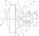
图6是本发明的一实施方式的从与中心轴线正交的方向观察的电动送风机的外观图。6 : is an external view of the electric blower seen from the direction orthogonal to the center axis line concerning one Embodiment of this invention.
图7是本发明的一实施方式的从与中心轴线正交的另一方向观察的电动送风机的外观图。7 is an external view of the electric blower viewed from another direction orthogonal to the central axis according to the embodiment of the present invention.
图8是本发明的一实施方式的将排气利用适配器及排气附件安装于电动吸尘器的电动吸尘器系统的侧视图。8 is a side view of the vacuum cleaner system in which the exhaust gas use adapter and the exhaust gas accessory are attached to the vacuum cleaner according to the embodiment of the present invention.
图9是表示本发明的一实施方式的电动吸尘器系统的不使用时的设置状态的侧视图。9 is a side view showing an installation state of the vacuum cleaner system according to the embodiment of the present invention when not in use.
图10是本发明的一实施方式的电动吸尘器的后视图。Fig. 10 is a rear view of the vacuum cleaner according to the embodiment of the present invention.
图11是本发明的一实施方式的适配器的主视图。11 is a front view of the adapter according to the embodiment of the present invention.
附图标记说明Description of reference numerals
1 电动吸尘器系统 2 电动吸尘器 12 把持部 14 排气口部 15 电源线 26 卡合凸部 261 第一卡合凸部 262 第二卡合凸部 263 第三卡合凸部 50 排气利用适配器 51安装部(入口部) 52 承接筒部(出口部) 54 卡合凹部 541 第一卡合凹部 542 第二卡合凹部 543 第三卡合凹部 60 排气附件 61 延长管(排气附件) 62 延长软管(排气附件)X1 第一中心轴线 X2 第二中心轴线1
具体实施方式Detailed ways
以下,基于图1~图11,对本发明的实施方式进行说明。此外,在本实施方式中,将图1及图2中的左侧设为前侧,将右侧设为后侧。另外,将图1及图2中的上下设为以下的说明中的上下。附图标记1为电动吸尘器系统。该电动吸尘器系统1具有电动吸尘器2、排气利用适配器50及排气附件60。Hereinafter, embodiments of the present invention will be described based on FIGS. 1 to 11 . In addition, in the present embodiment, the left side in FIGS. 1 and 2 is referred to as the front side, and the right side is referred to as the rear side. In addition, the upper and lower sides in FIGS. 1 and 2 are referred to as the upper and lower sides in the following description. Reference numeral 1 is an electric vacuum cleaner system. This vacuum cleaner system 1 includes the
所述电动吸尘器2具有吸尘器主体10和集尘容器40。所述吸尘器主体10具有机体部11和把持部12。所述机体部11具有大致圆筒状的外壳壳体13,该外壳壳体13具有直径不同的部分。并且,在所述机体部11的前侧能够装卸地安装有所述集尘容器40。另外,在所述机体部11的后侧设置有排气口部14。而且,所述把持部12设置于所述机体部11的上方。并且,从所述机体部11引出电源线15。而且,在所述机体部11的内部收容有电动送风机30。The
对所述机体部11的外壳壳体13进行详细叙述。如前述那样,所述外壳壳体13形成为具有直径不同的部分的大致圆筒状。具体而言,具有收容后述的离心式风扇32的风扇收容部16、收容后述的电动机31的电动机收容部17、以及设置于风扇收容部16与电动机收容部17之间的台阶部18。此外,所述风扇收容部16与电动机收容部17相比相对较粗。即,所述电动机收容部17与风扇收容部16相比相对较细。并且,所述电动机收容部17设置于所述风扇收容部16的后方。另外,所述风扇收容部16、电动机收容部17和台阶部18以中心轴线Xb为基准而大致同轴状地设置。此外,所述中心轴线Xb与所述电动送风机30的中心轴线Xm一致。另外,在所述风扇收容部16的前方设置有承接所述集尘容器40的承接部19。另外,所述把持部12的后端部与所述电动机收容部17一体连结。而且,所述把持部12的前端部通过连结部20与所述承接部19连结。并且,在所述台阶部18的下部18D设置有腿部21,并且在该腿部21形成有安装孔部22。而且,在该安装孔部22安装有所述电源线15的线套23。该线套23在自然状态下、即在未施加外力的状态下与所述中心轴线Xb及中心轴线Xm平行。The
所述排气口部14具有圆形的排气口24和以包围该排气口24的方式设置的作为接地部的多个(在本实施方式中为三个)腿部25。此外,也可以将上述腿部25设为一个短筒状的腿部。上述腿部25作为整体与所述中心轴线Xb同轴状地设置。并且,卡合凸部26分别沿与所述中心轴线Xb正交的方向突出地设置于上述腿部25的外周面。此外,所述各卡合凸部26以不同的角度间隔设置。第一卡合凹部541与第二卡合凹部542的角度间隔为θ1。第二卡合凹部542与第三卡合凹部543的角度间隔为θ2。第三卡合凹部543与第一卡合凹部541的角度间隔为θ3。(θ1≠θ2、θ2≠θ3、θ3≠θ1、θ1+θ2+θ3=2π)而且,从所述安装孔部22起到所述腿部25的后端为止的中心轴线Xb方向上的距离L1比所述线套23的从所述安装孔部22突出的突出部分的长度L2长。另外,所述腿部25的突出尺寸L3比所述电源线15的粗细尺寸L4长。The
对所述电动送风机30进行详细叙述。该电动送风机30构成为具有电动机31和离心式风扇32。所述电动机31具有定子33、转子34、整流子35及电刷36。此外,在所述电动机31的定子33存在距旋转轴的中心轴线Xm的距离较长的部分A和距中心轴线Xm的距离较短的部分B。例如,所述定子33距中心轴线Xm的尺寸在图6中为W1,在图7中为W2。并且,W1比W2短。另一方面,从与中心轴线Xm正交的所有方向观察,所述离心式风扇32的半径R相同。并且,所述电动送风机30将其离心式风扇32配置在所述外壳壳体13的风扇收容部16的内侧。另外,所述电动送风机30将其电动机31配置在所述外壳壳体13的从台阶部18到电动机收容部17的内侧。此外,所述电动送风机30以使所述部分B成为上下且使所述部分A成为左右的方式收容在所述外壳壳体13内。因此,从成为所述电动机31的定子33的下部的所述部分B起到所述台阶部18的下部18D的内表面为止的距离比从成为所述定子33的右部或左部的所述部分A起到所述台阶部18的右部或左部的内表面为止的距离长。即,在所述台阶部18的下部18D的内侧存在空间上的富余。因此,在所述台阶部18的下部18D的腿部21设置所述安装孔部22,将所述电源线15的线套23固定于该安装孔部22。像这样,通过从所述台阶部18的下部18D引出所述电源线15,所述吸尘器主体10的内部的配线不会与所述电动送风机30干涉,因此,制造容易。另外,能够使所述外壳壳体13小型化。而且,由于在所述吸尘器主体10的内部的配线中不存在不合理性,因此,能够减少在所述吸尘器主体10内产生断线的可能性。The
如前述那样,所述集尘容器40能够装卸地安装于所述吸尘器主体10的承接部19。并且,所述集尘容器40具有容器主体41、连接于该容器主体41的导入路径42、以及收容在所述容器主体41内的未图示的过滤体。此外,在所述导入路径42的下部设置有腿部43。并且,在以使所述电动吸尘器2的下部成为下方的方式放置在地板面F等上时,所述腿部43和腿部21与所述地板面F相接。此时,从所述排气口部14起到地板面F为止的距离L5比所述电源线15的粗细尺寸L4长。即,在以使所述电动吸尘器2的下部成为下方的方式放置在地板面F等上时,所述电源线15不会成为妨碍。As described above, the
所述适配器50能够装卸地安装于所述排气口部14。并且,所述适配器50具有作为流通面积相对较大的入口部的安装部51、作为流通面积相对较小的出口部的承接筒部52及锁定按钮53。在将所述适配器50安装于所述排气口部14时,所述安装部51的第一中心轴线X1与所述外壳壳体13的中心轴线Xb同轴。另一方面,所述承接筒部52的第二中心轴线X2相对于所述第一中心轴线X1偏心。此外,第一中心轴线X1与第二中心轴线X2平行。在所述安装部51的内周面设置有多个卡合凹部54。上述卡合凹部54与所述排气口部14的卡合凸部26对应地设置。即,所述各卡合凹部54以不同的角度间隔设置。例如,第一卡合凹部541与第二卡合凹部542的角度间隔为约127度。第二卡合凹部542与第三卡合凹部543的角度间隔为约102度。第三卡合凹部543与第一卡合凹部541的角度间隔为约131度。因此,仅在所述第一卡合凸部261与第一卡合凹部541卡合、第二卡合凸部262与第二卡合凹部542卡合、第三卡合凸部263与第三卡合凹部543卡合的状态下,将所述适配器50安装于所述排气口部14。在该结合状态下,所述承接筒部52的第二中心轴线X2相对于所述安装部51的第一中心轴线X1及所述外壳壳体13的中心轴线Xb偏向所述把持部12侧即上侧。即,所述承接筒部52的第二中心轴线X2相对于所述安装部51的第一中心轴线X1及所述外壳壳体13的中心轴线Xb偏向与设置有所述电源线15的下侧相反的一侧即上侧。此外,虽然未进行图示,但所述各卡合凹部54为L字状的槽。因此,所述适配器50卡口结合于所述排气口部14。The
所述附件60能够装卸地连接于所述承接筒部52。若详细叙述,则在所述附件60设置有未图示的卡合凹部,通过将设置于所述锁定按钮53的卡合爪55卡合于该卡合凹部,从而将所述附件60连接于所述承接筒部52。此外,所述附件60能够使用图8所示的那样的整体为筒状的延长管61、图9所示的那样的具有软管状的部分的延长软管62。The
接着,对本实施方式的作用进行说明。首先,在仅使用所述电动吸尘器系统1的电动吸尘器2的情况下,使用者预先将所述集尘容器40安装于所述吸尘器主体10的承接部19。然后,将所述电源线15连接于未图示的交流电源,通过把持所述把持部12并使所述电动送风机30工作,从而进行吸引打扫。此外,吸引打扫既可以以从所述导入路径42直接吸引尘埃的方式进行,另外,也可以在将未图示的吸引打扫用附件安装于所述导入路径42的状态下进行。然后,将从所述导入路径42被吸引的气流所包含的尘埃在所述集尘容器40内从气流中分离,并储存在该集尘容器40内。将尘埃分离后的气流经由所述电动送风机30从所述排气口24向所述电动吸尘器2的外部排出。并且,在进行吸引打扫时,使用者把持设置于所述电动吸尘器2的上部的所述把持部12,因此,设置于所述电动吸尘器2的下部的所述电源线15不会成为妨碍。Next, the operation of this embodiment will be described. First, when only the
在不使用时,或在暂时停止吸引打扫而放置所述电动吸尘器2的情况下,存在几种放置方法。作为代表性的例子,有图4所示的那样的使所述吸尘器主体10的腿部21和所述集尘容器40的腿部43与地板面F等相接的放置方法、图5所示的那样的使所述电动吸尘器2的排气口部14的腿部25与地板面F相接的放置方法。在前者的放置方法中,如前述那样,由于从所述排气口部14起到地板面F为止的距离L5比所述电源线15的粗细尺寸L4大,因此,所述电源线15不会成为妨碍。另外,通过将所述电源线15与所述中心轴线Xb平行地引出,即使存在由重力引起的稍许弯曲,所述电源线15也不会在所述线套23部分与地板面F抵接而急剧地弯曲。因此,在所述电源线15不会施加较大的应力。在后者的放置方法中,如前述那样,由于从所述安装孔部22起到所述腿部25后端为止的距离L1比所述线套23的突出部分的长度L2长,因此,即使所述电源线15与地板面F抵接而弯曲,所述线套23部分也不会急剧地弯曲。因此,在所述电源线15不会施加较大的应力。此外,也有可能会产生所述电源线15进入到所述排气口部14的下方的情况。然而,如前述那样,由于所述腿部25的突出尺寸L3比所述电源线15的粗细尺寸L4长,因此,能够减少该电源线15被所述排气口部14和地板面F夹着的可能性。即,即使所述电源线15进入到所述排气口部14的下方,所述电源线15也会通过所述腿部25彼此之间的切口部。特别是,如图10所示,由于所述腿部25彼此之间的切口部位于所述排气口部14的下部,因此,所述电源线15容易通过位于其附近的所述腿部25彼此之间的切口部。像这样,在放置所述电动吸尘器2时,能够使所述电源线15难以破损。There are several ways of placing the
接着,对将所述适配器50及附件60安装于所述电动吸尘器系统1的电动吸尘器2的排气口部14并使用的情况进行说明。此外,如前述那样,所述适配器50卡口结合于所述排气口部14。并且,如前述那样,仅在所述第一卡合凸部261与第一卡合凹部541卡合、第二卡合凸部262与第二卡合凹部542卡合、第三卡合凸部263与第三卡合凹部543卡合的状态下,将所述适配器50安装于所述排气口部14。此时,所述适配器50仅在使其承接筒部52的中心轴线X2相对于所述外壳壳体13的中心轴线Xb偏向所述把持部12侧即上方的状态下被安装。换言之,所述适配器50仅在使其承接筒部52的中心轴线X2相对于所述外壳壳体13的中心轴线Xb偏向与电源线15侧相反的一侧即上侧的状态下被安装。Next, the case where the
在将管状的所述延长管61连接于所述适配器50的承接筒部52并使用的情况下,使用者与进行吸引打扫的情况前后相反地把持所述把持部12。即,使用者以使所述排气口部14成为前侧方式进行把持。当在该状态下使所述电动送风机30工作时,从所述导入路径42被吸引的气流经由所述电动送风机30从所述排气口24向所述电动吸尘器2的外部排出。然后,被排出到所述电动吸尘器2的外部的气流从所述适配器50的安装部51经由承接筒部52从所述延长管61喷出。使用该喷出气流,使用者能够将散乱到地面等上的落叶等尘埃吹除。When the
此时,由于喷出气流,会在使用者的手上产生反作用力。然而,由于所述适配器50的承接筒部52的中心轴线X2相比于所述外壳壳体13的中心轴线Xb偏向所述把持部12侧即使用者的手的那一侧,因此,会在使用者的手的附近承接喷出气流的反作用力。因此,能够抑制喷出气流的反作用力并稳定地操作所述电动吸尘器系统1。此外,在将所述延长软管62连接于所述承接筒部52的情况下,用一只手把持所述把持部12,用另一只手把持所述延长软管62的顶端。在该情况下,另一只手承接由喷出气流引起的反作用力。另外,在将所述延长软管62连接于所述承接筒部52的情况下,使用者可以以任意方式把持所述把持部12。At this time, a reaction force is generated on the user's hand due to the jetted airflow. However, since the central axis X2 of the receiving
另外,如前述那样,由于所述适配器50的承接筒部52的中心轴线X2相比于所述外壳壳体13的中心轴线Xb偏向与电源线15侧相反的一侧,并且,该电源线15位于比所述适配器50靠下方的位置,因此,所述电源线15不会缠绕于所述适配器50、附件60。因此,能够良好地进行使用喷出气流的打扫。In addition, as described above, since the central axis X2 of the receiving
在不使用时,或在暂时停止使用喷出气流的打扫并在安装有所述适配器50、附件60的状态下放置所述电动吸尘器系统1的情况下,如图9所示,以使所述吸尘器主体10的腿部21和所述集尘容器40的腿部43与地板面F等相接的方式进行放置。此外,在将所述延长管61连接于所述承接筒部52的状态下,所述延长管61与地板面F等相接,所述腿部21不与地板面F相接。因此,在该情况下,无法稳定地放置所述电动吸尘器系统1,因此,将所述延长管61或所述适配器50和延长管61这双方从所述排气口部14拆下。另一方面,在将所述延长软管62连接于所述承接筒部52的情况下,软管状的部分62H会如图9所示那样弯曲,因此,能够在安装有所述延长软管62的状态下将所述电动吸尘器系统1放置在地板面F等上。并且,由于所述适配器50的承接筒部52的中心轴线X2相比于所述外壳壳体13的中心轴线Xb偏向上方的相反侧,因此,能够防止所述延长软管62的连接筒部62T与地板面F等相接。由此,能够在连接有所述适配器50及延长软管62的状态下将所述电动吸尘器系统1稳定地放置在地板面F等上。When not in use, or when cleaning using the jet air is temporarily stopped and the vacuum cleaner system 1 is placed with the
如以上那样,本发明的电动吸尘器系统1具有:电动吸尘器2,所述电动吸尘器2具有把持部12及排气口部14;排气利用适配器50,所述排气利用适配器50具有作为流通面积相对较大的入口部的安装部51和作为流通面积相对较小的出口部的承接筒部52;以及排气附件60,其中,所述适配器50的安装部51连接于所述电动吸尘器2的排气口部14,所述附件60连接于所述适配器50的承接筒部52,并且,在将所述适配器50安装于所述排气口部14的状态下,所述承接筒部52的第二中心X2被设置成相对于所述安装部51的第一中心X1向所述把持部12侧偏心,由此,能够将排气的喷出位置设为所述把持部12的附近,因此,在利用喷出气流时,能够抑制由该喷出气流引起的反作用力并稳定地进行操作。As described above, the vacuum cleaner system 1 of the present invention includes the
另外,本发明的电动吸尘器系统1在所述电动吸尘器2的排气口部12形成有多个用于结合的卡合凸部261、262、263,在所述适配器50的安装部51形成有多个用于结合的卡合凹部541、542、543,并且,这些卡合凹部541、542、543和卡合凸部261、262、263以非等间隔的方式设置,由此,能够在使所述承接筒部52可靠地偏向所述把持部12侧的状态下将所述适配器50安装于所述排气口部14。In addition, in the vacuum cleaner system 1 of the present invention, a plurality of engaging
而且,本发明的电动吸尘器系统1的所述电动吸尘器2具有电源线15,并且,在将所述适配器50安装于所述排气口部14的状态下,所述承接筒部52被设置成偏向与电源线15侧相反的一侧,由此,所述电源线15难以与所述附件60缠绕,能够容易地进行操作。Furthermore, the
此外,本发明并不限定于以上的实施方式,能够在发明主旨的范围内以各种变形来实施。例如,在上述实施方式中,将卡合凸部设置于排气口部,将卡合凹部设置于适配器,但也可以将卡合凹部设置于排气口部,将卡合凸部设置于适配器。另外,在上述实施方式中,使第一卡合凸部、第二卡合凸部及第三卡合凸部的角度间隔均不相同,但主要的是,只要能够确定排气口部和适配器的位置关系即可,因此,也可以仅使第一卡合凸部、第二卡合凸部及第三卡合凸部的角度间隔中的一个不同。同样地,使第一卡合凹部、第二卡合凹部及第三卡合凹部的角度间隔均不相同,但也可以仅使第一卡合凹部、第二卡合凹部及第三卡合凹部的角度间隔中的一个不同。而且,承接筒部的第二中心轴线相对于安装部的第一中心轴线的偏心量能够任意地设定。例如,在上述实施方式中,沿着第一中心轴线X1观察的承接筒部位于安装部的轮廓内,但也可以设为使承接筒部位于安装部的轮廓外那样的位置关系。另外,在上述实施方式中,安装部的第一中心轴线与承接筒部的第二中心轴线平行,但也可以使承接筒部相对于安装部倾斜。In addition, this invention is not limited to the above-mentioned embodiment, It can implement in various deformation|transformation in the range of the summary of invention. For example, in the above-described embodiment, the engaging convex portion is provided in the exhaust port portion and the engaging concave portion is provided in the adapter, but the engaging concave portion may be provided in the exhaust port portion, and the engaging convex portion may be provided in the adapter . In addition, in the above-described embodiment, the angular intervals of the first engagement convex portion, the second engagement convex portion, and the third engagement convex portion are all made different, but the main thing is that the exhaust port portion and the adapter can be specified as long as the angular interval is different. Therefore, only one of the angular intervals of the first engagement convex portion, the second engagement convex portion, and the third engagement convex portion may be made different. Similarly, the angular intervals of the first engagement recessed portion, the second engagement recessed portion, and the third engagement recessed portion are all different, but only the first engagement recessed portion, the second engagement recessed portion, and the third engagement recessed portion may be used. one of the angular intervals is different. Furthermore, the amount of eccentricity of the second central axis of the receiving cylindrical portion with respect to the first central axis of the mounting portion can be arbitrarily set. For example, in the above-described embodiment, the receiving cylindrical portion as viewed along the first central axis X1 is located within the contour of the mounting portion, but the positional relationship may be such that the receiving cylindrical portion is located outside the contour of the mounting portion. In addition, in the above-described embodiment, the first central axis of the mounting portion is parallel to the second central axis of the receiving cylindrical portion, but the receiving cylindrical portion may be inclined with respect to the mounting portion.
Claims (3)
Applications Claiming Priority (2)
| Application Number | Priority Date | Filing Date | Title |
|---|---|---|---|
| JP2018-101775 | 2018-05-28 | ||
| JP2018101775AJP7105108B2 (en) | 2018-05-28 | 2018-05-28 | vacuum cleaner system |
Publications (2)
| Publication Number | Publication Date |
|---|---|
| CN110537868A CN110537868A (en) | 2019-12-06 |
| CN110537868Btrue CN110537868B (en) | 2022-04-08 |
Family
ID=68702718
Family Applications (1)
| Application Number | Title | Priority Date | Filing Date |
|---|---|---|---|
| CN201910386533.0AExpired - Fee RelatedCN110537868B (en) | 2018-05-28 | 2019-05-10 | Electric vacuum cleaner system |
Country Status (2)
| Country | Link |
|---|---|
| JP (1) | JP7105108B2 (en) |
| CN (1) | CN110537868B (en) |
Citations (4)
| Publication number | Priority date | Publication date | Assignee | Title |
|---|---|---|---|---|
| CN103154375A (en)* | 2010-09-20 | 2013-06-12 | 佩朗股份有限公司 | Hand-held electric blower |
| CN203476823U (en)* | 2013-07-25 | 2014-03-12 | 南京德朔实业有限公司 | Hand-held hair dryer and fan assembly thereof |
| CN105380560A (en)* | 2014-08-28 | 2016-03-09 | 珍巴多工业股份有限公司 | Electric dust collector |
| CN107708405A (en)* | 2015-05-07 | 2018-02-16 | 布莱克和戴克公司 | Aerofoil fan air blower and vacuum plant |
Family Cites Families (6)
| Publication number | Priority date | Publication date | Assignee | Title |
|---|---|---|---|---|
| JPS5814923Y2 (en)* | 1978-01-31 | 1983-03-25 | 東芝テック株式会社 | Vacuum cleaner exhaust system |
| JPS5759081Y2 (en)* | 1978-04-14 | 1982-12-17 | ||
| US8806705B2 (en)* | 2009-04-10 | 2014-08-19 | John M. Minor | Leaf blower |
| CN106284148B (en)* | 2015-05-11 | 2018-05-11 | 南京德朔实业有限公司 | Hair drier |
| JP6488137B2 (en)* | 2015-01-28 | 2019-03-20 | 日立アプライアンス株式会社 | Electric vacuum cleaner |
| JP2017129055A (en)* | 2016-01-20 | 2017-07-27 | ツインバード工業株式会社 | Blower |
- 2018
- 2018-05-28JPJP2018101775Apatent/JP7105108B2/enactiveActive
- 2019
- 2019-05-10CNCN201910386533.0Apatent/CN110537868B/ennot_activeExpired - Fee Related
Patent Citations (4)
| Publication number | Priority date | Publication date | Assignee | Title |
|---|---|---|---|---|
| CN103154375A (en)* | 2010-09-20 | 2013-06-12 | 佩朗股份有限公司 | Hand-held electric blower |
| CN203476823U (en)* | 2013-07-25 | 2014-03-12 | 南京德朔实业有限公司 | Hand-held hair dryer and fan assembly thereof |
| CN105380560A (en)* | 2014-08-28 | 2016-03-09 | 珍巴多工业股份有限公司 | Electric dust collector |
| CN107708405A (en)* | 2015-05-07 | 2018-02-16 | 布莱克和戴克公司 | Aerofoil fan air blower and vacuum plant |
Also Published As
| Publication number | Publication date |
|---|---|
| JP7105108B2 (en) | 2022-07-22 |
| JP2019205547A (en) | 2019-12-05 |
| CN110537868A (en) | 2019-12-06 |
Similar Documents
| Publication | Publication Date | Title |
|---|---|---|
| CN107184141B (en) | Portable electric vacuum cleaner | |
| US11445876B2 (en) | Cleaner | |
| JP6278129B2 (en) | Vacuum cleaner system | |
| JP6419583B2 (en) | Electric vacuum cleaner | |
| CN104414586A (en) | Vacuum cleaner | |
| JP7549364B2 (en) | Vacuum cleaner extension tube and vacuum cleaner unit | |
| CN105380564A (en) | Vacuum cleaner | |
| CN208463953U (en) | Handheld charging dust collector with power-off protection structure | |
| WO2014174248A1 (en) | A pipe connector for a surface treating appliance | |
| CN110537868B (en) | Electric vacuum cleaner system | |
| JP7105109B2 (en) | vacuum cleaner | |
| JP2016131793A (en) | Vacuum cleaner | |
| CN108430292B (en) | Vacuum cleaners and handles for vacuum cleaners | |
| JP2018015325A (en) | Electric cleaning device | |
| JP6466176B2 (en) | Electric vacuum cleaner | |
| CN111035319B (en) | Shell of sweeping robot and sweeping robot | |
| JP6204126B2 (en) | Electric vacuum cleaner | |
| CN217137877U (en) | Hand-held cleaning device | |
| KR20160045622A (en) | Dust collection device | |
| JP6416632B2 (en) | Electric vacuum cleaner | |
| CN103974651B (en) | Electric vacuum cleaner | |
| JP2021137351A (en) | Vacuum cleaner | |
| JP6416636B2 (en) | Dust collector and vacuum cleaner | |
| CN217013810U (en) | Cleaning equipment and accessory thereof | |
| CN110638365B (en) | electric vacuum cleaner |
Legal Events
| Date | Code | Title | Description |
|---|---|---|---|
| PB01 | Publication | ||
| PB01 | Publication | ||
| SE01 | Entry into force of request for substantive examination | ||
| SE01 | Entry into force of request for substantive examination | ||
| GR01 | Patent grant | ||
| GR01 | Patent grant | ||
| CF01 | Termination of patent right due to non-payment of annual fee | ||
| CF01 | Termination of patent right due to non-payment of annual fee | Granted publication date:20220408 |