CN110536710B - Passive Safety Needle Guard - Google Patents
Passive Safety Needle GuardDownload PDFInfo
- Publication number
- CN110536710B CN110536710BCN201880025835.9ACN201880025835ACN110536710BCN 110536710 BCN110536710 BCN 110536710BCN 201880025835 ACN201880025835 ACN 201880025835ACN 110536710 BCN110536710 BCN 110536710B
- Authority
- CN
- China
- Prior art keywords
- needle
- surrounding housing
- safety shield
- arm
- housing
- Prior art date
- Legal status (The legal status is an assumption and is not a legal conclusion. Google has not performed a legal analysis and makes no representation as to the accuracy of the status listed.)
- Active
Links
Images


Classifications
- A—HUMAN NECESSITIES
- A61—MEDICAL OR VETERINARY SCIENCE; HYGIENE
- A61M—DEVICES FOR INTRODUCING MEDIA INTO, OR ONTO, THE BODY; DEVICES FOR TRANSDUCING BODY MEDIA OR FOR TAKING MEDIA FROM THE BODY; DEVICES FOR PRODUCING OR ENDING SLEEP OR STUPOR
- A61M5/00—Devices for bringing media into the body in a subcutaneous, intra-vascular or intramuscular way; Accessories therefor, e.g. filling or cleaning devices, arm-rests
- A61M5/178—Syringes
- A61M5/31—Details
- A61M5/32—Needles; Details of needles pertaining to their connection with syringe or hub; Accessories for bringing the needle into, or holding the needle on, the body; Devices for protection of needles
- A61M5/3205—Apparatus for removing or disposing of used needles or syringes, e.g. containers; Means for protection against accidental injuries from used needles
- A61M5/321—Means for protection against accidental injuries by used needles
- A61M5/3243—Means for protection against accidental injuries by used needles being axially-extensible, e.g. protective sleeves coaxially slidable on the syringe barrel
- A61M5/3275—Means for protection against accidental injuries by used needles being axially-extensible, e.g. protective sleeves coaxially slidable on the syringe barrel being connected to the needle hub or syringe by radially deflectable members, e.g. longitudinal slats, cords or bands
- A—HUMAN NECESSITIES
- A61—MEDICAL OR VETERINARY SCIENCE; HYGIENE
- A61M—DEVICES FOR INTRODUCING MEDIA INTO, OR ONTO, THE BODY; DEVICES FOR TRANSDUCING BODY MEDIA OR FOR TAKING MEDIA FROM THE BODY; DEVICES FOR PRODUCING OR ENDING SLEEP OR STUPOR
- A61M5/00—Devices for bringing media into the body in a subcutaneous, intra-vascular or intramuscular way; Accessories therefor, e.g. filling or cleaning devices, arm-rests
- A61M5/178—Syringes
- A61M5/31—Details
- A61M5/32—Needles; Details of needles pertaining to their connection with syringe or hub; Accessories for bringing the needle into, or holding the needle on, the body; Devices for protection of needles
- A—HUMAN NECESSITIES
- A61—MEDICAL OR VETERINARY SCIENCE; HYGIENE
- A61M—DEVICES FOR INTRODUCING MEDIA INTO, OR ONTO, THE BODY; DEVICES FOR TRANSDUCING BODY MEDIA OR FOR TAKING MEDIA FROM THE BODY; DEVICES FOR PRODUCING OR ENDING SLEEP OR STUPOR
- A61M5/00—Devices for bringing media into the body in a subcutaneous, intra-vascular or intramuscular way; Accessories therefor, e.g. filling or cleaning devices, arm-rests
- A61M5/50—Devices for bringing media into the body in a subcutaneous, intra-vascular or intramuscular way; Accessories therefor, e.g. filling or cleaning devices, arm-rests having means for preventing re-use, or for indicating if defective, used, tampered with or unsterile
- A—HUMAN NECESSITIES
- A61—MEDICAL OR VETERINARY SCIENCE; HYGIENE
- A61M—DEVICES FOR INTRODUCING MEDIA INTO, OR ONTO, THE BODY; DEVICES FOR TRANSDUCING BODY MEDIA OR FOR TAKING MEDIA FROM THE BODY; DEVICES FOR PRODUCING OR ENDING SLEEP OR STUPOR
- A61M5/00—Devices for bringing media into the body in a subcutaneous, intra-vascular or intramuscular way; Accessories therefor, e.g. filling or cleaning devices, arm-rests
- A61M5/178—Syringes
- A61M5/31—Details
- A61M5/32—Needles; Details of needles pertaining to their connection with syringe or hub; Accessories for bringing the needle into, or holding the needle on, the body; Devices for protection of needles
- A61M5/3205—Apparatus for removing or disposing of used needles or syringes, e.g. containers; Means for protection against accidental injuries from used needles
- A61M5/321—Means for protection against accidental injuries by used needles
- A61M5/3243—Means for protection against accidental injuries by used needles being axially-extensible, e.g. protective sleeves coaxially slidable on the syringe barrel
- A61M5/3245—Constructional features thereof, e.g. to improve manipulation or functioning
- A61M2005/3247—Means to impede repositioning of protection sleeve from needle covering to needle uncovering position
- A61M2005/3249—Means to disalign the needle tip and the distal needle passage of a needle protection sleeve
- A—HUMAN NECESSITIES
- A61—MEDICAL OR VETERINARY SCIENCE; HYGIENE
- A61M—DEVICES FOR INTRODUCING MEDIA INTO, OR ONTO, THE BODY; DEVICES FOR TRANSDUCING BODY MEDIA OR FOR TAKING MEDIA FROM THE BODY; DEVICES FOR PRODUCING OR ENDING SLEEP OR STUPOR
- A61M5/00—Devices for bringing media into the body in a subcutaneous, intra-vascular or intramuscular way; Accessories therefor, e.g. filling or cleaning devices, arm-rests
- A61M5/178—Syringes
- A61M5/31—Details
- A61M5/32—Needles; Details of needles pertaining to their connection with syringe or hub; Accessories for bringing the needle into, or holding the needle on, the body; Devices for protection of needles
- A61M5/3205—Apparatus for removing or disposing of used needles or syringes, e.g. containers; Means for protection against accidental injuries from used needles
- A61M5/321—Means for protection against accidental injuries by used needles
- A61M5/3243—Means for protection against accidental injuries by used needles being axially-extensible, e.g. protective sleeves coaxially slidable on the syringe barrel
- A61M5/326—Fully automatic sleeve extension, i.e. in which triggering of the sleeve does not require a deliberate action by the user
- A61M2005/3267—Biased sleeves where the needle is uncovered by insertion of the needle into a patient's body
Landscapes
- Health & Medical Sciences (AREA)
- Engineering & Computer Science (AREA)
- Heart & Thoracic Surgery (AREA)
- Vascular Medicine (AREA)
- Anesthesiology (AREA)
- Biomedical Technology (AREA)
- Hematology (AREA)
- Life Sciences & Earth Sciences (AREA)
- Animal Behavior & Ethology (AREA)
- General Health & Medical Sciences (AREA)
- Public Health (AREA)
- Veterinary Medicine (AREA)
- Environmental & Geological Engineering (AREA)
- Infusion, Injection, And Reservoir Apparatuses (AREA)
Abstract
Translated fromChinese
Description
Translated fromChinese优先权要求priority claim
本PCT申请根据35U.S.C§119(e)要求2017年4月20日提交的美国临时申请号62/488,006的权益,其全部内容通过引用并入本文。This PCT application claims the benefit of US Provisional Application No. 62/488,006, filed April 20, 2017, under 35 U.S.C § 119(e), the entire contents of which are incorporated herein by reference.
技术领域technical field
本发明涉及用于针的安全装置,特别是涉及一种新型针护罩。The present invention relates to safety devices for needles, and in particular to a novel needle shield.
背景技术Background technique
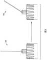
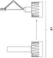
安全性在针的制造中是重要的考虑因素,特别是用于医疗用途的针。另一个考虑因素是舒适水平,或者减少与使用针相关联的疼痛。小规格针通常用于递送小剂量的药物,以便使不适最小化。然而,如果插入力与针不同轴,则较小规格的针在使用期间更容易弯曲、屈曲和扭结。例如,图1示出了用于附接到笔注射器的小规格笔针100。如图所示,在使用期间该细针可能变得弯曲或扭结。因此,需要防止小规格针在使用期间弯曲。大多数现有的用于针的安全产品要求主动安全,其中用户将必须物理地激活安全机构。如本文所述,本发明的实施例依靠被动安全机构起作用,使得优选地不由用户手动激活。Safety is an important consideration in the manufacture of needles, especially needles for medical use. Another consideration is comfort level, or reducing pain associated with needle use. Small gauge needles are often used to deliver small doses of medication in order to minimize discomfort. However, smaller gauge needles are more prone to bending, buckling and kinking during use if the insertion force is not coaxial with the needle. For example, Figure 1 shows a small
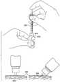
在某些情况下,如图2所示,例如从药瓶202通过针204充注注射器200或者将针206插入皮肤208中,针206的方向很重要。在这些情况下,提供增加以期望的角度插入针的可能性并且降低针弯曲的可能性的机构将是有帮助的。最后,一些患者希望不要看到针穿透他们的皮肤。In some cases, as shown in FIG. 2, such as
发明内容SUMMARY OF THE INVENTION
本发明的示例性实施例克服了上文讨论的缺陷,并且通过提供回缩机构和针围绕物提供了额外的益处,该回缩装置和针护罩在注射期间转移针上的载荷并且引导针,以帮助防止弯曲和/或屈曲。另外的实施例通过在回缩机构返回至预注射状态时锁定来防止针被多次使用。本发明的实施例还通过将针围住使得用户看不到针穿透皮肤而解决了用户不看到针进入其皮肤的偏好。Exemplary embodiments of the present invention overcome the above-discussed deficiencies and provide additional benefits by providing a retraction mechanism and needle enclosure that transfer load on the needle and guide the needle during injection , to help prevent bending and/or buckling. Additional embodiments prevent the needle from being used multiple times by locking when the retraction mechanism returns to the pre-injection state. Embodiments of the present invention also address the user's preference for not seeing the needle enter their skin by enclosing the needle so that the user cannot see the needle penetrating the skin.
附图说明Description of drawings
从下文参照相关附图对实施例示例的描述得出本发明的设计的更多细节、特征和优点。Further details, features and advantages of the design of the present invention emerge from the following description of embodiments of examples with reference to the associated drawings.
图1示出了由于插入力导致的笔针座弯曲;Figure 1 shows the bending of the pen needle holder due to insertion force;
图2示出了正在被充注的注射器和正在被插入皮肤中的笔针;Figure 2 shows the syringe being filled and the needle being inserted into the skin;
图3示出了根据本发明的第一示例性实施例的针护罩;Figure 3 shows a needle shield according to a first exemplary embodiment of the present invention;
图4示出了图3的针护罩,该针护罩是对常规针护罩的替代;Figure 4 shows the needle shield of Figure 3, which is an alternative to conventional needle shields;
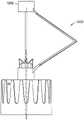
图5示出了本发明的第二示例性实施例;Figure 5 shows a second exemplary embodiment of the present invention;
图6示出了本发明的第三示例性实施例;Figure 6 shows a third exemplary embodiment of the present invention;
图7示出了本发明的第四示例性实施例;Figure 7 shows a fourth exemplary embodiment of the present invention;
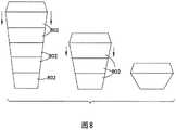
图8是示出了本发明的可伸缩示例性实施例的侧视图;Figure 8 is a side view showing a scalable exemplary embodiment of the present invention;
图9是图8的实施例的俯视图;Figure 9 is a top view of the embodiment of Figure 8;
图10是图8的实施例的横截面视图;Figure 10 is a cross-sectional view of the embodiment of Figure 8;
图11示出了用于与本发明的锁定实施例一起使用的卡扣钩;Figure 11 shows a snap hook for use with a locking embodiment of the present invention;
图12示出了在第一构造中的锁定实施例;Figure 12 shows the locking embodiment in the first configuration;
图13示出了在第二构造中的锁定实施例;和Figure 13 shows the locking embodiment in the second configuration; and
图14示出了本发明的分离臂实施例。Figure 14 shows a split arm embodiment of the present invention.
在所有附图中,类似的附图标记应当理解为代表类似的元件、特征和结构。Throughout the drawings, similar reference numbers should be understood to represent similar elements, features and structures.
具体实施方式Detailed ways
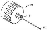
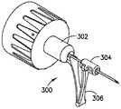
本发明的示例性实施例在图3A至图3C中示出。图3A示出了本发明的示例性实施例所适用的标准笔针。图3B至图3C示出了添加到笔针100以形成自动回缩机构的针护罩300。按照最初的构造,针护罩300在针护罩300的基部302处连接到笔针100的针柱110。针112的端部包含在围绕壳体304内。基部302和围绕壳体304通过铰接臂306连接。针护罩300优选地由预加载的塑料模制件(例如,聚丙烯或类似物)形成。如图3B所示,在初始状态,针的端部112隐藏在围绕壳体304内。当针被插入时,围绕壳体304随着针穿透皮肤而沿针滑向针柱110。铰接臂306弯曲以适应该滑动运动。然后,当患者拔出针时,铰接臂306的弹性力将围绕壳体304推回到针的端部。因此,针末端有利地保持隐藏在围绕壳体304中,以防止意外针刺,并且为不希望看到针穿透的患者提供舒适。铰接臂306和围绕壳体204组合起来,除了沿更直的线引导针穿过围绕壳体之外,还将屈曲载荷从针上转移掉,以防止针在使用期间弯曲。Exemplary embodiments of the present invention are shown in Figures 3A-3C. Figure 3A shows a standard stylus to which exemplary embodiments of the present invention are applicable. Figures 3B-3C illustrate
本发明的实施例可以有利地与任何注射产品集成,并且提供单侧患者端安全性,即贯穿整个注射程序隐藏暴露的针。Embodiments of the present invention can be advantageously integrated with any injection product and provide unilateral patient-side safety, ie concealing the exposed needle throughout the entire injection procedure.
针护罩300优选地由预加载的塑料模制件形成,该预加载的塑料模制件在穿透皮肤期间当向它施加力时将预加载的势能转化为动能。该转换后的能量允许护罩自动回缩到其初始位置,以防止一旦用户拔出针后的任何意外针刺。此外,自动锁定机构可以并入到装置中,以防止在其上安装了护罩300的针的重复使用。一旦装置在第一次插入后回缩到其初始位置,自动锁定机构便有利地激活,以防止重复使用和污染。The
图4示出了具有常规针护罩402的常规笔针400以及用本发明的实施例404替代常规针护罩402的笔针400。Figure 4 shows a conventional pen needle 400 with a conventional needle shield 402 and a pen needle 400 in which the conventional needle shield 402 is replaced with an embodiment 404 of the present invention.
本发明的其他示例性实施例在图5至图7中示出,以在不偏离本发明的范围和精神的情况下,展示对上文所述第一实施例可能作出的各种变化和修改。这些实施例中的每一个都示出为与笔针一起使用,但是本领域普通技术人员将很容易理解本发明的实施例可以与任何针一起使用。装置500包括连接构件502,该连接构件固定到针504的近侧端部。连接构件502可以通过连接到笔针座508的柱506的方式、或者通过直接附接到针504的近侧端部、或者通过任何其他合适的措施固定到针。第一臂510铰接地连接到连接构件502,并且如图所示轴向延伸远离针。第一臂510在其另一端部处铰接到第二臂512。第二臂512在其另一端部处铰接到可动构件514。可动构件514可滑动地附接到针。连接构件502、第一臂510、第二臂512和可动构件514组成保护性护罩500。该护罩被偏置在延伸的位置,使得该护罩在注射期间收缩并且当针被抽回时再次延伸。可动构件514优选地在针插入期间与皮肤接触,并为针提供引导,改善插入性能。可动构件514优选地封装针516的远侧端部,以在使用前和使用后提供保护,避免意外刺伤,并且如果需要,可以将锁定机构(未示出)并入以锁定装置并防止第二次使用。Other exemplary embodiments of the present invention are shown in FIGS. 5-7 to illustrate various changes and modifications that may be made to the first embodiment described above without departing from the scope and spirit of the present invention . Each of these embodiments is shown for use with a pen needle, but one of ordinary skill in the art will readily understand that embodiments of the present invention may be used with any needle.
针护罩600在图6中示出。针护罩600与前面描述的实施例500基本相似,但是包括在第一臂610和第二臂612之间的偏置壳体602,以在可动构件614沿着针的长度滑动时提供第二臂612在偏置壳体602内向内和向外的运动。
针护罩700在图7中示出。针护罩700提供单个曲线臂702,该曲线臂固定在针704的近侧端部处,并且可滑动地连接到针716的远侧端部。
另一个针护罩实施例800在图8至图10中示出。该实施例800有利地完全包住针。针护罩800包括一系列嵌套的部段802,这些部段被偏置或者弹簧加载在延伸的位置。当插入针时,嵌套的部分塌缩以露出针,但该嵌套的部分保持压靠皮肤,使得针对用户保持不可见。当抽回针时,嵌套的部段802再次延伸以封装针。图8示出了嵌套的部段从完全延伸到完全塌缩(针被插入)的一系列视图的侧视图。图9是针护罩800的俯视图。图9是示出在延伸的初始位置和在塌缩的位置的针护罩800的横截面侧视图。最远侧的部段802优选地连接到弹簧或其他偏置装置,以便嵌套的部段802在针被抽回时延伸到延伸的位置。Another needle shield embodiment 800 is shown in FIGS. 8-10 . This embodiment 800 advantageously completely encloses the needle. Needle shield 800 includes a series of nested
现在将结合图11至图13描述本文所述的用于与针护罩一起使用的锁定机构。图11示出了用于在锁定机构中使用的卡扣钩1100。该卡扣钩包括定向为指向内和指向下的多个倒钩1102,所留下的空间小于针的规格,锁定机构将与该规格的针一起使用。图12示出了并入锁定机构的针护罩1200。如图所示,卡扣钩1100最初位于针的近侧端部。当使用针时,围绕壳体1202沿针向下滑动,并且与卡扣钩1100接合。在卡扣钩1100上提供了突出部1104,以在针第一次完全插入时(即,在围绕壳体1202第一次一直滑到针的近侧端部时)将卡扣钩锁定在围绕壳体1202中。一旦卡扣钩1100已经锁定在围绕壳体1202中并且一旦针被抽回,围绕壳体1202便返回到针的远侧端部并拉动卡扣钩1100随之一起。当卡扣钩到达针的远侧端部时,倒钩1102自然地向内挠曲,因此如果再次尝试插入针,则该倒钩会与针相干扰。The locking mechanism described herein for use with a needle shield will now be described in conjunction with FIGS. 11-13 . Figure 11 shows a
图14示出了针护罩1400的又一个实施例。在该实施例中,第一臂1402和第二臂1404被分开以形成两对臂。Figure 14 shows yet another embodiment of a
上文所述的实施例旨在说明本发明的实施例,而不是旨在限制。本领域普通技术人员将容易地理解,在不偏离如本文所描述和示出的本发明的范围和精神的情况下,可以对本文所述的实施例进行各种变化和修改。The embodiments described above are intended to illustrate embodiments of the present invention, and are not intended to be limiting. Those of ordinary skill in the art will readily appreciate that various changes and modifications of the embodiments described herein can be made without departing from the scope and spirit of the invention as described and illustrated herein.
Claims (7)
Translated fromChineseApplications Claiming Priority (3)
| Application Number | Priority Date | Filing Date | Title |
|---|---|---|---|
| US201762488006P | 2017-04-20 | 2017-04-20 | |
| US62/488,006 | 2017-04-20 | ||
| PCT/US2018/028394WO2018195326A1 (en) | 2017-04-20 | 2018-04-19 | Passive safety needle shield |
Publications (2)
| Publication Number | Publication Date |
|---|---|
| CN110536710A CN110536710A (en) | 2019-12-03 |
| CN110536710Btrue CN110536710B (en) | 2022-07-22 |
Family
ID=63856477
Family Applications (1)
| Application Number | Title | Priority Date | Filing Date |
|---|---|---|---|
| CN201880025835.9AActiveCN110536710B (en) | 2017-04-20 | 2018-04-19 | Passive Safety Needle Guard |
Country Status (6)
| Country | Link |
|---|---|
| US (2) | US11559632B2 (en) |
| EP (1) | EP3612257A4 (en) |
| JP (2) | JP7112614B2 (en) |
| CN (1) | CN110536710B (en) |
| CA (1) | CA3055792A1 (en) |
| WO (1) | WO2018195326A1 (en) |
Citations (4)
| Publication number | Priority date | Publication date | Assignee | Title |
|---|---|---|---|---|
| US5697907A (en)* | 1993-07-20 | 1997-12-16 | Graphic Controls Corporation | Safety catheter |
| CN1449845A (en)* | 2002-03-21 | 2003-10-22 | 贝克顿迪肯森公司 | Safety device |
| CN1878584A (en)* | 2003-11-13 | 2006-12-13 | 特殊健康产品公司 | Safety shield for medical needles |
| CN103945883A (en)* | 2011-07-25 | 2014-07-23 | 安全注射器有限公司 | Folding panel needle guard |
Family Cites Families (14)
| Publication number | Priority date | Publication date | Assignee | Title |
|---|---|---|---|---|
| US4892521A (en)* | 1988-08-03 | 1990-01-09 | Lincoln Mills, Inc. | Protective cover for hypodermic needle |
| US4955866A (en)* | 1988-10-19 | 1990-09-11 | University Of Florida | Hypodermic needle recapping device |
| US5078697A (en) | 1990-11-28 | 1992-01-07 | Rammler David H | Syringe needle guard |
| US5250031A (en)* | 1992-12-14 | 1993-10-05 | The George Washington University | Locking needle cover |
| US5344408A (en)* | 1993-08-06 | 1994-09-06 | Becton, Dickinson And Company | Break-away safety shield for needle cannula |
| US6629959B2 (en)* | 1996-02-27 | 2003-10-07 | Injectimed, Inc. | Needle tip guard for percutaneous entry needles |
| AU3708902A (en) | 2001-05-04 | 2002-11-07 | Becton Dickinson & Company | Passively activated safely needle |
| US6623458B2 (en) | 2001-09-26 | 2003-09-23 | B. Braun Melsungen, Ag | Spring launched needle safety clip |
| CA2422472A1 (en)* | 2002-03-19 | 2003-09-19 | Volker Niermann | Needle assembly |
| US20030220587A1 (en)* | 2002-05-23 | 2003-11-27 | Becton Dickinson And Company | Medical device |
| CA2625030A1 (en)* | 2005-10-17 | 2007-04-26 | Becton, Dickinson And Company | Shieldable needle assembly containing reduced stress living hinge and methods of manufacture |
| GB0603926D0 (en) | 2006-02-28 | 2006-04-05 | Owen Mumford Ltd | Syringes |
| CN201519342U (en) | 2009-11-06 | 2010-07-07 | 刘桂玉 | Novel syringe needle |
| JP5601741B1 (en) | 2014-01-21 | 2014-10-08 | 応用電子工業株式会社 | Feathered needle |
- 2018
- 2018-04-19CNCN201880025835.9Apatent/CN110536710B/enactiveActive
- 2018-04-19JPJP2019555439Apatent/JP7112614B2/enactiveActive
- 2018-04-19CACA3055792Apatent/CA3055792A1/enactivePending
- 2018-04-19EPEP18786972.2Apatent/EP3612257A4/ennot_activeWithdrawn
- 2018-04-19USUS16/498,559patent/US11559632B2/enactiveActive
- 2018-04-19WOPCT/US2018/028394patent/WO2018195326A1/ennot_activeCeased
- 2022
- 2022-05-30JPJP2022087411Apatent/JP2022115107A/enactivePending
- 2022-11-10USUS18/054,343patent/US20230141155A1/enactivePending
Patent Citations (4)
| Publication number | Priority date | Publication date | Assignee | Title |
|---|---|---|---|---|
| US5697907A (en)* | 1993-07-20 | 1997-12-16 | Graphic Controls Corporation | Safety catheter |
| CN1449845A (en)* | 2002-03-21 | 2003-10-22 | 贝克顿迪肯森公司 | Safety device |
| CN1878584A (en)* | 2003-11-13 | 2006-12-13 | 特殊健康产品公司 | Safety shield for medical needles |
| CN103945883A (en)* | 2011-07-25 | 2014-07-23 | 安全注射器有限公司 | Folding panel needle guard |
Also Published As
| Publication number | Publication date |
|---|---|
| JP2020517318A (en) | 2020-06-18 |
| JP2022115107A (en) | 2022-08-08 |
| JP7112614B2 (en) | 2022-08-04 |
| US20230141155A1 (en) | 2023-05-11 |
| WO2018195326A1 (en) | 2018-10-25 |
| EP3612257A4 (en) | 2020-08-19 |
| CN110536710A (en) | 2019-12-03 |
| CA3055792A1 (en) | 2018-10-25 |
| US20200046912A1 (en) | 2020-02-13 |
| EP3612257A1 (en) | 2020-02-26 |
| US11559632B2 (en) | 2023-01-24 |
Similar Documents
| Publication | Publication Date | Title |
|---|---|---|
| US20230201483A1 (en) | Safety needle device | |
| JP5938403B2 (en) | Safety devices for drug-filled syringes and injection devices | |
| US6981965B2 (en) | Universal passive protector for an IV catheter | |
| JP4981030B2 (en) | Protection device to protect the injection needle | |
| US11564604B2 (en) | Passive double drive member activated safety blood collection device | |
| JP5952188B2 (en) | Hoover needle with safety tube | |
| JP2010501268A (en) | Lock clip with trigger bushing | |
| CN103957971A (en) | Needle safety device | |
| BR112013003683B1 (en) | SAFETY NEEDLE DEVICE, PROTECTED NEEDLE ASSEMBLY, BLOOD COLLECTION ASSEMBLY AND METHOD FOR ACTIVATING A NEEDLE ASSEMBLY | |
| CN111093749B (en) | Improved medical device with elastically retractable safety needle | |
| JP6964659B2 (en) | Needle assembly for subcutaneous injection set | |
| WO2010121289A1 (en) | Syringe with safety sheath | |
| JP2019523069A (en) | Injection ridge capture needle shield | |
| CN110536710B (en) | Passive Safety Needle Guard | |
| EP4043048B1 (en) | Safe ejection intravenous needle | |
| CN106061540A (en) | safety conduit | |
| ES2395331T3 (en) | Resettable safety sleeve for medical needles | |
| WO2023172269A1 (en) | Safety pen needle assembly | |
| HK1184732B (en) | Safety device for a pre-filled syringe and injection device |
Legal Events
| Date | Code | Title | Description |
|---|---|---|---|
| PB01 | Publication | ||
| PB01 | Publication | ||
| SE01 | Entry into force of request for substantive examination | ||
| SE01 | Entry into force of request for substantive examination | ||
| GR01 | Patent grant | ||
| GR01 | Patent grant | ||
| TA01 | Transfer of patent application right | Effective date of registration:20220712 Address after:Massachusetts Applicant after:Enbeckta Address before:new jersey Applicant before:Becton, Dickinson and Co. | |
| TA01 | Transfer of patent application right | ||
| CP03 | Change of name, title or address | Address after:Massachusetts USA Patentee after:Yingbaida Co. Country or region after:U.S.A. Address before:Massachusetts USA Patentee before:Enbeckta Country or region before:U.S.A. | |
| CP03 | Change of name, title or address |