CN110536614B - Nozzle and heater assembly for inhalation device - Google Patents
Nozzle and heater assembly for inhalation deviceDownload PDFInfo
- Publication number
- CN110536614B CN110536614BCN201880018341.8ACN201880018341ACN110536614BCN 110536614 BCN110536614 BCN 110536614BCN 201880018341 ACN201880018341 ACN 201880018341ACN 110536614 BCN110536614 BCN 110536614B
- Authority
- CN
- China
- Prior art keywords
- heater
- resistive element
- substrate
- assembly
- suction nozzle
- Prior art date
- Legal status (The legal status is an assumption and is not a legal conclusion. Google has not performed a legal analysis and makes no representation as to the accuracy of the status listed.)
- Active
Links
Images


Classifications
- A—HUMAN NECESSITIES
- A24—TOBACCO; CIGARS; CIGARETTES; SIMULATED SMOKING DEVICES; SMOKERS' REQUISITES
- A24F—SMOKERS' REQUISITES; MATCH BOXES; SIMULATED SMOKING DEVICES
- A24F40/00—Electrically operated smoking devices; Component parts thereof; Manufacture thereof; Maintenance or testing thereof; Charging means specially adapted therefor
- A24F40/10—Devices using liquid inhalable precursors
- A—HUMAN NECESSITIES
- A24—TOBACCO; CIGARS; CIGARETTES; SIMULATED SMOKING DEVICES; SMOKERS' REQUISITES
- A24F—SMOKERS' REQUISITES; MATCH BOXES; SIMULATED SMOKING DEVICES
- A24F40/00—Electrically operated smoking devices; Component parts thereof; Manufacture thereof; Maintenance or testing thereof; Charging means specially adapted therefor
- A24F40/40—Constructional details, e.g. connection of cartridges and battery parts
- A24F40/46—Shape or structure of electric heating means
- A—HUMAN NECESSITIES
- A24—TOBACCO; CIGARS; CIGARETTES; SIMULATED SMOKING DEVICES; SMOKERS' REQUISITES
- A24F—SMOKERS' REQUISITES; MATCH BOXES; SIMULATED SMOKING DEVICES
- A24F47/00—Smokers' requisites not otherwise provided for
- A—HUMAN NECESSITIES
- A61—MEDICAL OR VETERINARY SCIENCE; HYGIENE
- A61M—DEVICES FOR INTRODUCING MEDIA INTO, OR ONTO, THE BODY; DEVICES FOR TRANSDUCING BODY MEDIA OR FOR TAKING MEDIA FROM THE BODY; DEVICES FOR PRODUCING OR ENDING SLEEP OR STUPOR
- A61M15/00—Inhalators
- A61M15/0001—Details of inhalators; Constructional features thereof
- A61M15/0021—Mouthpieces therefor
- A—HUMAN NECESSITIES
- A61—MEDICAL OR VETERINARY SCIENCE; HYGIENE
- A61M—DEVICES FOR INTRODUCING MEDIA INTO, OR ONTO, THE BODY; DEVICES FOR TRANSDUCING BODY MEDIA OR FOR TAKING MEDIA FROM THE BODY; DEVICES FOR PRODUCING OR ENDING SLEEP OR STUPOR
- A61M15/00—Inhalators
- A61M15/06—Inhaling appliances shaped like cigars, cigarettes or pipes
- H—ELECTRICITY
- H05—ELECTRIC TECHNIQUES NOT OTHERWISE PROVIDED FOR
- H05B—ELECTRIC HEATING; ELECTRIC LIGHT SOURCES NOT OTHERWISE PROVIDED FOR; CIRCUIT ARRANGEMENTS FOR ELECTRIC LIGHT SOURCES, IN GENERAL
- H05B3/00—Ohmic-resistance heating
- H05B3/02—Details
- H05B3/04—Waterproof or air-tight seals for heaters
- H—ELECTRICITY
- H05—ELECTRIC TECHNIQUES NOT OTHERWISE PROVIDED FOR
- H05B—ELECTRIC HEATING; ELECTRIC LIGHT SOURCES NOT OTHERWISE PROVIDED FOR; CIRCUIT ARRANGEMENTS FOR ELECTRIC LIGHT SOURCES, IN GENERAL
- H05B3/00—Ohmic-resistance heating
- H05B3/10—Heating elements characterised by the composition or nature of the materials or by the arrangement of the conductor
- H—ELECTRICITY
- H05—ELECTRIC TECHNIQUES NOT OTHERWISE PROVIDED FOR
- H05B—ELECTRIC HEATING; ELECTRIC LIGHT SOURCES NOT OTHERWISE PROVIDED FOR; CIRCUIT ARRANGEMENTS FOR ELECTRIC LIGHT SOURCES, IN GENERAL
- H05B3/00—Ohmic-resistance heating
- H05B3/20—Heating elements having extended surface area substantially in a two-dimensional plane, e.g. plate-heater
- A—HUMAN NECESSITIES
- A61—MEDICAL OR VETERINARY SCIENCE; HYGIENE
- A61M—DEVICES FOR INTRODUCING MEDIA INTO, OR ONTO, THE BODY; DEVICES FOR TRANSDUCING BODY MEDIA OR FOR TAKING MEDIA FROM THE BODY; DEVICES FOR PRODUCING OR ENDING SLEEP OR STUPOR
- A61M2205/00—General characteristics of the apparatus
- A61M2205/82—Internal energy supply devices
- A61M2205/8206—Internal energy supply devices battery-operated
Landscapes
- Health & Medical Sciences (AREA)
- Engineering & Computer Science (AREA)
- Bioinformatics & Cheminformatics (AREA)
- Pulmonology (AREA)
- Anesthesiology (AREA)
- Biomedical Technology (AREA)
- Heart & Thoracic Surgery (AREA)
- Hematology (AREA)
- Life Sciences & Earth Sciences (AREA)
- Animal Behavior & Ethology (AREA)
- General Health & Medical Sciences (AREA)
- Public Health (AREA)
- Veterinary Medicine (AREA)
- Resistance Heating (AREA)
- Medicinal Preparation (AREA)
- Infusion, Injection, And Reservoir Apparatuses (AREA)
Abstract
Translated fromChinese
Description
Translated fromChinese技术领域technical field
本发明涉及一种用于吸入装置的吸嘴和加热器组件。加热器被配置成加热组合物以产生气溶胶来供使用者吸入。具体地,但非排他地,本发明涉及用于尼古丁替代治疗或吸烟代替装置的加热器。此外,本发明涉及包括该加热器的吸嘴、包括该加热器的吸入装置以及制造该加热器的方法。The present invention relates to a nozzle and heater assembly for an inhalation device. The heater is configured to heat the composition to generate an aerosol for inhalation by the user. Specifically, but not exclusively, the present invention relates to heaters for nicotine replacement therapy or smoking replacement devices. Furthermore, the present invention relates to a suction nozzle including the heater, an inhalation device including the heater, and a method of manufacturing the heater.
尽管本申请将集中于加热含有尼古丁的组合物以供使用者吸入,但是应当理解,该加热器可以用于加热包括其他化合物(例如药物或调味剂)的组合物。Although this application will focus on heating nicotine-containing compositions for inhalation by a user, it should be understood that the heaters may be used to heat compositions that include other compounds, such as drugs or flavors.
背景技术Background technique
尼古丁替代治疗针对希望戒烟以及克服其对尼古丁依赖的人群。一种形式的尼古丁替代治疗是吸气器或吸入器,所述吸气器或吸入器的一个示例由Johnson&JohnsonLimited以商标名
除了诸如吸入器的被动式尼古丁输送装置之外,主动式尼古丁输送装置以电子烟的形式存在,电子烟通常使用加热和/或超声搅拌来将包括尼古丁和/或其他调味剂、丙二醇和/或甘油的制剂蒸发/气雾化成气溶胶、雾或蒸汽以供吸入。吸入的气溶胶雾或蒸汽通常带有尼古丁和/或调味剂,而没有与可燃烟草产品相关联的气味和健康风险,并且在使用中,使用者体验到与从可燃烟草产品经历到的满足感和身体感觉类似的满足感和身体感觉,特别是在呼气方面,因为气溶胶雾或蒸汽与吸食传统可燃烟草产品时呼出的烟雾具有相似的外观。In addition to passive nicotine delivery devices such as inhalers, active nicotine delivery devices exist in the form of electronic cigarettes, which typically use heat and/or ultrasonic agitation to incorporate nicotine and/or other flavoring agents, propylene glycol and/or glycerin The formulation is evaporated/aerosolized into an aerosol, mist or vapor for inhalation. Inhaled aerosol mists or vapors typically carry nicotine and/or flavorings without the odor and health risks associated with combustible tobacco products, and in use, the user experiences the same satisfaction experienced from combustible tobacco products Satisfaction and bodily sensations similar to physical sensations, especially with regard to exhalation, as aerosol mist or vapor has a similar appearance to the smoke exhaled when smoking traditional combustible tobacco products.
本领域技术人员应当理解,本文所用的术语“吸烟代替装置”包括但不限于电子尼古丁输送系统(ENDS)、电子烟(electronic cigarettes)、电子烟(e-cigarettes)、电子烟(e-cigs)、蒸发香烟、烟斗、雪茄、小雪茄、蒸发器和类似性质的装置,其功能是产生供使用者吸入的气溶胶雾或蒸汽。一些代替装置是一次性的;其他的是可重复使用的,具有可更换和可再填充的部件。本发明主要涉及后者,特别是涉及需要或拥有电源以实现气雾化的“主动式”装置。It will be understood by those skilled in the art that the term "smoking replacement device" as used herein includes, but is not limited to, electronic nicotine delivery systems (ENDS), electronic cigarettes, electronic cigarettes (e-cigarettes), electronic cigarettes (e-cigs) , Vaporizing cigarettes, pipes, cigars, cigarillos, vaporizers and devices of similar nature, the function of which is to generate an aerosol mist or vapor for inhalation by the user. Some replacement devices are disposable; others are reusable, with replaceable and refillable parts. The present invention is primarily concerned with the latter, and in particular with "active" devices that require or possess a power source to effect aerosolization.
吸烟代替装置通常类似于传统的香烟且呈圆柱形,其在一端具有吸嘴,使用者可以通过该吸嘴抽吸气溶胶、雾或蒸汽以供吸入。这些装置通常共用几个通用部件;诸如电池的电源,用于保持待蒸发的液体(通常称为电子液体)的贮存器,用于雾化和/或蒸发液体从而产生气溶胶、雾或蒸汽的诸如加热器的蒸发部件,以及可操作以响应于来自由使用者操作的开关的致动信号致动蒸发部件、或者配置成检测使用者何时通过吸气从吸嘴抽吸空气的控制电路。Smoking replacement devices are generally cylindrical in shape similar to conventional cigarettes and have a mouthpiece at one end through which a user can draw aerosol, mist or vapor for inhalation. These devices often share several common components; a power source such as a battery, a reservoir for holding the liquid to be vaporized (often referred to as e-liquid), a device for atomizing and/or evaporating the liquid to produce an aerosol, mist or vapor An evaporative component, such as a heater, and a control circuit operable to actuate the evaporative component in response to an actuation signal from a switch operated by the user, or configured to detect when the user draws air from the mouthpiece by inhaling.
最常见形式的主动式吸烟代替装置被称为芯丝装置,芯丝装置的一个示例在图1中示意性地示出。蒸发部件包括芯(3),该芯可以是坚硬的或柔性的、浸润在电子液体中,其中加热丝(5)缠绕在该芯(3)上。芯丝装置通常放置在含有流体的贮存器内,以便其中的液体可以被芯吸收。完整的组件通常被称为“盒雾化器”(其是单词盒和雾化器的合成词)。在使用中,电流流过丝(5)来对其进行电阻加热,这种热量传递到芯(3)中的电子液体使其蒸发。常常被浸泡的芯(3)通常含有比单次吸入时蒸发的电子液体更多的电子液体。这增加了芯(3)的热质量,并且意味着由丝(5)产生的热量被不必要地消耗以加热所有的电子液体而不是实际需要蒸发的量。加热过剩的液体会降低装置的能量效率。此外,丝(5)与芯(3)被间隔开以防止丝(5)烧坏芯(3)。这减少了传递到芯的热量,并且意味着丝(5)必须被过度供电以补偿丝的热量的辐射耗散以及加热大的基板和大量液体的低效率。这再次降低了装置的能量效率。此外,过剩的电子液体和反复加热到较高温度会增加使用者接收到比预期剂量更大剂量的尼古丁的风险,并增加尼古丁和赋形剂降解的可能性。The most common form of active smoking replacement device is referred to as a core wire device, one example of which is shown schematically in FIG. 1 . The evaporation part comprises a wick (3), which may be rigid or flexible, immersed in the e-liquid, wherein a heating wire (5) is wound around the wick (3). The core wire device is typically placed within a fluid-containing reservoir so that the fluid therein can be absorbed by the core. The complete assembly is often referred to as a "box atomizer" (which is a compound word for the words box and atomizer). In use, electrical current flows through the wire (5) to resistively heat it, and this heat is transferred to the e-liquid in the wick (3) causing it to evaporate. Frequently soaked wicks (3) typically contain more e-liquid than evaporated during a single inhalation. This increases the thermal mass of the wick (3) and means that the heat generated by the wire (5) is unnecessarily dissipated to heat all the e-liquid rather than the amount that actually needs to be evaporated. Heating excess liquid reduces the energy efficiency of the device. In addition, the wire (5) is spaced from the core (3) to prevent the wire (5) from burning the core (3). This reduces heat transfer to the core and means that the wire (5) must be over powered to compensate for the radiative dissipation of the wire's heat and the inefficiency of heating large substrates and large volumes of liquid. This again reduces the energy efficiency of the device. Additionally, excess e-liquid and repeated heating to higher temperatures can increase the risk of users receiving larger than intended doses of nicotine and increase the likelihood of nicotine and excipient degradation.
已知的电子烟加热器的另一个问题是其设计不适合自动化。Another problem with known e-cigarette heaters is that their design is not suitable for automation.
已知的电子烟的又一个问题是使用者可以用不适用于该装置的电子液体再次填充他们的装置,因此他们可能吸食在加热时发生不良反应的较高水平的尼古丁或添加剂。结果,使用者可能暴露于过量的尼古丁或潜在的有害副产物。Yet another problem with known e-cigarettes is that users can refill their devices with e-liquids that are not suitable for the device, so they may inhale higher levels of nicotine or additives that react badly when heated. As a result, users may be exposed to excess nicotine or potentially harmful by-products.
WO2016/005533公开了一种用于电动操作的气溶胶产生系统的基本平坦的气溶胶形成盒。所述盒包括基层,所述基层包括多个空腔和多个气溶胶形成基板,所述气溶胶形成基板布置在所述基层上并且包括含有烟草的材料,所述含有烟草材料具有可从所述气溶胶形成基板释放的挥发性烟草味道化合物。所述基层和所述多个气雾形成基板在基本上平面状的接触表面处接触,并且所述盒还包括至少一个电加热元件以加热气溶胶形成基板。理想地,所述盒最初是密封的物品,并且在插入吸入装置的主体之前,密封件被破坏或移除,并且在插入之后,吸嘴部件然后也被附接到吸入装置主体。所述吸嘴和所述盒是单独的部件。WO2016/005533 discloses a substantially flat aerosol-forming cartridge for an electrically operated aerosol-generating system. The box includes a base layer including a plurality of cavities and a plurality of aerosol-forming substrates disposed on the base layer and including a tobacco-containing material having a The aerosol-forming substrates release volatile tobacco flavor compounds. The base layer and the plurality of aerosol-forming substrates are in contact at substantially planar contact surfaces, and the cartridge further includes at least one electrical heating element to heat the aerosol-forming substrates. Ideally, the case is initially a sealed item and the seal is broken or removed prior to insertion into the body of the inhalation device, and after insertion, the mouthpiece member is then also attached to the body of the inhalation device. The suction nozzle and the cartridge are separate components.
US2014/0060554描述了一种包括一个或多个微型加热器的电子吸烟器具。这提供了改进的气溶胶输送。特别地,所述微型加热器提供对气溶胶前体组合物的蒸发的改进控制,并提供实现一致的气雾化的降低的功率要求。该文件还涉及在吸烟器具中形成气溶胶的方法。所述电子吸烟器具可以包括吸嘴部件,所述微型加热器可设置和/或容纳在所述吸嘴部件中。在一些实施例中,所述微型加热器设置在基板上或基板内,并且所述基板可以包含在所述吸嘴内。在其他实施例中,所述微型加热器设置在所述吸烟器具的主体内,并且包括气溶胶前体组合物的可更换基板插设在所述电子吸烟器具中。US2014/0060554 describes an electronic smoking article comprising one or more micro heaters. This provides improved aerosol delivery. In particular, the micro-heaters provide improved control over the evaporation of the aerosol precursor composition and provide reduced power requirements for consistent aerosolization. This document also relates to a method of forming an aerosol in a smoking article. The electronic smoking article may include a mouthpiece in which the micro-heater may be provided and/or housed. In some embodiments, the micro-heaters are disposed on or within a substrate, and the substrate may be contained within the suction nozzle. In other embodiments, the micro-heater is disposed within the body of the smoking article and a replaceable substrate comprising an aerosol precursor composition is inserted into the electronic smoking article.
US2013/0255702描述了一种吸烟器具,其包括导电基板,并且具体地是用于例如在电子吸烟器具中焦耳加热的导电基板。特别地,该文件描述了由导电基板形成的电阻加热元件。所述导电基板包括导电材料和碳质添加剂(例如粘合剂材料)。所述导电基板由于经受煅烧条件而被碳化,以有效地将碳质添加剂还原成其碳骨架。已经发现,相对于未碳化的相同配方的基板,这种碳化基板具有令人惊讶的改进的耐受性。所述碳化基板可以包括气溶胶前体材料。形成的电阻加热元件可以包括在电子吸烟器具中,从而以单个整体部件同时提供电阻加热和气溶胶形成。还描述了一种吸嘴部件,该吸嘴部件包含形成其整体部分的导电基板。US2013/0255702 describes a smoking article comprising a conductive substrate, and in particular a conductive substrate for Joule heating eg in electronic smoking articles. In particular, this document describes resistive heating elements formed from conductive substrates. The conductive substrate includes a conductive material and a carbonaceous additive (eg, a binder material). The conductive substrate is carbonized as a result of being subjected to calcination conditions to effectively reduce the carbonaceous additive to its carbon skeleton. Such carbonized substrates have been found to have surprisingly improved resistance relative to uncarbonized substrates of the same formulation. The carbonized substrate may include an aerosol precursor material. The formed resistive heating element can be included in an electronic smoking article to provide both resistive heating and aerosol formation in a single integral part. A nozzle assembly is also described that includes a conductive substrate forming an integral part thereof.
其公开内容与上述WO2016/005533的公开内容非常相似的WO2016/005530还公开了一种用于电动操作的气溶胶产生系统的基本平坦的气溶胶形成盒。图3A,3B具体公开了具有上部和下部的盒,所述上部和下部一起在内部限定凹槽,并且在所述上部和所述下部之间装有在基本平面状的接触表面处接触的加热器和气溶胶形成基板。WO2016/005530, whose disclosure is very similar to that of WO2016/005533 described above, also discloses a substantially flat aerosol-forming cartridge for an electrically operated aerosol-generating system. Figures 3A, 3B specifically disclose a box having an upper and lower portion that together define a groove internally and between which is fitted with heating contacting at a substantially planar contact surface The device and the aerosol form the substrate.
在过去几年中,吸烟代替装置的普及和使用已迅速增长。虽然最初的市场定位是用作辅助器来帮助希望戒食可燃烟草的习惯性吸烟者,但消费者越来越多地将吸烟代替装置视为理想的生活配件。此外,从监管范式到减少烟草危害范式的变化进一步促进了消费者对这些产品的使用。这已经引起了人们的关注,即吸烟代替装置可能对儿童、年轻人和那些目前未参与可燃烟草产品消费的人具有吸引力。此外,关于长期使用吸烟代替装置对健康的长期影响、以及尤其是医疗保健专业人士对消费者缺乏有关使用吸烟代替装置以及相关联的液体的信息从而阻止他们就其使用做出明智决定的担忧的持续科学辩论仍在进行中。一个特别令人关注的领域是目前市场上可获得的许多电子液体的质量和来源。The popularity and use of smoking replacement devices has grown rapidly over the past few years. While initially marketed as an aid to assist habitual smokers looking to quit combustible tobacco, consumers increasingly see smoking-replacement devices as ideal lifestyle accessories. In addition, the change from a regulatory paradigm to a tobacco harm reduction paradigm has further facilitated consumer use of these products. This has raised concerns that smoking replacement devices may be attractive to children, young adults and those who are not currently involved in the consumption of combustible tobacco products. In addition, concerns about the long-term health effects of long-term use of smoking-substitute devices and, in particular, concerns by healthcare professionals about consumers' lack of information about the use of smoking-substitute devices and associated fluids prevent them from making informed decisions about their use The ongoing scientific debate is still ongoing. An area of particular concern is the quality and origin of the many e-liquids currently available on the market.
为了回应安全和质量问题,欧盟通过了修订的烟草产品指令(烟草及相关产品条例2016)。TPD引入了适用于吸烟代替装置的条例,这些条例将:In response to safety and quality concerns, the EU adopted the revised Tobacco Products Directive (Tobacco and Related Products Regulations 2016). The TPD has introduced regulations applicable to smoking substitute devices that will:
-通过设定再次填充储存器、容器、储罐及盒的最大尺寸来限制由于疏忽暴露于尼古丁的风险(第20.3(a)条)- Limit the risk of inadvertent exposure to nicotine by setting maximum dimensions for refilling reservoirs, containers, tanks and cartridges (Article 20.3(a))
-将液体中的尼古丁浓度限制到20毫克/毫升(第20.3(b)条)- limit nicotine concentration in liquids to 20 mg/ml (Article 20.3(b))
-禁止在液体中使用某些添加剂(第20.3(c)条)- Prohibition of the use of certain additives in liquids (Article 20.3(c))
-要求在液体制造中仅使用高纯度成分(第20.3(d)条)- Require only high-purity ingredients to be used in liquid manufacturing (Article 20.3(d))
-要求所有成分(尼古丁除外)在加热或未加热形式下不会对的人类健康构成风险(第20.3(e)条)- Require that all ingredients (except nicotine) in heated or unheated form pose no risk to human health (Article 20.3(e))
-要求所有吸烟代替装置在正常使用条件下以一致的水平输送尼古丁剂量(第20.3(f)条)- Require all smoking replacement devices to deliver nicotine doses at consistent levels under normal conditions of use (Article 20.3(f))
-要求所有产品包括儿童和防擅动标签、紧固件以及开启机构(第20.3(g)条)。- Require all products to include child and tamper-resistant labels, fasteners, and opening mechanisms (section 20.3(g)).
-要求所有产品符合某些安全和质量标准,并确保产品在使用或再次填充过程中不会破裂或泄漏(说明的第41段,倒数第二句和最后一句)。- Require all products to meet certain safety and quality standards and ensure that products do not break or leak during use or refilling (paragraph 41 of the instructions, penultimate and last sentence).
然而,即使对用于电子烟的含有尼古丁制剂的制造商和供应商引入了这种尼古丁剂量控制措施,但是芯丝装置本质上是不成熟的,并且因此多次吸入之间的剂量总是会有显著的变化。此外,由于此类设备需要最终使用者再次填充,而上述TPD等法律框架不可避免地对此几乎或根本没有控制权,因此这些最终使用者将始终能够使用他们自己的可能掺杂的液体制剂,可能会损害他们自己的健康和他人的健康。However, even with the introduction of such nicotine dose control measures to manufacturers and suppliers of nicotine-containing formulations for e-cigarettes, the core wire device is inherently immature and therefore the dose between inhalations will always be There are significant changes. Furthermore, since such devices require refilling by end users over which legal frameworks such as the aforementioned TPD inevitably have little or no control, these end users will always be able to use their own potentially adulterated liquid formulations, May harm their own health and the health of others.
考虑到前述内容设计了本发明的各种方面和实施例。Various aspects and embodiments of the present invention have been devised with the foregoing in mind.
发明内容SUMMARY OF THE INVENTION
在第一方面,提供了一种如本文中权利要求1所述的用于吸入装置的组件。In a first aspect there is provided an assembly for an inhalation device as claimed in claim 1 herein.
与上述现有技术的药物吸气器或吸入器装置相比,使用加热器加热组合物的优点在于可以特别设计制剂以将感兴趣的化合物输送至肺部或口腔。对于含有尼古丁的组合物,这意味着使用者经历增强的“冲击”,即对尼古丁的吸收速率增加。因此,这可以以更少的吸入帮助更快地减少对尼古丁的渴望,从而帮助使用者逐渐减少他们的尼古丁摄入量。The advantage of using a heater to heat the composition over the prior art pharmaceutical inhalers or inhaler devices described above is that the formulation can be specifically designed to deliver the compound of interest to the lungs or oral cavity. For compositions containing nicotine, this means that the user experiences an enhanced "shock", ie an increased rate of absorption of nicotine. Therefore, this can help reduce nicotine cravings faster with less inhalation, thereby helping users gradually reduce their nicotine intake.
与例如传统电子烟的加热器相比,本发明的加热器的另一个优点是组合物可以放置成与基板直接接触并因此被传导性地加热。热量从电阻元件部分直接传导到组合物中。在一个特定实施例中,其中加热器被施加到基板的一个表面上,并且组合物被施加到基板的另一个相对表面上,但是在与其上施加加热器的另一个表面的区域大致相同的区域中,来自加热器的热量在直接传导到组合物中之前首先通过基板的材料进行传导。在这两种情况下,组合物和加热器之间没有空隙。Another advantage of the heater of the present invention, compared to heaters such as conventional electronic cigarettes, is that the composition can be placed in direct contact with the substrate and thus heated conductively. Heat is conducted from the resistive element portion directly into the composition. In a particular embodiment, wherein the heater is applied to one surface of the substrate and the composition is applied to the other opposing surface of the substrate, but in substantially the same area as the other surface on which the heater is applied In , the heat from the heater is first conducted through the material of the substrate before being conducted directly into the composition. In both cases, there was no void between the composition and the heater.
这意味着与现有技术的芯丝加热器相比,该加热器可以在更低的温度下蒸发所需量的液体。这提高了加热器的能量效率并减少了加热器的劣化。This means that the heater can evaporate the required amount of liquid at a lower temperature than prior art core wire heaters. This improves the energy efficiency of the heater and reduces heater degradation.
当组合物设置在加热器上时,加热器被配置为加热该组合物,使得组合物的至少一部分蒸发或气雾化。技术人员应该理解,本文出现的“气雾化组合物”及其同源表达不限于气溶胶本身,而是还可以包括汽相的组合物部分。When the composition is disposed on the heater, the heater is configured to heat the composition such that at least a portion of the composition evaporates or aerosolizes. The skilled artisan will appreciate that the "aerosolized composition" and its homologous expressions appearing herein are not limited to the aerosol itself, but may also include parts of the composition in the vapor phase.
此外,可以仔细地控制沉积在加热器上的组合物的量,使得加热器仅加热必要量的组合物。因此,消除了例如由加热电子烟中的过量电子液体而导致的能量损失。结果,与现有技术的加热器相比,本发明的加热器具有低得多的热质量并且需要更少的能量以供加热。该益处与较低的加热温度相结合有助于提高装置的效率。此外,这避免了在电子烟中观察到的、可能导致制剂的使用不稳定性和毒物的形成的反复热-冷循环。Furthermore, the amount of composition deposited on the heater can be carefully controlled so that the heater only heats the necessary amount of the composition. Thus, energy losses, eg caused by heating excess e-liquid in the electronic cigarette, are eliminated. As a result, the heater of the present invention has a much lower thermal mass and requires less energy for heating than prior art heaters. This benefit, combined with the lower heating temperature, helps increase the efficiency of the device. Furthermore, this avoids the repeated heat-cool cycles observed in electronic cigarettes that can lead to instabilities in use of the formulation and the formation of toxicants.
在所述组合物沉积在所述基板的与已施加有所述加热器的表面相同的表面上的实施例中,所述加热器或其所述至少一个电阻元件部分还可以包括阻挡层,所述阻挡层用于阻止在所述电阻元件部分的加热期间产生的不希望的副产物与所述组合物混合。In embodiments in which the composition is deposited on the same surface of the substrate as the surface to which the heater has been applied, the heater or the at least one resistive element portion thereof may further comprise a barrier layer, so The barrier layer serves to prevent undesired by-products generated during heating of the resistive element portion from mixing with the composition.
取决于它们形成的方式,一些电阻加热器在通过施加电流而加热时会释放不希望的副产物。例如,在制造期间添加到电阻加热器的材料或化学品有时以挥发物形式释放,其可能在加热期间与其他化学品反应以形成潜在有害的副产物。优选的是使用者不会吸入这些副产物。所述阻挡层通过在电阻加热器和组合物之间提供物理阻挡或障碍来帮助阻止在所述至少一个电阻加热器的加热期间产生的不希望的副产物与组合物或气雾化组合物混合。Depending on how they are formed, some resistive heaters release unwanted by-products when heated by the application of an electric current. For example, materials or chemicals added to resistive heaters during manufacture are sometimes released as volatiles that may react with other chemicals during heating to form potentially harmful by-products. It is preferred that the user does not inhale these by-products. The barrier layer helps prevent undesired by-products generated during heating of the at least one resistive heater from mixing with the composition or aerosolized composition by providing a physical barrier or barrier between the resistive heater and the composition .
可选地,所述阻挡层可以由选自陶瓷、塑料和玻璃中的一种或多种的材料形成。已发现这些材料适合于提供有效的阻挡层。Alternatively, the barrier layer may be formed of a material selected from one or more of ceramics, plastics and glass. These materials have been found to be suitable for providing effective barriers.
在所述组合物沉积在所述基板的与已施加有所述加热器的表面相对的表面上的替代实施例中,所述基板本身提供阻挡以防止由于加热形成的不希望的副产物与所述组合物混合。In an alternative embodiment where the composition is deposited on the surface of the substrate opposite the surface to which the heater has been applied, the substrate itself provides a barrier to prevent unwanted by-products formed by heating from interacting with all The above composition is mixed.
所述加热器可以包括由所述基板支撑的至少两个触点,其中所述至少两个触点中的每一个的第一端连接到所述电阻元件部分,并且所述至少两个触点中的每一个的第二端布置成可连接到电源。这允许所述两个触点中的每一个的第二端连接到与所述基板分开或远离所述基板的电源。例如,所述第二端可以形成连接器的一部分,该连接器被配置为连接到互补连接器,该互补连接器又连接到电源。The heater may include at least two contacts supported by the substrate, wherein a first end of each of the at least two contacts is connected to the resistive element portion, and the at least two contacts The second end of each is arranged to be connectable to a power source. This allows the second end of each of the two contacts to be connected to a power source that is separate or remote from the substrate. For example, the second end may form part of a connector configured to connect to a complementary connector, which in turn connects to a power source.
可以通过各种不同的技术(例如丝网印刷、薄和/或厚膜印刷、激光烧蚀或这些技术的某种组合)实现电阻元件部分和触点到基板的一个或另一个表面的施加。印刷电阻元件部分和/或触点的优点在于它是成本效益的且可自动化,这与将丝缠绕在芯上的缓慢手动过程形成对比。Application of resistive element portions and contacts to one or the other surface of the substrate can be accomplished by a variety of different techniques, such as screen printing, thin and/or thick film printing, laser ablation, or some combination of these techniques. The advantage of printing resistive element sections and/or contacts is that it is cost-effective and automatable, in contrast to the slow manual process of wrapping the wire around the core.
可选地,所述至少一个电阻元件部分和触点可以由相同的材料形成,但是所述至少一个电阻元件部分比所述触点具有更小的横截面积,使得所述至少一个电阻元件部分具有更高的电阻。这允许所述电阻元件部分和触点在单个印刷行程中沉积。Alternatively, the at least one resistive element portion and the contact may be formed of the same material, but the at least one resistive element portion has a smaller cross-sectional area than the contact, such that the at least one resistive element portion have higher resistance. This allows the resistive element portion and contacts to be deposited in a single printing pass.
可选地,可以例如通过激光蚀刻来烧蚀在单次印刷行程期间沉积的材料的一部分,以形成具有横截面积减小的区域的至少一个电阻元件部分,使得所述横截面积减小的区域比所述材料的其余部分具有相对较高的电阻。该步骤将印刷步骤减少到要由电阻元件部分占据的整个面积上的单个印刷行程,使得可以稍后通过烧蚀步骤提供所需的任何细节或精加工。Alternatively, a portion of the material deposited during a single printing pass may be ablated, for example by laser etching, to form at least one resistive element portion having a region of reduced cross-sectional area such that the reduced cross-sectional area Regions have a relatively higher resistance than the rest of the material. This step reduces the printing step to a single printing pass over the entire area to be occupied by the resistive element portion, so that any detailing or finishing required can be provided later by the ablation step.
或者,所述至少一个电阻元件部分和触点可以包括不同的材料并使用单独的印刷行程沉积在所述基板上。这提供了工艺的灵活性,并且允许通过改变其中包含的各种材料成分的比例来改变所述电阻元件部分和导体的性质。Alternatively, the at least one resistive element portion and the contacts may comprise different materials and be deposited on the substrate using separate printing passes. This provides process flexibility and allows the properties of the resistive element portion and conductor to be varied by varying the proportions of the various material components contained therein.
所述至少一个电阻元件部分的长度可以长于所述至少一个电阻元件部分连接到所述触点的点之间的直线距离。这增加了所述电阻元件部分的电阻。可以通过改变所述电阻元件部分的长度来控制电阻加热器的电阻。The length of the at least one resistive element portion may be longer than the linear distance between the points at which the at least one resistive element portion is connected to the contact. This increases the resistance of the resistive element portion. The resistance of the resistive heater can be controlled by varying the length of the resistive element portion.
可选地,所述至少一个电阻元件部分可以在导体之间遵循曲折路径。已经发现这提供了所述至少一个电阻元件部分的空间有效的配置。Optionally, the at least one resistive element portion may follow a tortuous path between the conductors. This has been found to provide a space efficient configuration of the at least one resistive element portion.
可选地,所述至少一个电阻元件部分包括碳或其他元素(例如银、钌、钯)中的一种。已经发现碳具有适合于本发明的加热器的电阻特性。另一方面,与碳相比,银具有相对高的电阻温度系数,并且与单独使用碳相比,使用包括银的电阻元件部分导致电阻的更大增加。这使得更容易监测电阻的变化从而监测电阻元件部分的温度。Optionally, the at least one resistive element portion includes one of carbon or other elements (eg, silver, ruthenium, palladium). Carbon has been found to have electrical resistance properties suitable for the heater of the present invention. On the other hand, silver has a relatively high temperature coefficient of resistance compared to carbon, and the use of a resistive element portion including silver results in a greater increase in resistance than the use of carbon alone. This makes it easier to monitor changes in resistance and thus monitor the temperature of the resistive element portion.
可选地,加热器电阻元件部分可以在130℃的温度下具有5欧姆至15欧姆之间的电阻。已经发现,这是特别合适于电阻元件部分的电阻,并且与例如传统的电子烟相比,该温度表示相对低的工作温度。该电阻范围还使得能够使用标准锂聚合物电池将能量输入到加热器,同时使得能够区分温度之间的电阻。Optionally, the heater resistive element portion may have a resistance between 5 ohms and 15 ohms at a temperature of 130°C. It has been found that this is particularly suitable for the resistance of the resistive element portion, and this temperature represents a relatively low operating temperature compared to eg conventional electronic cigarettes. This resistance range also enables the use of standard lithium polymer batteries to input energy to the heater while enabling differentiation of resistance between temperatures.
所述加热器可以包括多个电阻元件部分和对应数量的触点。这为在任何一个时间启动哪些加热器提供了灵活性。The heater may include a plurality of resistive element portions and a corresponding number of contacts. This provides flexibility as to which heaters are activated at any one time.
可选地,该导体可以包括所述多个电阻元件部分中的每一个各一个的触点和为所述多个电阻元件部分中的每一个形成公共接地的另一个触点。这在基板上提供了空间有效的布置。Optionally, the conductor may comprise a contact for each of the plurality of resistive element portions and another contact forming a common ground for each of the plurality of resistive element portions. This provides a space efficient arrangement on the substrate.
所述基板可以基本上是刚性的,并且基本上是平面状的。这有助于减少基板在电阻元件部分的加热期间的变形,并且允许向基板施加力以帮助将基板插入吸入装置中。The substrate may be substantially rigid and substantially planar. This helps reduce deformation of the substrate during heating of the resistive element portion, and allows force to be applied to the substrate to assist insertion of the substrate into the suction device.
可选地,所述基板可以包括选自陶瓷、塑料或玻璃中的一种或多种的材料。已经发现这些材料至少在其热性能和机械性能方面特别适合于本发明的基板。Optionally, the substrate may comprise one or more materials selected from ceramic, plastic or glass. These materials have been found to be particularly suitable for the substrates of the present invention, at least with regard to their thermal and mechanical properties.
所述基板可以包括在围绕所述至少一个电阻元件部分或多个电阻元件部分的区域中的、例如通过激光切割形成的凹口。所述凹口减小了所述基板在围绕所述电阻元件部分的区域中的横截面积,从而减少了通过所述基板从所述电阻元件部分传递走的热量。这降低了所述基板位于所述电阻加热器下面的部分的热质量(即,在加热循环期间需要被加热的基板的量),这意味着加热基板的该部分所需的能量减少。因此,加热器的能量效率增加。所述凹口还可以用于防止制剂从电阻加热器区域迁移。The substrate may comprise a recess, eg formed by laser cutting, in a region surrounding the at least one resistive element portion or portions of the resistive element. The notch reduces the cross-sectional area of the substrate in the region surrounding the resistive element portion, thereby reducing heat transfer away from the resistive element portion through the substrate. This reduces the thermal mass of the portion of the substrate below the resistive heater (ie, the amount of substrate that needs to be heated during a heating cycle), which means that less energy is required to heat that portion of the substrate. Therefore, the energy efficiency of the heater is increased. The notches can also be used to prevent migration of formulations from the resistive heater area.
所述至少一个电阻元件部分或所述触点中的至少一个可以具有横截面积减小的区域,使得所述横截面积减小的区域用作熔断器,如果流过所述横截面积减小的区域的电流超过某个阈值,则该熔断器失效(熔断)。所述熔断器用作防止加热器过热的安全装置。所述熔断器还在其他安全预防措施失效的情况下(例如在气溶胶产生装置的电子或软件控制器失效的情况下)用作故障保护装置。这有助于使加热器符合医疗装置的严格安全规定。At least one of the at least one resistive element portion or the contact may have a region of reduced cross-sectional area, such that the region of reduced cross-sectional area acts as a fuse if flow through the reduced cross-sectional area is reduced. If the current in a small area exceeds a certain threshold, the fuse fails (blows). The fuse acts as a safety device to prevent the heater from overheating. The fuses also serve as fail-safe devices in the event of failure of other safety precautions, such as failure of an electronic or software controller of the aerosol-generating device. This helps make the heater comply with the strict safety regulations for medical devices.
可气雾化组合物在基板上的沉积可以在制造时使用例如丝网印刷技术进行,使得基板既设有加热器,又已经装有待气雾化的组合物。该组合物可以包括预定数量的剂量。可选地,该组合物可以包括有尼古丁。The deposition of the aerosolizable composition on the substrate can be carried out at the time of manufacture using, for example, screen printing techniques, so that the substrate is both provided with the heater and already loaded with the composition to be aerosolized. The composition may include a predetermined number of doses. Optionally, the composition may include nicotine.
第一吸嘴部分和第二吸嘴部分的附接可以通过设置在第一吸嘴部分和第二吸嘴部分中的一个或两个上的卡扣配合连接器来实现。The attachment of the first suction nozzle part and the second suction nozzle part may be achieved by a snap fit connector provided on one or both of the first suction nozzle part and the second suction nozzle part.
在最优选的实施例中,所述加热器的所述至少一个电阻元件部分布置在设置于所述吸嘴的内部的流体连通装置(例如气流通道)的出口附近。如果确实气雾化组合物在通过吸嘴出口离开之前有时间到达气流通道的内表面的话,这减小了所述气流通道的、所述气雾化组合物可以在其上冷凝的长度和/或表面积。In a most preferred embodiment, the at least one resistive element portion of the heater is arranged near the outlet of a fluid communication means (eg an air flow channel) provided inside the suction nozzle. If indeed the aerosolized composition has time to reach the inner surface of the airflow channel before exiting through the nozzle outlet, this reduces the length of the airflow channel on which the aerosolized composition can condense and/or or surface area.
所述气流通道可以包括用于将所述加热器保持在所述气流通道的内部的导轨。所述气流通道可以包括第一部分和第二部分,所述加热器可以放置在所述第一部分和所述第二部分之间,使得在所述第一部分内流动的空气在所述加热器的其上已沉积有组合物的表面上方和上面流动,并且在所述第二部分内流动的空气在所述加热器的下面、在所述基板的与其上已沉积有组合物的表面相对的表面下方和上方流动。The airflow channel may include rails for retaining the heater inside the airflow channel. The airflow channel may include a first portion and a second portion, and the heater may be positioned between the first portion and the second portion such that air flowing in the first portion is at the other side of the heater. flowing over and above the surface on which the composition has been deposited, and air flowing in the second portion is below the heater, below the surface of the substrate opposite the surface on which the composition has been deposited and flow above.
所述第一和/或第二气流通道部分可以由至少一个平坦表面限定,所述至少一个平坦表面有助于形成经过加热器的层流气流,从而阻止气雾化组合物接触气流通道的内表面。The first and/or second airflow channel portions may be defined by at least one flat surface that facilitates laminar airflow across the heater to prevent the aerosolized composition from contacting the interior of the airflow channel. surface.
所述气流通道可以包括用于限制其中的空气的流动的收缩孔。在气流通道内采用收缩孔导致气流通道内的压力下降,并且可以允许在收缩孔的区域中更精确地控制(例如通过文丘里效应)气流的速度,从而允许加热器上方的气流与进入吸嘴的气流相比行进得更快。所述收缩孔还限制空气通过气流通道的流动,这提供了与通过传统香烟吸气类似的用户体验。The airflow channel may include constriction holes for restricting the flow of air therein. The use of a constriction hole in the airflow channel results in a drop in pressure within the air flow channel and may allow for more precise control (eg by the Venturi effect) of the speed of the air flow in the area of the constriction hole, allowing the airflow over the heater to be closely related to the entry nozzle The airflow travels faster than the . The constriction holes also restrict the flow of air through the airflow channel, which provides a similar user experience to inhaling through a conventional cigarette.
可选地,所述收缩孔可以位于所述加热器的上游。这提供了时间和空间以帮助离开所述收缩孔的湍流空气在其通过加热器上方的时间内返回到层流流动。Optionally, the shrink hole may be located upstream of the heater. This provides time and space to help turbulent air exiting the constriction holes to return to laminar flow during the time it passes over the heater.
可选地,第一气流通道部分和第二气流通道部分可以都包括收缩孔,并且理想地,选择尺寸和流体流动特性,使得第一气流通道部分和第二气流通道部分中的气流类似,即,在通道部分中流动的空气以大致相同的速度和质量流速行进。Optionally, both the first airflow channel portion and the second airflow channel portion may include constricted apertures, and ideally, the dimensions and fluid flow characteristics are selected such that the airflow in the first airflow channel portion and the second airflow channel portion are similar, i.e. , the air flowing in the channel section travels at approximately the same speed and mass flow rate.
所述吸嘴和加热器组件可以一起形成可更换的消耗品,当所述消耗品是新的时则已经装有组合物,并且当最初存在的所有组合物都已经气雾化并且因此所述消耗品已被消耗时,可以简单地处理该消耗品。The nozzle and heater assembly may together form a replaceable consumable that, when new, is already filled with the composition, and when all of the composition originally present has been aerosolized and thus the When a consumable has been consumed, the consumable can simply be disposed of.
在本发明的另一方面,提供了一种吸入装置,该吸入装置包括上述吸嘴和加热器组件、主体部分,所述主体部分包括:用于该装置的电源;以及控制单元。In another aspect of the present invention, there is provided an inhalation device comprising the nozzle and heater assembly described above, a main body portion including: a power source for the device; and a control unit.
这种吸入装置可以提供受控和精确的剂量、需要最少的维护(例如,不需要清洁吸嘴)并且将更卫生(例如减少由前次使用产生的残留物在吸入装置内的堆积)。由于可以更换吸嘴,因此这种吸入装置还可以保持更一致的性能水平(例如,避免吸嘴内的堵塞)。Such an inhalation device may provide a controlled and precise dose, require minimal maintenance (eg, no need to clean the mouthpiece), and will be more hygienic (eg, reduce the build-up of residues from previous use within the inhalation device). This inhalation device also maintains a more consistent level of performance (eg, avoids clogging in the nozzle) since the nozzle can be replaced.
这种吸入装置的主体部分可以另外包括可以包括彼此连通的流体入口和流体出口,当所述吸嘴连接到所述主体部分时,所述流体入口和所述流体出口中的后者与吸嘴的流体入口配合,从而完成气流通道。The body part of such an inhalation device may additionally comprise a fluid inlet and a fluid outlet which may be in communication with each other, the latter of the fluid inlet and the fluid outlet being connected to the suction nozzle when the suction nozzle is connected to the body part The fluid inlets are matched to complete the airflow channel.
可选地,所述主体部分流体入口可以位于所述主体部分的、所述吸嘴自由地附接到其上的端部附近。Alternatively, the body portion fluid inlet may be located near the end of the body portion to which the suction nozzle is freely attached.
附图说明Description of drawings
将仅通过示例并参考以下附图来描述根据本发明的各方面的一个或多个具体实施例,其中:One or more specific embodiments in accordance with aspects of the invention will be described, by way of example only, with reference to the following drawings, wherein:
图1是现有技术的电子烟的芯丝加热器的示意图。FIG. 1 is a schematic diagram of a core wire heater of an electronic cigarette in the prior art.
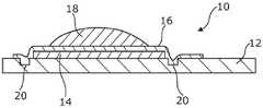
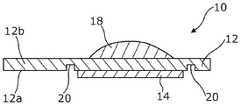
图2,2A提供了根据本发明的不同实施例的加热器的横截面图,其中一定量的组合物在第一幅图中沉积在所述基板的与其上施加有加热器的表面相同的表面上,在第二幅图中沉积在与其上施加有加热器的表面相对的表面上。Figures 2, 2A provide cross-sectional views of heaters according to various embodiments of the present invention, wherein an amount of the composition is deposited on the same surface of the substrate as the surface on which the heater is applied in the first view , deposited on the surface opposite the surface on which the heater is applied in the second image.
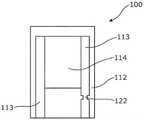
图3是根据本发明的实施例的加热器的示意性平面图。3 is a schematic plan view of a heater according to an embodiment of the present invention.
图4是根据本发明的实施例的加热器的示意性平面图。4 is a schematic plan view of a heater according to an embodiment of the present invention.
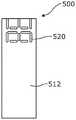
图5a-5d是根据本发明的实施例的加热器在制造的各个阶段期间的平面图。5a-5d are plan views of a heater during various stages of manufacture according to embodiments of the present invention.
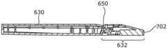
图6是根据本发明的实施例的吸入装置的侧视图。Figure 6 is a side view of an inhalation device according to an embodiment of the present invention.
图7a和图7b是分别以分解和组装形式示出的用于图6的装置的吸嘴的侧视图。Figures 7a and 7b are side views of a suction nozzle for the device of Figure 6 shown in exploded and assembled form, respectively.
图8是图6的装置沿图6中的线A-A截取的横截面图。FIG. 8 is a cross-sectional view of the device of FIG. 6 taken along line A-A in FIG. 6 .
图9a是图6的吸入装置的平面图。Figure 9a is a plan view of the inhalation device of Figure 6 .
图9b是吸入装置沿图9a中的线B-B的横截面侧视图。Figure 9b is a cross-sectional side view of the inhalation device along line B-B in Figure 9a.
图10a是根据本发明的一个或多个实施例的吸嘴的平面图。Figure 10a is a plan view of a suction nozzle according to one or more embodiments of the present invention.
图10b是吸嘴沿图10a中的线G-G的横截面侧视图。Figure 10b is a cross-sectional side view of the suction nozzle along line G-G in Figure 10a.
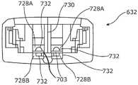
图10c是从图10a中的箭头H的方向观察到的吸嘴的后视图。Fig. 10c is a rear view of the suction nozzle viewed from the direction of arrow H in Fig. 10a.
具体实施方式Detailed ways
图2示出了根据本发明的用于吸入装置的加热器10,该加热器10包括基板12和由基板12的一部分支撑的电阻加热元件14。电阻元件部分可借助于触点(未示出)连接到电源。阻挡层16覆盖电阻元件部分14和基板12的一部分。加热器10被示出为具有已沉积在阻挡层16上的一定量的组合物18。FIG. 2 shows a
当电流流过电阻元件部分14时,电阻元件部分14的温度升高并且热量通过阻挡层16传递到组合物18。组合物18的至少一部分蒸发并分散到加热器10上方的空气中。当组合物18从加热器蒸发掉时,其会冷却,并且蒸发的组合物中的一些将冷凝以形成悬浮在空气中的组合物液滴、即气雾化组合物。该气雾化组合物可以供使用者吸入。When current flows through
阻挡层16在电阻元件部分和基板的一部分上提供密封,这阻止了在电阻加热器元件被加热时可能产生的不希望的副产物与组合物18混合、或蒸发并与供使用者吸入的气雾化组合物混合。The
凹口20靠近电阻加热器元件14的任一侧形成在基板12中。虽然未在图2的横截面中示出,但是应当理解,凹口20在进出该横截面平面的方向上延伸,以在电阻元件部分14的任一侧形成沟槽。另外的凹口(未示出)也可以靠近电阻元件部分14的另外两侧平行于该横截面平面形成。因此,凹口或沟槽形成在围绕所述至少一个电阻元件部分14的区域中。凹口20减小了基板12的横截面积,并因此减少了在凹口20的区域中通过基板的热传递。这为基板12的位于电阻元件部分14下面的区域提供一定程度的热隔离,并阻止热量在整个基板中消散。这减小了在任何特定加热循环期间由电阻元件部分14加热的基板12的体积、即加热器10的热质量。由于在基板12中消散的热量减少,因此更多的热量传递到组合物18,从而提高了加热器10的热效率。
可以通过提供基板12以及例如通过使用激光切割工艺在将要支撑电阻元件部分14的区域中形成凹口20来制造加热器10。然后可以使用丝网印刷工艺将电阻元件部分14沉积在由凹口20围绕的区域中。这将具有合适电阻的厚导电油墨膜沉积在基板上。如果要在基板上设置触点(未示出),则这些触电也可以使用丝网印刷工艺沉积在基板12上。丝网印刷提供了一种成本有效且可自动化的沉积电阻元件部分和触点的方法。触点将比电阻元件部分14具有更高的导电率。可以使用蚀刻工艺来完成丝网印刷特征的轮廓。The
基板12由陶瓷制成。然而,技术人员将理解,可以使用诸如塑料或玻璃或上述材料的组合的材料。基板的尺寸为15mm长×10mm宽×0.5mm厚,其与传统的电子烟的芯丝加热器相比相对较小。这减小了加热器10的热质量并有助于提高热效率。技术人员将理解,基板可以具有其他合适的尺寸。The
用于形成电阻元件部分14的导电油墨包括碳颗粒和银颗粒。其他成分可以包括树脂或粘合剂以及溶剂。然而,技术人员将理解,可以使用其他混合物。The conductive ink used to form the
用于形成触点的导电油墨包括导电颗粒(例金属颗粒)。然而,技术人员将理解,可以使用其他类型的颗粒(例如石墨颗粒)。The conductive ink used to form the contacts includes conductive particles (eg, metal particles). However, the skilled person will understand that other types of particles (eg graphite particles) may be used.
上述导电油墨的组合物可以适用于特定的丝网印刷工艺或针对电阻器形状或尺寸的特定取向/布局实现期望的电阻。The compositions of the conductive inks described above can be adapted for a particular screen printing process or for a particular orientation/layout of resistor shape or size to achieve the desired resistance.
在电阻加热器元件14和触点已经被丝网印刷在基板12上后,加热器通常将进行加热过程,在该加热过程中挥发性溶剂被驱除。然后,加热器可以在较高温度下进行烧结过程,以烧结导电油墨的导电或电阻成分。After the
阻挡层16由热焊接到基板12和电阻元件部分14的玻璃层制成。然而,技术人员将理解,阻挡层16可以由形成有效密封、防止不希望的挥发性副产物逸出的任何合适的材料(例如陶瓷或塑料或任何上述材料的组合)制成。The
另外,待气雾化的组合物也可以在制造期间沉积在加热器10上,使得加热器被提供为已经预先装有组合物。这种组合物也可以被丝网印刷到加热器10上。Alternatively, the composition to be aerosolized may also be deposited on the
相反,在图2A中(其中与图2的附图标记相似的附图标记用于表示相似部件),加热器10以倒置取向示出,其中加热器的电阻元件部分现在设置在基板12的底部、面向下的表面12a(即基板的第一表面)上,并且一定量的组合物18已经沉积在基板12的顶部或面向上的表面12b(即相对的第二表面)上。在这种布置中,基板本身在组合物18和加热器的电阻元件部分14之间提供阻挡,但是从加热器产生的热量仍然直接通过基板12传导到组合物中以使其气雾化并使得由此产生的气溶胶分散到上方空气中。同样,凹口20可以靠近电阻元件14的任一侧形成在基板12中。In contrast, in FIG. 2A (wherein like reference numerals as in FIG. 2 are used to denote like parts), the
如前所述,可以使用各种类型的导电油墨来形成电阻元件部分和触点。例如,碳基油墨可以用于形成电阻元件部分,而包括诸如金属或石墨的导电元素的油墨可以用于形成触点。其他成分可以包括溶剂以使这种油墨能够被印刷。另外,可以使用一种油墨来印刷电阻元件部分和触点两者。陶瓷和玻璃油墨含有提供电阻率的玻璃相、提供导电性和高的电阻温度系数的金属相两者。金属相可以包括例如银、钌、钯或其他合适金属的元素。上述的导电油墨的组合物可以适用于特定的丝网印刷工艺或针对电阻器形状或尺寸的特定取向/布局实现期望的电阻。一旦电阻加热器元件部分14和触点已经印刷在基板12上,然后,基板和印刷的加热器通常将进行加热过程以使溶剂蒸发,之后可以使用进一步的加热过程来烧结金属并熔化玻璃。As previously mentioned, various types of conductive inks can be used to form the resistive element portions and contacts. For example, carbon-based inks can be used to form resistive element portions, while inks comprising conductive elements such as metals or graphite can be used to form contacts. Other ingredients may include solvents to enable such inks to be printed. Additionally, one ink can be used to print both the resistive element portion and the contacts. Ceramic and glass inks contain both a glass phase that provides electrical resistivity, and a metallic phase that provides electrical conductivity and a high temperature coefficient of resistance. The metallic phase may include elements such as silver, ruthenium, palladium, or other suitable metals. The compositions of the conductive inks described above can be adapted for a particular screen printing process or for a particular orientation/layout of resistor shape or size to achieve the desired resistance. Once the resistive
图3和图4示出了根据本发明的可以使用不同的制造工艺制造的加热器的进一步实施例。应注意,这些图示出的是简化的示意图。为清楚起见,省略了例如凹口和阻挡层的某些特征。然而,技术人员将理解,这些省略的特征和其他特征也可以与这些描述的实施例一起使用。Figures 3 and 4 show further embodiments of heaters according to the present invention that can be manufactured using different manufacturing processes. It should be noted that these figures show simplified schematic diagrams. Certain features such as notches and barriers have been omitted for clarity. However, the skilled person will understand that these omitted features and other features may also be used with the described embodiments.
首先参考图3,加热器100包括基板112、电阻元件部分114和两个触点113。电阻元件部分114和触点113由不同的材料形成,即它们具有不同的组合物(例如上述组合物),使得触点113比电阻元件部分114更具导电性。因此,电阻元件部分114和触点在单独的印刷行程中沉积。一次印刷行程将沉积更具电阻性的导电油墨以形成电阻元件部分114,另一次印刷行程将沉积更具导电性的油墨以形成触点113。可以首先沉积电阻元件部分114然后沉积触点113,反之亦然。Referring first to FIG. 3 ,
加热器100的触点113中的一个具有横截面积减小的区域122,该区域用作熔断器并且如果流过该区域的电流超过某个阈值则失效。生产横截面积减小的区域可以通过简单地将该图案印刷到基板上而作为印刷工艺的一部分来完成,从而无需向加热器100添加另外的部件。或者,可以使用诸如激光切割的烧蚀工艺来形成熔断器。该熔断器用作安全装置并防止加热器100过热。One of the
参考图4,加热器200包括基板212、电阻元件部分214和触点213。电阻元件部分214和触点213由相同的材料、即相同的导电油墨形成。该导电油墨通常比用于印刷独立电阻加热器元件的导电油墨更具导电性,或者可以包括具有在上述两种组合物之间的导电性的组合物。电阻元件部分214通过提供比印刷轨迹的其余部分具有更小的横截面积或更窄的宽度或厚度的导电油墨的印刷轨迹而形成,使得其具有更高的电阻。印刷轨迹的其余部分、即具有较大横截面积或较宽的宽度或厚度的部分形成触点213。Referring to FIG. 4 , the
通过使电阻加热器元件长于电阻元件部分214连接到触点213的点X和Y之间的直线距离也可以使电阻元件部分214的电阻相对于触点213的电阻增加。这通过为电阻元件部分214提供曲折或波浪形图案来实现。The resistance of
由于电阻元件部分214和触点213由相同材料形成,因此这些特征可以在单个印刷行程中沉积在基板212上。电阻元件部分214的图案可以印刷到基板上,或者电阻加热器元件214可以印刷成较大的块,并且例如使用激光蚀刻或切割工艺来通过烧蚀电阻加热器块的一部分来获得该图案。Since
在图3和图4中,触点113和213分别延伸到并且终止于基板112和212的边缘。这种布置意味着加热器100和200可连接到与加热器分开或远离加热器的电源(未示出)。例如,基板112和212的边缘可以插入连接器中,使得触点113和213与电源的连接件形成电接触。In FIGS. 3 and 4,
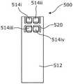
图5a-5d示出了在制造的各个阶段期间的本发明的加热器。首先参考图5a,加热器500包括基板512,基板512具有形成在基板512的表面中的一系列凹口520。加热器500被配置为支撑以2x 2构造布置在基板512的一端的四个电阻加热器元件(图5a中未示出)。凹口520布置在围绕电阻元件部分中的每一个的区域中。并非所有凹口520都连结在一起,使得在一些凹口之间存在间隙,在该间隙中基板512具有其全厚度。这是为了避免在四个电阻元件部分的区域中过度削弱基板512。凹口520可以通过合适的烧蚀工艺、例如激光蚀刻或切割形成。Figures 5a-5d illustrate the heater of the present invention during various stages of manufacture. Referring first to FIG. 5a, the
图5b示出了图5a的基板,其中触点513i-513v的布置被支撑在基板512上。触点513i-513v已经使用丝网印刷工艺沉积。触点513i-513v中的每一个的第一端布置成在基板512的一端连接到电阻元件部分(图5b中未示出)。导体513iii被配置为公共接地连接并且被布置为在其第一端连接到电阻元件部分中的每一个。导体513iii布置在触点513i-513v和电阻加热器元件的中间,因为这是由此它可以连接到电阻元件部分中的每一个的最方便的布置。触点513i,513ii,513iv和513v布置成在其第一端连接到四个电阻元件部分的每一个中的相应一个。FIG. 5b shows the substrate of FIG. 5a with the arrangement of
触点513i-513v的第二端终止于基板512的与电阻加热器元件所在的端部相对的一端处的相应系列的触点焊盘513a-513e。触点焊盘513c被配置为可连接到公共接地或电源的负电位,使得电阻加热器元件中的每一个可经由导体513iii连接到接地电位。触点焊盘513a,513b,513d和513e被配置为可连接到电源,使得可以经由触点513i,513ii,513iv和513v中的一个和公共接地导体513iii在电阻元件部分中的每一个上产生电位差。The second ends of the
图5c示出了支撑四个电阻加热器元件514i-514iv的基板512。为清楚起见,省略了触点513i-513v。电阻加热器元件514i-514iv以2x 2图案布置在基板512的一端。电阻元件部分514i-514iv中的每一个通过凹口520的形成而被围绕。电阻元件部分514i-514iv已使用丝网印刷工艺沉积。Figure 5c shows a
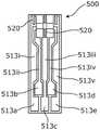
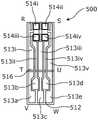
图5d示出了完全组装的加热器500,该加热器500包括基板512、触点513i-513v、电阻元件部分514i-514iv、阻挡层516和沉积在电阻元件部分514i-514iv中的每一个上的含有尼古丁的组合物(未示出)。电阻元件部分514i-514iv中的每一个已经连接在触点513i,513ii,513iv和513v中的相应的一个以及公共接地导体513iii上。当在电阻加热器元件514i-514iv中的一个上产生电位差时,电流流过电阻元件部分,从而启动电阻元件部分并使其温度升高。例如,向触点焊盘513a施加正电位并向触点焊盘513c施加接地或负电位来启动电阻加热器元件514i并使其产生热量。因此,电阻元件部分514i-514iv中的每一个可通过向触点焊盘513a,513b,513d和513e中的任何一个施加正电位并且向触点焊盘513c施加接地电位而被独立地启动。Figure 5d shows a fully assembled
阻挡层516在电阻元件部分514i-514iv和触点513i-513v的一部分上提供密封。阻挡层516在加热器500的由图5d中的点RSTU表示的区域上延伸。加热器的由点TUVW表示的区域未被阻挡层覆盖,因此不会使触点焊盘513a-513e绝缘,并允许它们与电源形成电连接。
含有尼古丁的组合物(未示出)沉积在电阻元件部分514i-514iv中的每一个上方的阻挡层516的顶部上。该组合物总共含有0.5mg尼古丁(浓度为40%)。已使用丝网印刷工艺沉积该组合物,但是技术人员将理解,可以使用其他的沉积方法。沉积在电阻元件部分514i-514iv中的每一个上面的含有尼古丁的组合物的量可以包括每次吸入的尼古丁的单个或多个剂量。A nicotine-containing composition (not shown) is deposited on top of
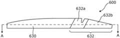
图6示出了根据本发明的吸入装置600,该吸入装置600包括主体部分630和吸嘴632。吸嘴632可释放地附接到主体部分630。此外,吸嘴632由单独的第一部分632a和第二部分632b形成,所述第一部分632a和第二部分632b在制造过程中被组装。然而,技术人员将理解,吸入装置600也可以由单件、例如单个管形成。FIG. 6 shows an
图7a示出了处于分解形式的吸嘴632。第一吸嘴部分632a具有用于接收图5d的加热器500的狭槽(未示出)。在制造期间,加热器500被插设到第一吸嘴部分632a的狭槽或凹槽中,并通过将第二吸嘴部分632b附接到第一吸嘴部分632a而被保持就位。第二吸嘴部分632b通过第二吸嘴部分632b任一侧的卡扣配合连接器634附接到第一吸嘴部分632a。Figure 7a shows the
图7b示出了处于组装形式的吸嘴632。加热器500被牢固地保持在吸嘴632内。如上所述,加热器500包括沉积在电阻元件部分上的含有尼古丁的组合物,因此吸嘴62包括可释放地连接到吸入装置600的主体部分630的可更换的消耗品。Figure 7b shows the
图8示出了沿图6中的线AA穿过吸入装置600的横截面。包含加热器500的吸嘴632连接到主体部分630。主体部分630的与吸嘴632连接的端部包括多个触点引脚636,该触点引脚636布置成与加热器500的触点焊盘513a-513e中的相应的一个形成电接触。FIG. 8 shows a cross-section through the
主体部分具有容纳电源(未示出)的第一内部空间638和包含用于控制电阻元件部分514的电启动的控制单元(未示出)的第二内部空间。触点引脚636经由控制单元连接到电源。按钮648也设置在主体部分630上,使得使用者能够启动加热器500。或者,技术人员将理解,可以使用响应于使用者吸入的传感器来启动加热器。The body portion has a first
吸嘴632具有通道642,当加热器500安装在吸嘴632中时,通道642覆盖在电阻元件部分514上。通道642与布置在主体部分630上的空气入口(未示出)和吸嘴632的空气出口644流体连通。收缩部646紧接在电阻元件部分514之前布置在通道642中,以使气流加速并在通道的该区域中提供压力下降。这有助于气雾化组合物在气流中的夹带。The
图6至图8的装置600被配置为高度精确并且符合人类药品条例的要求,因此这种装置适合用于尼古丁替代治疗。The
在使用中,使用者将其嘴唇密封在吸入装置600的吸嘴632周围并吸气。空气被抽吸到空气入口中,穿过通道642,并且在通过空气出口644离开吸入装置之前在电阻元件部分514的区域中流过加热器500上方。在吸气的同时,使用者按下按钮648以启动加热器500。取决于待输送的剂量,控制单元将通过引导电流通过这些电阻元件部分514来启动电阻元件部分514中的一个或多个,从而使它们产生热量。沉积在相应的一个或多个电阻元件部分上面的组合物的至少一部分被蒸发并在加热器500上面形成气雾化组合物,该组合物被夹带在移动的气流中。由于该组合物与加热器直接传导性接触,因此与通常被加热至约300℃的传统芯丝加热器相比,可在更低的温度、即140℃下实现所需量的组合物的气雾化。然后,使用者通过出口644吸入气雾化组合物。然后该装置重置以准备下一次吸入。In use, the user seals his lips around the
现在参考图9a和图9b,吸入装置600被示出为具有布置在主体部分630的顶表面中的空气入口650。空气入口650与吸入装置600的中心纵向轴线横向间隔开并且位于吸嘴632附接到主体部分630的区域中。图9b示出了沿图9a中的线B-B穿过吸入装置900的横截面图。空气入口650与吸嘴632流体连通,并且空气经由出口702(其一部分在图9b中示出)离开吸入装置600。气流通道从主体部分630上的空气入口650通向吸嘴632的出口702。气流通道的穿过吸嘴632的主要部分在图9b中不可见,因为它更靠近装置的中心纵向轴线地穿过(即在图10a中的线G-G的区域中)。Referring now to FIGS. 9 a and 9 b , the
参见图10a,其示出了单独的、即从主体部分630卸下的吸嘴632的平面图。图9b示出了沿图10a中的线G-G穿过吸嘴的横截面图。空气经由吸嘴632后部的开口720进入吸嘴632,该开口720与空气入口650(参见图9a和图9b)流体连通。空气经由封闭的气流通道或流体通路穿过吸嘴632流到出口702。穿过气流通道的气流在图10b中由虚线722a和722b表示。Referring to Figure 10a, a plan view of the
加热器703在吸嘴632内部布置于气流通道内。在加热器703附近,气流通道包括第一气流通道部分724a和第二气流通道部分724b。第一气流通道部分724a布置成引导气流的一部分(由虚线722a表示)通过且位于加热器703的第一面向上的表面703a及其电阻元件部分705上面。电阻元件部分705在加热器703的下游端位于吸嘴632的出口702附近或靠近吸嘴632的出口702。第二气流通道部分724b布置成引导气流的一部分(由虚线722b表示)通过且位于加热器703的第二面向下的表面703b下方。第一气流通道部分724a的上表面和第二气流通道部分724b的下表面是平坦的,以促使层流气流通过电阻元件部分705。The
加热器703支撑在导轨726上,导轨726平行于吸嘴的纵向轴线行进,并将加热器保持在气流通道内的中心区域,使得空气可以在加热器703的上面和下面流动。突起728a和728b分别从第一气流通道部分724a的上表面和第二气流通道部分724b的下表面延伸,并在加热器703的上游端与其接触,以帮助将加热器703保持在吸嘴632内的适当位置。突起728a和728b中的每一个具有穿过其的收缩孔或通道限制部(未在图10b中示出,参见图10c)。收缩孔的目的是通过限制突起728a和728b的区域中的气流来增加吸入阻力,并为传统烟草产品的吸食者提供对吸入装置600的更逼真的感觉。突起728a和728b位于电阻加热器元件705的足够上游,使得离开收缩孔的湍流空气在其流过电阻加热器元件705时具有空间以返回到层流流动。层流流动有助于阻止气雾化组合物到达气流通道的表面,因为气雾化组合物倾向于流过夹带有流线型气流的装置。The
图10c示出了吸嘴632的后视图,即在图10a中的箭头H的方向上的视图。吸嘴632具有将气流通道分成两部分的中心垂直分隔壁730。位于分隔壁730左侧的吸嘴632的部分基本上是位于分隔壁730右侧的吸嘴632的部分的镜像。吸嘴632的左手部分重复位于分隔壁730的右侧的吸嘴632的特征。Figure 10c shows a rear view of the
从图10c中可以看出,突起728a和728b接触加热器703以帮助将其保持在吸嘴632内的适当位置。突起728a和728b中的每一个具有穿过其的收缩孔732。收缩孔的形状是半圆形的,但是可以使用任何合适的形状。收缩孔732的尺寸或直径小于它们所处的气流通道的尺寸,以便如上所述地在突起728a和728b的区域中限制气流。As can be seen in Figure 10c, protrusions 728a and
在使用中,使用者将吸嘴632放入其嘴中并通过吸入装置600吸气。空气通过空气入口650流入并通过气流通道流向吸嘴632的出口650。可以设置传感器(未示出)以检测气流通道内的压力下降并向控制电路发送信号以加热或启动电阻加热器元件705。然而,技术人员将理解,由使用者按压的按钮(例如,图8中的648)可以用于代替传感器来启动电阻加热器元件705。一旦被启动,来自电阻加热器元件705的热量就被传递到覆盖电阻加热器元件705的组合物。组合物中的至少一部分蒸发以形成气雾化组合物,该气雾化组合物被夹带在流过加热器703的上部第一表面703a的气流中并被使用者吸入。In use, the user places the
由于电阻加热器元件705在加热器703的下游端位于出口702附近或靠近出口702,因此没有足够的时间和/或足够的气流通道长度或表面积来形成冷凝。因此,更大比例的含有尼古丁的组合物到达使用者。此外,这种布置阻止了吸嘴632内的冷凝液滴的形成,如果使用者吸入该冷凝液滴则会不愉快。Because the
在所述实施例中,气流不仅经过加热器703的上表面,还流过气流通道的位于加热器703下面的部分、即第二气流通道部分724b。发明人已经发现,下部第二气流通道部分724b可有助于阻止气雾化组合物在基板的下表面和吸嘴上的冷凝。In the described embodiment, the airflow not only passes through the upper surface of the
当使用者吸气时,空气必须通过收缩孔732被吸入。如上所述,这通过限制气流增加了吸入阻力,并为传统烟草产品的吸食者提供对吸入装置100的更逼真的感觉。收缩孔732位于上部第一气流通道部分724a和下部第二气流通道部分724b两者中,使得上部和下部气流被均等地限制,即两股气流以大致相同的速度和质量流速行进。这有助于空气顺畅地流过装置,从而进一步阻止了冷凝的形成。When the user inhales, air must be drawn in through the
各种修改对于本领域技术人员来说是显而易见的。例如,电阻元件部分、触点和组合物可以通过除丝网印刷之外的工艺沉积,例如通过喷墨打印或3D打印。另外,包括组合物的粒料可以由加热器支撑或附接到加热器。在施加热量后,粒料熔化并释放气雾化的组合物。Various modifications will be apparent to those skilled in the art. For example, resistive element portions, contacts and compositions can be deposited by processes other than screen printing, such as by ink jet printing or 3D printing. Additionally, the pellets comprising the composition may be supported by or attached to the heater. Upon application of heat, the pellets melt and release the aerosolized composition.
Claims (17)
Translated fromChineseApplications Claiming Priority (7)
| Application Number | Priority Date | Filing Date | Title |
|---|---|---|---|
| GB1704167.4 | 2017-03-16 | ||
| GBGB1704167.4AGB201704167D0 (en) | 2017-03-16 | 2017-03-16 | Heater and method |
| GBGB1708472.4AGB201708472D0 (en) | 2017-05-26 | 2017-05-26 | Inhalation device |
| GB1708472.4 | 2017-05-26 | ||
| GB1709864.1 | 2017-06-20 | ||
| GBGB1709864.1AGB201709864D0 (en) | 2017-06-20 | 2017-06-20 | Heater and method |
| PCT/EP2018/056429WO2018167166A1 (en) | 2017-03-16 | 2018-03-14 | A mouthpiece and heater assembly for an inhalation device |
Publications (2)
| Publication Number | Publication Date |
|---|---|
| CN110536614A CN110536614A (en) | 2019-12-03 |
| CN110536614Btrue CN110536614B (en) | 2022-06-21 |
Family
ID=63522890
Family Applications (1)
| Application Number | Title | Priority Date | Filing Date |
|---|---|---|---|
| CN201880018341.8AActiveCN110536614B (en) | 2017-03-16 | 2018-03-14 | Nozzle and heater assembly for inhalation device |
Country Status (14)
| Country | Link |
|---|---|
| US (1) | US10952467B2 (en) |
| EP (1) | EP3595467B1 (en) |
| JP (1) | JP7069489B2 (en) |
| KR (1) | KR102646017B1 (en) |
| CN (1) | CN110536614B (en) |
| AU (1) | AU2018234083B2 (en) |
| CA (1) | CA3056003A1 (en) |
| ES (1) | ES2884749T3 (en) |
| IL (1) | IL269098B (en) |
| PL (1) | PL3595467T3 (en) |
| RU (1) | RU2753944C2 (en) |
| SG (1) | SG11201908137SA (en) |
| WO (1) | WO2018167166A1 (en) |
| ZA (1) | ZA201905818B (en) |
Families Citing this family (27)
| Publication number | Priority date | Publication date | Assignee | Title |
|---|---|---|---|---|
| US20170215478A1 (en) | 2016-01-28 | 2017-08-03 | Stratos Product Development Llc | Vapor delivery systems and methods |
| CN110536614B (en)* | 2017-03-16 | 2022-06-21 | 万特斯医疗有限公司 | Nozzle and heater assembly for inhalation device |
| US12171261B2 (en) | 2018-10-12 | 2024-12-24 | Rai Strategic Holdings, Inc. | Vaporization system |
| US10791767B2 (en) | 2018-10-12 | 2020-10-06 | Rai Strategic Holdings, Inc. | Connectors for forming electrical and mechanical connections between interchangeable units in an aerosol delivery system |
| US12342860B2 (en) | 2018-10-12 | 2025-07-01 | Rai Strategic Holdings, Inc. | Heater and liquid transport for an aerosol delivery system |
| US11291249B2 (en) | 2018-10-12 | 2022-04-05 | Rai Strategic Holdings, Inc. | Aerosol delivery device with visible indicator |
| UA128068C2 (en)* | 2018-10-12 | 2024-03-27 | Джейті Інтернешнл С.А. | Aerosol generation device, and heating chamber therefor |
| US11502466B2 (en) | 2018-10-12 | 2022-11-15 | Rai Strategic Holdings, Inc. | Aerosol delivery device with improved connectivity, airflow, and aerosol paths |
| US11678700B2 (en) | 2018-10-12 | 2023-06-20 | Rai Strategic Holdings, Inc. | Aerosol delivery device with visible indicator |
| US11974603B2 (en) | 2018-10-12 | 2024-05-07 | Rai Strategic Holdings, Inc. | Aerosol delivery device with visible indicator |
| US12232526B2 (en) | 2018-10-12 | 2025-02-25 | Rai Strategic Holdings, Inc. | Connectors for forming electrical and mechanical connections between interchangeable units in an aerosol delivery system |
| US10939702B2 (en) | 2018-10-12 | 2021-03-09 | Rai Strategic Holdings, Inc. | Connectors for forming electrical and mechanical connections between interchangeable units in an aerosol delivery system |
| US11156766B2 (en) | 2018-11-19 | 2021-10-26 | Rai Strategic Holdings, Inc. | Aerosol delivery device |
| US11614720B2 (en) | 2018-11-19 | 2023-03-28 | Rai Strategic Holdings, Inc. | Temperature control in an aerosol delivery device |
| US11592793B2 (en) | 2018-11-19 | 2023-02-28 | Rai Strategic Holdings, Inc. | Power control for an aerosol delivery device |
| US12066654B2 (en) | 2018-11-19 | 2024-08-20 | Rai Strategic Holdings, Inc. | Charging control for an aerosol delivery device |
| US11372153B2 (en) | 2018-11-19 | 2022-06-28 | Rai Strategic Holdings, Inc. | Cartridge orientation for selection of a control function in a vaporization system |
| WO2020108974A1 (en)* | 2018-11-28 | 2020-06-04 | Philip Morris Products S.A. | Heater comprising a part manufactured by additive manufacturing |
| EP3836813B1 (en)* | 2019-05-06 | 2023-01-04 | Central Victory Limited HK | Flat heat element for microvaporizer |
| WO2020245338A1 (en)* | 2019-06-06 | 2020-12-10 | Philip Morris Products S.A. | Aerosol-generating device with separable venturi element |
| WO2022003802A1 (en)* | 2020-06-30 | 2022-01-06 | 日本たばこ産業株式会社 | Non-combustion type suction device |
| US11856986B2 (en) | 2020-10-19 | 2024-01-02 | Rai Strategic Holdings, Inc. | Customizable panel for aerosol delivery device |
| GB202100353D0 (en) | 2021-01-12 | 2021-02-24 | Ventus Medical Ltd | Aerosolizable nicoltine-containing formulations |
| EP4056217A1 (en)* | 2021-03-10 | 2022-09-14 | JT International SA | Aerosol generation device without aerosol leakage |
| US12144377B2 (en) | 2021-10-01 | 2024-11-19 | Rai Strategic Holdings, Inc. | Absorbent containing mouthpiece for aerosol delivery device |
| WO2024200713A1 (en)* | 2023-03-29 | 2024-10-03 | Nicoventures Trading Limited | Aerosol generator |
| WO2024243720A1 (en)* | 2023-05-26 | 2024-12-05 | Imperial Tobacco Limited | Aerosol generating apparatus |
Citations (4)
| Publication number | Priority date | Publication date | Assignee | Title |
|---|---|---|---|---|
| CN102389609A (en)* | 2011-06-29 | 2012-03-28 | 田中枢 | Portable heart disease first aid administration device |
| WO2016005533A1 (en)* | 2014-07-11 | 2016-01-14 | Philip Morris Products S.A. | Aerosol-forming cartridge comprising a tobacco-containing material |
| EP3020292A1 (en)* | 2014-11-14 | 2016-05-18 | Shenzhen First Union Technology Co., Ltd. | Atomizing device and electronic cigarette having same |
| CN106488720A (en)* | 2014-06-20 | 2017-03-08 | 宝洁公司 | Method of delivering a dose of a fluid composition from a microfluidic delivery cartridge |
Family Cites Families (8)
| Publication number | Priority date | Publication date | Assignee | Title |
|---|---|---|---|---|
| US20130255702A1 (en) | 2012-03-28 | 2013-10-03 | R.J. Reynolds Tobacco Company | Smoking article incorporating a conductive substrate |
| US8881737B2 (en)* | 2012-09-04 | 2014-11-11 | R.J. Reynolds Tobacco Company | Electronic smoking article comprising one or more microheaters |
| US10172387B2 (en) | 2013-08-28 | 2019-01-08 | Rai Strategic Holdings, Inc. | Carbon conductive substrate for electronic smoking article |
| WO2016005530A1 (en) | 2014-07-11 | 2016-01-14 | Philip Morris Products S.A. | Aerosol-forming cartridge comprising a liquid nicotine source |
| MX2017012644A (en) | 2015-04-07 | 2018-01-24 | Philip Morris Products Sa | Sachet of aerosol-forming substrate, method of manufacturing same, and aerosol-generating device for use with sachet. |
| WO2016172420A1 (en) | 2015-04-22 | 2016-10-27 | Altria Client Services Llc | Pod assembly, dispensing body, and e-vapor apparatus including the same |
| CN110536614B (en)* | 2017-03-16 | 2022-06-21 | 万特斯医疗有限公司 | Nozzle and heater assembly for inhalation device |
| GB201800500D0 (en)* | 2018-01-11 | 2018-02-28 | Project Paradise Ltd | A mouthpiece assmebly for an inhalation device including a replaceable substrate component,and a replaceable substrate component therefor |
- 2018
- 2018-03-14CNCN201880018341.8Apatent/CN110536614B/enactiveActive
- 2018-03-14EPEP18715501.5Apatent/EP3595467B1/enactiveActive
- 2018-03-14AUAU2018234083Apatent/AU2018234083B2/enactiveActive
- 2018-03-14SGSG11201908137Spatent/SG11201908137SA/enunknown
- 2018-03-14WOPCT/EP2018/056429patent/WO2018167166A1/ennot_activeCeased
- 2018-03-14USUS16/493,798patent/US10952467B2/enactiveActive
- 2018-03-14KRKR1020197030373Apatent/KR102646017B1/enactiveActive
- 2018-03-14ILIL269098Apatent/IL269098B/enunknown
- 2018-03-14JPJP2019571781Apatent/JP7069489B2/enactiveActive
- 2018-03-14ESES18715501Tpatent/ES2884749T3/enactiveActive
- 2018-03-14RURU2019132622Apatent/RU2753944C2/enactive
- 2018-03-14CACA3056003Apatent/CA3056003A1/enactivePending
- 2018-03-14PLPL18715501Tpatent/PL3595467T3/enunknown
- 2019
- 2019-09-03ZAZA2019/05818Apatent/ZA201905818B/enunknown
Patent Citations (4)
| Publication number | Priority date | Publication date | Assignee | Title |
|---|---|---|---|---|
| CN102389609A (en)* | 2011-06-29 | 2012-03-28 | 田中枢 | Portable heart disease first aid administration device |
| CN106488720A (en)* | 2014-06-20 | 2017-03-08 | 宝洁公司 | Method of delivering a dose of a fluid composition from a microfluidic delivery cartridge |
| WO2016005533A1 (en)* | 2014-07-11 | 2016-01-14 | Philip Morris Products S.A. | Aerosol-forming cartridge comprising a tobacco-containing material |
| EP3020292A1 (en)* | 2014-11-14 | 2016-05-18 | Shenzhen First Union Technology Co., Ltd. | Atomizing device and electronic cigarette having same |
Also Published As
| Publication number | Publication date |
|---|---|
| CA3056003A1 (en) | 2018-09-20 |
| RU2753944C2 (en) | 2021-08-24 |
| ES2884749T3 (en) | 2021-12-13 |
| JP2020509784A (en) | 2020-04-02 |
| EP3595467B1 (en) | 2021-05-19 |
| KR20190131059A (en) | 2019-11-25 |
| AU2018234083A1 (en) | 2019-09-26 |
| JP7069489B2 (en) | 2022-05-18 |
| RU2019132622A3 (en) | 2021-06-24 |
| PL3595467T3 (en) | 2021-11-22 |
| IL269098A (en) | 2019-11-28 |
| US20200128875A1 (en) | 2020-04-30 |
| AU2018234083B2 (en) | 2022-11-03 |
| ZA201905818B (en) | 2020-07-29 |
| IL269098B (en) | 2022-07-01 |
| CN110536614A (en) | 2019-12-03 |
| WO2018167166A1 (en) | 2018-09-20 |
| SG11201908137SA (en) | 2019-10-30 |
| EP3595467A1 (en) | 2020-01-22 |
| RU2019132622A (en) | 2021-04-16 |
| KR102646017B1 (en) | 2024-03-08 |
| BR112019018959A2 (en) | 2020-04-22 |
| US10952467B2 (en) | 2021-03-23 |
Similar Documents
| Publication | Publication Date | Title |
|---|---|---|
| CN110536614B (en) | Nozzle and heater assembly for inhalation device | |
| JP7493564B2 (en) | Aerosol delivery device comprising a microfluidic delivery component | |
| JP7648689B2 (en) | Aerosol generation system using the Venturi effect to deliver substrate to heater element | |
| CN111031817A (en) | Aerosol Delivery Devices and Related Methods | |
| EP3941285B1 (en) | Aerosol delivery system | |
| WO2019068441A1 (en) | Inhalation device and substrate | |
| BR112019018959B1 (en) | NOZZLE AND HEATER ASSEMBLY FOR AN INHALATION DEVICE AND INHALATION DEVICE | |
| KR20240053046A (en) | Aerosol-generating system having a mouthpiece with sensory medium |
Legal Events
| Date | Code | Title | Description |
|---|---|---|---|
| PB01 | Publication | ||
| PB01 | Publication | ||
| SE01 | Entry into force of request for substantive examination | ||
| SE01 | Entry into force of request for substantive examination | ||
| GR01 | Patent grant | ||
| GR01 | Patent grant |