CN110520055B - Device and method for measuring viscoelasticity of viscoelastic media - Google Patents
Device and method for measuring viscoelasticity of viscoelastic mediaDownload PDFInfo
- Publication number
- CN110520055B CN110520055BCN201880022597.6ACN201880022597ACN110520055BCN 110520055 BCN110520055 BCN 110520055BCN 201880022597 ACN201880022597 ACN 201880022597ACN 110520055 BCN110520055 BCN 110520055B
- Authority
- CN
- China
- Prior art keywords
- probe
- force
- contact
- ready signal
- measurement
- Prior art date
- Legal status (The legal status is an assumption and is not a legal conclusion. Google has not performed a legal analysis and makes no representation as to the accuracy of the status listed.)
- Active
Links
Images


Classifications
- A—HUMAN NECESSITIES
- A61—MEDICAL OR VETERINARY SCIENCE; HYGIENE
- A61B—DIAGNOSIS; SURGERY; IDENTIFICATION
- A61B8/00—Diagnosis using ultrasonic, sonic or infrasonic waves
- A61B8/48—Diagnostic techniques
- A61B8/485—Diagnostic techniques involving measuring strain or elastic properties
- A—HUMAN NECESSITIES
- A61—MEDICAL OR VETERINARY SCIENCE; HYGIENE
- A61B—DIAGNOSIS; SURGERY; IDENTIFICATION
- A61B8/00—Diagnosis using ultrasonic, sonic or infrasonic waves
- A61B8/08—Clinical applications
- A—HUMAN NECESSITIES
- A61—MEDICAL OR VETERINARY SCIENCE; HYGIENE
- A61B—DIAGNOSIS; SURGERY; IDENTIFICATION
- A61B8/00—Diagnosis using ultrasonic, sonic or infrasonic waves
- A61B8/08—Clinical applications
- A61B8/0833—Clinical applications involving detecting or locating foreign bodies or organic structures
- A—HUMAN NECESSITIES
- A61—MEDICAL OR VETERINARY SCIENCE; HYGIENE
- A61B—DIAGNOSIS; SURGERY; IDENTIFICATION
- A61B8/00—Diagnosis using ultrasonic, sonic or infrasonic waves
- A61B8/42—Details of probe positioning or probe attachment to the patient
- A61B8/4245—Details of probe positioning or probe attachment to the patient involving determining the position of the probe, e.g. with respect to an external reference frame or to the patient
- A61B8/4254—Details of probe positioning or probe attachment to the patient involving determining the position of the probe, e.g. with respect to an external reference frame or to the patient using sensors mounted on the probe
- A—HUMAN NECESSITIES
- A61—MEDICAL OR VETERINARY SCIENCE; HYGIENE
- A61B—DIAGNOSIS; SURGERY; IDENTIFICATION
- A61B8/00—Diagnosis using ultrasonic, sonic or infrasonic waves
- A61B8/42—Details of probe positioning or probe attachment to the patient
- A61B8/4272—Details of probe positioning or probe attachment to the patient involving the acoustic interface between the transducer and the tissue
- A61B8/429—Details of probe positioning or probe attachment to the patient involving the acoustic interface between the transducer and the tissue characterised by determining or monitoring the contact between the transducer and the tissue
- A—HUMAN NECESSITIES
- A61—MEDICAL OR VETERINARY SCIENCE; HYGIENE
- A61B—DIAGNOSIS; SURGERY; IDENTIFICATION
- A61B8/00—Diagnosis using ultrasonic, sonic or infrasonic waves
- A61B8/44—Constructional features of the ultrasonic, sonic or infrasonic diagnostic device
- A—HUMAN NECESSITIES
- A61—MEDICAL OR VETERINARY SCIENCE; HYGIENE
- A61B—DIAGNOSIS; SURGERY; IDENTIFICATION
- A61B8/00—Diagnosis using ultrasonic, sonic or infrasonic waves
- A61B8/44—Constructional features of the ultrasonic, sonic or infrasonic diagnostic device
- A61B8/4483—Constructional features of the ultrasonic, sonic or infrasonic diagnostic device characterised by features of the ultrasound transducer
- A61B8/4494—Constructional features of the ultrasonic, sonic or infrasonic diagnostic device characterised by features of the ultrasound transducer characterised by the arrangement of the transducer elements
- A—HUMAN NECESSITIES
- A61—MEDICAL OR VETERINARY SCIENCE; HYGIENE
- A61B—DIAGNOSIS; SURGERY; IDENTIFICATION
- A61B8/00—Diagnosis using ultrasonic, sonic or infrasonic waves
- A61B8/54—Control of the diagnostic device
- A61B8/543—Control of the diagnostic device involving acquisition triggered by a physiological signal
Landscapes
- Health & Medical Sciences (AREA)
- Life Sciences & Earth Sciences (AREA)
- Physics & Mathematics (AREA)
- Heart & Thoracic Surgery (AREA)
- Molecular Biology (AREA)
- Nuclear Medicine, Radiotherapy & Molecular Imaging (AREA)
- Pathology (AREA)
- Radiology & Medical Imaging (AREA)
- Engineering & Computer Science (AREA)
- Biomedical Technology (AREA)
- Veterinary Medicine (AREA)
- Medical Informatics (AREA)
- Biophysics (AREA)
- Surgery (AREA)
- Animal Behavior & Ethology (AREA)
- General Health & Medical Sciences (AREA)
- Public Health (AREA)
- Gynecology & Obstetrics (AREA)
- Acoustics & Sound (AREA)
- Physiology (AREA)
- Ultra Sonic Daignosis Equipment (AREA)
Abstract
Description
Translated fromChinese技术领域technical field
本发明涉及一种用于测量粘弹性介质(例如人体或动物器官)的粘弹性的装置。具体而言,本发明可用于测量肝脏的粘弹性,其允许对所述肝脏中存在的纤维化的量进行量化。本发明还涉及一种用于测量粘弹性介质的粘弹性的方法。The invention relates to a device for measuring the viscoelasticity of viscoelastic media, such as human or animal organs. In particular, the invention can be used to measure the viscoelasticity of the liver, which allows the quantification of the amount of fibrosis present in said liver. The invention also relates to a method for measuring the viscoelasticity of a viscoelastic medium.
背景技术Background technique
酒精性、病毒性或其他原因引起的慢性肝炎,具有纤维化效果,这对于评估进而确定治疗肝炎的最佳时间而言是很重要的。Chronic hepatitis, alcoholic, viral, or otherwise, has a fibrotic effect, which is important to evaluate and determine the optimal time to treat hepatitis.
用于测量肝脏硬度的一种最可靠和有效的技术是瞬时弹性成像(例如,参见《Ultrasound in Med.And Biol.》41,5,2015中公布的由G.Ferraioli等人所著的“WFUMBguidelines and recommendations for clinical use of ultrasound elastographypart 3:liver(WFUMB超声弹性成像临床使用指南和建议第3部分:肝脏)”)。One of the most reliable and valid techniques for measuring liver stiffness is transient elastography (see for example "WFUMB guidelines by G. Ferraioli et al. published in Ultrasound in Med. And Biol." 41, 5, 2015 and recommendations for clinical use of ultrasound elastography part 3: liver (WFUMB Ultrasound Elastography Clinical Use Guidelines and Recommendations Part 3: Liver)").
申请人已经研发并商业化了一种称为
在应用VCTE时,肝脏硬度的测量依赖于测量瞬时剪切波在组织内的传播速度。In the application of VCTE, the measurement of liver stiffness relies on measuring the propagation velocity of transient shear waves in the tissue.
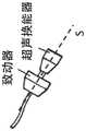
为了执行上述测量,已经研发了一种特定的探针。所述探针包括至少一个电动致动器和安装在所述探针尖端的至少一个超声波换能器。In order to perform the above-mentioned measurements, a specific probe has been developed. The probe includes at least one electric actuator and at least one ultrasonic transducer mounted at the tip of the probe.
例如,在
得益于
此外,
目前可用的VCTE探针中的相关问题是在将瞬时剪切波施加于待检查组织时的探针尖端的实际运动的控制。例如,当施加剪切波时,探针的反冲力可被增加至尖端的运动,且所施加的脉冲会变形。该问题涉及操作者的手的反冲力、以及操作者在保持探针抵靠病人身体时必须施加的力的控制:为了正确使用根据现有技术的VCTE探针,需要熟练或有资质的操作者。A related problem in currently available VCTE probes is the control of the actual motion of the probe tip when a transient shear wave is applied to the tissue to be examined. For example, when a shear wave is applied, the recoil force of the probe can be added to the motion of the tip and the applied pulse deformed. The problem concerns the recoil force of the operator's hand, and the control of the force the operator has to apply when holding the probe against the patient's body: for the correct use of VCTE probes according to the prior art, a skilled or qualified operator is required .
如果不控制探针的反冲力,就不能知道探针尖端相对于病人身体的实际运动。测量可能依赖于操作者在产生剪切波期间所施加的力。Without controlling the recoil of the probe, the actual motion of the probe tip relative to the patient's body cannot be known. Measurements may depend on the force applied by the operator during shear wave generation.
专利申请US8333704B2(2010年12月18日由Anthony等人申请的“Hand-heldforce-controlled ultrasound probe(手持式力受控超声探头)”)和US2012/0316407A1(2012年6月12日由Anthony等人申请的“Sonographer fatigue monitoring(超声仪疲劳监测)”)中公开了具有线性致动器和力传感器的超声波探针。图1b显示了文献US8333704所描述的装置。根据这些文献,超声波换能器被电动致动器移动,以便控制施加于待分析组织的力。基于力传感器提供并用作反馈信号的信号,控制超声波换能器的运动。Patent applications US8333704B2 ("Hand-heldforce-controlled ultrasonic probe (hand-held force-controlled ultrasonic probe)" applied by Anthony et al. on December 18, 2010) and US2012/0316407A1 (on June 12, 2012 by Anthony et al. Application "Sonographer fatigue monitoring") discloses ultrasonic probes with linear actuators and force sensors. Figure 1b shows the device described in document US8333704. According to these documents, the ultrasound transducer is moved by an electric actuator in order to control the force applied to the tissue to be analyzed. The movement of the ultrasonic transducer is controlled based on the signal provided by the force sensor and used as a feedback signal.
这些文献解决了在超声波测量期间施加恒定或时间相关的力的问题,但这些公开的技术方案具有多个缺陷。These documents address the problem of applying a constant or time-dependent force during ultrasonic measurements, but these disclosed solutions suffer from several drawbacks.
例如,现有技术中所描述的这些装置包括外部机械可移动部件:如图1b中的箭头所示,超声波换能器相对于探针外壳移动。多个缺陷与该外部可移动部件相关,例如需要频率校准操作。For example, the devices described in the prior art comprise external mechanically movable parts: the ultrasound transducer moves relative to the probe housing, as indicated by the arrow in Fig. 1b. Several deficiencies are associated with this external movable part, such as the need for frequency calibration operations.
由D.Mellema等人所著的文献“Probe Oscillation Shear Elastography(PEOSE):A high Frame-Rate Method for Two-dimensional ultrasound shear waveelastography(探针振荡剪切弹性成像(PEOSE):二维超声剪切波弹性成像的高帧频方法)”(公布于IEEE Transaction on medical imaging,2016年第35卷第9期)中描述了现有技术中所描述的另一个方案。该方案中描述了用于连续波弹性成像的探针。该方案不适用于对组织施加瞬时剪切脉冲,仅适用于连续波剪切波振荡。此外,该弹性成像探针由两个分离的组件构成,这对于活体内(in-vivo)的应用而言是严重的缺陷。例如,由于存在多个部分,因此上述探针是难以操作的。The literature "Probe Oscillation Shear Elastography (PEOSE): A high Frame-Rate Method for Two-dimensional ultrasonic shear wave elastography (probe oscillation shear elastography (PEOSE): two-dimensional ultrasonic shear wave Another approach described in the prior art is described in "High Frame Rate Methods for Elastography" (published in IEEE Transactions on medical imaging, Vol. 35, No. 9, 2016). A probe for continuous wave elastography is described in this protocol. This protocol is not suitable for applying transient shear pulses to tissue, only for continuous wave shear wave oscillations. Furthermore, the elastography probe consists of two separate components, which is a serious drawback for in-vivo applications. For example, the probes described above are difficult to manipulate due to the presence of multiple parts.
此外,根据操作者的不同,当将超声波换能器放在病人身体上时,难以控制施加的力。因此,该装置不能在不考虑操作者的情况下准确且可重现地进行测量。Furthermore, depending on the operator, it can be difficult to control the force applied when placing the ultrasound transducer on the patient's body. Therefore, the device cannot perform measurements accurately and reproducibly regardless of the operator.
此外,如果在病人身体上施加的力过大,装置的电动致动器可能被损坏。Furthermore, the electric actuators of the device may be damaged if excessive force is exerted on the patient's body.
最后,由传感器的超声波换能器传递给病人的声能量可能会很高,非必要的使用可能会导致对病人的损伤、电气故障以及超声波换能器的过早损坏。Finally, the acoustic energy delivered to the patient by the transducer's ultrasonic transducer can be high, and unnecessary use can lead to injury to the patient, electrical failure, and premature failure of the ultrasonic transducer.
发明内容Contents of the invention
本发明的一个方面在于解决上述缺陷的装置。因此,本发明的一个方面在于准确且可重现地测量粘弹性介质的粘弹性的装置,从而限制病人的健康风险,并延长装置的寿命。One aspect of the present invention is an arrangement that addresses the above-mentioned drawbacks. Accordingly, one aspect of the present invention resides in a device for accurately and reproducibly measuring the viscoelasticity of a viscoelastic medium, thereby limiting health risks to the patient and prolonging the lifetime of the device.
为了实现该目标,本发明的第一方面在于测量粘弹性介质的粘弹性的装置,所述介质在遭受超声波脉冲后具有超声波信号,所述装置包括:In order to achieve this aim, a first aspect of the invention consists in a device for measuring the viscoelasticity of a viscoelastic medium, said medium having an ultrasonic signal after being subjected to an ultrasonic pulse, said device comprising:
-用于瞬时弹性成像的探针,包括:- Probes for transient elastography, including:
·探针外壳;· Probe housing;
·具有对称轴的至少一个超声波换能器;· at least one ultrasonic transducer with an axis of symmetry;
·至少一个振动器,所述振动器位于探针外壳内部;· at least one vibrator located inside the probe housing;
·力传感器,所述力传感器被构造为测量由所述探针对所述待测量的粘弹性介质施加的力;a force sensor configured to measure the force exerted by the probe on the viscoelastic medium to be measured;
-信号生成器;- signal generator;
所述装置的特征在于:The device is characterized by:
·所述振动器被布置为引起所述探针外壳沿预定轴的移动,所述预定轴是所述超声波换能器的所述对称轴;- said vibrator is arranged to cause movement of said probe housing along a predetermined axis, said predetermined axis being said axis of symmetry of said ultrasonic transducer;
·所述超声波换能器固定在所述探针外壳上,使得所述超声波换能器不相对于所述探针外壳运动;the ultrasonic transducer is fixed on the probe housing such that the ultrasonic transducer does not move relative to the probe housing;
·所述信号生成器被构造并设置为当所述探针的所述超声波换能器接触待测量的粘弹性介质时发出接触就绪信号,当所述超声波探针在所述粘弹性介质上施加的力大于最小接触力阈值时,所述信号生成器设定接触就绪信号。The signal generator is constructed and arranged to emit a contact ready signal when the ultrasonic transducer of the probe contacts the viscoelastic medium to be measured, when the ultrasonic probe is applied on the viscoelastic medium The signal generator sets a contact ready signal when the force is greater than the minimum contact force threshold.
探针外壳是VCTE探针的封套,所述封套包含振动器或电动致动器。所述探针外壳也可以包含其他元件,例如位置传感器、逻辑电路或连接装置,以用于储存数据或与计算机或其他电子装置交换数据。超声波换能器是适用于发射和接收超声波的装置。可以用一个换能器或换能器阵列来形成超声波换能器,例如形成线性检测器。The probe housing is the envelope of the VCTE probe that contains the vibrator or electric actuator. The probe housing may also contain other components, such as position sensors, logic circuits or connections for storing or exchanging data with a computer or other electronic devices. An ultrasonic transducer is a device suitable for transmitting and receiving ultrasonic waves. An ultrasound transducer may be formed with one transducer or an array of transducers, for example to form a linear detector.
超声波换能器的对称轴是所述换能器的几何对称轴。所述超声波换能器的对称轴也是所述换能器发射超声波的所沿的方向。所述换能器的对称轴对应于所述换能器发射的超声波短脉冲的传播方向。The axis of symmetry of an ultrasound transducer is the geometric axis of symmetry of the transducer. The axis of symmetry of the ultrasonic transducer is also the direction along which the transducer emits ultrasonic waves. The axis of symmetry of the transducer corresponds to the direction of propagation of short ultrasonic pulses emitted by the transducer.
根据本发明,所述超声波换能器在运动固定在所述探针外壳上,这表示所述超声波换能器相对于所述探针外壳没有相对运动。According to the invention, the ultrasound transducer is kinematically fixed to the probe housing, which means that there is no relative movement of the ultrasound transducer with respect to the probe housing.
所述超声波换能器的一个端部可以固定在所述探针外壳的端部上。所述超声波换能器的另一个端部可以自由振动,以向待分析的介质发送超声波。One end of the ultrasonic transducer may be fixed to the end of the probe housing. The other end of the ultrasonic transducer can vibrate freely to transmit ultrasonic waves to the medium to be analyzed.
可替代的是,所述超声波换能器可以利用探针尖端而附装至所述探针外壳。当探针尖端存在时,所述探针尖端可具有固定至所述探针外壳的端部的端部以及固定至所述超声波换能器的另一个端部。Alternatively, the ultrasonic transducer may be attached to the probe housing with a probe tip. When a probe tip is present, the probe tip may have an end fixed to an end of the probe housing and another end fixed to the ultrasonic transducer.
下文所给出的本发明的说明支持当超声波换能器直接固定至探针外壳时以及当超声波换能器通过探针尖端固定至探针外壳时的两种情况。这两种配置仅作为示例性实施方式给出,其他配置也是可以的。The description of the invention given below supports both cases when the ultrasound transducer is fixed directly to the probe housing and when the ultrasound transducer is fixed to the probe housing through the probe tip. These two configurations are given as exemplary embodiments only, and other configurations are possible.
振动器是适用于移动探针外壳内的物体的装置。例如,振动器可以以1至5000Hz之间的某个频率使物体振荡。A vibrator is a device suitable for moving objects within a probe housing. For example, a vibrator can vibrate an object at a frequency somewhere between 1 and 5000 Hz.
由于探针自身的移动是因探针外壳内的物体的移动而产生的,因此根据本发明的探针可以视为惯性探针。根据本发明的探针不包括外部机械可移动部件。A probe according to the invention may be considered an inertial probe since the movement of the probe itself is caused by the movement of objects within the probe housing. The probe according to the invention comprises no external mechanically movable parts.
根据本发明的探针是瞬时弹性成像探针。这表示其适用于对组织施加瞬时剪切波以进行检测,并通过以较高的重复率发送超声波分析剪切波的传播。The probes according to the invention are transient elastography probes. This means that it is suitable for applying transient shear waves to tissue for detection and analyzing the propagation of shear waves by sending ultrasound at a high repetition rate.
由探针的移动在组织内产生剪切波,所述探针的移动使超声波换能器推压组织。通过对介质表面施加低频脉冲,生成剪切波。例如,所述脉冲可具有位于在1Hz至5000Hz之间的中心频率f处的一个周期的正弦曲线形状。Shear waves are generated within the tissue by movement of the probe, which causes the ultrasound transducer to push against the tissue. Shear waves are generated by applying low frequency pulses to the surface of the medium. For example, the pulse may have a one-period sinusoidal shape at a center frequency f between 1 Hz and 5000 Hz.
施加至组织的低频脉冲的持续周期在1/2F至20/f之间。The duration of the low frequency pulses applied to the tissue is between 1/2F and 20/f.
以100Hz至100*103Hz之间的重复率发射超声波短脉冲。Short pulses of ultrasound are emitted at a repetition rate between 100 Hz and 100*103 Hz.
通过在介质内以较高的重复率发送超声波脉冲或束,并通过检测背向散射的超声波信号,来检测剪切波的传播。实际上,组织包含不均匀性或能够部分反射超声波脉冲的粒子。Shear wave propagation is detected by sending ultrasonic pulses or beams at a high repetition rate within the medium and by detecting the backscattered ultrasonic signal. In reality, tissue contains inhomogeneities or particles that partially reflect ultrasound pulses.
通过记录和分析后续的背向散射信号,可以计算组织因剪切波的传播而引起的位移。然后,就能推导出剪切波的性质。例如,剪切波的传播速度与粘弹性介质的硬度直接相关。By recording and analyzing the subsequent backscatter signal, the displacement of the tissue due to the propagation of the shear wave can be calculated. Then, the properties of the shear waves can be deduced. For example, the speed of propagation of shear waves is directly related to the stiffness of the viscoelastic medium.
本发明所描述的探针的优点在于控制超声波换能器的实际运动。实际上,超声波换能器被固定至探针外壳,在超声波换能器和探针外壳之间不存在相互运动。这样就可以监控探针外壳的运动,其对应于超声波换能器的实际运动。为了控制组织内所产生的瞬时剪切波的形状,测量超声波换能器的实际运动是很重要的。例如,可以利用安装在探针自身上的加速度计测量探针的运动。An advantage of the probe described in the present invention is the control of the actual movement of the ultrasonic transducer. In fact, the ultrasound transducer is fixed to the probe housing, there is no mutual movement between the ultrasound transducer and the probe housing. This makes it possible to monitor the movement of the probe housing, which corresponds to the actual movement of the ultrasound transducer. In order to control the shape of the transient shear waves generated within the tissue, it is important to measure the actual motion of the ultrasound transducer. For example, the movement of the probe can be measured using an accelerometer mounted on the probe itself.
换言之,与传统的VCTE探针中的做法相反的是,本发明在地球参照系中测量超声波换能器的运动。实际上,在根据现有技术的VCTE探针中,是在探针外壳的参照系中测量超声波换能器的运动,且仅测量超声波换能器相对于探针外壳的相对运动。In other words, the present invention measures the motion of the ultrasound transducer in the Earth's reference frame, contrary to what is done in conventional VCTE probes. Indeed, in VCTE probes according to the prior art, the movement of the ultrasound transducer is measured in the frame of reference of the probe housing, and only the relative movement of the ultrasound transducer with respect to the probe housing is measured.
具体而言,通过控制回路并将探针外壳的运动用作反馈信号,可以确定探针外壳内部由振动器致使的物体运动。这样就可以在施加剪切波期间对操作者的手的运动直接进行补偿。Specifically, by controlling the loop and using the motion of the probe housing as a feedback signal, the motion of the object inside the probe housing caused by the vibrator can be determined. This allows for direct compensation of the operator's hand motion during application of the shear wave.
操作者不需要施加精确的力以补偿探针的反冲力。结果,对于探针的操作者而言,测量粘弹性介质的硬度变得简单。此外,硬度测量值更具重现性。The operator does not need to apply precise force to compensate for probe recoil. As a result, measuring the hardness of viscoelastic media becomes simple for the operator of the probe. Additionally, hardness measurements are more reproducible.
根据现有技术中的做法,仅测量超声波换能器相对于探针外壳的相对运动,其不能将探针的反冲力考虑在内。结果,即使尖端的相对运动遵循正弦曲线轨迹,施加至病人身体的有效低频脉冲也可能因探针的反冲力而呈不同的形状。According to the practice in the prior art, only the relative movement of the ultrasonic transducer with respect to the probe housing is measured, which cannot take into account the recoil force of the probe. As a result, even though the relative motion of the tips follows a sinusoidal trajectory, the effective low frequency pulses applied to the patient's body may be shaped differently due to the recoil force of the probe.
根据本发明,与病人身体接触的超声波换能器与探针外壳一起运动。检测探针外壳的运动等效于检测探针尖端的运动。探针外壳的运动被用作用于振动器的反馈。实际上,振动器的振荡振幅可以被调整以获得与病人身体接触的探针尖端的期望运动。此外,根据本发明的探针中没有外部可移动部件,从而不需要频繁的机械校准。According to the invention, the ultrasonic transducer which is in contact with the patient's body moves together with the probe housing. Detecting the movement of the probe housing is equivalent to detecting the movement of the probe tip. The movement of the probe housing is used as feedback for the vibrator. Indeed, the oscillation amplitude of the vibrator can be adjusted to obtain the desired movement of the probe tip in contact with the patient's body. Furthermore, there are no external movable parts in the probe according to the invention, so that frequent mechanical calibration is not required.
由于本发明的装置包括发出接触就绪信号的信号生成器,操作者不激活超声波信号直至信号生成器发出接触就绪信号。因此,所述装置确保了超声波换能器所发射的超声波信号功率仅在必要时被使用,且对于病人而言尽可能低。Since the device of the present invention includes a signal generator that emits a contact-ready signal, the operator does not activate the ultrasonic signal until the signal generator emits a contact-ready signal. Thus, the device ensures that the power of the ultrasound signal emitted by the ultrasound transducer is used only when necessary and as low as possible for the patient.
信号生成器基于超声波换能器和病人身体之间的接触力发出所述接触就绪信号。可以用探针上设置的力传感器测量接触力。仅在测量的接触力满足预定条件时才发出接触就绪信号。例如,测量的接触力必须大于最小接触力阈值。当满足上述条件时,探针被认为与待测量的粘弹性介质接触。可替代的是,可以仅当接触力在最小接触力阈值和最大接触力阈值之间时发出接触就绪信号。A signal generator emits the contact ready signal based on the contact force between the ultrasound transducer and the patient's body. The contact force can be measured with a force sensor provided on the probe. The contact ready signal is issued only when the measured contact force meets predetermined conditions. For example, the measured contact force must be greater than the minimum contact force threshold. When the above conditions are met, the probe is considered to be in contact with the viscoelastic medium to be measured. Alternatively, the contact ready signal may only be issued when the contact force is between a minimum contact force threshold and a maximum contact force threshold.
此外,考虑到仅当超声波探针的换能器接触待测量的粘弹性介质时接触就绪信号才被设定,因此装置的测量是精确而可重现的,与装置的操作者无关。实际上,对于现有技术的装置而言,即使在附装至超声波探针的尖端的换能器未接触待测介质时,操作者也能产生超声波信号,这会造成不精确或错误的测量。实际上,利用现有技术的装置实现的测量依赖于操作者,尤其依赖于探针和病人身体之间的接触。Furthermore, the measurement of the device is precise and reproducible, independent of the operator of the device, considering that the contact-ready signal is only set when the transducer of the ultrasonic probe is in contact with the viscoelastic medium to be measured. In fact, with prior art devices, the operator can generate an ultrasonic signal even when the transducer attached to the tip of the ultrasonic probe is not in contact with the medium to be measured, which can lead to inaccurate or erroneous measurements . In fact, the measurements achieved with the devices of the prior art are dependent on the operator and in particular on the contact between the probe and the patient's body.
除了接触就绪信号,根据本发明的装置还构造为发射测量就绪信号。仅当US换能器和组织之间的接触力在最小和最大测量力阈值之间时发射测量就绪信号。当满足该条件时,发出测量就绪信号,并自动或手动地触发粘弹性测量。换言之,仅当发出测量就绪信号时向组织施加低频脉冲。In addition to the contact-ready signal, the device according to the invention is also designed to emit a measurement-ready signal. The measurement ready signal is only emitted when the contact force between the US transducer and the tissue is between minimum and maximum measurement force thresholds. When this condition is met, measurement readiness is signaled and viscoelasticity measurements are triggered automatically or manually. In other words, low frequency pulses are applied to the tissue only when the ready-to-measure signal is issued.
根据本发明的第一方面的装置还可以具有单独或根据所有技术上可能的组合进行考虑的以下一个或多个特征:The device according to the first aspect of the present invention may also have one or more of the following features considered individually or in all technically possible combinations:
-信号生成器,被构造并设置为发出测量就绪信号;- a signal generator, constructed and set up to signal measurement readiness;
-力传感器,被构造并设置为测量由超声波探针对待测量的粘弹性介质施加的力,当所述超声波探针在所述粘弹性介质上施加的力大于最小接触力阈值时,所述信号生成器设定所述接触就绪信号,且当所述超声波探针施加的力大于最小测量力阈值时,所述信号生成器设定所述测量就绪信号;- a force sensor constructed and arranged to measure the force exerted by the ultrasonic probe on the viscoelastic medium to be measured, said signal being emitted when said ultrasonic probe exerts a force on said viscoelastic medium greater than a minimum contact force threshold a generator asserts the contact ready signal, and the signal generator asserts the measurement ready signal when the force applied by the ultrasonic probe is greater than a minimum measurement force threshold;
-所述最小接触力阈值在0.1N至1.0N之间;- said minimum contact force threshold is between 0.1N and 1.0N;
-所述最小测量力阈值在1.0N至6.0N之间;- said minimum measurement force threshold is between 1.0N and 6.0N;
-当所述超声波探针在所述粘弹性介质上施加的力小于最大测量力阈值时,所述信号生成器设定所述测量就绪信号;- said signal generator sets said measurement ready signal when said ultrasonic probe exerts a force on said viscoelastic medium that is less than a maximum measurement force threshold;
-所述最大测量力阈值在6.0N至20.0N之间;- said maximum measurement force threshold is between 6.0N and 20.0N;
-所述最小接触力阈值等于0.5N;- said minimum contact force threshold is equal to 0.5N;
-所述最小测量力阈值等于4.0N;- said minimum measurement force threshold is equal to 4.0N;
-所述最大测量力阈值等于8.0N;- said maximum measurement force threshold is equal to 8.0N;
-当所述力传感器测量的力在最小接触力阈值和最大接触力阈值之间时,设定所述接触就绪信号;- asserting the contact ready signal when the force measured by the force sensor is between a minimum contact force threshold and a maximum contact force threshold;
-根据本发明的第一方面的装置,其特征在于,所述超声波换能器利用探针尖端固定至探针外壳,所述探针尖端具有固定至所述探针外壳的第一端部,以及固定至所述超声波换能器的第二端部;- device according to the first aspect of the invention, characterized in that said ultrasonic transducer is fixed to a probe housing with a probe tip having a first end fixed to said probe housing, and a second end secured to the ultrasonic transducer;
-根据本发明的第一方面的装置,其特征在于,所述探针尖端是可更换的;- device according to the first aspect of the invention, characterized in that said probe tip is replaceable;
-所述探针包括位置传感器,且所述探针包括被构造为基于从所述位置传感器接收的信号控制振动器的控制回路;- the probe includes a position sensor, and the probe includes a control circuit configured to control the vibrator based on a signal received from the position sensor;
-所述力传感器为电容型传感器或施加力传感器;- the force sensor is a capacitive sensor or an applied force sensor;
-所述装置包括用于仅当测量就绪信号被设定时触发粘弹性介质的粘弹性的测量的装置;这些装置包括接收所述接触就绪信号和所述测量就绪信号的电子微芯片或电子微处理器;如果要求获取信号,则所述微芯片或微处理器在所述测量就绪信号被设定时触发粘弹性的测量;- said device comprises means for triggering the measurement of the viscoelasticity of the viscoelastic medium only when the ready-to-measure signal is set; these means comprise an electronic microchip or electronic microchip receiving said ready-to-contact signal and said ready-to-measure signal a processor; if an acquisition signal is required, said microchip or microprocessor triggers a measurement of viscoelasticity when said measurement ready signal is asserted;
-所述振动器或电动致动器被构造并设置为仅当所述测量就绪信号被设定时产生所述超声波探针的低频脉冲位移;- said vibrator or electric actuator is constructed and arranged to produce a low frequency pulsed displacement of said ultrasound probe only when said measurement ready signal is set;
-包括在所述探针中的力传感器被构造并设置为测量由所述超声波探针对待测量的粘弹性介质施加的力,当所述力传感器测量的力满足以下条件时,所述信号生成器设定所述接触就绪信号和/或测量就绪信号:- a force sensor included in said probe is constructed and arranged to measure a force exerted by said ultrasonic probe on a viscoelastic medium to be measured, said signal being generated when the force measured by said force sensor satisfies the following condition to set the contact-ready signal and/or measurement-ready signal:
-对于所述接触就绪信号,所述力传感器测量的力大于最小接触力阈值,- for said contact ready signal, the force measured by said force sensor is greater than a minimum contact force threshold,
-对于所述测量就绪信号,所述力传感器测量的力大于最小测量力阈值。此外,在一个非限制性实施方式中,当力检测模块测量的力小于最大测量力阈值时,设定所述测量就绪信号;- for said measurement ready signal, the force measured by said force sensor is greater than a minimum measurement force threshold. Furthermore, in a non-limiting embodiment, when the force measured by the force detection module is less than a maximum measured force threshold, said measurement ready signal is set;
-所述超声波换能器被构造并设置为当所述接触就绪信号被设定时,激活超声波信号的发射;- said ultrasonic transducer is constructed and arranged to activate the emission of an ultrasonic signal when said contact ready signal is asserted;
-所述装置包括显示超声波图像的显示单元,所述显示单元被构造并设置为仅当所述接触就绪信号被设定时刷新所述超声波图像;- said device comprises a display unit for displaying an ultrasound image, said display unit being constructed and arranged to refresh said ultrasound image only when said contact ready signal is asserted;
-所述装置被包括构造并设置为仅当所述接触就绪信号被设定时刷新的引导指示符;- said device is comprised of a boot indicator constructed and arranged to refresh only when said contact ready signal is asserted;
-所述超声波探针包括至少一个发光二极管,所述超声波探针被构造并设置为仅当所述接触就绪信号被设定时点亮所述发光二极管;- said ultrasonic probe comprises at least one light emitting diode, said ultrasonic probe being constructed and arranged to illuminate said light emitting diode only when said contact ready signal is asserted;
-所述装置包括装置命令,仅当所述接触就绪信号被设定时可以访问所述装置命令;- said device includes a device command which is only accessible when said contact ready signal is set;
-所述装置构造并设置为当所述接触就绪信号被设定时停用所述装置的组合治疗;- said device is constructed and arranged to deactivate combination therapy of said device when said contact ready signal is asserted;
-所述装置构造并设置为当所述接触就绪信号被设定时激活所述装置的组合治疗;- said device is constructed and arranged to activate combination therapy of said device when said contact ready signal is set;
-所述超声波换能器利用探针尖端固定至探针外壳,所述探针尖端具有固定至所述探针外壳的第一端部和固定至所述超声波换能器的第二端部;- said ultrasound transducer is secured to a probe housing with a probe tip having a first end secured to said probe housing and a second end secured to said ultrasound transducer;
-所述装置被构造并设置为仅当所述测量就绪信号被设定时触发对待测量的粘弹性介质施加低频脉冲;- said device is constructed and arranged to trigger the application of low frequency pulses to the viscoelastic medium to be measured only when said measurement ready signal is set;
-所述探针包括位置传感器,且所述装置包括被构造为基于从所述位置传感器接收的信号控制所述振动器的控制回路;- said probe comprises a position sensor, and said device comprises a control circuit configured to control said vibrator based on a signal received from said position sensor;
-所述力传感器为电容型传感器或施加力传感器;- the force sensor is a capacitive sensor or an applied force sensor;
本发明的第二方面涉及一种测量粘弹性介质的粘弹性的方法,所述介质在遭受超声波脉冲后具有超声波信号,所述方法包括以下步骤:A second aspect of the invention relates to a method of measuring the viscoelasticity of a viscoelastic medium having an ultrasonic signal after being subjected to an ultrasonic pulse, said method comprising the steps of:
-将超声波探针的超声波换能器定位为接触待测量的粘弹性介质,- positioning the ultrasonic transducer of the ultrasonic probe in contact with the viscoelastic medium to be measured,
-当所述超声波探针的所述换能器接触所述待测量的粘弹性介质时生成接触就绪信号,利用被构造并设置为发出接触就绪信号的信号生成器来发出所述接触就绪信号。- generating a contact ready signal when said transducer of said ultrasonic probe contacts said viscoelastic medium to be measured, said contact ready signal being emitted by means of a signal generator constructed and arranged to emit a contact ready signal.
根据本发明的一个方面的方法还可以具有单独或根据所有技术上可能的组合进行考虑的以下一个或多个特征:The method according to one aspect of the present invention may also have one or more of the following features considered individually or in all technically possible combinations:
·所述方法包括测量由所述超声波探针对所述待测量的粘弹性介质施加的力的步骤,力的测量结果由被构造并设置为测量由所述超声波探针对所述待测量的粘弹性介质施加的力的力传感器来确定,当所述超声波探针施加的力高于最小接触力阈值时,所述信号生成器设定所述接触就绪信号设定,当所述超声波探针施加的力高于最小测量力阈值或在最小和最大测量力阈值之间时,所述信号生成器设定所述测量就绪信号。The method comprises the step of measuring the force exerted by the ultrasonic probe on the viscoelastic medium to be measured, the force measurement being constructed and arranged to measure the force exerted by the ultrasonic probe on the viscoelastic medium to be measured Viscoelastic medium exerted force sensor to determine, when the force applied by the ultrasonic probe is higher than the minimum contact force threshold, the signal generator sets the contact ready signal setting, when the ultrasonic probe The signal generator asserts the measurement ready signal when the applied force is above a minimum measurement force threshold or between minimum and maximum measurement force thresholds.
·所述方法包括仅当发出所述接触就绪信号时发射超声波脉冲的步骤;- said method comprising the step of emitting an ultrasonic pulse only when said contact ready signal is issued;
·所述方法包括仅当发出所述接触就绪信号时显示定位装置的步骤;定位装置是由操作者使用的用于定位所述待测粘弹性组织的工具;定位装置的示例为图像、引导工具或其他指示符;The method includes the step of displaying a positioning device only when the contact ready signal is issued; the positioning device is a tool used by the operator to locate the viscoelastic tissue to be measured; examples of positioning devices are images, guiding tools or other indicators;
·所述方法包括仅当发出所述接触就绪信号时刷新图像的步骤;- said method comprising the step of refreshing an image only when said contact ready signal is issued;
·所述方法包括仅当发出所述接触就绪信号时刷新引导工具的步骤;- said method comprising the step of refreshing the boot tool only when said contact ready signal is issued;
·所述方法包括仅当发出所述接触就绪信号时访问所述装置的存储器的步骤;- said method comprising the step of accessing a memory of said device only when said contact ready signal is issued;
·所述方法包括仅当所述接触就绪信号和所述测量就绪信号被设定时点亮LED的步骤;- said method comprising the step of illuminating an LED only when said contact ready signal and said measurement ready signal are asserted;
·所述方法包括仅当所述接触就绪信号和所述测量就绪信号被设定时触发粘弹性测量的步骤;- said method comprising the step of triggering a viscoelastic measurement only when said contact ready signal and said measurement ready signal are asserted;
·所述方法包括仅当所述接触就绪信号和所述测量就绪信号被设定时访问命令的步骤;- said method comprising the step of accessing commands only when said contact ready signal and said measurement ready signal are asserted;
·所述方法包括仅当发出所述接触就绪信号时停用其他治疗的步骤,以及当未发出所述接触就绪信号时激活其他治疗的步骤。• The method comprises the steps of deactivating other treatments only when said contact ready signal is issued, and activating other treatments when said contact ready signal is not issued.
附图说明Description of drawings
附图用于对本发明提供进一步的理解,并组成本说明书的一部分,以阐释本发明的多个方面,并且与文字描述一起解释本发明的原理:The accompanying drawings are used to provide a further understanding of the present invention, and constitute a part of this specification, to explain various aspects of the present invention, and explain the principle of the present invention together with the text description:
-图1a显示了根据现有技术的瞬时弹性成像装置;- Figure 1a shows a transient elastography device according to the prior art;
-图1b显示了根据现有技术的压力受控超声波探针;- Figure 1b shows a pressure-controlled ultrasonic probe according to the prior art;
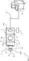
-图2显示了根据本发明的一个方面的、用于测量粘弹性介质的粘弹性的装置的示例;- Figure 2 shows an example of a device for measuring the viscoelasticity of a viscoelastic medium according to an aspect of the present invention;
-图3显示了根据图2的装置的实施方式;- Figure 3 shows an embodiment of the device according to Figure 2;
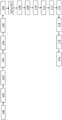
-图4显示了根据本发明的一个方面的用于测量粘弹性介质的粘弹性的方法的步骤。- figure 4 shows the steps of a method for measuring the viscoelasticity of a viscoelastic medium according to an aspect of the invention.
具体实施方式Detailed ways
本发明的第一方面提供一种用于测量粘弹性介质的粘弹性的装置DEV,所述介质在超声波照射后具有超声波信号。具体而言,本发明的装置DEV可以以即时且非侵入的方式量化肝脏纤维化。A first aspect of the invention provides a device DEV for measuring the viscoelasticity of a viscoelastic medium which has an ultrasound signal after ultrasound irradiation. Specifically, the device DEV of the present invention can quantify liver fibrosis in an immediate and non-invasive manner.
根据被选择为阐释本发明的一个方面并如图2所示的示例,装置DEV包括超声波探针1。图2显示了探针1的截面图。According to the example chosen to illustrate one aspect of the invention and shown in FIG. 2 , the device DEV comprises an
超声波探针1包括:
·包含至少一个振动器或电动致动器VIB的探针外壳PC;在一个特定实施方式中,振动器VIB包括固定部分FIX和可移动部分MOV;Probe housing PC containing at least one vibrator or electric actuator VIB; in a particular embodiment, the vibrator VIB comprises a fixed part FIX and a movable part MOV;
·第一垂直杆F1、第二垂直杆F2和水平杆F,被构造为将振动器VIB的固定部分FIX固定至探针外壳PC;· a first vertical rod F1 , a second vertical rod F2 and a horizontal rod F configured to fix the fixing part FIX of the vibrator VIB to the probe housing PC;
·具有对称轴A的超声波换能器US;Ultrasonic transducer US with axis of symmetry A;
·位置传感器POS,包括加速度计ACC,且被构造为测量作为关于时间的函数的所述探针外壳PC的位置或位移,所述位置传感器与对所述位置传感器POS提供的数据进行分析并控制所述振动器VIB的控制回路协同操作;所述位置传感器用于根据加速度、速度、或优选为位移或位置的函数控制所述探针的振动;A position sensor POS comprising an accelerometer ACC and configured to measure the position or displacement of the probe housing PC as a function of time, said position sensor analyzing and controlling the data provided by said position sensor POS The control loops of the vibrator VIB co-operate; the position sensor is used to control the vibration of the probe as a function of acceleration, velocity, or preferably displacement or position;
·探针尖端PT,具有固定至所述探针外壳PC的前端的第一端部PTE1以及固定至所述超声波换能器US的第二端部的PTE2,探针外壳PC的前端是被放置于所述组织附近的探针外壳的端部;Probe tip PT having a first end PTE1 fixed to the front end of the probe housing PC and a second end PTE2 fixed to the ultrasonic transducer US on which the front end of the probe housing PC is placed the end of the probe housing adjacent to the tissue;
·力传感器FS,设置在探针尖端和探针的剩余部分之间,并且设置在探针尖端PT上且在超声波换能器US附近,力传感器FS利用图1未显示的连接装置连接至信号生成器9;力传感器FS被构造并设置为测量探针1在待测量粘弹性组织上所施加的接触力;A force sensor FS, arranged between the probe tip and the rest of the probe, and on the probe tip PT in the vicinity of the ultrasonic transducer US, the force sensor FS is connected to the signal by means of connection means not shown in FIG. 1
·用于将所述位置传感器POS连接至控制回路和振动器VIB的连接装置,用于将超声波换能器US和力传感器FS连接至装置DEV的其他组件的连接装置;Connection means for connecting said position sensor POS to the control circuit and vibrator VIB, connection means for connecting the ultrasonic transducer US and the force sensor FS to other components of the device DEV;
·被构造并设置为显示超声波图像的显示单元7,a
·被构造并设置为启动超声波探针1的按钮8,a
·被构造并设置为发出接触就绪信号、或测量就绪信号、或发出接触就绪信号和测量就绪信号两者的信号生成器9。• A
所述装置DEV进一步包括:Said device DEV further comprises:
-被构造并设置为由操作者控制装置DEV的装置控制器10,- a
-被构造并设置为将超声波探针1链接至装置控制器10的电缆11。- a
在以下描述中,我们以肝脏作为测量其粘弹性的粘弹性介质的示例。In the following description, we use the liver as an example of a viscoelastic medium whose viscoelastic properties are measured.
具体而言,本发明的装置DEV的信号生成器9被构造并设置为当超声波探针1的换能器US接触待测量的粘弹性介质时,发射接触就绪信号。生成接触就绪信号使得可以在与装置的操作者无关的情况下获得肝脏的准确且可重现的粘弹性测量结果。In particular, the
根据本发明的一个方面,利用力传感器FS来确定接触就绪信号。实际上,当超声波探针1对病人的皮肤施加的力大于最小接触力阈值时,信号生成器9生成接触就绪信号。具体而言,力传感器FS适用于测量探针1对病人的皮肤施加的力。According to one aspect of the invention, a force sensor FS is used to determine the contact ready signal. In practice, the
根据一个实施方式,当力传感器FS测量的力大于最小接触力阈值时,信号生成器9发出接触就绪信号。According to one embodiment, the
根据一个实施方式,最小接触力阈值在0.1N至1N之间。According to one embodiment, the minimum contact force threshold is between 0.1N and 1N.
根据一个实施方式,用于接触力的最小阈值为0.5N。该最小的力级别是用于检测探针的尖端与待测量的粘弹性组织之间的接触。According to one embodiment, the minimum threshold for contact force is 0.5N. This minimum force level is used to detect contact between the tip of the probe and the viscoelastic tissue to be measured.
优选地,利用最小接触力阈值使得可以控制探针和粘弹性介质之间的接触,例如为了避免在未使用探针时发射超声波。Preferably, using a minimum contact force threshold makes it possible to control the contact between the probe and the viscoelastic medium, eg in order to avoid emitting ultrasound waves when the probe is not in use.
根据一个实施方式,当力传感器FS测量的力小于最大接触力阈值时,信号生成器9发出接触就绪信号。According to one embodiment, the
优选地,接触就绪信号使得可以防止操作者对病人身体施加过大的力进而伤害病人。Preferably, the contact ready signal prevents the operator from exerting excessive force on the patient's body and thereby injuring the patient.
优选地,接触就绪信号使得可以防止探针1因对病人身体施加很高的力而损坏。Preferably, the contact-ready signal makes it possible to prevent the
根据一个实施方式,当力传感器FS测量的力大于最小测量力阈值时,信号生成器9发出测量就绪信号。According to one embodiment, the
优选地,最小测量力阈值是必要的,以便有效地将剪切波传送到所述粘弹性介质中,并获得所述组织的粘弹性的可靠测量值。Preferably, a minimum measurement force threshold is necessary in order to effectively transmit shear waves into the viscoelastic medium and obtain reliable measurements of the viscoelasticity of the tissue.
根据本发明的一个实施方式,当所述力传感器FS测量的力在最小测量力阈值和最大测量力阈值之间时,信号生成器9发出测量就绪信号。According to an embodiment of the present invention, when the force measured by the force sensor FS is between the minimum measurement force threshold and the maximum measurement force threshold, the
根据一个实施方式,所述最小测量力阈值在1.0N至6.0N之间,所述最大测量力阈值在6.0N至20.0N之间。According to one embodiment, the minimum measurement force threshold is between 1.0N and 6.0N, and the maximum measurement force threshold is between 6.0N and 20.0N.
优选地,该力阈值的范围使得测量条件可以与超声波换能器的大小以及病人的体型相适应。例如,对于肥胖的病人,可以选择较大的超声波探针和较高的力阈值,以便准确地施加用于弹性成像测量的低频脉冲。Preferably, the range of the force threshold is such that the measurement conditions can be adapted to the size of the ultrasound transducer and the size of the patient. For example, in obese patients, larger ultrasound probes and higher force thresholds can be selected to accurately apply low-frequency pulses for elastography measurements.
根据一个实施方式,最小测量力阈值等于4N,最大测量力阈值等于8N。According to one embodiment, the minimum measurement force threshold is equal to 4N and the maximum measurement force threshold is equal to 8N.
仅当信号生成器9发出测量就绪信号时,触发粘弹性测量。优选地,当满足与测量力阈值相关的条件且发出测量就绪信号时,低频脉冲被有效地施加至粘弹性组织,且低频脉冲的形状被精确控制。The viscoelasticity measurement is only triggered when the
装置DEV包括用于仅当设定测量就绪信号时触发粘弹性介质的粘弹性的测量装置;这些装置包括接收接触就绪信号和测量就绪信号的电子微芯片或电子微处理器;如果要求获取信号,则当所述测量就绪信号被设定时,微芯片或微处理器触发粘弹性的测量。用于触发测量的装置可内置于装置控制器10中。The device DEV comprises measuring means for triggering the viscoelasticity of the viscoelastic medium only when the signal ready for measurement is set; these means comprise an electronic microchip or electronic microprocessor receiving the signal ready for contact and the signal ready for measurement; if required to acquire the signal, The microchip or microprocessor then triggers the measurement of viscoelasticity when said measurement ready signal is asserted. The means for triggering the measurements may be built into the
优选地,当满足与测量力阈值相关的条件并发出测量就绪信号时,假设皮下组织和肝脏之间的阻抗匹配,则剪切波被有效地引入病人身体中。Preferably, a shear wave is effectively introduced into the patient's body, assuming an impedance match between the subcutaneous tissue and the liver, when conditions related to the measurement force threshold are met and a measurement ready signal is issued.
根据本发明的一个实施方式,力传感器FS为电容型传感器或施加力传感器。According to one embodiment of the invention, the force sensor FS is a capacitive sensor or an applied force sensor.
该实施方式的一个优点在于精确地测量探针1对病人身体施加的力。One advantage of this embodiment is the accurate measurement of the force exerted by the
根据本发明的一个实施方式,探针1包括位置传感器POS,且装置DEV包括被构造为基于从所述位置传感器(POS)接收的信号控制振动器(VIB)的控制回路。According to one embodiment of the invention, the
控制回路可内置于探针1或装置控制器10中。在实践上,控制回路设置振动器VIB的运动参数,以获得目标低频脉冲。位置传感器POS所测量的探针1的位置被用作用于控制回路的反馈信号。The control loop can be built into the
该实施方式的一个优点在于精确地控制施加至病人身体的低频脉冲的形状。此外,探针1没有外部移动部件,因而不需要频繁的机械校准。One advantage of this embodiment is the precise control over the shape of the low frequency pulses applied to the patient's body. Furthermore, the
图3为探针1的截面图的具体呈现,探针1进一步包括从第一杆F1延伸至移动部MOV的第一弹簧K1和从第二杆F2延伸至移动部MOV的第二弹簧K2;Fig. 3 is a specific presentation of the cross-sectional view of the
根据一个实施方式,探针外壳PC呈圆柱状,轴A为所述圆柱的轴。可替代的是,探针外壳呈具有轴A的回旋体状。According to one embodiment, the probe housing PC has the shape of a cylinder, the axis A being the axis of said cylinder. Alternatively, the probe housing is in the shape of a gyroscopic body with an axis A.
探针外壳的尺寸被选择以获得手持式探针。根据该实施方式,所述圆柱的周长在120mm至160mm之间。The dimensions of the probe housing are selected to obtain a hand-held probe. According to this embodiment, the circumference of said cylinder is between 120 mm and 160 mm.
轴A为超声波换能器US的对称轴。例如,在圆柱形超声波换能器的情况中,轴A为形成换能器的圆柱体的轴。轴A还标识超声波换能器US所发射的超声波短脉冲的传播方向。Axis A is the axis of symmetry of the ultrasonic transducer US. For example, in the case of a cylindrical ultrasound transducer, axis A is the axis of the cylinder forming the transducer. Axis A also identifies the direction of propagation of the short pulses of ultrasound emitted by the ultrasound transducer US.
根据另一个实施方式,所述探针外壳PC可以具有适于在测量期间被操作者的手握持的任意形状。例如,所述探针外壳PC可具有图1b所示的标准弹性成像探针形状。According to another embodiment, said probe housing PC may have any shape suitable for being held by the operator's hand during measurements. For example, the probe housing PC may have a standard elastography probe shape as shown in Figure 1b.
振动器VIB位于探针外壳PC内部,并由两个元件形成:移动体MOV和固定元件FIX。所述振动器VIB设置为使所述移动体MOV运动,从而导致整个探针1沿轴A运动。The vibrator VIB is located inside the probe housing PC and is formed by two elements: the moving body MOV and the fixed element FIX. The vibrator VIB is arranged to move the mobile body MOV, thereby causing the
我们将垂直于轴A的方向定义为垂直方向,将平行于轴A的方向定义为水平方向。We define the direction perpendicular to the axis A as the vertical direction, and the direction parallel to the axis A as the horizontal direction.
根据一个实施方式,固定部FIX被由第一垂直杆F1、水平支撑杆F以及第二垂直杆F2形成的保持装置保持于适当位置。第一和第二垂直杆F1和F2固定至所述探针外壳。水平支撑杆F从第一垂直杆F1延伸至第二垂直杆F2。According to one embodiment, the fixing portion FIX is held in position by holding means formed by a first vertical bar F1 , a horizontal support bar F and a second vertical bar F2 . First and second vertical rods F1 and F2 are fixed to the probe housing. A horizontal support rod F extends from a first vertical rod F1 to a second vertical rod F2.
可替代的是,可以只存在一个垂直杆F1或F2,用于支撑所述水平杆F和所述振动器VIB。Alternatively, there may be only one vertical bar F1 or F2 supporting said horizontal bar F and said vibrator VIB.
保持装置F1、F和F2阻挡固定部FIX,固定部FIX随后被固定至所述探针外壳PC。也可以使用适于将振动器VIB的固定部FIX固定至探针外壳PC的保持装置的任意其他结构。The holding means F1 , F and F2 block the fixing part FIX which is then fixed to said probe housing PC. Any other structure suitable for fixing the fixing portion FIX of the vibrator VIB to the holding means of the probe housing PC may also be used.
移动部MOV分别通过两个弹簧K1和K2分别与第一和第二垂直杆F1和F2分离开。第一弹簧K1从第一垂直杆F1延伸至移动部MOV,第二弹簧从第二垂直杆F2延伸至移动部MOV。The moving part MOV is separated from the first and second vertical rods F1 and F2 by two springs K1 and K2 respectively. The first spring K1 extends from the first vertical rod F1 to the moving part MOV, and the second spring extends from the second vertical rod F2 to the moving part MOV.
当被振动器VIB致动时,移动部MOV沿水平杆F滑动。水平杆F支撑振动器VIB的固定部FIX和移动部MOV两者。The mobile part MOV slides along the horizontal rod F when actuated by the vibrator VIB. The horizontal rod F supports both the fixed part FIX and the moving part MOV of the vibrator VIB.
两个弹簧K1和K2支撑移动部MOV,并在所述移动部MOV被设置为运动时起回弹力的作用。The two springs K1 and K2 support the moving part MOV and act as resilient forces when said moving part MOV is set in motion.
值得注意的是,移动部MOV在探针外壳PC内部振荡。振动器VIB不移动惯性探针1的任何外部部件。It is worth noting that the moving part MOV oscillates inside the probe housing PC. The vibrator VIB does not move any external parts of the
根据图2所示的实施方式,移动体MOV是永磁体,固定部FIX为线圈。当对线圈FIX施加电势时,在线圈FIX和磁体MOV之间施加力,并产生移动体MOV沿轴A的振荡。According to the embodiment shown in FIG. 2, the movable body MOV is a permanent magnet, and the fixed part FIX is a coil. When an electric potential is applied to the coil FIX, a force is exerted between the coil FIX and the magnet MOV and an oscillation of the moving body MOV along the axis A is generated.
由于线圈和磁体之间的电磁力以及弹簧K1和K2施加的回弹力两者的作用,因此移动体MOV的运动引起探针外壳PC的运动。该运动可被描述为动量守恒定律的结果,移动体MOV的运动决定了探针外壳PC的反冲力。Movement of the moving body MOV causes movement of the probe housing PC due to both the electromagnetic force between the coil and the magnet and the resilient force exerted by the springs K1 and K2. This motion can be described as a consequence of the law of conservation of momentum, the motion of the mobile body MOV determining the recoil force of the probe housing PC.
因此,整个惯性探针1设置为运动,且超声波换能器US推压病人身体。Thus, the entire
该结构的优点为,超声波换能器US相对于待分析组织的运动直接由振动器VIB确定,且能被准确地控制。换言之,假设超声波换能器US相对于探针外壳PC不存在相对运动,则超声波换能器US的位移幅度与探针外壳PC的运动幅度一致。因此可以准确地控制施加至组织的低频脉冲的形状。The advantage of this configuration is that the movement of the ultrasound transducer US relative to the tissue to be analyzed is determined directly by the vibrator VIB and can be precisely controlled. In other words, assuming that there is no relative movement of the ultrasonic transducer US relative to the probe casing PC, the displacement amplitude of the ultrasonic transducer US is consistent with the movement amplitude of the probe casing PC. The shape of the low frequency pulses applied to the tissue can thus be precisely controlled.
根据本发明,存在将超声波换能器US固定至探针外壳PC的多种可用方案。According to the invention, there are various possible solutions for fixing the ultrasound transducer US to the probe housing PC.
根据一个实施方式,超声波换能器US可以直接固定至探针外壳PC。可替代的是,超声波换能器US可以固定至力传感器FS,力传感器FS再附装至探针外壳PC。According to one embodiment, the ultrasound transducer US can be fixed directly to the probe housing PC. Alternatively, the ultrasonic transducer US may be fixed to the force sensor FS, which in turn is attached to the probe housing PC.
该实施方式的优点在于,该结构易于实现。此外,力传感器FS直接与超声波换能器US接触,从而使检测探针外壳的形变更有效。探针外壳PC的形变是微观形变(micrometricdeformation),并由超声波换能器US和待分析组织之间的接触引起。The advantage of this embodiment is that the structure is easy to realize. Furthermore, the force sensor FS is in direct contact with the ultrasonic transducer US, making detection of deformation of the probe housing more efficient. The deformation of the probe housing PC is a micrometric deformation and is caused by the contact between the ultrasound transducer US and the tissue to be analyzed.
根据图2所示的实施方式,超声波换能器US固定至探针尖端PT,探针尖端PT包括第一端部PTE1。第一端部PTE1固定至探针外壳PC的前端。例如,探针尖端PT呈明显的圆柱形,如图1所示。According to the embodiment shown in Fig. 2, the ultrasound transducer US is fixed to the probe tip PT comprising a first end PTE1. The first end portion PTE1 is fixed to the front end of the probe housing PC. For example, the probe tip PT has a distinct cylindrical shape, as shown in FIG. 1 .
例如,如图2所示,通过将探针尖端的第一端部PTE1插入力传感器FS中的外壳HOU中,探针尖端PT可锁定至探针外壳PC。探针尖端的第二端部PTE2固定至超声波换能器US。For example, as shown in FIG. 2 , the probe tip PT can be locked to the probe housing PC by inserting the first end PTE1 of the probe tip into the housing HOU in the force sensor FS. The second end PTE2 of the probe tip is fixed to the ultrasound transducer US.
该实施方式的优点在于,探针尖端PT易于更换。换言之,可以使用具有不同超声波换能器US的不同的探针尖端PT,以便使所发射的超声波束的特性与组织或病人身体的特性相适应。An advantage of this embodiment is that the probe tip PT is easy to replace. In other words, different probe tips PT with different ultrasound transducers US can be used in order to adapt the properties of the emitted ultrasound beam to the properties of the tissue or the patient's body.
根据一个实施方式,利用位置传感器POS测量惯性探针1的运动。According to one embodiment, the motion of the
该实施方式的优点在于直接测量探针外壳PC的运动幅度,该运动幅度与超声波换能器US的运动幅度相同。实际上,根据本发明,超声波换能器US相对于探针外壳PC不存在运动是可能的。也就是说,超声波换能器US在探针外壳PC的参照系中静止不动。The advantage of this embodiment is that the amplitude of movement of the probe housing PC is directly measured, which is the same as that of the ultrasonic transducer US. Indeed, according to the invention, no movement of the ultrasound transducer US relative to the probe housing PC is possible. That is to say, the ultrasound transducer US is stationary in the frame of reference of the probe housing PC.
在图3所示的实施方式中,位置传感器POS由加速度计ACC和执行双重时间积分(double temporal integration)的电路DI形成。双重积分器DI根据测量的加速度给出探针的位置r。In the embodiment shown in FIG. 3 , the position sensor POS is formed by an accelerometer ACC and a circuit DI performing a double temporal integration. The double integrator DI gives the position r of the probe from the measured acceleration.
本发明也可以使用能根据测量的加速度计算位置r的任意电路。The present invention can also use any circuit that can calculate the position r from the measured acceleration.
优选的是,位置传感器POS提供对超声波换能器US的位移的直接测量。也就是说,位置传感器POS直接测量施加至组织的低频脉冲的形状,以便在组织内产生瞬时剪切波。Preferably, the position sensor POS provides a direct measurement of the displacement of the ultrasound transducer US. That is, the position sensor POS directly measures the shape of the low frequency pulse applied to the tissue in order to generate a transient shear wave within the tissue.
探针1然后用于与能驱动振动器VIB的控制回路协作,以便获得预定义的低频脉冲形状。举例来说,控制回路可以内置在
然后,位置传感器POS所测量的位置r被用作用于控制振动器VIB的反馈信号。根据一个实施方式,位置r被馈送给控制移动体MOV的振荡的幅度和频率的控制回路。The position r measured by the position sensor POS is then used as a feedback signal for controlling the vibrator VIB. According to one embodiment, the position r is fed to a control loop controlling the amplitude and frequency of the oscillations of the mobile body MOV.
得益于这种设置,可以直接控制超声波换能器US的运动,并向病人身体施加良好定义的低频脉冲。Thanks to this setup, it is possible to directly control the movement of the ultrasound transducer US and apply well-defined low-frequency pulses to the patient's body.
根据图3所示的实施方式,探针1还包括用于在位置传感器POS、控制回路和振动器VIB之间传输电信号的连接装置。所述连接装置还包括用于传递所需的电力的装置,以操作振动器VIB、超声波换能器US和其他内置设备。所述电力传递装置在图3中未显示。According to the embodiment shown in FIG. 3 , the
根据图3所示的实施方式,力传感器FS为装备有至少一个应变仪SG或其他应力传感器的尖端保持器TH。图3的力传感器还适于接收并锁定探针尖端PT的端部。According to the embodiment shown in FIG. 3 , the force sensor FS is a tip holder TH equipped with at least one strain gauge SG or other stress sensor. The force sensor of Fig. 3 is also adapted to receive and lock the end of the probe tip PT.
根据一个实施方式,连接位置传感器POS、控制回路和振动器VIB的装置可以是无线的。According to one embodiment, the means connecting the position sensor POS, the control loop and the vibrator VIB may be wireless.
本发明的一个优点是可以定义和精细控制施加至组织的低频脉冲。位置传感器POS测量超声波换能器US的实际运动。控制回路调节移动体MOV的振荡特性,以向病人的身体施加目标低频脉冲形状。One advantage of the present invention is that the low frequency pulses applied to tissue can be defined and finely controlled. The position sensor POS measures the actual movement of the ultrasonic transducer US. A control loop adjusts the oscillation characteristics of the moving body MOV to impart a target low frequency pulse shape to the patient's body.
在典型的瞬时弹性成像应用时,施加至病人身体的低频脉冲呈正弦曲线形,其中心频率在1Hz至5000Hz之间,峰-峰振幅在10μm至20mm之间,且持续周期在100μs至20s之间。超声波脉冲的重复率在100Hz至100000Hz之间。In a typical transient elastography application, the low-frequency pulse applied to the patient's body is sinusoidal, with a center frequency between 1Hz and 5000Hz, a peak-to-peak amplitude between 10μm and 20mm, and a duration between 100μs and 20s between. The repetition rate of the ultrasonic pulses is between 100 Hz and 100,000 Hz.
根据一个实施方式,峰-峰振幅在50μm至5mm之间。According to one embodiment, the peak-to-peak amplitude is between 50 μm and 5 mm.
通过使换能器推压组织,探针外壳PC的运动被传输至组织。由于探针1也是与操作者的手动态连接的事实,因此难以确定US换能器相对于组织的实际运动。操作者的手的运动不可避免地改变了施加至病人身体的低频脉冲的形状。Movement of the probe housing PC is transmitted to the tissue by causing the transducer to push against the tissue. Due to the fact that the
本发明通过消除超声波换能器US相对于探针外壳PC的运动,并利用位置传感器POS测量探针外壳PC自身的位置,解决了该问题。测量的位置被用作振动器VIB的参数的反馈。然后调节振动器VIB的参数,直至获得预定义的低频脉冲形状。The present invention solves this problem by eliminating the movement of the ultrasonic transducer US relative to the probe housing PC and measuring the position of the probe housing PC itself with the position sensor POS. The measured position is used as feedback for the parameters of the vibrator VIB. Then adjust the parameters of the vibrator VIB until a predefined low-frequency pulse shape is obtained.
也就是说,探针1没有外部机械可移动部件。于是,探针1是惯性探针,其运动由位于探针外壳内的物体MOV的运动决定。由于不存在超声波换能器US相对于探针外壳PC的相对运动,因此测量探针外壳PC的位移幅度等效于测量超声波换能器US的位移。于是,探针1接着能直接测量施加至组织的低频脉冲的形状,并补偿操作者的手的可能存在的运动。没有外部可移动部件也免除了探针的频繁机械校准的必要。That is, the
根据本发明的另一个实施方式,移动部MOV的质量等于或大于惯性探针1的总质量M的四分之一。According to another embodiment of the present invention, the mass of the moving part MOV is equal to or greater than a quarter of the total mass M of the
该实施方式的一个优点是,可通过简单地改变移动部MOV的运动,就使得可以有效地控制惯性探针1的整体运动。也就是说,如果移动部MOV的质量较小,则它对整个惯性探针1的运动的影响就因动量守恒定律而较小。于是,对尖端的运动的控制就不太有效了。An advantage of this embodiment is that it allows efficient control of the overall motion of the
根据一个实施方式,US换能器是盘状超声波换能器。According to one embodiment, the US transducer is a disk-shaped ultrasound transducer.
该形状的一个优点是可以以极高的对称性发射超声波束。高对称性的情况简化了超声波束和剪切波的传播的计算。An advantage of this shape is that the ultrasound beam can be emitted with great symmetry. The case of high symmetry simplifies the calculation of the propagation of ultrasound beams and shear waves.
根据本发明的一个方面,力传感器FS包括处理器,所述处理器适于计算并向信号生成器9发送所施加的力。According to an aspect of the invention, the force sensor FS comprises a processor adapted to calculate and send the applied force to the
根据本发明的一个方面,当接触就绪信号被设定时,超声波探针1被构造并设置为点亮所述超声波探针1的至少一个发光二极管(LED)。实际上,点亮LED是用于向操作者通知超声波探针1已经与病人的皮肤正确地接触,从而操作者停止增大对所述病人的皮肤施加的力。According to an aspect of the invention, the
根据本发明的另一个方面,信号生成器9上的声学指示器被构造并设置为向用户指示接触就绪信号已被设定。According to another aspect of the invention, the acoustic indicator on the
除此以外,根据本发明的一个方面,当接触就绪信号被设定时,换能器US被构造并设置为发射超声波信号。Besides, according to an aspect of the present invention, the transducer US is constructed and arranged to emit an ultrasonic signal when the contact ready signal is set.
装置控制器10被构造并设置为控制换能器US所产生的超声波信号的频率。The
根据一个实施方式,装置控制器10还被构造并设置为通过控制回路并使用位置传感器POS所测量的位置用作反馈来控制振动器VIB的运动参数。According to one embodiment, the
由超声波探针1的超声波换能器US实现的超声波信号发射和接收使得能获得待分析介质的一部分的连续图像。因此,仅当换能器US接触待测量的粘弹性介质时,执行所述图像的产生。此外,超声波换能器US所获得的图像是一维的。根据未显示的本发明的一个方面,装置DEV包括可以任意方式放置的多个超声波换能器US,例如以线性(类似于超声棒(echographic rod))或蜂窝图案的方式。根据这种方式,装置DEV可以获得三维图像。因此,可以在待分析介质的不同区域中测量粘弹性。The transmission and reception of ultrasound signals by the ultrasound transducer US of the
此外,根据本发明的一个方面,当接触就绪信号被设定时,也被称为“字母数字显示屏”的显示单元7被构造并设置为刷新超声波图像。实际上,超声波探针1的字母数字显示屏7被构造并设置为显示超声波图像。显示所述图像可以帮助操作者定位他想要进行粘弹性测量的区域。Furthermore, according to an aspect of the invention, the
此外,根据本发明的一个方面,当接触就绪信号被设定时,引导指示符被刷新。“引导指示符”表示显示给操作者的指示符,用于帮助他定位最佳测量位置。Additionally, according to an aspect of the invention, the boot indicator is refreshed when the contact ready signal is asserted. "Guide indicator" means an indicator displayed to the operator to help him locate the best measurement position.
此外,根据本发明的一个方面,当接触就绪信号被设定时,装置控制器10被构造并设置为限制访问装置控制器10的至少一个命令。Furthermore, according to an aspect of the present invention, the
除此以外,本发明的装置DEV的信号生成器9被构造并设置为发射测量就绪信号。实际上,施加在身体上的过高的力会对粘弹性测量结果造成偏差。In addition, the
根据本发明的一个方面,利用力传感器FS确定测量就绪信号。实际上,当超声波探针1对病人皮肤施加的力大于最小测量力阈值且小于最大测量力阈值时,信号生成器9产生测量就绪信号。According to one aspect of the invention, the ready-to-measure signal is determined with the force sensor FS. Actually, when the force exerted by the
根据本发明的一个方面,力传感器FS包括适于计算并向信号生成器9发送所测量的接触力的值。According to an aspect of the invention, the force sensor FS comprises a value suitable for calculating and sending to the
根据本发明的一个方面,当测量就绪信号被设定时,超声波探针1点亮至少一个发光二极管(LED)。实际上,点亮LED是用于向用户通知他能产生低频脉冲了。According to an aspect of the invention, the
根据本发明的另一个方面,信号生成器9上的声学指示器被构造并设置为向操作者指示以声音类型区分的接触就绪信号和/或测量就绪信号。According to another aspect of the invention, the acoustic indicator on the
根据本发明的一个方面,仅当信号生成器9发出测量就绪信号时,振动器VIB才进行运动,以施加低频脉冲。根据一个实施方式,装置控制器10基于位置传感器POS所提供的反馈信号,控制振动器VIB。According to one aspect of the invention, the vibrator VIB is moved to apply low frequency pulses only when the
具体而言,根据本发明的一个方面,装置控制器10被构造并设置为通过控制电动致动器VIB来控制振动器VIB在病人皮肤上产生的机械剪切波的功率。此外,装置控制器10被构造并设置为监控在介质中所产生的剪切波的数量。Specifically, according to one aspect of the present invention, the
除此以外,根据本发明的一个方面,受装置控制器10控制的电动致动器VIB构造并设置为产生瞬时低频脉冲,其频率范围在约1Hz至约5000Hz之间。术语“瞬时低频脉冲”意指预定持续周期的机械应力,其频率在约1Hz至约5000Hz之间,峰-峰振幅在约10μm(微米)至20毫米之间,优选在约500μm至约5mm之间。所述应力的持续周期在约100μs至约20秒之间,优选在约5ms至约40ms(毫秒)之间。Additionally, according to one aspect of the present invention, the electric actuator VIB controlled by the
因此,受于装置控制器控制的电动致动器VIB可以提供能产生在时间和振幅上被完美控制的低频振动或应力的装置DEV。脉冲的波形被较好地控制,从而能获得更可靠的测量值,进而提高了系统的可重现性。此外,利用受控的电动致动器VIB,装置DEV的体积和重量减小。Thus, an electric actuator VIB under the control of a device controller can provide a device DEV capable of generating low frequency vibrations or stresses that are perfectly controlled in time and amplitude. The shape of the pulses is better controlled, resulting in more reliable measurements and thus increased system reproducibility. Furthermore, with the controlled electric actuator VIB, the volume and weight of the device DEV are reduced.
此外,具体而言,超声波换能器US构造并设置为发射和接收受装置控制器10控制的超声波信号。具体而言,装置控制器10被构造并设置为控制发射超声波信号的范围和频率。在向病人皮肤产生低频脉冲的同时,换能器US发射和接收超声波信号以追踪产生的剪切波的传播。追踪剪切波可允许通过确定介质的粘弹性来执行测量。实际上,剪切波具有特殊性质:其速度取决于其已经穿过的介质的粘弹性。肝脏越硬(因此纤维化程度越高),剪切波传播越快。Furthermore, specifically, the ultrasound transducer US is constructed and arranged to transmit and receive ultrasound signals controlled by the
此外,当装置DEV包括多于一个的换能器时,装置控制器10可以控制换能器的频率。Furthermore, when the device DEV includes more than one transducer, the
此外,根据本发明的一个方面,超声波换能器US呈纵长状,例如椭圆形、矩形、圆柱形或椭球形,其长度在约2至约20毫米之间,优选约11毫米,且其宽度在约1至约10毫米之间,优选约5毫米。In addition, according to one aspect of the present invention, the ultrasonic transducer US is elongated, such as oval, rectangular, cylindrical or ellipsoid, and its length is between about 2 and about 20 mm, preferably about 11 mm, and its The width is between about 1 and about 10 mm, preferably about 5 mm.
根据本发明的一个方面,超声波换能器US可优选为呈圆锥形或锥形,角度在约10至约80度之间。According to one aspect of the present invention, the ultrasonic transducer US may preferably be conical or tapered, with an angle between about 10 and about 80 degrees.
此外,根据本发明的一个实施方式,装置控制器10包括触摸屏、键盘以及可选的鼠标。此外,通过利用柔性电缆11链接至超声波探针1的装置控制器10允许操作者通过显示屏(也称为“操作者界面”)读取超声波探针1所提供的信息。Furthermore, according to one embodiment of the present invention, the
在本发明的另一个实施方式中,装置控制器10可以删除测量值、和/或改变检测类型(弹性成像或B超)、和/或增加评论或测量值、和/或改变超声波增益和/或……。In another embodiment of the invention, the
本发明还涉及一种利用上文所述的装置DEV测量粘弹性介质的粘弹性的方法MET,所述介质在超声波照射后具有超声波信号。The invention also relates to a method MET for measuring the viscoelasticity of a viscoelastic medium, which has an ultrasonic signal after ultrasonic irradiation, using the device DEV described above.
图4显示了用于测量粘弹性介质的粘弹性的方法MET的步骤的示例。Figure 4 shows an example of the steps of the method MET for measuring the viscoelasticity of viscoelastic media.
如图4所示,方法MET包括将超声波换能器US定位100为接触待测量的粘弹性介质。As shown in Fig. 4, the method MET comprises positioning 100 the ultrasound transducer US in contact with the viscoelastic medium to be measured.
然后,方法MET包括操作者利用超声波探针1对待测量的介质施加第一力101。一般而言,对于评估肝脏纤维化而言,超声波换能器US在覆盖肋骨的部位施加力。The method MET then includes the operator applying a
根据本发明的另一个方面,方法MET包括测量102超声波探针1对待测量的介质施加的第一力,然后将第一力的测量结果与最小接触力阈值进行比较。根据本发明的一个方面,最小接触力阈值等于0.5N。According to another aspect of the invention, the method MET comprises measuring 102 a first force exerted by the
根据本发明的另一个方面,方法MET包括将所测量的接触力与最大接触力阈值进行比较的步骤103。According to another aspect of the invention, the method MET comprises a
然后,方法MET包括由信号生成器9基于所测量的接触力与预定义的力阈值的比较结果生成104接触就绪信号。我们回顾一下,当超声波探针1接触待分析介质时,接触就绪信号被设定。当接触力高于最小接触力阈值时发出接触就绪信号。根据一个实施方式,当接触力在最小和最大接触力阈值之间时发出接触就绪信号。The method MET then comprises generating 104 a contact ready signal by the
根据本发明的一个方面,方法MET包括点亮超声波探针1的至少一个发光二极管LED的步骤105,仅当接触就绪信号被设定时点亮所述LED。According to one aspect of the invention, the method MET comprises a
根据本发明的一个方面,方法MET进一步包括激活超声波信号的步骤106。因此,超声波换能器US发射和接收超声波信号以产生感兴趣区域的图像。我们注意到,仅当接触就绪信号被设定时,超声波换能器US激活超声波信号的发射和接收。According to an aspect of the invention, the method MET further comprises a
根据本发明的一个方面,方法MET包括仅当发出接触就绪信号时显示定位装置的步骤107a。定位装置是操作者用于定位待测量粘弹性组织的工具;定位装置的示例为图像、引导工具或其他指示符。According to one aspect of the invention, the method MET includes a
根据本发明的一个方面,方法MET包括刷新超声波图像的步骤107,仅当接触就绪信号被设定时,显示单元显示所述超声波图像。According to one aspect of the invention, the method MET comprises a
根据本发明的一个方面,方法MET包括随后利用引导指示符进行引导的步骤108,仅当接触就绪信号被设定时,刷新所述引导指示符。According to one aspect of the invention, the method MET comprises a
根据本发明的一个方面,方法MET包括当接触就绪信号被设定时限制访问由装置控制器10所提供的至少一个命令的步骤109。According to one aspect of the invention, the method MET comprises a
根据本发明的一个方面,方法MET包括当接触就绪信号被设定时,由超声波探针1激活写入探针存储器的步骤110。According to one aspect of the invention, the method MET comprises a
方法MET包括操作者利用超声波探针1对介质施加第二力111,第二力111大于第一力101。根据本发明的另一个方面,方法MET包括测量超声波探针1所施加的第二力。然后,将第二力的测量结果与最小测量力阈值进行比较。还可以将第二力的值与最大测量力阈值进行比较。The method MET includes the operator applying a
根据本发明的一个方面,最小测量力阈值等于4.0N。根据本发明的一个方面,最大测量力阈值等于8.0N。According to an aspect of the invention, the minimum measurement force threshold is equal to 4.0N. According to an aspect of the invention, the maximum measured force threshold is equal to 8.0N.
根据本发明的一个方面,方法MET包括如果测量的第二力大于最小测量力阈值,则利用信号生成器9生成111测量就绪信号。According to an aspect of the invention, the method MET comprises generating 111 a measurement ready signal with the
根据本发明的一个实施方式,当测量的第二力在最小和最大测量力阈值之间时,信号生成器设定111测量就绪信号进行。According to one embodiment of the invention, the signal generator sets 111 the measurement ready signal to proceed when the measured second force is between the minimum and maximum measured force thresholds.
根据本发明的一个方面,所述方法包括当测量就绪信号被设定时点亮超声波探针1的至少一个发光二极管LED的步骤112。According to an aspect of the invention, the method comprises a
根据本发明的一个方面,方法MET包括向病人的皮肤生成低频脉冲的步骤113。利用整个探针1的运动产生所述低频脉冲,所述运动由电动致动器VIB产生。所述电动致动器VIB受装置控制器10控制。仅当信号生成器9发出的测量就绪信号被设定时,才触发根据步骤113的施加低频脉冲。According to one aspect of the invention, the method MET comprises a
根据本发明的一个方面,方法MET进一步包括利用超声波换能器US发射和接收超声波信号以追踪剪切波的传播的步骤114,所述剪切波是通过向病人皮肤生成低频脉冲113而产生的。实际上,剪切波传播速度取决于传播介质的粘弹性。肝脏越硬,剪切波传播越快。通过超声波换能器US并通过对射频超声波信号使用互相关技术来测量在剪切波传播期间引起的肝脏内的位移。According to an aspect of the invention, the method MET further comprises the
除此以外,根据本发明的一个方面,方法MET包括当接触就绪信号被设定时停用装置DEV的组合治疗的步骤115。在此,“组合治疗”表示在装置内组合的另一种类型的检查。例如,组合治疗为心电图ECG或B超成像。在本发明的一个非限制性实施方式中,装置DEV具有两个探针,每一个用于一种治疗:用于弹性成像的第一超声波探针,用于B超成像的第二超声波探针,也称为成像探针。在该情况下,接触就绪信号用于激活或停用这些探针中的一个。出于安全原因,很重要的一点是,不能超出给定应用所允许的最大声学输出功率。因此,很重要的一点是,不能同时用装置DEV的两个探针发射超声波信号。此外,同时使用两个探针(用于弹性成像的超声波探针和成像探针)无疑会在两种超声波信号的采集上产生伪数据,因为来自各探针的信号会干扰。在本发明的一个非限制性实施方式中,当接触就绪信号被设定时,停用一种治疗,而激活另一种治疗。Besides that, according to one aspect of the invention, the method MET comprises a
方法MET包括如第2005/0203398号美国专利所描述的那样测量待分析介质的粘弹性的步骤116。The method MET comprises a
此外,根据本发明的一个方面,在装置DEV和病人皮肤之间放置对于超声波透明的弹性中间介质(图中未显示)。根据本发明的一个方面,所述中间介质是聚丙烯酰胺型合成聚合物。此外,在所述中间介质和待研究的介质之间可放置粘性材料或胶水,以获得滑动界面或链接界面。除此以外,所述中间介质是创新性的,因为它不仅对于超声波是透明的,而且对于低频波也是透明的。所述中间介质被选择为使其弹性与待研究介质接近,以调节阻抗,并由此能将最大的能量发送给待研究介质。所述中间介质也可以被压缩,从而使得该中间介质的以非线性方式变化的弹性模量变得与待研究介质相近。这最后的建议更是用于测量介质的弹性的原创技术:它包括改变中间介质的弹性直至发送最大能量。这样获得的弹性接近于介质的弹性。Furthermore, according to an aspect of the present invention, an elastic intermediate medium (not shown in the figure) transparent to ultrasound is placed between the device DEV and the patient's skin. According to one aspect of the invention, said intermediate medium is a synthetic polymer of polyacrylamide type. Furthermore, a viscous material or glue can be placed between the intermediate medium and the medium to be studied in order to obtain a sliding or linking interface. Besides that, the intermediate medium is innovative because it is not only transparent to ultrasound waves, but also to low frequency waves. The intermediate medium is chosen such that its elasticity is close to that of the medium under investigation, in order to adjust the impedance and thus enable the transmission of maximum energy to the medium under investigation. The intermediate medium can also be compressed such that the non-linearly varying modulus of elasticity of the intermediate medium becomes similar to that of the medium to be investigated. This last proposal is rather an original technique for measuring the elasticity of the medium: it consists in varying the elasticity of the intermediate medium until the maximum energy is transmitted. The elasticity thus obtained is close to that of the medium.
根据本发明的一个方面,在标准回波描记模式下,以通常每秒获得组织或介质的20个超声波信号的方式使用超声波探针1。这些超声波信号的包络显示在字母数字显示屏7上。将当前信号编码为灰度和对数尺度,以形成称为A模图像的图像。所述信号可被并排放置以构成称为M模图像的图像,M模图像包含给定时间段内获得的超声波信号,例如5秒。根据本发明的一个方面,超声波探针1配备有定位系统,以知晓操作者在组织或介质表面移动超声波探针1时获得信号的位置,从而重建待测量介质的图像。除此以外,根据本发明的一个方面,仅当接触就绪信号被设定时,字母数字显示屏7刷新超声波图像。根据本发明的另一个方面,仅在装置控制器10的屏幕上显示超声波图像。According to one aspect of the invention, the
Claims (17)
Translated fromChinesePriority Applications (1)
| Application Number | Priority Date | Filing Date | Title |
|---|---|---|---|
| CN202310043432.XACN116196037A (en) | 2017-03-27 | 2018-03-26 | Device and method for measuring the viscoelasticity of a visco-elastic medium |
Applications Claiming Priority (3)
| Application Number | Priority Date | Filing Date | Title |
|---|---|---|---|
| EP17163075.9AEP3381374B1 (en) | 2017-03-27 | 2017-03-27 | Device and method for measuring the viscoelastic properties of a viscoelastic medium |
| EP17163075.9 | 2017-03-27 | ||
| PCT/EP2018/057609WO2018177991A1 (en) | 2017-03-27 | 2018-03-26 | Device and method for measuring the viscoelastic properties of a viscoelastic medium |
Related Child Applications (1)
| Application Number | Title | Priority Date | Filing Date |
|---|---|---|---|
| CN202310043432.XADivisionCN116196037A (en) | 2017-03-27 | 2018-03-26 | Device and method for measuring the viscoelasticity of a visco-elastic medium |
Publications (2)
| Publication Number | Publication Date |
|---|---|
| CN110520055A CN110520055A (en) | 2019-11-29 |
| CN110520055Btrue CN110520055B (en) | 2022-12-02 |
Family
ID=58428192
Family Applications (3)
| Application Number | Title | Priority Date | Filing Date |
|---|---|---|---|
| CN201710309396.1AActiveCN108652667B (en) | 2017-03-27 | 2017-05-04 | Device and method for measuring the viscoelasticity of a visco-elastic medium |
| CN201880022597.6AActiveCN110520055B (en) | 2017-03-27 | 2018-03-26 | Device and method for measuring viscoelasticity of viscoelastic media |
| CN202310043432.XAPendingCN116196037A (en) | 2017-03-27 | 2018-03-26 | Device and method for measuring the viscoelasticity of a visco-elastic medium |
Family Applications Before (1)
| Application Number | Title | Priority Date | Filing Date |
|---|---|---|---|
| CN201710309396.1AActiveCN108652667B (en) | 2017-03-27 | 2017-05-04 | Device and method for measuring the viscoelasticity of a visco-elastic medium |
Family Applications After (1)
| Application Number | Title | Priority Date | Filing Date |
|---|---|---|---|
| CN202310043432.XAPendingCN116196037A (en) | 2017-03-27 | 2018-03-26 | Device and method for measuring the viscoelasticity of a visco-elastic medium |
Country Status (6)
| Country | Link |
|---|---|
| US (5) | US11331073B2 (en) |
| EP (1) | EP3381374B1 (en) |
| JP (1) | JP7134999B2 (en) |
| CN (3) | CN108652667B (en) |
| ES (1) | ES2833934T3 (en) |
| WO (1) | WO2018177991A1 (en) |
Cited By (1)
| Publication number | Priority date | Publication date | Assignee | Title |
|---|---|---|---|---|
| CN108652667A (en)* | 2017-03-27 | 2018-10-16 | 法国爱科森有限公司 | Viscoelastic device and method for measuring viscoelastic medium |
Families Citing this family (16)
| Publication number | Priority date | Publication date | Assignee | Title |
|---|---|---|---|---|
| CN209574737U (en)* | 2018-11-09 | 2019-11-05 | 无锡海斯凯尔医学技术有限公司 | Shell, probe and detection device |
| US12121400B2 (en)* | 2019-04-10 | 2024-10-22 | Clarius Mobile Health Corp. | Ultrasound imaging apparatus with an add-on vibration inducing device for ultrasound elastography |
| CN110477949B (en)* | 2019-08-26 | 2022-11-29 | 东软医疗系统股份有限公司 | Ultrasonic imaging method and device and ultrasonic imaging equipment |
| CN110720948B (en)* | 2019-11-12 | 2021-02-02 | 无锡海斯凯尔医学技术有限公司 | Biosign detection method based on ultrasonic detection system |
| US11213277B2 (en)* | 2019-12-09 | 2022-01-04 | National Cheng Kung University | Measuring apparatus and system for measuring elasticity of biological tissue |
| CN114144119A (en)* | 2020-05-14 | 2022-03-04 | 深圳迈瑞生物医疗电子股份有限公司 | Instantaneous elasticity measurement method, acoustic attenuation parameter measurement method and ultrasonic imaging system |
| FR3115603B1 (en)* | 2020-10-22 | 2024-08-16 | E Scopics | PROBE FOR MEASURING VISCOELASTIC PROPERTIES OF A MEDIUM |
| JP7077433B1 (en) | 2021-02-10 | 2022-05-30 | ジーイー・プレシジョン・ヘルスケア・エルエルシー | Control program for ultrasonic diagnostic equipment, ultrasonic diagnostic system and ultrasonic diagnostic equipment |
| GB2606699A (en)* | 2021-04-20 | 2022-11-23 | Jr Dynamics Ltd | Ultrasonic coupling |
| IL294313B2 (en)* | 2021-07-09 | 2025-02-01 | Echosens | Elastography device and method |
| US11872082B2 (en)* | 2021-07-09 | 2024-01-16 | Echosens | Elastography device and method |
| NL2031483B1 (en)* | 2022-04-04 | 2023-10-25 | Teledyne Dalsa Bv | System for screening tissue on the presence of malignant cells |
| US20250312016A1 (en)* | 2022-04-28 | 2025-10-09 | Koninklijke Philips N.V. | Ultrasound imaging |
| EP4268728A1 (en)* | 2022-04-28 | 2023-11-01 | Koninklijke Philips N.V. | An ultrasound device and method of controlling an ultrasound device |
| CN115067996B (en)* | 2022-06-15 | 2025-04-04 | 深圳市影越医疗科技有限公司 | A vibration detection device, probe, method and system for elasticity detection |
| CN115153638B (en)* | 2022-07-25 | 2025-07-01 | 重庆三峡医药高等专科学校 | A method for testing facial elastic modulus |
Citations (4)
| Publication number | Priority date | Publication date | Assignee | Title |
|---|---|---|---|---|
| EP1473058A1 (en)* | 2003-01-23 | 2004-11-03 | L'oreal | Apparatus for analysis of the skin comprising an ultrasonic probe |
| FR2928077A1 (en)* | 2008-02-29 | 2009-09-04 | Echosens Sa | DEVICE AND METHOD FOR MICROELASTOGRAPHY |
| EP2310829A1 (en)* | 2008-07-30 | 2011-04-20 | Centre Hospitalier De L'Universite de Montreal | A system and method for detection, characterization and imaging of heterogeneity using shear wave induced resonance |
| CN105640593A (en)* | 2014-11-18 | 2016-06-08 | 爱科森股份有限公司 | Elasticity measurement device for measuring elastic medium |
Family Cites Families (41)
| Publication number | Priority date | Publication date | Assignee | Title |
|---|---|---|---|---|
| JPS6043134B2 (en) | 1977-08-25 | 1985-09-26 | 信紘 佐藤 | Device for measuring reflection characteristics of biological organs and tissues |
| JP4079396B2 (en)* | 1998-06-25 | 2008-04-23 | 株式会社日立メディコ | Intracavity ultrasound probe |
| FR2791136B1 (en) | 1999-03-15 | 2001-06-08 | Mathias Fink | IMAGING METHOD AND DEVICE USING SHEAR WAVES |
| US8135448B2 (en)* | 2001-03-16 | 2012-03-13 | Nellcor Puritan Bennett Llc | Systems and methods to assess one or more body fluid metrics |
| JP4258015B2 (en) | 2002-07-31 | 2009-04-30 | 毅 椎名 | Ultrasonic diagnostic system, strain distribution display method, and elastic modulus distribution display method |
| US7578789B2 (en) | 2002-08-08 | 2009-08-25 | Echosens | Device and method for measuring the elasticity of a human or animal organ |
| FR2843290B1 (en) | 2002-08-08 | 2005-06-24 | Echosens | DEVICE AND METHOD FOR MEASURING THE ELASTICITY OF A HUMAN OR ANIMAL ORGAN |
| JP2005013283A (en) | 2003-06-23 | 2005-01-20 | Takeshi Shiina | Ultrasonic probe and ultrasonic diagnostic apparatus |
| CA2457376C (en) | 2003-10-14 | 2015-09-15 | The University Of British Columbia | Method for imaging the mechanical properties of tissue |
| JP4189840B2 (en) | 2003-10-20 | 2008-12-03 | 独立行政法人産業技術総合研究所 | Apparatus and program for estimating viscoelasticity of soft tissue using ultrasound |
| FR2875695B1 (en)* | 2004-09-28 | 2006-12-01 | Echosens Sa | INSTRUMENT FOR MEASURING THE ELASTICITY OF AN ORGAN OF THE TYPE COMPRISING A MEANS OF CENTERING |
| US9043156B2 (en)* | 2008-10-28 | 2015-05-26 | The University Of North Carolina At Chapel Hill | Methods, systems, and computer readable media for monitored application of mechanical force to samples using acoustic energy and mechanical parameter value extraction using mechanical response models |
| FR2939512B1 (en)* | 2008-12-04 | 2012-07-27 | Echosens | DEVICE AND METHOD FOR ELASTOGRAPHY |
| WO2011004661A1 (en) | 2009-07-07 | 2011-01-13 | 株式会社 日立メディコ | Ultrasonic diagnosis apparatus and ultrasonic measurement method |
| US8500639B2 (en)* | 2009-09-11 | 2013-08-06 | Mr Holdings (Hk) Limited | Systems and methods for shear wave field formation |
| CN101699280B (en)* | 2009-10-15 | 2011-08-17 | 北京索瑞特医学技术有限公司 | Method and device for ultrasonic and nondestructive detection of elasticity of viscoelastic medium |
| US9456800B2 (en)* | 2009-12-18 | 2016-10-04 | Massachusetts Institute Of Technology | Ultrasound scanning system |
| US8333704B2 (en) | 2009-12-18 | 2012-12-18 | Massachusetts Institute Of Technology | Handheld force-controlled ultrasound probe |
| US9538982B2 (en)* | 2010-12-18 | 2017-01-10 | Massachusetts Institute Of Technology | User interface for ultrasound scanning system |
| WO2012094308A1 (en)* | 2011-01-03 | 2012-07-12 | Massachusetts Institute Of Technology | Quantitative elastography |
| CA2823729C (en)* | 2011-02-15 | 2022-06-14 | Hemosonics, Llc | Devices, systems and methods for evaluation of hemostasis |
| CN102151152A (en)* | 2011-03-01 | 2011-08-17 | 深圳市一体医疗科技股份有限公司 | Measurement probe, system and method for measuring elasticity of viscoelastic medium |
| US20120316407A1 (en) | 2011-06-12 | 2012-12-13 | Anthony Brian W | Sonographer fatigue monitoring |
| US10667791B2 (en) | 2011-08-19 | 2020-06-02 | The University Of British Columbia | Elastography using ultrasound imaging of a thin volume |
| US9584925B2 (en) | 2011-12-07 | 2017-02-28 | Cochlear Limited | Electromechanical transducer with mechanical advantage |
| KR102070262B1 (en) | 2012-11-29 | 2020-03-02 | 삼성전자주식회사 | Ultrasonic Probe apparatus and Method for controlling Ultrasonic Probe apparatus thereof |
| EP3058874A4 (en) | 2013-10-17 | 2016-09-28 | Alpinion Medical Systems Co | Ultrasonic probe having vibration generating function and ultrasonic diagnostic apparatus comprising same |
| CN203736233U (en)* | 2013-12-31 | 2014-07-30 | 无锡海斯凯尔医学技术有限公司 | Instant elasticity detecting device |
| CN103720490A (en)* | 2013-12-31 | 2014-04-16 | 无锡海斯凯尔医学技术有限公司 | Instantaneous elasticity detecting device |
| EP3185761B1 (en)* | 2014-08-29 | 2021-03-24 | Bionic Skins LLC | Instrument for determining viscoelastic properties of a body segment of a person |
| BR112017012758A2 (en)* | 2014-12-18 | 2017-12-26 | Koninklijke Philips Nv | detection device to be used together body, and method to measure a physiological parameter |
| EP3095387A1 (en) | 2015-05-22 | 2016-11-23 | Echosens | Interchangeable tip for ultrasound probe housing |
| AU2016323965B2 (en)* | 2015-09-18 | 2021-09-23 | Baylor College Of Medicine | Device and system for insertion of penetrating member |
| US10265048B2 (en)* | 2015-10-01 | 2019-04-23 | Sonoscanner SARL | Interchangeable probes for portable medical ultrasound scanning systems |
| CN105395217A (en) | 2015-11-10 | 2016-03-16 | 中国科学院声学研究所 | probe |
| US10063369B1 (en)* | 2015-12-16 | 2018-08-28 | Verily Life Sciences Llc | Time synchronization of multi-modality measurements |
| JP6658085B2 (en)* | 2016-02-26 | 2020-03-04 | コニカミノルタ株式会社 | Ultrasonic diagnostic apparatus, control method and program for ultrasonic diagnostic apparatus |
| CN109475349B (en) | 2016-06-30 | 2023-02-28 | 不列颠哥伦比亚大学 | Ultrasound shear wave vibroelastography of the abdomen |
| CN106264605B (en) | 2016-08-04 | 2020-10-09 | 无锡海斯凯尔医学技术有限公司 | Ultrasonic device and device for generating mechanical vibration |
| EP3315074B1 (en) | 2016-10-28 | 2020-04-29 | Echosens | Probe for transient elastography |
| ES2833934T3 (en)* | 2017-03-27 | 2021-06-16 | Echosens | Device and procedure for measuring the viscoelastic properties of a viscoelastic medium |
- 2017
- 2017-03-27ESES17163075Tpatent/ES2833934T3/enactiveActive
- 2017-03-27EPEP17163075.9Apatent/EP3381374B1/enactiveActive
- 2017-05-04CNCN201710309396.1Apatent/CN108652667B/enactiveActive
- 2018
- 2018-03-26CNCN201880022597.6Apatent/CN110520055B/enactiveActive
- 2018-03-26WOPCT/EP2018/057609patent/WO2018177991A1/ennot_activeCeased
- 2018-03-26USUS16/498,162patent/US11331073B2/enactiveActive
- 2018-03-26JPJP2019553020Apatent/JP7134999B2/enactiveActive
- 2018-03-26CNCN202310043432.XApatent/CN116196037A/enactivePending
- 2022
- 2022-05-06USUS17/738,682patent/US11690592B2/enactiveActive
- 2022-11-08USUS17/983,054patent/US11730448B2/enactiveActive
- 2023
- 2023-06-07USUS18/330,808patent/US11980497B2/enactiveActive
- 2024
- 2024-04-12USUS18/634,540patent/US20240374237A1/enactivePending
Patent Citations (4)
| Publication number | Priority date | Publication date | Assignee | Title |
|---|---|---|---|---|
| EP1473058A1 (en)* | 2003-01-23 | 2004-11-03 | L'oreal | Apparatus for analysis of the skin comprising an ultrasonic probe |
| FR2928077A1 (en)* | 2008-02-29 | 2009-09-04 | Echosens Sa | DEVICE AND METHOD FOR MICROELASTOGRAPHY |
| EP2310829A1 (en)* | 2008-07-30 | 2011-04-20 | Centre Hospitalier De L'Universite de Montreal | A system and method for detection, characterization and imaging of heterogeneity using shear wave induced resonance |
| CN105640593A (en)* | 2014-11-18 | 2016-06-08 | 爱科森股份有限公司 | Elasticity measurement device for measuring elastic medium |
Cited By (2)
| Publication number | Priority date | Publication date | Assignee | Title |
|---|---|---|---|---|
| CN108652667A (en)* | 2017-03-27 | 2018-10-16 | 法国爱科森有限公司 | Viscoelastic device and method for measuring viscoelastic medium |
| CN108652667B (en)* | 2017-03-27 | 2023-10-13 | 法国爱科森有限公司 | Device and method for measuring the viscoelasticity of a visco-elastic medium |
Also Published As
| Publication number | Publication date |
|---|---|
| US20230061910A1 (en) | 2023-03-02 |
| EP3381374B1 (en) | 2020-09-02 |
| CN110520055A (en) | 2019-11-29 |
| CN116196037A (en) | 2023-06-02 |
| US11690592B2 (en) | 2023-07-04 |
| ES2833934T3 (en) | 2021-06-16 |
| CN108652667B (en) | 2023-10-13 |
| US20200029934A1 (en) | 2020-01-30 |
| US20220273264A1 (en) | 2022-09-01 |
| JP2020512104A (en) | 2020-04-23 |
| US20240374237A1 (en) | 2024-11-14 |
| WO2018177991A1 (en) | 2018-10-04 |
| US11331073B2 (en) | 2022-05-17 |
| EP3381374A1 (en) | 2018-10-03 |
| US20230309957A1 (en) | 2023-10-05 |
| CN108652667A (en) | 2018-10-16 |
| US11730448B2 (en) | 2023-08-22 |
| JP7134999B2 (en) | 2022-09-12 |
| US11980497B2 (en) | 2024-05-14 |
Similar Documents
| Publication | Publication Date | Title |
|---|---|---|
| CN110520055B (en) | Device and method for measuring viscoelasticity of viscoelastic media | |
| US11246570B2 (en) | Probe for transient elastography | |
| KR102759452B1 (en) | Hybrid elastography method, probe and device for hybrid elastography | |
| JP6761866B2 (en) | Elasticity detection method and equipment | |
| JP7295126B2 (en) | Methods for measuring ultrasonic attenuation parameters induced by harmonic elastography, probes and devices for carrying out the methods | |
| HK40014257A (en) | Device and method for measuring the viscoelastic properties of a viscoelastic medium | |
| HK40014257B (en) | Device and method for measuring the viscoelastic properties of a viscoelastic medium | |
| JP4598452B2 (en) | Ultrasonic hardness evaluation system | |
| GB2404024A (en) | Measuring biomechanical properties of joints using ultrasound |
Legal Events
| Date | Code | Title | Description |
|---|---|---|---|
| PB01 | Publication | ||
| PB01 | Publication | ||
| SE01 | Entry into force of request for substantive examination | ||
| SE01 | Entry into force of request for substantive examination | ||
| REG | Reference to a national code | Ref country code:HK Ref legal event code:DE Ref document number:40014257 Country of ref document:HK | |
| GR01 | Patent grant | ||
| GR01 | Patent grant |