CN1105103A - Gas compressor - Google Patents
Gas compressorDownload PDFInfo
- Publication number
- CN1105103A CN1105103ACN93108091ACN93108091ACN1105103ACN 1105103 ACN1105103 ACN 1105103ACN 93108091 ACN93108091 ACN 93108091ACN 93108091 ACN93108091 ACN 93108091ACN 1105103 ACN1105103 ACN 1105103A
- Authority
- CN
- China
- Prior art keywords
- gas
- chamber
- piston
- compressor
- compressed
- Prior art date
- Legal status (The legal status is an assumption and is not a legal conclusion. Google has not performed a legal analysis and makes no representation as to the accuracy of the status listed.)
- Granted
Links
Images


Classifications
- F—MECHANICAL ENGINEERING; LIGHTING; HEATING; WEAPONS; BLASTING
- F04—POSITIVE - DISPLACEMENT MACHINES FOR LIQUIDS; PUMPS FOR LIQUIDS OR ELASTIC FLUIDS
- F04B—POSITIVE-DISPLACEMENT MACHINES FOR LIQUIDS; PUMPS
- F04B35/00—Piston pumps specially adapted for elastic fluids and characterised by the driving means to their working members, or by combination with, or adaptation to, specific driving engines or motors, not otherwise provided for
- F—MECHANICAL ENGINEERING; LIGHTING; HEATING; WEAPONS; BLASTING
- F04—POSITIVE - DISPLACEMENT MACHINES FOR LIQUIDS; PUMPS FOR LIQUIDS OR ELASTIC FLUIDS
- F04B—POSITIVE-DISPLACEMENT MACHINES FOR LIQUIDS; PUMPS
- F04B31/00—Free-piston pumps specially adapted for elastic fluids; Systems incorporating such pumps
- F—MECHANICAL ENGINEERING; LIGHTING; HEATING; WEAPONS; BLASTING
- F04—POSITIVE - DISPLACEMENT MACHINES FOR LIQUIDS; PUMPS FOR LIQUIDS OR ELASTIC FLUIDS
- F04B—POSITIVE-DISPLACEMENT MACHINES FOR LIQUIDS; PUMPS
- F04B39/00—Component parts, details, or accessories, of pumps or pumping systems specially adapted for elastic fluids, not otherwise provided for in, or of interest apart from, groups F04B25/00 - F04B37/00
- F04B39/0005—Component parts, details, or accessories, of pumps or pumping systems specially adapted for elastic fluids, not otherwise provided for in, or of interest apart from, groups F04B25/00 - F04B37/00 adaptations of pistons
- F04B39/0011—Component parts, details, or accessories, of pumps or pumping systems specially adapted for elastic fluids, not otherwise provided for in, or of interest apart from, groups F04B25/00 - F04B37/00 adaptations of pistons liquid pistons
- F—MECHANICAL ENGINEERING; LIGHTING; HEATING; WEAPONS; BLASTING
- F04—POSITIVE - DISPLACEMENT MACHINES FOR LIQUIDS; PUMPS FOR LIQUIDS OR ELASTIC FLUIDS
- F04B—POSITIVE-DISPLACEMENT MACHINES FOR LIQUIDS; PUMPS
- F04B39/00—Component parts, details, or accessories, of pumps or pumping systems specially adapted for elastic fluids, not otherwise provided for in, or of interest apart from, groups F04B25/00 - F04B37/00
- F04B39/06—Cooling; Heating; Prevention of freezing
- F04B39/062—Cooling by injecting a liquid in the gas to be compressed
- Y—GENERAL TAGGING OF NEW TECHNOLOGICAL DEVELOPMENTS; GENERAL TAGGING OF CROSS-SECTIONAL TECHNOLOGIES SPANNING OVER SEVERAL SECTIONS OF THE IPC; TECHNICAL SUBJECTS COVERED BY FORMER USPC CROSS-REFERENCE ART COLLECTIONS [XRACs] AND DIGESTS
- Y02—TECHNOLOGIES OR APPLICATIONS FOR MITIGATION OR ADAPTATION AGAINST CLIMATE CHANGE
- Y02E—REDUCTION OF GREENHOUSE GAS [GHG] EMISSIONS, RELATED TO ENERGY GENERATION, TRANSMISSION OR DISTRIBUTION
- Y02E20/00—Combustion technologies with mitigation potential
- Y02E20/16—Combined cycle power plant [CCPP], or combined cycle gas turbine [CCGT]
Landscapes
- Engineering & Computer Science (AREA)
- Mechanical Engineering (AREA)
- General Engineering & Computer Science (AREA)
- Compressors, Vaccum Pumps And Other Relevant Systems (AREA)
- Glass Compositions (AREA)
- Compressor (AREA)
- Gas Separation By Absorption (AREA)
- Structures Of Non-Positive Displacement Pumps (AREA)
- Organic Low-Molecular-Weight Compounds And Preparation Thereof (AREA)
- Yarns And Mechanical Finishing Of Yarns Or Ropes (AREA)
- Heating, Cooling, Or Curing Plastics Or The Like In General (AREA)
- Processing And Handling Of Plastics And Other Materials For Molding In General (AREA)
Abstract
Description
Translated fromChinese本发明涉及供应压缩气体用的气体压缩机,特别涉及在燃气轮机设备中供应压缩空气或其它气体用的压缩机。This invention relates to gas compressors for supplying compressed gas, and more particularly to compressors for supplying compressed air or other gases in gas turbine plants.
产生热压缩气体(如在燃气轮机的燃烧室内与燃料一起燃烧的空气)用的压缩机,是众所周知的。由压缩机产生的气体受到加热,因为它是利用压缩周期的绝热特性来压缩的。由于气体在压缩期间受到加热,比起如果在压缩期间气体的温度保持恒定即如果气体受到等温压缩来,为了达到所要的压缩程度就需要更多的能量。使用压缩机的机械能去加热被压缩气体,这通常也是低效率的。Compressors for generating hot compressed gas, such as air combusted with fuel in the combustor of a gas turbine, are well known. The gas produced by the compressor is heated as it is compressed using the adiabatic nature of the compression cycle. As the gas is heated during compression, more energy is required to achieve the desired degree of compression than if the temperature of the gas was held constant during compression, ie if the gas was compressed isothermally. It is also generally inefficient to use the mechanical energy of the compressor to heat the compressed gas.
已知的用于更有效地压缩气体的设备的一个例子是液压气体压缩机,其中气体在向下移动的液柱中受到压缩。以气泡形式存在的气体在压缩期间受到液体的冷却。气体而后在液柱的底部与液体分离,它方便地贮存在那里,形成一个冷压缩气体源,该气源随后可用于发电。One example of a known device for compressing gas more efficiently is a hydraulic gas compressor, in which gas is compressed in a downwardly moving column of liquid. The gas in the form of bubbles is cooled by the liquid during compression. The gas then separates from the liquid at the bottom of the liquid column, where it is conveniently stored, forming a source of cold compressed gas which can then be used to generate electricity.
美国专利No.3608311中说明了一种其运行基于卡诺循环原理的热机。循环中工作流体的等温压缩是通过将一种液体喷射到含工作流体的室中从而使气体温度在压缩期间保持恒定来实现的。但是,这种设备与热机有关并且由一种封闭循环的热机组成,其中每一份一定体积的工作流体永久性地保留在一个相应的室内。它跟供应压缩气体的气体压缩机无关。A heat engine whose operation is based on the principle of the Carnot cycle is described in US Patent No. 3608311. Isothermal compression of the working fluid in the cycle is achieved by injecting a liquid into the chamber containing the working fluid so that the temperature of the gas remains constant during compression. However, this device is associated with a heat engine and consists of a closed cycle heat engine in which each volume of working fluid is permanently retained in a corresponding chamber. It has nothing to do with the gas compressor supplying the compressed gas.
在常规的燃气轮机设备内,从燃气轮机出来的排放气体通常比周围大气的环境温度要热得多,因此排放气体的余热可能浪费掉,除非它能重新转化为有用的能量,例如发电。在一种特定类型的燃气轮机设备即联合循环燃气轮机和蒸汽设备(CCGT)中,从燃气轮机产生的排放气体中的余热被转化为蒸汽以驱动第二级轮机。虽然CCGT效率高,但它需要额外的设备如热回收蒸汽发生器和相应的蒸汽轮机。In conventional gas turbine installations, the exhaust gases coming out of the gas turbine are typically much hotter than the ambient temperature of the surrounding atmosphere, so the waste heat of the exhaust gases may be wasted unless it can be converted back into useful energy, such as electricity generation. In one specific type of gas turbine plant, a combined cycle gas turbine and steam plant (CCGT), the waste heat in the exhaust gas produced from the gas turbine is converted into steam to drive a second stage turbine. Although CCGT is highly efficient, it requires additional equipment such as heat recovery steam generators and corresponding steam turbines.
按照本发明的一个方面,提供了一种气体压缩机,它包括一个包含待压缩气体的室、室中的一个活塞和将活塞驱动到室中以压缩气体的机构、形成在室中的液体喷雾以便在压缩时冷却其中气体的机构,以及使压缩气体能够从室内抽出的阀门机构,其中上述驱动活塞的机构包括将贮存在流体中的驱动能量直接传递给活塞的机构。According to one aspect of the present invention there is provided a gas compressor comprising a chamber containing gas to be compressed, a piston in the chamber and means for driving the piston into the chamber to compress the gas, a spray of liquid formed in the chamber means for cooling the gas during compression, and valve means for enabling the compressed gas to be withdrawn from the chamber, wherein said means for driving the piston includes means for transferring drive energy stored in the fluid directly to the piston.
因此,本发明提供一种有用的压缩气体源,其中气体温度受液体喷雾控制。压缩热被传递给喷雾中的小液滴,使得在压缩期间,气体温度可以受到控制而保持恒定或降低。如果气体的温度保持恒定,压缩所需的能量比如果温度允许升高时的压缩所需能量要少得多。有利的是,活塞由流体中贮存的能量直接驱动,这种能量可以是贮存在压缩气体或可燃燃料/空气混合物中的能量或液体的热能。这使得能够从极高温度的热源直接驱动等温压缩,而系统中的热量在周期中的最低温度下排出。活塞使流体释放的大能量非常有效地转化为气体的压缩能量,并以这样一种方式提供了将从流体作为动能释放的能量暂时贮存的机会,即大的能量可以转移到活塞上,因而大体积的气体可以被压缩,但是活塞移动到室内的速率可以由活塞的惯性控制,使得压缩过程尽可能接近等温。本发明也提供机会回收从流体释放的过剩热量,以预热等温压缩气体。其次,因为活塞是直接驱动的,所以不需要包括曲轴之类转动部件的较复杂的机械装置。Accordingly, the present invention provides a useful source of compressed gas in which the temperature of the gas is controlled by a spray of liquid. The heat of compression is transferred to the small liquid droplets in the spray so that the temperature of the gas can be controlled to remain constant or decrease during compression. If the temperature of the gas is held constant, much less energy is required for compression than if the temperature is allowed to rise. Advantageously, the piston is driven directly by the energy stored in the fluid, which may be energy stored in a compressed gas or combustible fuel/air mixture or the thermal energy of a liquid. This enables isothermal compression to be driven directly from a very high temperature heat source, while the heat in the system is rejected at the lowest temperature in the cycle. The piston converts the large energy released by the fluid very efficiently into the compression energy of the gas and provides the opportunity to temporarily store the energy released from the fluid as kinetic energy in such a way that large energy can be transferred to the piston, thus large A volume of gas can be compressed, but the rate at which the piston moves into the chamber can be controlled by the inertia of the piston so that the compression process is as close to isothermal as possible. The present invention also provides the opportunity to recover excess heat released from the fluid to preheat isothermally compressed gas. Second, because the piston is directly driven, there is no need for a more complex mechanism involving rotating parts such as a crankshaft.
在一种优选实施例中,压缩机包括配接到活塞上的动能贮存机构,从而足够的动能可能传送到活塞上,使活塞能够压缩气体。有利的是,动能贮存机构可以包括一个设置成与活塞同相位运动的质量,而在一种优选实施例中,质量可以由活塞本身提供。有利的是,动能贮存机构可以具有大的惯性,以控制压缩速率,使得能够有充分的时间用于将压缩热传送给喷雾,从而使压缩是等温的。动能贮存机构可以包括一个可转动安装的块体,例如一个飞轮,它配接在活塞上,使得块体的转动能量通过活塞转化为气体的压缩能量。可转动的块体可以设置成与活塞反向或只沿一个方向转动,与活塞的运动方向无关。在前一种情况下,活塞可以安装在一个转盘上,活塞进入室中的运动是沿着一条由转盘的转动产生的弧形或沿着一条直线路径进行的,同时使活塞能够相对于转盘回转。In a preferred embodiment, the compressor includes a kinetic energy storage mechanism coupled to the piston such that sufficient kinetic energy may be transferred to the piston to enable the piston to compress the gas. Advantageously, the kinetic energy storage means may comprise a mass arranged to move in phase with the piston, and in a preferred embodiment the mass may be provided by the piston itself. Advantageously, the kinetic energy storage mechanism may have high inertia to control the rate of compression such that sufficient time is available for the heat of compression to be transferred to the spray such that the compression is isothermal. The kinetic energy storage mechanism may comprise a rotatably mounted block, such as a flywheel, fitted to the piston such that the rotational energy of the block is converted by the piston into compression energy of the gas. The rotatable mass can be arranged to rotate in the opposite direction to the piston or in only one direction, independent of the direction of motion of the piston. In the former case, the piston may be mounted on a turntable, the movement of the piston into the chamber is either along an arc created by the turn of the turntable or along a straight path, while enabling the piston to turn relative to the turntable .
另一种办法是,活塞上可以连接一个齿条,齿条被设置成驱动一个齿轮,或者是齿轮形成转动块体,或者将一个转动块体连接在齿轮上。在后一种情况下,活塞可以通过一个曲轴配接到转动块体上。有利的是,压缩机可以包括配接到活塞上的配接机构,使动力能够从活塞上直接引出或直接提供给活塞。活塞的一种输出传动可以用于传动(例如)与压缩机连接的阀门和液体喷雾注射泵及机械压缩机,机械式压缩机提供热压缩气体以驱动压缩机。活塞的动力可以通过任何合适的机械啮合引出来。Alternatively, a rack can be connected to the piston, and the rack is configured to drive a gear, or the gear forms a rotating block, or a rotating block is connected to the gear. In the latter case, the piston may be coupled to the rotating mass via a crankshaft. Advantageously, the compressor may include an adapter mechanism that engages the piston to enable power to be taken off or supplied directly to the piston. An output drive of the piston can be used to drive, for example, valves connected to compressors and liquid spray injection pumps and mechanical compressors that provide hot compressed gas to drive the compressors. Power to the piston may be extracted by any suitable mechanical engagement.
在一种优选实施例中,压缩机包括将动能传送给动能贮存机构的机构。如果动能贮存机构由活塞块体提供,那末传送机构可以被设置成将动能直接传送给活塞。压缩机可以包括一种机构,把用于使活塞沿一个方向运动的动能转换为使活塞沿另一个方向运动的动能。转换机构(例如)可使动能传送给动能贮存机构,使得活塞移出压缩室,随后又使得活塞移入压缩室,以压缩气体。或者是,转换机构可以用于将某些用来驱动活塞进入室内以压缩气体的动能转换来驱动活塞沿另一方向移出室外。转换机构可以包括把用于使活塞运动的动能转换成势能的机构。例如,可以通过设置一个块体在活塞运动时形成的垂直位移来把动能转换为势能。这可以是一个单独的块体,或者可以是由活塞本身形成的块体。In a preferred embodiment, the compressor includes means for transferring kinetic energy to the kinetic energy storage means. If the kinetic energy storage means is provided by the piston mass, then the transfer means may be arranged to transfer the kinetic energy directly to the piston. The compressor may include a mechanism to convert the kinetic energy used to move the piston in one direction to kinetic energy for moving the piston in the other direction. The conversion mechanism, for example, may transfer kinetic energy to the kinetic energy storage mechanism causing the piston to move out of the compression chamber, which in turn causes the piston to move into the compression chamber to compress the gas. Alternatively, the conversion mechanism may be used to convert some of the kinetic energy used to drive the piston into the chamber to compress the gas to drive the piston out of the chamber in the other direction. The conversion mechanism may include a mechanism that converts kinetic energy used to move the piston into potential energy. For example, kinetic energy can be converted into potential energy by setting the vertical displacement of a block as the piston moves. This can be a separate block, or it can be a block formed by the piston itself.
在一个优选实施例中,压缩机包括一个第二室和一个第二活塞,每个设置成在活塞移入室内时第二活塞就移出第二室。第一和第二活塞可以间接地用机械方法连接在一起,例如用一个曲轴。这种连接可以适用于预先将活塞的相对取相调置到任何相角。或者是,第一和第二活塞可以直接地连接在一起并可以组成一个整体,即形成一个单独的活塞。动能贮存机构可以由第二活塞的块体单独形成,或由它与第一活塞的块体共同形成。In a preferred embodiment, the compressor includes a second chamber and a second piston, each arranged such that the second piston moves out of the second chamber when the piston moves into the chamber. The first and second pistons may be connected together indirectly mechanically, for example by a crankshaft. This connection can be adapted to pre-set the relative phasing of the pistons to any phase angle. Alternatively, the first and second pistons may be directly connected together and may be integrated, ie form a single piston. The kinetic energy storage mechanism may be formed by the block of the second piston alone, or jointly with the block of the first piston.
在一个实施例中,转换机构包括在第二室中的一个气团。因此,贮存在例如第一和第二活塞块体上的动能可以被第二室中气体的绝热压缩吸收,并随后使相当热的压缩气体绝热膨胀,将动能传给在另一方向的活塞,从而驱动第一活塞进入第一室,以压缩其中的气体。In one embodiment, the switching mechanism comprises an air mass in the second chamber. Thus, the kinetic energy stored, for example, on the first and second piston blocks can be absorbed by the adiabatic compression of the gas in the second chamber and the subsequent adiabatic expansion of the relatively hot compressed gas, transferring the kinetic energy to the piston in the other direction, The first piston is thereby driven into the first chamber to compress the gas therein.
在一个实施例中,气体压缩机包括一个用于容放一股液体的容放机构,并包括构成活塞的导管。容放机构被大体成形为U形导管,在导管的一个臂中形成室,在导管的另一臂中形成第二室(如果有一个的话)。液体活塞中的液体最好在活塞和室壁之间造成理想的密封。这种形式的压缩机可以包括固体材料构成的活塞,该活塞配置在液体活塞和室之间的导管中。另一个由固体材料构成的活塞也可以配置在导管中,位于与室分开的液体活塞的另一侧上。每个固体活塞的密度可以大于液体活塞中液体的密度。因此包括固体和液体成份的复合活塞的尺寸,对于给定质量的活塞,可以减小。此外,在液体活塞的上面使用固体活塞可以防止液体、气体和较热的室的那些部分之间的直接接触。固体活塞也可以防止在液体表面上的界面扰动和防止液体的夹杂物进入气体。In one embodiment, the gas compressor includes a containment mechanism for containing a stream of liquid and includes a conduit forming the piston. The containment mechanism is generally shaped as a U-shaped conduit, forming a chamber in one arm of the conduit and a second chamber (if there is one) in the other arm of the conduit. The liquid in the liquid piston preferably creates a perfect seal between the piston and the chamber wall. Compressors of this type may include a piston of solid material disposed in a conduit between the liquid piston and the chamber. A further piston of solid material may also be arranged in the conduit, on the other side of the liquid piston from the chamber. The density of each solid piston may be greater than the density of the liquid in the liquid piston. The size of a composite piston comprising both solid and liquid components can therefore be reduced for a given mass of piston. Furthermore, the use of a solid piston over a liquid piston prevents direct contact between the liquid, gas and those parts of the chamber that are hotter. The solid piston also prevents interfacial disturbances on the liquid surface and prevents inclusions of the liquid from entering the gas.
在另外一个实施例中,活塞包括固体材料,而且在其结构中可以包括不同的固体材料,而且还可以封装液体材料,作为整块的一部分。活塞和室可以如此配置,使活塞进入室的运动基本上沿一垂直平面,或基本上沿一个水平面。在后一配置中,低摩擦的轴承机构可以被提供来支承活塞,以便于活塞相对于室运动。如果活塞被设置成进行垂直和直线运动,则最好不要轴承机构。还设想了另一种活塞沿其它平面运动的配置。In another embodiment, the piston comprises a solid material, and may comprise a different solid material in its structure, and may also encapsulate a liquid material, as part of a monolithic block. The piston and chamber may be arranged such that movement of the piston into the chamber is substantially along a vertical plane, or substantially along a horizontal plane. In the latter arrangement, a low friction bearing mechanism may be provided to support the piston for movement relative to the chamber. If the piston is arranged for vertical and linear motion, it is best not to have a bearing mechanism. Alternative configurations in which the piston moves along other planes are also contemplated.
在一个实施例中,传递驱动能的机构包括第二阀门机构,该机构可被操作,使热压缩气体进入第二室,以便将第二活塞移出第二室。因此,如果允许热压缩气体绝热膨胀,则气体的大部分能量将传给动能贮存机构。该贮存机构可以由第一和第二活塞块提供,被贮存的能量然后可以用来进行第一室中气体的等温压缩。因为由热压缩气体膨胀释放的能量大于那种气体达到等温压缩所需的能量,所以在第一室中被压缩的气体质量可以大于第二室中膨胀的热气体的质量。动能贮存机构能使由热压缩气体膨胀而释放出的能量用热力学上有效的方法用于气体的等温压缩。在第一室中压缩气体之后,在第二室中膨胀的气体随即通过驱动第二活塞进入第二室而被压缩。这可以被达到,例如在垂直配置中,可以利用活塞在其自身重量的作用下下降来达到。In one embodiment, the means for transferring drive energy includes a second valve mechanism operable to admit heated compressed gas into the second chamber to move the second piston out of the second chamber. Therefore, if a hot compressed gas is allowed to expand adiabatically, most of the energy of the gas will be transferred to the kinetic energy storage mechanism. This storage mechanism may be provided by the first and second piston blocks, the stored energy being then available for isothermal compression of the gas in the first chamber. Because the energy released by expansion of a hot compressed gas is greater than the energy required for that gas to achieve isothermal compression, the mass of gas compressed in the first chamber can be greater than the mass of hot gas expanded in the second chamber. The kinetic energy storage mechanism enables the energy released by the expansion of the hot compressed gas to be used for the isothermal compression of the gas in a thermodynamically efficient manner. After compressing the gas in the first chamber, the expanded gas in the second chamber is then compressed by driving the second piston into the second chamber. This can be achieved, for example, in a vertical configuration by means of the piston being lowered under its own weight.
压缩机可以包括第三阀门机构,在利用活塞运动进入第二室的方法使第二室中的气体被压缩之后,该第三阀门可被操作,使压缩气体从第二室中排出。在这个实施例中,压缩机最好在第二室中包括形成液体喷雾的机构,以便在压缩期间冷却气体。这样,引入第二室的并使其绝热膨胀的热压缩气体随后可以被等温压缩。气体压缩机还可以包括第四阀门机构,在由第二阀门机构引入的热压缩气体在第二室中膨胀之后,该第四阀门机构可被操作,吸入另外的低压气体,之后,第二活塞沿移出第二室方向的速度达到零。这样,从热压缩气体得到的一部分动能被用来将另外的气体吸入到第二室中,随后,气体被压缩。The compressor may include a third valve mechanism operable to discharge compressed gas from the second chamber after the gas in the second chamber has been compressed by movement of the piston into the second chamber. In this embodiment, the compressor preferably includes means for forming a spray of liquid in the second chamber to cool the gas during compression. In this way, the hot compressed gas introduced into the second chamber and allowed to expand adiabatically can then be compressed isothermally. The gas compressor may also include a fourth valve mechanism operable to draw in additional low pressure gas after expansion of the hot compressed gas introduced by the second valve mechanism in the second chamber, after which the second piston The velocity in the direction of moving out of the second chamber reaches zero. In this way, part of the kinetic energy obtained from the hot compressed gas is used to draw additional gas into the second chamber, whereupon the gas is compressed.
在另一个实施例中,或者用或者不用第二室,传送驱动能量的机构还包括另一个阀门机构,该阀门机构可被操作使热压缩气体进入第一室,驱动活塞移出第一室。在这个实施例中,在上半个工作周期用来驱动活塞移出室的一些气体在下半个工作周期在室中被压缩。这个实施例可以包括转换机构,将通过活塞运动移出室所得到的动能转换成使活塞运动进入室以压缩空气的动能。可以提供第二室和第二活塞,第二室包含一团气体,该气体将引入第一室的热压缩气体给与的动能转换成驱动活塞返回第一室以压缩气体的动能。这样,当第二活塞运动进入第二室时,其中气体被绝热压缩,随后绝热膨胀,驱动第二活塞移出第二室,并驱动第一活塞移入第一室。或者,压缩机可以包含具有如上所述的第二、第三和第四阀门机构的第二室。压缩机还可以包括阀门机构,在由另外的阀门机构引入的热压缩气体在第一室中膨胀之后,该阀门可被操作,以吸入另外的低压气体,之后,活塞沿移出室的方向的速度达到零。In another embodiment, with or without the second chamber, the means for delivering drive energy further comprises a further valve mechanism operable to allow hot compressed gas to enter the first chamber and drive the piston out of the first chamber. In this embodiment, some of the gas used to drive the piston out of the chamber during the first half of the duty cycle is compressed in the chamber during the second half of the duty cycle. This embodiment may include a conversion mechanism to convert the kinetic energy gained by the movement of the piston out of the chamber into kinetic energy for movement of the piston into the chamber to compress the air. A second chamber and a second piston may be provided, the second chamber containing a mass of gas which converts the kinetic energy imparted by the hot compressed gas introduced into the first chamber into kinetic energy driving the piston back into the first chamber to compress the gas. Thus, when the second piston moves into the second chamber, the gas therein is adiabatically compressed and then adiabatically expanded, driving the second piston out of the second chamber and driving the first piston into the first chamber. Alternatively, the compressor may comprise a second chamber having second, third and fourth valve mechanisms as described above. The compressor may also include a valve mechanism operable to draw in additional low pressure gas after expansion in the first chamber of the hot compressed gas introduced by the additional valve mechanism, after which the velocity of the piston in the direction of moving out of the chamber reach zero.
有利的是,如果交替引入第一和第二室的热压缩气体绝热膨胀,则气体的热能可方便地转换为机械能,例如活塞的动能,所以另外的气体在每次膨胀之后可被允许进入每个室,因为室的空着的体积增加了。然后活塞瞬间停留在一个室中,由于热压缩气体注入同一室并在其中膨胀,活塞反向运动,驱动活塞进入另一室,压缩其中温度比先前引入的热压缩气体的初始温度低得多的气体。这样,给定质量的压缩气体被转换成较大质量的压缩气体,因此利用引入到室中的热压缩气体的热压可以有效地增加附加的质量。Advantageously, if the hot compressed gas alternately introduced into the first and second chambers is expanded adiabatically, the thermal energy of the gas can be conveniently converted into mechanical energy, such as the kinetic energy of a piston, so that additional gas can be admitted into each chamber after each expansion. chambers, because the empty volume of the chambers increases. The piston then stays momentarily in one chamber, and as the hot compressed gas is injected into the same chamber and expands in it, the piston moves in reverse, driving the piston into the other chamber, compressing the temperature in it much lower than the initial temperature of the hot compressed gas introduced earlier gas. In this way, a given mass of compressed gas is converted into a larger mass of compressed gas, so that additional mass can be effectively added using the thermal pressure of the hot compressed gas introduced into the chamber.
在另一个实施例中,传送驱动能的机构包括在第二室中提供可燃性燃料混合物的机构,因此,利用它的燃烧可将动能给与活塞或其它的动能贮存机构。在另一个实施例中,传送驱动能的机构包括使压缩气体进入第二室的机构以及形成热液体喷雾以加热第二室中气体的另外机构。另一种方法是,传送驱动能的机构包括一种机构,该机构让为发生气化用的气体产生介质同反应气体一起进入第二室。在这些实施例的每个中,传送驱动能量的机构还可以包括将压缩气体从第一室输送到第二室的机构。热交换器机构最好被配置用从第二室来的热膨胀气体来预加热来自第一室的冷压缩气体。一些离开热交换器的预热的压缩气体可以用来驱动气体涡轮机。如果在离开第二室的热膨胀气体中可利用的热量比要求驱动压缩机而预热大量冷压缩气体所需的热量多,则应用一些冷压缩气体来驱动一台涡轮机是特别有利的。可把压缩机设计成为能产生额外的冷压缩气体,使之回收这部分剩余的热量。按照这种方式,可以回收剩余的热量,使其转换成有用的动力。In another embodiment, the means for delivering drive energy includes means for providing a combustible fuel mixture in the second chamber whereby combustion thereof imparts kinetic energy to the piston or other kinetic energy storage means. In another embodiment, the means for delivering the drive energy includes means for passing compressed gas into the second chamber and additional means for forming a spray of hot liquid to heat the gas in the second chamber. Alternatively, the means for delivering the drive energy includes means for allowing the gas generating medium for gasification to pass into the second chamber together with the reactant gas. In each of these embodiments, the means for delivering drive energy may also include means for delivering compressed gas from the first chamber to the second chamber. The heat exchanger means is preferably arranged to preheat the cold compressed gas from the first chamber with the hot expanded gas from the second chamber. Some of the preheated compressed gas leaving the heat exchanger can be used to drive a gas turbine. Using some of the cold compressed gas to drive a turbine is particularly advantageous if more heat is available in the hot expanding gas leaving the second chamber than is required to drive the compressor to preheat the bulk of the cold compressed gas. Compressors can be designed to produce additional cold compressed gas to recover this remaining heat. In this way, the remaining heat can be recovered and converted into useful power.
压缩机可以包括容放待压缩气体和第三活塞的第三室,利用该第三活塞运动进入第三室而压缩气体。该第三室还包括使压缩气体从第三室排出的阀门机构。第三室和第三活塞可以配置成当第二活塞移出第二室时,第三活塞移入第三室。这样,驱动第二活塞移出第二室的过程可以用来压缩第三室中的气体。在压缩机包括U形导管(U形导管包含构成第一和第二活塞的液体活塞)的地方,可以利用例如将第三室设置在与第一室相同的导管臂中这种方法来构成第三活塞。包含固体材料的活塞可以配置在第三活塞和第三室之间。如果固体活塞也放在第一室的液体活塞之上,则固体活塞可以设置成可以互相独立地移动或连接在一起,固体活塞例如可以包括一个整体。在第一、第二和第三活塞都包括固体材料时,这些活塞实际上可以成形为一个整体,共同用来形成动能贮存机构。第三室中的气体可以被绝热压缩,压缩的气体可以用来驱动气体涡轮机。如果用单独的气体涡轮机来回收从第二室过程中来的热膨胀气体中的过剩热量,则单独的气体涡轮机的排放气体(仍然是相当热的)可以用来预热从第一室来的(例如用热交换器)一些冷压缩气体,并且这种预热的压缩气体可以用来驱动用第三室来的绝热压缩气体驱动的气体涡轮机。另一种方法是,从第三室来的绝热压缩气体和用于从排放气体中回收过剩热量的被预热的压缩气体都可以引导到一个单一的涡轮机,因此避免了需要一个以上的涡轮机。The compressor may include a third chamber containing gas to be compressed and a third piston that compresses the gas by movement of the third piston into the third chamber. The third chamber also includes a valve mechanism for venting compressed gas from the third chamber. The third chamber and the third piston may be configured such that when the second piston moves out of the second chamber, the third piston moves into the third chamber. In this way, the process of driving the second piston out of the second chamber can be used to compress the gas in the third chamber. Where the compressor comprises a U-shaped duct (the U-shaped duct contains the liquid pistons forming the first and second pistons), the second chamber can be formed, for example, by placing the third chamber in the same duct arm as the first chamber. Three pistons. A piston comprising solid material may be disposed between the third piston and the third chamber. If the solid piston is also placed above the liquid piston in the first chamber, the solid pistons may be arranged to move independently of each other or be connected together, eg the solid piston may comprise a single piece. Where the first, second and third pistons all comprise solid material, the pistons may actually be formed in one piece and together serve to form the kinetic energy storage mechanism. The gas in the third chamber can be compressed adiabatically and the compressed gas can be used to drive a gas turbine. If a separate gas turbine is used to recover excess heat from the hot expanding gas from the second chamber process, the exhaust gas from the separate gas turbine (still quite hot) can be used to preheat the ( For example with a heat exchanger) some cold compressed gas, and this preheated compressed gas can be used to drive a gas turbine powered by adiabatic compressed gas from the third chamber. Alternatively, both the adiabatically compressed gas from the third chamber and the preheated compressed gas used to recover excess heat from the exhaust gas could be directed to a single turbine, thus avoiding the need for more than one turbine.
在另一个可供选择的配置中,第二室和第二活塞分别被配置成当第一和第三活塞移入相应的室时,第二活塞移入第二室。然后第二室中发生的过程驱动第一、第二和第三活塞移出它们各自的室,将动能给与动能贮存机构,该机构最好是各活塞的组合质量。提供了将动能转换成驱动活塞返回到它们各自室的动能的机构,该机构可以包括含有一团气体的绝热压缩/膨胀室和连接到其它活塞的有关活塞,使得第二活塞移出第二室时,另一个活塞移入绝热/膨胀室。In another alternative arrangement, the second chamber and the second piston are respectively configured such that when the first and third pistons move into the respective chambers, the second piston moves into the second chamber. The process taking place in the second chamber then drives the first, second and third pistons out of their respective chambers, imparting kinetic energy to the kinetic energy storage mechanism, which is preferably the combined mass of the pistons. Provides a mechanism for converting kinetic energy into kinetic energy driving the pistons back into their respective chambers, which may include an adiabatically insulated compression/expansion chamber containing a body of gas and associated pistons connected to other pistons such that when the second piston moves out of the second chamber , the other piston moves into the adiabatic/expansion chamber.
在另一个实施例中,第二室和第二活塞分别配置成当第一和第三活塞移入它们各自的室时,第二活塞移出第二室。气体压缩机可以包括第四室和第四活塞,它们分别配置成当第二活塞移入第二室时,第四活塞移出第四室。除了利用第二室中的过程传送驱动能量以驱动第一和第三活塞进入他们各自的室而压缩其中气体之外,包括上述任何一个与第二室有关的过程可以被安排发生在第四室,以驱动第二活塞返回到第二室,随后第一和第三活塞移出它们各自的室。In another embodiment, the second chamber and the second piston are respectively configured such that when the first and third pistons move into their respective chambers, the second piston moves out of the second chamber. The gas compressor may include a fourth chamber and a fourth piston each configured such that the fourth piston moves out of the fourth chamber when the second piston moves into the second chamber. In addition to using the process in the second chamber to transmit the driving energy to drive the first and third pistons into their respective chambers to compress the gas therein, any process including any of the above in relation to the second chamber can be arranged to occur in the fourth chamber. , to drive the second piston back into the second chamber, whereupon the first and third pistons move out of their respective chambers.
气体压缩机还可以包括第五活塞和第五室,后者包含由于第五活塞移入第五室而被压缩的气体,第五活塞和第五室被设置成当第二活塞移入第二室时,第五活塞移入第五室,压缩机还包括使压缩气体从第五室排出的阀门机构。第五室可以用来绝热压缩气体,该压缩气体随后可被用于驱动气体涡轮机,该气体涡轮机可以是同一个由第三室来的绝热压缩气体驱动的气体涡轮机。在第五室中的绝热压缩用第四室中的过程来驱动。The gas compressor may also include a fifth piston and a fifth chamber, the latter containing gas compressed due to movement of the fifth piston into the fifth chamber, the fifth piston and fifth chamber being arranged so that when the second piston moves into the second chamber , the fifth piston moves into the fifth chamber, and the compressor also includes a valve mechanism for discharging the compressed gas from the fifth chamber. The fifth chamber may be used to adiabatically compress gas which may then be used to drive a gas turbine which may be the same gas turbine driven by adiabatically compressed gas from the third chamber. The adiabatic compression in the fifth chamber is driven by the process in the fourth chamber.
此外,压缩机可以包括第六活塞和第六室,后者包含由于第六活塞移入第六室而被压缩的气体,第六活塞和第六室被设置成当第二活塞移入第二室时,第六活塞移入第六室,压缩机还包括在第六室中形成液体喷雾以冷却其中正受压缩的气体的机构和另一个使压缩气体从第六室中排出的阀门机构。第六室因此形成生产冷压缩气体的第二等温压缩室。在第六室中的等温压缩也由第四室中的过程驱动。因此在这种形式的压缩机中,第二室中的工作过程在半个工作周期期间内分别驱动在第一和第三室中的等温和绝热压缩过程,面在第四室中的过程在另一个半工作周期期间内分别驱动在第五和第六室中的绝热和等温压缩过程。传送驱动能量的机构还可以包括将压缩气体从第六室输送到第二和(或)第四室的机构,还可以包括热交换器机构,用从第二室和(或)第四室来的气体预热从第六室来的压缩气体。热交换器机构可以包括同样的用从第二室来的气体来预热从第一室来的压缩气体的热交换机构体。不需要预热从第六室来的冷压缩气体(该冷压缩气体是驱动第二和(或)第四室中过程所需要的)的热量可以利用从第一和(或)第六室来的另外的冷压缩气体通过热交换机构进行回收,因此,过剩的热量被用来预热另外的压缩气体,然后用这种气体来驱动气体涡轮机。在上述任何一个实施例中,任何两个或多个活塞可以被设置成串列布置,例如用一根或多根从一个室穿到下一个室的密封的轴棒相互连接。另一种办法是,任何两个或多个活塞可以相对于它们移入和移出各自室的方向横向和分开一段距离。In addition, the compressor may include a sixth piston and a sixth chamber containing gas compressed due to movement of the sixth piston into the sixth chamber, the sixth piston and sixth chamber being arranged so that when the second piston moves into the second chamber , the sixth piston moves into the sixth chamber, and the compressor also includes a mechanism for forming a spray of liquid in the sixth chamber to cool the gas being compressed therein and another valve mechanism for discharging the compressed gas from the sixth chamber. The sixth chamber thus forms a second isothermal compression chamber producing cold compressed gas. The isothermal compression in the sixth chamber is also driven by the process in the fourth chamber. Thus in this form of compressor, the working process in the second chamber drives the isothermal and adiabatic compression processes in the first and third chambers, respectively, during half the working cycle, while the process in the fourth chamber is in the The adiabatic and isothermal compression processes in the fifth and sixth chambers, respectively, are driven during another half duty cycle. The mechanism for transmitting driving energy may also include a mechanism for delivering compressed gas from the sixth chamber to the second and (or) fourth chamber, and may also include a heat exchanger mechanism for transporting compressed gas from the second chamber and (or) the fourth chamber. The gas preheats the compressed gas from the sixth chamber. The heat exchanger mechanism may comprise the same heat exchanger mechanism body for preheating the compressed gas from the first chamber with the gas from the second chamber. There is no need to preheat the cold compressed gas from the sixth chamber (the cold compressed gas is needed to drive the process in the second and/or fourth chamber) and the heat from the first and/or sixth chamber can be used The additional cold compressed gas is recovered through the heat exchange mechanism, so the excess heat is used to preheat the additional compressed gas, which is then used to drive the gas turbine. In any of the above embodiments, any two or more pistons may be provided in a tandem arrangement, eg interconnected by one or more sealed shaft rods passing from one chamber to the next. Alternatively, any two or more pistons may be laterally and separated by a distance relative to the direction in which they move into and out of their respective chambers.
当应用热压缩气体来驱动压缩机时,可以用常规的机械压缩机提供气体,也可用等温压缩机本身产生的冷压缩气体,该气体然后利用热交换器用从第二和(或)第四室来的热膨胀气体预热并再于主加热器中利用例如燃料的燃烧来进行加热。最后的热压缩气体的温度一般远高于由机械压缩机产生的气体温度。很热的压缩气体然后被引入到第二和(或)第四室,在其中气体膨胀从而驱动压缩机。引入到第二和(或)第四室的热压缩气体最好利用简单的绝热膨胀来驱动压缩机,因而是一个比燃烧或气化法更为清洁的过程。When hot compressed gas is used to drive the compressor, it can be supplied by a conventional mechanical compressor, or by cold compressed gas generated by the isothermal compressor itself, which is then supplied from the second and/or fourth chamber using a heat exchanger. The incoming hot expanding gas is preheated and then heated in the main heater by, for example, the combustion of fuel. The temperature of the final hot compressed gas is generally much higher than the temperature of the gas produced by the mechanical compressor. The very hot compressed gas is then introduced into the second and/or fourth chamber where it expands to drive the compressor. The introduction of the hot compressed gas into the second and/or fourth chamber preferably utilizes simple adiabatic expansion to drive the compressor, thus being a cleaner process than combustion or gasification.
在另一个实施例中,压缩机除第一室和第二室外,如果还有一个,由包括另一个容纳待压缩气体的室、另一个活塞、阀门机构和将压缩气体从该另一个室输送到第一和(或)第二室的机构。该另一个活塞由于其移入该另一个室而压缩气体,该阀门装置使压缩气体从该另一个室内排出。该另一个活塞与第一个活塞无关,压缩机可以包括连于该另一个活塞的第二动能贮存机构,可以将足够的动能给与该机构,使该另一个活塞压缩在该另一个室中的气体。第二动能贮存机构可以包括一个与该另一个活塞同相运动的质量块,该质量块可方便地由该另一个活塞形成。包含于该另一个室中的气体被绝热压缩,可以用来驱动在第一室和第二室(如果有一个)中的等温压缩过程。绝热压缩气体也可以用来驱动气体涡轮机。In another embodiment, the compressor, in addition to the first chamber and the second chamber, if there is one, is composed of another chamber containing the gas to be compressed, another piston, a valve mechanism and conveying the compressed gas from the other chamber. To the institution of the first and (or) second room. The further piston compresses the gas as it moves into the further chamber, and the valve means discharges the compressed gas from the further chamber. The other piston is independent of the first piston, and the compressor may include a second kinetic energy storage mechanism connected to the other piston, capable of imparting sufficient kinetic energy to the mechanism to compress the other piston in the other chamber gas. The second kinetic energy storage means may comprise a mass moving in phase with the further piston, which mass may conveniently be formed by the further piston. The gas contained in this other chamber is compressed adiabatically and can be used to drive the isothermal compression process in the first chamber and the second chamber (if there is one). Adiabatically compressed gas can also be used to drive gas turbines.
这种形式的压缩机还可以包括将动能传给第二动能贮存机构的机构和转换机构,后者将用来使该另一个活塞沿一个方向运动的动能转换为使其沿另一个方向运动的动能。转换机构可以包括将用来使活塞动能转换为热能的机构,该机构例如由一个当该另一个活塞运动时作垂直移动的质量块构成,该质量块可以由该另一个活塞本身的质量构成。This form of compressor may also include means for transferring kinetic energy to a second kinetic energy storage means and conversion means for converting the kinetic energy used to move the other piston in one direction into the kinetic energy used to move the other piston in the other direction. kinetic energy. The conversion mechanism may comprise a mechanism for converting the kinetic energy of the piston into thermal energy, for example consisting of a mass which moves vertically when the other piston moves, which mass may consist of the mass of the other piston itself.
压缩机还可以包括第四室和第四活塞,分别设置成当该另一个活塞移入该另一个室时,第四活塞移出第四室,而该另一个活塞和第四活塞可以共同构成一个整体。虽然在此实施例中可以没有第二室和第二活塞,但是为了将一个室和活塞与另一个区别开,所以如此称作第四室和第四活塞。转换该另一个活塞运动的动能的机构可以包括包含于第四室中的一团气体,该气体可以交替地被压缩和进行绝热膨胀,以驱动该另一个活塞进入该另一个室压缩气体,当将动能传给第二动能贮存机构的机构包括一个在该另一个室中的工作过程时是特别有利的。例如,将驱动能传送到该另一个活塞和将动能传送到第二动能贮存机构的机构可以包括在该另一个室中提供可燃性燃料混合物的机构,由此其中的燃烧过程产生动能。另一种方法是,将动能传送到第二动能贮存机构的机构可以包括使压缩气体进入该另一个室的机构和另一个机构,后者形成热液体的喷雾以加热在该另一个室中的气体。在另一个实施例中,传送驱动能到该另一个活塞上的机构包括为产生气化使产生气体的介质和反应气体可以一齐进入该另一个室的机构。在另一个实施例中,传送驱动能到该另一个活塞的机构可以包括允许热压缩气体进入该另一个室的阀门机构。这样,在任何一个上述实施例中,可以利用发生在该另一个室中的过程来驱动在同一个室中的绝热压缩。过程的结果是,在该另一个室中的热气体膨胀并驱动该另一个活塞移出该另一个室。在该另一个室中的气体膨胀之后可操作的阀门机构可以被提供来将气体排入随后将被绝热压缩的室。阀门机构可以设置得使气体直接在活塞的上面进入。在此实施例中,压缩机还包括在气体引入该另一个室之后可操作的阀门机构,使得当活塞移入到该另一个室中时,热膨胀气体可以从室中排出。在热膨胀气体排出室之后,阀门机构被关闭,使气体排入膨胀过程之后的室内而被压缩。由该另一室内的过程传给第二动能贮存机构的动能可以转换成由第四室中的气体的绝热压缩和膨胀使该另一个活塞移入该另一室的动能。The compressor may also include a fourth chamber and a fourth piston, respectively arranged so that when the other piston moves into the other chamber, the fourth piston moves out of the fourth chamber, and the other piston and the fourth piston may jointly form an integral body . Although there may be no second chamber and second piston in this embodiment, to distinguish one chamber and piston from the other, it is so called a fourth chamber and fourth piston. The mechanism for converting the kinetic energy of the movement of the other piston may comprise a mass of gas contained in a fourth chamber which may be alternately compressed and adiabatically expanded to drive the other piston into the other chamber to compress the gas, when It is particularly advantageous when the means for transferring kinetic energy to the second kinetic energy storage means involves a working process in the other chamber. For example, the means for transferring drive energy to the other piston and kinetic energy to the second kinetic energy storage means may include means for providing a combustible fuel mixture in the other chamber whereby the combustion process therein generates kinetic energy. Alternatively, the means for transferring kinetic energy to the second kinetic energy storage means may include means for entering compressed gas into the other chamber and another means for forming a spray of hot liquid to heat the gas. In another embodiment, the means for delivering drive energy to the other piston comprises means for allowing the gas-generating medium and the reactant gas to enter the other chamber together for gasification. In another embodiment, the means for delivering drive energy to the other piston may include valve means for allowing hot compressed gas to enter the other chamber. Thus, in any of the above embodiments, the process taking place in the other chamber can be used to drive the adiabatic compression in the same chamber. As a result of the process, the hot gas in the other chamber expands and drives the other piston out of the other chamber. A valve mechanism operable after expansion of the gas in the other chamber may be provided to discharge the gas into the chamber to be subsequently compressed adiabatically. The valve mechanism can be arranged so that the gas enters directly above the piston. In this embodiment, the compressor also includes a valve mechanism operable after gas is introduced into the further chamber so that when the piston moves into the further chamber, hot expanded gas can be expelled from the chamber. After the heated expanding gas exits the chamber, the valve mechanism is closed, allowing the gas to be compressed into the chamber following the expansion process. Kinetic energy imparted to the second kinetic energy storage mechanism by a process in the further chamber may be converted to kinetic energy resulting from the adiabatic compression and expansion of gas in the fourth chamber causing the further piston to move into the further chamber.
在另外一个实施例中,第四室相对于该另一个室可以包含任一个上述的特点,因而第四室的工作过程驱动该另一个室中的绝热压缩,及在该另一个室中的过程驱动第四室中的绝热压缩。有利的是,这个实施例在一个完全操作周期期间产生两次绝热压缩气体。待绝热压缩的气体与在该另一个室和第四室中的作业气体的分离可用自然的热分层来实现。In another embodiment, the fourth chamber may contain any of the above-mentioned features relative to the other chamber, so that the working process of the fourth chamber drives the adiabatic compression in the other chamber, and the process in the other chamber Drives adiabatic compression in the fourth chamber. Advantageously, this embodiment produces two adiabatic compressed gases during one full cycle of operation. Separation of the gas to be adiabatically compressed from the process gas in the further and fourth chambers can be achieved by natural thermal stratification.
在另一个实施例中,绝热压缩和驱动绝热压缩的过程发生在分开的室内。这样,绝热压缩仅发生在该另一个室内,而驱动绝热压缩的过程则发生在第四室中。In another embodiment, the processes of adiabatic compression and driving the adiabatic compression occur in separate chambers. In this way, the adiabatic compression only takes place in this other chamber, while the process driving the adiabatic compression takes place in the fourth chamber.
在另外一个实施例中,第四室和第四活塞可以分别设置成当该另一个活塞移入该另一个室时,第四活塞移入第四室。以后将该另一个活塞和另一个室分别称作第三活塞和第三室,虽然可以没有第二活塞和第二室。同样,尽管可以没有第二室,但用语第四、第五和第六是将一个活塞或室与另一个活塞或室加以区别。压缩机还可以包括第五室和第五活塞,分别配置成当第三活塞移入第三室时,第五活塞移出第五室。在这个实施例中,将动能传送到第二动能贮存机构的机构可以包括在第四室中的驱动第五活塞进入第五室的过程。第五室可以包含一团气体,它将动能转换成使第五活塞运动的动能,以便驱动第三活塞进入第三室压缩其中的气体。In another embodiment, the fourth chamber and the fourth piston may be respectively arranged such that when the other piston moves into the other chamber, the fourth piston moves into the fourth chamber. The other piston and the other chamber are hereafter referred to as the third piston and the third chamber, respectively, although the second piston and the second chamber may not be present. Likewise, the terms fourth, fifth and sixth distinguish one piston or chamber from another, although the second chamber may not be present. The compressor may further include a fifth chamber and a fifth piston respectively configured such that when the third piston moves into the third chamber, the fifth piston moves out of the fifth chamber. In this embodiment, the means for transferring kinetic energy to the second kinetic energy storage means may include the process of driving a fifth piston in the fourth chamber into the fifth chamber. The fifth chamber may contain a mass of gas which converts kinetic energy into kinetic energy which moves the fifth piston in order to drive the third piston into the third chamber to compress the gas therein.
在另一个实施例中,气体压缩机可以包括形成第五室中的过程使动能传给第二动能贮存机构的机构,由此可驱动该另一个活塞进入该另一个室以压缩其中的气体。因此,将动能传送到第二动能贮存机构的机构可以包括在第五室中提供可燃性燃料混合物的机构,混合物的燃烧传送动能。另外一种方法是,动能贮存机构可以包括使压缩气体可以进入第五室的机构和在第五室中形成加热气体用的热液体喷雾的一个机构。在另一个实施例中,使动能传送到第二动能贮存装置的机构可以包括让产生气体的介质和反应气体一起进入第五室的机构。在另一个实施例中,使动能传输到第二动能贮存机构的机构可以包括可操作地使热压缩气体进入第五室的阀门机构。In another embodiment, the gas compressor may include means forming a process in the fifth chamber to transfer kinetic energy to the second kinetic energy storage means whereby the further piston may be driven into the further chamber to compress the gas therein. Accordingly, the means for transferring kinetic energy to the second kinetic energy storage means may include means for providing a combustible fuel mixture in the fifth chamber, the combustion of which transfers kinetic energy. Alternatively, the kinetic energy storage means may include means for allowing compressed gas to enter the fifth chamber and a means for forming a spray of hot liquid in the fifth chamber for heating the gas. In another embodiment, the means for transferring kinetic energy to the second kinetic energy storage means may include means for allowing the gas generating medium to enter the fifth chamber together with the reactant gas. In another embodiment, the means for transferring kinetic energy to the second kinetic energy storage means may include valve means operable to admit hot compressed gas into the fifth chamber.
气体压缩机可以包括包含待压缩的气体的第六室,第六活塞与第六室被设置成当第五活塞移入第五室时,第六活塞移入第六室,压缩机还可以包括使压缩气体从第六室排出的阀门机构。这样,在本实施例中,在两个室中进行了绝热压缩,在另外两个室中进行了驱动压缩的过程。在第五室中的工作过程驱动第三室中的压缩,在第四室中的工作过程驱动第六室中的绝热压缩。因此有利的是,绝热压缩气体完全与作业气体保持分开。另外,此实施例是对称的,每个工作周期产生两次绝热压缩气体。从第三和第六室中的每个室来的绝热压缩气体可以用来驱动第一室(如果还有,加上第二室)内的等温压缩,也可以用来驱动气体涡轮机。The gas compressor may include a sixth chamber containing gas to be compressed, the sixth piston and the sixth chamber are arranged so that when the fifth piston moves into the fifth chamber, the sixth piston moves into the sixth chamber, and the compressor may also include a compression Valve mechanism for the exhaust of gas from the sixth chamber. Thus, in this embodiment, adiabatic compression is performed in two chambers, and driven compression is performed in the other two chambers. The working process in the fifth chamber drives the compression in the third chamber, and the working process in the fourth chamber drives the adiabatic compression in the sixth chamber. It is therefore advantageous if the adiabatic compressed gas is kept completely separate from the process gas. Additionally, this embodiment is symmetrical, producing adiabatically compressed gas twice per duty cycle. The adiabatically compressed gas from each of the third and sixth chambers can be used to drive the isothermal compression in the first chamber (plus the second chamber if present) and can also be used to drive the gas turbine.
在一个优选实施例中,使动能传送到第二动能贮存机构的机构还包括将压缩气体从第一室和(或)第二室按要求输送到第三、第四或第五室以及驱动其中一个工作过程的机构。最好提供热交换机构,用第三、第四或第五室中任何一个室出来的热膨胀作业气体的热量来预热从第一和(或)第二室来的压缩气体。In a preferred embodiment, the mechanism for transferring kinetic energy to the second kinetic energy storage mechanism further includes delivering compressed gas from the first chamber and/or the second chamber to the third, fourth or fifth chamber as required and driving them A body of work processes. Preferably heat exchange means is provided for preheating the compressed gas from the first and/or second chamber with the heat of the hot expanded process gas from any of the third, fourth or fifth chambers.
在压缩机的另一个实施例中,等温压缩需用的能量由一个液体池供给。液体驱动气体压缩机的一种形式包括导管和另一个活塞,后者设置在导管内并沿其移动,并且驱动第一活塞进入第一室以压缩其中的气体。包含液体的池连接于导管的一端上,压缩机还包括主流阀门,用以控制从液池到导管的液流,以驱动所说的另一个活塞沿导管移动。压缩机还包括排放阀门机构,用于在第一室中的气体压缩之后使液体从导管排出。所述的另一个活塞可以包括一个液体或固体活塞,或两者结合的活塞,可以与第一活塞形成整体。压缩机可以包括许多包含待压缩气体的室和在每一个室中压缩气体的活塞,每个活塞由另一个有关的活塞单独驱动,每个活塞沿分开的导管被驱动,导管的一端被连接在共用的液体池上。压缩机最好包括将通过一个或每个阀门排放机构排放的液体返回到液池的机构,返回机构可以包括一个泵。当压缩机包括许多导管和在许多室中驱动压缩过程的有关活塞时,主流阀门和排放阀门可以定时操作,使得当液体从其中排出时便同时使排出的液体返回液池,所以液池的存量基本上保持恒定。在优选实施例中,压缩机还包括对液池中的液体加压的机构。液池可以包括一个密封一团受压气体在液体上方的室。当将液体返回液池的机构包括一个泵时,应当知道,采用在每个导管上设置主流阀门机构以控制各阀门不同相操作的方法,泵可以连续地以最佳效率运动,因为需要将液体连续输送到水池。In another embodiment of the compressor, the energy required for isothermal compression is supplied by a liquid pool. One form of liquid driven gas compressor includes a conduit and another piston disposed within and moving along the conduit and driving the first piston into the first chamber to compress the gas therein. A sump containing liquid is connected to one end of the conduit, and the compressor also includes a main flow valve for controlling the flow of liquid from the sump to the conduit to drive said other piston along the conduit. The compressor also includes a discharge valve mechanism for discharging liquid from the conduit after compression of the gas in the first chamber. Said further piston may comprise a liquid or solid piston, or a combination of both, and may be integral with the first piston. The compressor may comprise a number of chambers containing the gas to be compressed and a piston for compressing the gas in each chamber, each piston being driven individually by another associated piston, each piston being driven along a separate conduit, one end of which is connected to the on the shared liquid pool. The compressor preferably includes means for returning liquid discharged through the or each valve discharge means to the sump, which return means may comprise a pump. When the compressor includes many conduits and associated pistons driving the compression process in many chambers, the main flow valve and the discharge valve can be timed to operate so that when liquid is discharged from them, the discharged liquid is simultaneously returned to the liquid sump, so that the liquid sump inventory basically remain constant. In a preferred embodiment, the compressor also includes means for pressurizing the liquid in the sump. A liquid reservoir may comprise a chamber that seals a mass of pressurized gas above a liquid. When the means for returning liquid to the sump includes a pump, it should be understood that by providing the main flow valve mechanism in each conduit to control the operation of the valves out of phase, the pump can continue to move at optimum efficiency as the liquid needs to be moved Continuous delivery to the pool.
方便的是,当压缩机包括液体活塞时,压缩机可以包括向一个或每个喷雾形成机构供应液体的机构,供应的液体取自液体活塞,用作喷雾的液体。Conveniently, when the compressor comprises a liquid piston, the compressor may comprise means for supplying liquid to the or each spray forming means, the supplied liquid being taken from the liquid piston for use as liquid for the spray.
压缩机最好包括用于冷却喷雾用液体的冷却机构,最好还包括用于控制喷雾中雾滴尺寸的装置。喷雾形成机构可以包括一个泵,该泵仅当在一个室或每个室中的气体被压缩时才操作。喷雾形成机构最好被设置成在所述室或每个室中的气体正被压缩的同时能提供恒定流速的喷雾,喷雾形成机构可以包括正排量泵。The compressor preferably includes cooling means for cooling the spray liquid and preferably means for controlling the size of the droplets in the spray. The spray forming mechanism may comprise a pump which only operates when the gas in the or each chamber is compressed. The spray forming mechanism is preferably arranged to provide a constant flow rate of spray while the gas in the or each chamber is being compressed, and the spray forming mechanism may comprise a positive displacement pump.
一个实施例可以包括用机械方式将活塞连接到喷雾泵上的机构。有利的是,这种机械连接件有助于喷雾液体注射定时,并使机械动力可以从活塞传到泵和相反的传送。机构连接件可以包括例如由活塞或连接在活塞上用来驱动小齿轮的齿条驱动的曲轴。曲轴或小齿轮的转动可以驱动旋转式泵,或可以转换为往复运动以驱动往复式泵。在一些实施例中,喷雾液体随压缩气体从压缩室中排出。这种液体处于相当高的压力,在一部分操作周期中,其压力可能高于将喷雾液体注入室中所需要的压力。在这种情况下,泵可以产生强制传动动力,该动力可以用来驱动活塞。另外一种办法是,压缩机可以不设置机械泵,用于喷射喷雾的压力由活塞本身提供。另一种办法是,可以用电或用一些其它的机构来驱动泵。如果泵提供净动力输出,则连接泵来驱动发电机是合适的。One embodiment may include a mechanism for mechanically coupling the piston to the spray pump. Advantageously, such a mechanical connection facilitates the timing of spray liquid injection and allows mechanical power to be transmitted from the piston to the pump and vice versa. The mechanism linkage may include, for example, a crankshaft driven by a piston or a rack connected to the piston to drive a pinion. The rotation of the crankshaft or pinion can drive a rotary pump, or can be converted to reciprocating motion to drive a reciprocating pump. In some embodiments, the spray liquid is expelled from the compression chamber along with the compressed gas. This liquid is at a relatively high pressure, possibly higher than that required to inject the spray liquid into the chamber during a portion of the operating cycle. In this case, the pump can generate positive drive power, which can be used to drive the piston. Another way is that the compressor may not be provided with a mechanical pump, and the pressure for spraying spray is provided by the piston itself. Alternatively, the pump could be driven electrically or by some other mechanism. It is appropriate to connect a pump to drive a generator if the pump provides a net power output.
在一种优选实施例中,压缩机包括将来自所述一个室或每个室的压缩气体中的液体抽出的机构,再有,还可以包括水分分离器。压缩机最好还包括将来自提取机构的液体输送到一个或每个喷雾形成机构的机构。因此有利的是,在等温压缩之后(或者在有些实施例中是等温膨胀之后)回收的喷雾液体可以连续地再循环。In a preferred embodiment, the compressor includes means for extracting liquid from the compressed gas from the or each chamber and may furthermore include a moisture separator. The compressor preferably also includes means for delivering liquid from the extraction means to the or each spray forming means. Advantageously, therefore, the spray liquid recovered after isothermal compression (or in some embodiments after isothermal expansion) can be continuously recycled.
压缩机可以包括用于控制的机构,该机构可以根据许多参数中的一个或多个,例如在相应室中活塞的位置、在某个室中气体的压力、时间相关性或预定质量或体积的气体离开或进入一个室的时间,来控制阀门机构中一个或多个机构的开或关。这种参数可以用传感器测量或检测,提供相应的用于控制阀门的输出信号,例如用液压、电磁和(或)机构法来控制阀门。传感器或这些传感器可以例如是电磁的、电感的、电容的、电触点的、超声的或压电的。微机或其它类型的计算机可被设置来处理和分析传感器输出的信号。A compressor may include a mechanism for control which may be based on one or more of a number of parameters, such as the position of a piston in a corresponding chamber, the pressure of a gas in a certain chamber, a time dependence or a predetermined mass or volume The time when gas leaves or enters a chamber to control the opening or closing of one or more mechanisms in a valve train. Such parameters may be measured or detected by sensors, providing corresponding output signals for controlling valves, for example by hydraulic, electromagnetic and/or mechanical methods. The sensor or sensors can be, for example, electromagnetic, inductive, capacitive, electrical contact, ultrasonic or piezoelectric. A microcomputer or other type of computer may be provided to process and analyze the signals output by the sensors.
在一个实施例中,阀门机构中的一个或多个可以机构地连接到一个或多个活塞上,使得活塞可以驱动阀门机构启开和(或)开闭。连接在活塞上的齿条可以构成合适的机械连接件,该齿条被设置来驱动安装在例如室的壁或座上的齿轮。齿轮被设置来转动凸轮或驱动在适当时间启开和(或)关闭一个或多个阀门的凸轮轴。In one embodiment, one or more of the valve mechanisms can be mechanically connected to one or more pistons such that the pistons can drive the valve mechanisms open and/or open and close. A suitable mechanical connection may be formed by a toothed rack connected to the piston, which toothed rack is arranged to drive a gear mounted eg on the wall or seat of the chamber. Gears are provided to turn a cam or drive a camshaft that opens and/or closes one or more valves at the appropriate times.
当压缩机包括液体活塞时,一个固体材料浮子可以被设置漂浮在至少一个室中的液体活塞的表面上。浮子可以是硬的,也可是软的,它对抑制活塞表面的扰动和阻止液体的夹杂物进入液体活塞之上的气体中是有效的,上述二种浮子均为势位降机构。浮子最好用多孔性材料制作,以便于喷雾液体与液体活塞中的液体结合。When the compressor includes a liquid piston, a solid material float may be arranged to float on the surface of the liquid piston in at least one chamber. The float can be hard or soft, and it is effective for suppressing the disturbance on the surface of the piston and preventing liquid inclusions from entering the gas above the liquid piston. The above two floats are all potential drop mechanisms. The float is preferably made of a porous material to facilitate the combination of the spray liquid with the liquid in the liquid piston.
在有些情况下,取决于在室中发生的过程所产生的热量,需要冷却室的壁。室壁可以用来自一个或多个等温压缩室的冷压缩气体冷却。室壁上可以形成许多孔,使得冷却气体在吸收室壁上的热之后可以进入室内,与室内的其它膨胀气体一起膨胀。另一个办法是,加热压缩的冷却气体可以通到涡轮机中并在其中膨胀。有利的是,两种方法都能以转换为有用机械动力的方式从室壁上回收过剩的热量。In some cases, depending on the heat generated by the processes taking place in the chamber, it is necessary to cool the walls of the chamber. The chamber walls may be cooled with cold compressed gas from one or more isothermal compression chambers. A number of holes may be formed in the chamber wall so that cooling gas, after absorbing heat from the chamber wall, can enter the chamber and expand with other expanding gases in the chamber. Alternatively, the heated compressed cooling gas can be passed to a turbine where it expands. Advantageously, both methods recover excess heat from the chamber walls in a manner that converts it into useful mechanical power.
当压缩机包括用等温压缩室来的冷压缩气体冷却从某个室中发生的过程中排出的排放气体的热交换装置时,需要提供除去离开热交换机构的冷的排放气体中液体的水分除去机构。这样一种装置可以包括下面几种机构;冷却从第一热交换机构来的排放气体的第二热交换机构,除去离开第二热交换机构的较冷排放气体中水分的机构,降低离开水分除去机构的较冷排放气体温度的冷却器,除去离开冷却器的更冷气体中水分的第二水分除去机构和将更冷的排放气体从第二水分除去机构输送到第二热交换器的机构,在此热交换机构中,更冷的排放气体由离开第一热交换器的冷排放气体加热。When the compressor includes a heat exchange device that cools the discharge gas exiting from a process occurring in one of the chambers with cold compressed gas from the isothermal compression chamber, it is necessary to provide moisture removal that removes liquid from the cold discharge gas leaving the heat exchange mechanism mechanism. Such a device may include the following mechanisms; a second heat exchange mechanism for cooling the exhaust gas from the first heat exchange mechanism, a mechanism for removing moisture from the cooler exhaust gas leaving the second heat exchange mechanism, reducing the moisture removal a cooler for the cooler exhaust gas temperature of the mechanism, a second moisture removal mechanism for removing moisture from the cooler gas leaving the cooler and a mechanism for delivering the cooler exhaust gas from the second moisture removal mechanism to a second heat exchanger, In this heat exchange mechanism, the cooler exhaust gas is heated by the cooler exhaust gas leaving the first heat exchanger.
本发明的另一方面提供了燃气轮机设备,包括气体涡轮机、产生更冷压缩气体的等温压缩机、预热更冷压缩气体的机构、用预热的压缩空气产生热的高压气体的主加热器和输送高温高压气体驱动气体涡轮机的机构。预热机构最好包括热交换器,该热交换器用来预热由离开气体涡轮机的热的低压气体得到的更冷压缩气体。Another aspect of the present invention provides a gas turbine plant comprising a gas turbine, an isothermal compressor for generating cooler compressed gas, a mechanism for preheating the cooler compressed gas, a primary heater for generating hot high pressure gas from the preheated compressed air, and A mechanism that delivers high-temperature and high-pressure gas to drive a gas turbine. The preheating mechanism preferably includes a heat exchanger for preheating the cooler compressed gas obtained from the hot low pressure gas leaving the gas turbine.
在本发明这个方面的一个实施例中,主加热器包括燃烧室,该燃烧室在预热的增压气体中燃烧燃料并产生作为高温高压气体的燃烧气体。In one embodiment of this aspect of the invention, the primary heater includes a combustor that combusts fuel in the preheated pressurized gas and produces the combustion gas as a high temperature, high pressure gas.
在本发明这个方面的另一个实施例中,主加热器包括外部加热源。该外部加热源可以是例如燃煤或燃油炉、化学的或工业过程、核反应堆或太阳炉。In another embodiment of this aspect of the invention, the primary heater comprises an external heating source. The external heating source may be, for example, a coal or oil fired furnace, a chemical or industrial process, a nuclear reactor or a solar furnace.
有利的是,气体涡轮机设备可以包括用于将部分冷压缩空气输送到涡轮机叶片使其冷却的机构。这能使在气体涡轮机中由涡轮机叶片设定的任何温度上限可以增加。Advantageously, the gas turbine installation may comprise means for delivering part of the cold compressed air to the turbine blades to cool them. This enables any upper temperature limit set by the turbine blades in a gas turbine to be increased.
在一个实施例中,燃气轮机设备可以包括另一个气体涡轮机和用于输送热交换器中部分热压缩气体来驱动该另一个气体涡轮机的机构。当热交换器在较大比热的较冷气体和较低比热的较热气体之间交换热量时,这是特别有利的,不是所有的较热气体中的热量都需要来提高较冷气体的温度。剩余的热量可以方便地加热一部分压缩机来的冷气体,以驱动另一个气体涡轮机。In one embodiment, the gas turbine plant may comprise a further gas turbine and means for delivering a portion of the hot compressed gas in the heat exchanger to drive the further gas turbine. This is especially advantageous when the heat exchanger is exchanging heat between a cooler gas with a greater specific heat and a hotter gas with a lower specific heat, not all of the heat in the hotter gas is required to raise the temperature of the cooler gas temperature. The remaining heat can conveniently heat a portion of the cold gas from the compressor to drive another gas turbine.
上述实施例中还可以包括第三气体涡轮机,及用来预热由离开另一个气体涡轮机的热的低压气体得到的部分更冷压缩气体的第二热交换器,和输送预热气体以驱动第三气体涡轮机的机构。绝热压缩最好用其中一个气体涡轮机来驱动。绝热压缩机可以包括气体压缩机或上述任何一个实施例所提到的压缩机。The above embodiment may also include a third gas turbine, and a second heat exchanger for preheating part of the cooler compressed gas obtained from the hot low pressure gas leaving the other gas turbine, and delivering the preheated gas to drive the first gas turbine. Mechanism of three gas turbines. Adiabatic compression is best driven by one of the gas turbines. The adiabatic compressor may include a gas compressor or the compressor mentioned in any one of the above embodiments.
在本发明这方面的另一个实施例中,燃气轮机设备还可以包括一个用于贮存来自等温压缩机的更冷压缩气体的容器和用于回收贮存的压缩气体以便在需要时驱动涡轮机的机构。In another embodiment of this aspect of the invention, the gas turbine plant may also include a vessel for storing the cooler compressed gas from the isothermal compressor and means for recovering the stored compressed gas to drive the turbine when required.
按照本发明的另一个方面,提供了一个能量贮存设备,包括如上所述的等温气体压缩机、用于贮存来自压缩机的更冷压缩空气的贮存容器和将气体从压缩机输送到贮存容器的机构。According to another aspect of the present invention there is provided an energy storage facility comprising an isothermal gas compressor as described above, a storage vessel for storing cooler compressed air from the compressor and means for delivering gas from the compressor to the storage vessel mechanism.
能量贮存设备最好包括一个等温膨胀器,它包括一个容纳待膨胀气体的室,一个由于其移出该室而使气体膨胀的活塞,一个用于在室中形成液体喷雾以加热其中膨胀气体的机构和使压缩气体可以从贮存容器进入室的机构。绝热膨胀器还可以包括第二室和阀门机构,前者贮存待由活塞进入第二室而压缩的气体,后者使压缩气体可以从第二室中排出。有利的是,可以是空气的热压缩气体来驱动气体涡轮机。The energy storage device preferably comprises an isothermal expander comprising a chamber containing a gas to be expanded, a piston for expanding the gas as it moves out of the chamber, a mechanism for forming a liquid spray in the chamber to heat the expanding gas therein and the mechanism by which compressed gas may enter the chamber from the storage container. The adiabatic expander may also include a second chamber which stores gas to be compressed by the piston entering the second chamber and a valve mechanism which allows the compressed gas to exit the second chamber. Advantageously, hot compressed gas, which may be air, drives the gas turbine.
按照本发明不同方面的气体压缩机可以作为一个等温气体膨胀器被向反驱动,差别是,冷压缩空气被引入到室中,并利用活塞移出室使其膨胀。在室中形成液体喷雾的机构在膨胀期间将热量转移给气体,使得膨胀是近似等温的。传给活塞或通过活塞的能量可以用来绝热压缩在室中膨胀的气体,或者如果有第二室,可以用来绝热压缩第二室中气体。绝热压缩的气体然后可以用来驱动气体涡轮机,例如空气涡轮机。因此,气体压缩机/膨胀机提供了一种将贮存在贮存容器中的冷压缩气体转换为有用动力的装置。A gas compressor according to various aspects of the invention can be back driven as an isothermal gas expander, the difference being that cold compressed air is introduced into the chamber and expanded by moving the piston out of the chamber. The mechanism that forms the liquid spray in the chamber transfers heat to the gas during expansion so that the expansion is approximately isothermal. The energy transferred to or through the piston can be used to adiabatically compress the gas expanding in the chamber or, if there is a second chamber, to adiabatically compress the gas in the second chamber. The adiabatically compressed gas can then be used to drive a gas turbine, such as an air turbine. Thus, a gas compressor/expander provides a means of converting cold compressed gas stored in a storage vessel into useful power.
按照本发明的另一方面,提供了一种气体压缩机,包括容纳待压缩气体的室、利用其移入室而压缩气体的活塞、使压缩气体可以从室中排出的阀门装置。其中,活塞的质量足以使压缩气体所需的所有能量贮存在活塞上。According to another aspect of the present invention, there is provided a gas compressor comprising a chamber containing gas to be compressed, a piston compressing the gas by moving into the chamber, and valve means enabling the compressed gas to be discharged from the chamber. Wherein, the mass of the piston is sufficient so that all the energy required for compressing the gas is stored on the piston.
动能通常通过一些涉及气体膨胀的过程传给活塞。过程中释放的能量可以随时间连续变化。有利的是,可以用一个重的活塞将过程中释放的所有能量转换成活塞的动能。此外,因为活塞重,足以贮存由过程释放的动能,所以不需要飞轮,这就省去了对磨损很敏感的连接机构和连接件。Kinetic energy is usually transferred to the piston through some process involving the expansion of the gas. The energy released in the process can vary continuously over time. Advantageously, a heavy piston can be used to convert all the energy released in the process into kinetic energy of the piston. Furthermore, because the piston is heavy enough to store the kinetic energy released by the process, no flywheel is required, which eliminates the need for linkages and connections that are sensitive to wear.
按照本发明的另一个方面,提供了一种气体压缩机,包括活塞、构成容纳待压缩气体的室并利用室在活塞上的运动而压缩气体的机构、用于在室中形成液体喷雾而冷却其中受压缩气体的机构和使压缩气体从室中排出的阀门机构。在本发明的这个方面中,活塞相对于室的运动来说保持静止。象熟知这种技术的人知道的那样,所说的关于包括可动活塞和不动室的压缩机的各种实施例可以改变、变更或变型。可以使一个或每一个室运动,而活塞保持静止。According to another aspect of the present invention, there is provided a gas compressor comprising a piston, a mechanism constituting a chamber containing a gas to be compressed and utilizing the movement of the chamber on the piston to compress the gas, for forming a liquid spray in the chamber for cooling A mechanism in which gas is compressed and a valve mechanism for discharging compressed gas from the chamber. In this aspect of the invention, the piston remains stationary relative to the movement of the chamber. The various embodiments described with respect to the compressor including the movable piston and the stationary chamber may be altered, altered or modified as those skilled in the art know. One or each chamber may be moved while the piston remains stationary.
在整个说明和权利要求书中所用的用语“热”和“冷”或“更冷”是在相对意义上使用,用于区别温度较高和温度较低的状态,不是用来将温度限制在某个特定的值或范围。因此用语“热”包括通常认为是“冷”的温度,而用语“冷”包括通常认为是“热”的温度。As used throughout the description and claims, the terms "hot" and "cold" or "colder" are used in a relative sense to distinguish states of higher temperature from lower temperatures, and are not intended to limit temperatures to a specific value or range. Thus the term "hot" includes temperatures normally considered "cold" and the term "cold" includes temperatures generally considered "hot".
现在参考附图说明本发明实施例的例子,这些附图是:Examples of embodiments of the invention are now described with reference to the accompanying drawings, which are:
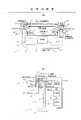
图1示出气体驱动的压缩机的一个实施例,它包括一个液体活塞;Figure 1 shows an embodiment of a gas driven compressor comprising a liquid piston;
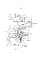
图2示出气体驱动的压缩机的另一个实施例,包括液体和固体两种活塞;Figure 2 shows another embodiment of a gas-driven compressor comprising both liquid and solid pistons;
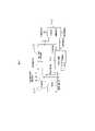
图3示出气体驱动的压缩机的第三实施例,包括一个固体活塞;Figure 3 shows a third embodiment of a gas driven compressor comprising a solid piston;
图4示出气体驱动的压缩机的第四实施例,包括一个固件活塞;Figure 4 shows a fourth embodiment of a gas driven compressor comprising a fixed piston;
图5示出气体驱动的压缩机的第五实施例,包括一个固体活塞;Figure 5 shows a fifth embodiment of a gas driven compressor comprising a solid piston;
图6示出气体驱动的压缩机的第六实施例,包括一个固体活塞;Figure 6 shows a sixth embodiment of a gas driven compressor comprising a solid piston;
图7示出气体驱动的压缩机的第七实施例,包括一个固体活塞;Figure 7 shows a seventh embodiment of a gas driven compressor comprising a solid piston;
图8示出气体驱动的压缩机的一个实施例,包括一个液体活塞;Figure 8 shows an embodiment of a gas driven compressor comprising a liquid piston;
图9是方框图,示出燃气轮机设备的一个实施例,包括一个等温压缩机;Figure 9 is a block diagram illustrating an embodiment of a gas turbine plant, including an isothermal compressor;
图10是方框图,示出另一个装入等温压缩机的燃气轮机设备的另一个实施例;Fig. 10 is a block diagram showing another embodiment of a gas turbine plant incorporating an isothermal compressor;
图11示出烧煤或烧其它燃料装置的实施例,装有等温压缩机和空气涡轮机;Figure 11 shows an embodiment of a coal-burning or other fuel-burning plant, equipped with an isothermal compressor and an air turbine;
图12是方框图,示出包括气体涡轮机和空气涡轮机的燃气轮机设备的另一个实施例;Figure 12 is a block diagram illustrating another embodiment of a gas turbine plant comprising a gas turbine and an air turbine;
图13a示出贮存更冷压缩气体的装置;Figure 13a shows a device for storing colder compressed gas;
图13b示出回收贮存的压缩气体以产生动力的装置;Figure 13b shows a device for recovering stored compressed gas to generate power;
图14是方框图,图示出两种能量贮存装置的设置;Figure 14 is a block diagram illustrating two arrangements of energy storage devices;
图15示出热动力压缩机和附加发电设备的一个实施例;Figure 15 shows an embodiment of a thermodynamic compressor and additional power generating equipment;
图16示出热动力压缩机和附加发电设备的另一个实施例;Figure 16 shows another embodiment of a thermodynamic compressor and additional power generating equipment;
图17示出热动力压缩机与附加发电设备的另一个实施例;Figure 17 shows another embodiment of a thermodynamic compressor and additional power generation equipment;
图18示出热动力压缩机与附加的发电设备的另一个实施例;Figure 18 shows another embodiment of a thermodynamic compressor with additional power generating equipment;
图19示出热动力压缩机与附加的发电设备的另一个实施例;Figure 19 shows another embodiment of a thermodynamic compressor with additional power generating equipment;
图20是方框图,示出从排放气体中回收蒸气的系统;Figure 20 is a block diagram illustrating a system for recovering vapor from exhaust gases;
图21是方框图,示出包括热动力压缩机的封闭循环燃气轮机设备的一个实施例;Figure 21 is a block diagram illustrating an embodiment of a closed cycle gas turbine plant including a thermodynamic compressor;
图22是方框图,示出发电设备的一个实施例,发电设备包括热动力压缩机和用于回收剩余热量的空气涡轮机;Figure 22 is a block diagram illustrating an embodiment of a power plant comprising a thermodynamic compressor and an air turbine for recovering surplus heat;
图23示出封闭和开放的循环热动力压缩机的实施例,其中,采用喷射热液体的方法提供热量;Figure 23 shows an embodiment of a closed and open cycle thermodynamic compressor in which heat is provided by injection of hot liquid;
图24示出装入发电和气化循环系统中的热动力驱动压缩机的一个实施例;Figure 24 shows an embodiment of a thermodynamically driven compressor incorporated into a power generation and gasification cycle;
图25示出装入发电和气化循环系统中的气体驱动压缩机的一个实施例;Figure 25 shows an embodiment of a gas-driven compressor incorporated into a power generation and gasification cycle;
图26示出包括两个可替换的能量贮存装置的热动力压缩机的一个实施例。Figure 26 shows an embodiment of a thermodynamic compressor including two replaceable energy storage devices.
(气体驱动的液体活塞压缩机)/(对称)(gas driven liquid piston compressor)/(symmetrical)
参考图1,通常用1表示的液体活塞等温压缩机包括一个通常为U形的长导管2,该导管有一个水平的或近似水平的细长的直线形中间区段3和两个向上垂直延伸的臂4和5。导管2部分地填充水或某种其它液体,从而形成一个液体活塞7。导管2具有足够的长度和直径,使液体活塞具有控制压缩率所需要的质量。垂直的臂4和5中形成室9和11。每个室设置许多个入口和出口,用于控制进出每个室的空气。口13和15具有阀门17和19,以便允许冷压缩气体从每个室中抽出来。口21和23具有阀门25和27,使质量受控的热压缩气体能够进入每个室,而口29和31受阀门33和35控制,用于使附加量的气体进入每个室。每个室9和11设置了一个额外的口37和39,以便能够向每个室中注入液体喷雾。喷雾注射泵43、44连接到相应的喷雾注射口37、39上。导管2的中间区段3中形成一个出口41,连接到每个泵43、44上,用于将液体从液体活塞供应到口37和39上,以便喷雾。在本实施例中,每个泵都是正排量泵,其中,当液体活塞正在室9、11之外移动的压缩机运行周期期间,液体由活塞板46、48抽入泵室40、42中;当液体活塞移入室9、11中而气体在室9、11中受到压缩时,活塞板46、48连续地迫使液体流出泵室40、42。冷却器45连接在出口41和泵43、44之间,以便在液体作为喷雾注入每个室9和11之前冷却从液体活塞抽出的液体。Referring to Figure 1, a liquid piston isothermal compressor generally indicated at 1 comprises a generally U-shaped
设置了一个用于液体喷雾的水池或水箱51,以便补充在水分分离器47、49中损失的液体,从而使液体活塞的总量在运行期间保持恒定。需要时,水分分离器47、49收集的液体可以通过水箱51返回到液体活塞或喷雾中。液体的水箱51在压缩机起动期间也为喷雾提供液体。A reservoir or tank 51 for liquid spray is provided to replenish liquid lost in the
可以设置浮子50和52,以漂浮在每个室9、11中的液体活塞的表面上,浮子可以由一种多孔的或纤维状的材料构成,液体活塞中使用的液体能够通过浮子扩散。浮子可以是刚性的或柔性的。浮子抑制活塞表面的波浪并阻止液体的夹带物进入冷压缩气体的入口。此外,浮子50、52的多孔性便于从液体喷射流来的液体与活塞中的液体重新结合。
在运行中,从外部气源如常规的旋转式压缩机来的一定量热压缩气体通过入口21注入室9内。此时阀门17和33已经关闭,而液体活塞7位于室9中其冲程的顶部。热压缩空气在室9中膨胀,导致液体活塞7向着长管2的相对端部加速。因为气体膨胀时变冷,所以气体的热能和压力能转变为活塞7的动能。当气体的压力下降到大气压时(或下降到可以利用相对未增压的附加气体的某种其它压力时),阀门33打开,使一定体积的附加气体通过口29进入。液体活塞7继续运动,将气体抽入室9的膨胀体积中。In operation, a quantity of hot compressed gas is injected into
当液体活塞7位于室9中其冲程的顶部时,室11包含一定体积的气体,包括早先作为一定量热压缩气体通过口23引入的一定量的冷膨胀气体和通过口31引入的附加量的相对未增压气体。当液体活塞7从室9中移出而进入室11时,室11中的气体受到压缩。当气体受到压缩时,液体以小液滴形式喷入室11,使气体保持在近似恒定的温度。喷雾中的液体通过气体空间降下并与形成液体活塞7的液体混合。在本实施例中,喷雾液体从管子2的液体中抽出并利用泵43和44通过冷却器45泵回喷雾入口37和39中。When the
在压缩的一定阶段,室11中的气体将达到所需的压力,此时液体停止注入,而阀门19打开,使气体能够从室中流出。分离器47和49用于除去气体中夹带的任何液体。At a certain stage of compression, the gas in
当室11中的液体活塞7达到其冲程的顶部时,出口阀门19关闭,阀门27打开,将一定量的热压缩气体注入室11中,以便将液体活塞7推到管子2的另一端。同时,阀门33关闭,而室9中由通过口21进入的一定量冷膨胀气体和通过口29进入的一定量补充气体组成的一定体积的气体在室9中受到压缩。当气体受到压缩时,液体以小液滴形式喷入室9,使气体保持在近似恒定的温度。喷雾中的液体通过气体空间降下并与形成液体活塞7的液体混合。在压缩的一定阶段,气体将达到所需的压力,此时阀门17打开,使气体能够从室中流出。气体通过分离器47,以除去气体中夹带的任何液体。当液体活塞达到室9中其冲程的顶部时,出口阀门13关闭,而另一定量的热压缩气体注入留在室9中的残余小体积。这部分气体推动液体活塞7回到管子2的另一端,于是周期受到重复。When the
在稳定的运行中,当液体高度达到室9和11中其行程的顶部时,热压缩气体入口阀门25和27定时打开。当一个预定体积的气体进入一个室时,它们重新关闭。当液体活塞下降一个预定距离时,这种情况就可能发生了。In steady operation, when the liquid level reaches the top of its travel in
只有在液体活塞正移入室9和11中的一个的那部分周期期间,冷压缩气体出口阀门17和19才打开。当系统中的压力超过出口管的工作压力时阀门打开,但在热气体入口阀门25和27打开之前关闭。可以使用单向阀(止回阀),仅仅当液体活塞在该特定的室内正向上运动时,它们才受到控制而运行。当相应的室9或11中的压力下降到低压气体源的压力之下时,低压气体入口阀门33和35就打开。单向阀可以用于此目的。Cold compressed
阀门的操作可以由压力决定,而水的高度可以变化。就压力而言,可以使用一个内部机械系统,如一个单向阀存在的系统。另一种办法是,可以使用压力传感器,以产生一个电信号,该电信号可以用来触发一个阀门驱动器。就液体高度而言,虽然一个机械系统是可能的,但产生电信号的传感器是一种更为实用的替代方法。液体高度传感器可以用许多不同方式来工作,如浮子浮标的控测,使用电导计或电容计,光学方法或使用超声波技术。阀门本身可以用电或压缩空气来驱动(即作为动力)。The operation of the valve can be determined by the pressure, while the height of the water can be varied. As far as pressure is concerned, an internal mechanical system can be used, such as a system where a non-return valve exists. Alternatively, a pressure sensor can be used to generate an electrical signal that can be used to trigger a valve actuator. As far as liquid level is concerned, while a mechanical system is possible, a sensor producing an electrical signal is a more practical alternative. Liquid level sensors can work in many different ways, such as control of buoy buoys, using conductivity or capacitance meters, optical methods or using ultrasonic technology. The valve itself can be actuated (i.e. powered) by electricity or compressed air.
液体喷雾系统用来产生大量的处于特定大小范围的小液滴,它们使液体和气体之间的热交换达到最大,而产生喷雾的动力消耗减到最小。从或者利用重力或者利用分离器47和49的作用来从气体中分离小液滴的观点看,同样重要的是小液滴不能太小。分离器除去在出口13和15的另一侧上被向上载带进入支管的任何小液滴。分离器可以采用各种类型。例如,可以使用惯性式分离器或离心式分离器或这两种分离器的某种结合。Liquid spray systems are used to generate a large number of small droplets in a specific size range, which maximize the heat exchange between the liquid and the gas, while minimizing the power consumption of the spray. From the standpoint of separating the droplets from the gas either by gravity or by the action of the
喷雾泵43和44使水循环,从管子2经过外部的冷却器45和注射喷雾口37和39回到管子2中。为此目的可以使用一台正排量泵,以便当室9或11中的压力差变化时使流速保持恒定。正排量泵可以是一种活塞型泵,它可以定时工作,与液体活塞7的运动同相位,使得只有在压缩气体时产生喷射。在这种情况下,不需要用阀门来控制喷雾的注射。另一种办法是,如果使用离心泵或混流泵并连续运行,那么就需要喷雾阀门。外部冷却器45排除被液体喷雾吸收的热量。降低喷雾温度能减少压缩一定量气体所需的能量。为了使喷雾能达到尽可能最低的温度,喷雾液体紧接在喷射之前通过冷却器。冷却可以通过强制通风空气冷却、使用冷却塔或从湖、河、海中再循环水的办法来进行。Spray pumps 43 and 44 circulate water from
在每个室中漂浮在液体活塞表面上的浮子50和52抑制波浪并限制液体的夹带物进入冷压缩气体入口。使用浮子的优点是,阻止液体的夹带物可以使液体活塞在一定时间内工作更多周期。因此,这将增加一定尺寸的压缩机的冷压缩空气的产量。
液体/固体活塞气体驱动式压缩机Liquid/Solid Piston Gas Driven Compressor
除了可以用液体形成大质量活塞外,活塞质量也可以用固体物质形成。可以选用密度比液体高得多的固体物质,从而可以有利地大大缩小压缩机的尺寸。活塞可以完全用固体物质制成,也可以包括多个固体活塞和液体活塞的联用。图2表示一种同时具有液体活塞和固体活塞的气体压缩机。In addition to forming massive pistons from liquids, piston masses can also be formed from solid matter. A solid material having a much higher density than a liquid can be selected, thereby advantageously allowing a considerable reduction in the size of the compressor. The piston can be made entirely of solid matter, or it can include a combination of solid and liquid pistons. Figure 2 shows a gas compressor with both liquid and solid pistons.
参考图2,压缩机1包括一个通常为U形的导管2,部分填充形成液体活塞7的液体。固体活塞55、57由导管2的每个支臂4、5中的液体活塞支承。每个臂4、5为细长的直线形,设置得使固体活塞55、57能自由地进行进出室9、11的垂直直线运动。Referring to FIG. 2 , the compressor 1 comprises a generally
固体活塞55、57的密度大于液体活塞7中液体的密度,使得包括固体和液体组成部分的组合活塞的总尺寸可以相当紧凑。密封固体活塞55、57和导管2的臂4、5之间的间隙用的密封件56、58设置在固体活塞55、57的底部上面并靠近底部。虽然密封件56、58的目的是防止液体从固体活塞55、57下面逸出,但不可避免地会发生某些泄漏,在这种情况下必须补充漏失的液体。这一点可以通过将液体直接泵入包含液体活塞的导管区段来做到。The density of the solid pistons 55, 57 is greater than the density of the liquid in the
固体活塞55、57方便地抑制了液体活塞7表面的界面扰动,同时防止液体的夹带物从液体表面进入气体。但是,固体活塞55、57及其相应的密封件56、58将防止液体喷雾中使用的液体与液体活塞中的液体相结合。因此,喷雾所用的液体由单独的液体源供给,而不是如上述实施例那样由液体活塞本身供给。在现在的实施例中,液体保持在水箱或水池51中,后者将液体供应给喷雾注射泵43和44。喷雾液体通过活塞55、57的作用从室9、11中除去,固体活塞简单地将液体连同等温压缩气体一起通过相应的压缩气体出口13、15推出。液体而后在一个外部水分分离器47中与压缩气体分离。在水分分离器47中分离出的液体通过一个或多个冷却器45返回水箱51,等待再循环。The solid pistons 55, 57 conveniently suppress interfacial perturbations on the surface of the
除了将喷雾液体从室中除去的方式以外,图2中表示的气体压缩机的运行基本上与上述参考图1的压缩机的运行相同。The operation of the gas compressor shown in Figure 2 is substantially the same as that described above with reference to Figure 1, except for the manner in which the spray liquid is removed from the chamber.
到目前为止所说明的压缩机基本上都是对称型的,在于它们都有一个在两个室之间来回驱动的活塞,在每个室中发生同样的过程,即交替的气体膨胀和压缩。但是,在另一种实施例中,压缩可以只在活塞的一侧进行,使得压缩只通过活塞沿一个方向的位移来完成。同样,将动能传送给活塞以用于气体压缩的热压缩气体的膨胀也可以只在活塞的一侧产生,也就是在压缩的同一侧或在相反的一侧。这样一种实施例可以称为非对称性的。The compressors described so far are basically of the symmetrical type in that they have a piston driven back and forth between two chambers in which the same process takes place, namely the alternating expansion and compression of the gas. However, in an alternative embodiment, compression may be on only one side of the piston, such that compression is accomplished by displacement of the piston in one direction only. Likewise, the expansion of the hot compressed gas, which transfers kinetic energy to the piston for gas compression, can also occur on only one side of the piston, ie on the same side as the compression or on the opposite side. Such an embodiment may be referred to as asymmetric.
在一种具有液体活塞的非对称性压缩机中,管子可以制成图1和图2所示的“U”形或制成“J”形。管子的一条臂可以构成压缩室,而另一条臂可以是开放的端部并暴露于大气压,或者是封闭的,其中包封了一个气体空间。在运行中,一定量的热压缩空气注入室内,在那里膨胀和冷却,迫使液体活塞移向管子的另一端。气体的压力和热能转化为液体活塞的动能,而当液体活塞运动时,一定体积的相对低压的气体能够进入室内。当液体活塞在管子的另一端中升高时,如果管子的端部是开放的,那么动能就转换成为由于活塞在管子中的高度而产生的势能;如果管子的端部是封闭的,那么动能就转换成为由于液体活塞的高度而产生的势能和液体活塞上方压缩气体的压力和热能的复合。后一种情况更好,因为管子的臂不需要很高。热能而后转换为活塞沿压缩室方向的动能。如果封闭管子端部处的气体是绝热压缩的,那么当液体活塞反向运动时,气体的势能将重新转换为动能,并进入压缩室压缩气体体积。通过使液体喷雾,气体受到等温压缩。In an asymmetrical compressor with a liquid piston, the tubes can be made in a "U" shape as shown in Figures 1 and 2 or in a "J" shape. One arm of the tube may form the compression chamber, while the other arm may be open ended and exposed to atmospheric pressure, or closed, enclosing a gas space. In operation, a volume of hot compressed air is injected into the chamber where it expands and cools, forcing the liquid piston to move towards the other end of the tube. The pressure and heat energy of the gas is converted into the kinetic energy of the liquid piston, and when the liquid piston moves, a certain volume of relatively low-pressure gas can enter the chamber. As the liquid piston rises in the other end of the tube, if the end of the tube is open, the kinetic energy is converted into potential energy due to the height of the piston in the tube; if the end of the tube is closed, the kinetic energy It is converted into the compound of the potential energy due to the height of the liquid piston and the pressure and heat energy of the compressed gas above the liquid piston. The latter case is better, since the arms of the pipe don't need to be very high. The thermal energy is then converted into kinetic energy of the piston in the direction of the compression chamber. If the gas at the end of the closed tube is compressed adiabatically, then when the liquid piston moves in reverse, the potential energy of the gas is converted back into kinetic energy and enters the compression chamber to compress the gas volume. By nebulizing the liquid, the gas is subjected to isothermal compression.
(固体活塞气体驱动式压缩机)/(非对称型)(Solid piston gas driven compressor)/(Asymmetric type)
如上所述,使用由高密度物质制成的固体活塞以减小压缩机的体积,可能是有利的。图3表示一种具有单个固体活塞的压缩机的实施例,这种压缩机被设计成以非对称模式运行。As mentioned above, it may be advantageous to use a solid piston made of a high density material to reduce the volume of the compressor. Figure 3 shows an embodiment of a compressor with a single solid piston designed to operate in an asymmetrical mode.
参考图3,气体压缩机包括一个含有待压缩气体的上室8,基本上垂直地设置在下室10的上方。一个由固体物质组成的活塞12自由地上下移动,进出上下室8、10。上室8具有一个由气体入口阀33控制的气体入口29和一个由气体出口阀17控制的压缩气体出口13。液体喷雾注射口37用于将液体喷雾注射到上室8中。下室10具有一个由气体入口阀27控制的气体入口23和一个由气体出口阀26控制的气体出口24。Referring to FIG. 3 , the gas compressor includes an
现在说明压缩机的一个典型的运行周期,从固体活塞12处于静止状态并由压缩气体垫支承在紧靠下室10的底部的上方开始。A typical operating cycle of the compressor will now be described, starting with the
此时,上室8包含一定量的等待压缩的新鲜气体,而气体入口阀33和出口阀17是关闭的。At this time, the
从一个合适的气体源如常规的压缩机来的一定量的热压缩气体通过气体入口23注入下室10。热压缩空气膨胀,将动能传送给活塞并迫使活塞12向上进入上室8。当活塞12移入上室8时,上室中的气体受到压缩。在压缩期间,液体通过喷雾注射口37喷入上室8,以冷却气体,使得压缩可以基本上是等温的。在活塞12向上运动期间的某些时间,下室10中的气体入口阀27关闭,而下室中的气体绝热膨胀。A quantity of hot compressed gas is injected into lower chamber 10 through
当上室8中的气体达到一定压力时,压缩气体出口阀17打开,液体喷雾停止,压缩气体连同喷雾液体一起通过气体出口13从室中流出。当活塞12达到上室8中活塞冲程的顶部时,压缩气体出口阀17关闭,上室8中的剩余气体在固体活塞进入室的顶部处静止位置之前可以起吸收固体活塞的动能的作用。这部分剩余气体受到绝热压缩,因此其中贮存的能量可以通过允许气体绝热膨胀来释放,从而将动能传送给沿另一方向的活塞12,使其移出上室外。When the gas in the
一旦活塞12反转方向,下室10中的气体出口阀门26打开,下室中的较冷膨胀气体通过气体出口24排出。当上室中的压力下降到气体入口压力时,上室8中的气体入口阀33打开,而当活塞12向下移到上室外时,相对低压的气体就流入上室8内。Once the
当活塞12接近下室10的底部时,气体出口阀26关闭,下室中的剩余气体受到绝热压缩,延缓了活塞的向下运动,并在活塞12和室的底部之间起气垫的作用。气体出口阀门26的关闭时间可以这样预定,使得下室中气体的压力在活塞反转时等于热压缩气体的入口压力。当活塞到达下室中的静止位置时,压缩气体入口27打开,一股新鲜的热压缩气体注入下室,于是周期就开始重复。When the
在本实施例中,单独的重力就可以形成一种将活塞沿一个方向的动能转换成沿另一方向给活塞传送动能的势能装置。在这种情况下,压缩机的运行频率将受到重力恢复的限制。但是,可以通过提供某种机构在比重力提供的速率更大的速率下吸收和传送活塞的动能,例如,如上所述,在活塞上方提供一个压缩气袋,该气袋在活塞于上室中反转运动期间膨胀。In this embodiment, gravity alone can form a potential energy device that converts the kinetic energy of the piston in one direction to transmit kinetic energy to the piston in the other direction. In this case, the operating frequency of the compressor will be limited by gravity recovery. However, the kinetic energy of the piston can be absorbed and transmitted at a rate greater than that provided by gravity by providing some mechanism, for example, providing a pocket of compressed air above the piston, in the upper chamber of the piston, as described above. Swell during inversion.
(固体活塞气体驱动式压缩机)/(对称型)(Solid piston gas driven compressor)/(Symmetrical type)
在另一种气体压缩机的实施例中,一个固体活塞被设置成沿垂直方向直线运动,也可以设置机构既向下室也向上室注射热压缩气体,使得通过气体的注射和膨胀沿两个方向给活塞传送能量。同样,可以修改压缩机,使得等温压缩气体既在上室也在下室中产生。其次,压缩机可以这样设置,使得在热压缩气体膨胀之后一个附加量的相对低压的气体被引入每个室,使得压缩机产生比驱动它所需的更大量的压缩气体。这样一种压缩机在活塞的两边产生同样的过程这个意义上说是对称的,但是在驱动力和恢复力受重力的偏置这个意义上说是非对称的。这种形式的气体压缩机的一个例子示于图4。In another embodiment of the gas compressor, a solid piston is arranged to move linearly in the vertical direction, it is also possible to arrange the mechanism to inject hot compressed gas into both the lower chamber and the upper chamber, so that through the injection and expansion of the gas, both Direction transmits energy to the piston. Likewise, the compressor can be modified such that isothermally compressed gas is produced in both the upper and lower chambers. Second, the compressor can be set up so that an additional quantity of relatively low pressure gas is introduced into each chamber after the expansion of the hot compressed gas, so that the compressor produces a larger quantity of compressed gas than is required to drive it. Such a compressor is symmetrical in the sense that the same process occurs on both sides of the piston, but asymmetrical in the sense that the driving and restoring forces are biased by gravity. An example of this form of gas compressor is shown in Figure 4.
参考图4,气体压缩机1包括一个基本上设置在下室11垂直上方的上室9和一个上下自由移动而进出上下室的固体活塞12。在活塞12和室壁之间设置了密封机构14,用于防止气体从每个室泄漏。每个室9、11各有一个由压缩气体入口阀25、27控制在热压缩气体入口21、23,用于将一股热压缩气体引入室内;各有一个由压缩气体出口阀17、19控制的压缩气体出口13、15,用于使冷压缩气体能够从室内引出;各有一个由气体入口阀33、35控制的气体入口29、31,用于使附加量的气体进入室内;以及各有一个液体喷雾注射入口37、39,用于在压缩期间将一股液体喷雾引入室内。Referring to FIG. 4, the gas compressor 1 includes an
喷入每个压缩室的液体受到回收并重新循环。液体回收系统包括一个连接在每个压缩气体出口13、15上的水分分离器47、49,用于从冷压缩气体中分离喷雾液体;一个连接在每个水分分离器47、49上的冷却系统45,用于冷却喷雾液;以及连接在冷却系统和每个喷雾注射口37、39之间的独立的泵43、44,用于从水分分离器47、49泵出液体,通过冷却系统45进入压缩室9、11。泵最好设计成为当压缩室中的压力在压缩期间增大时能以恒定速率将喷雾液体泵入室内。设置了一个联管箱51,用来补充没有回收的液体或从回收系统中损失的液体。Fluid injected into each compression chamber is recovered and recirculated. The liquid recovery system comprises a
图4所示的气体压缩机1的一个典型的运行周期进行如下:由固体活塞12暂时地静止在下室11的底部的紧上方并由压缩气体垫支承开始。此时,上下室9、11中的所有气体入口和出口阀都关闭,上室中包含一团早先通过热压缩气体入口21引入的冷膨胀气体,还有一团早先通过气体入口29引入的附加气体。A typical operating cycle of the gas compressor 1 shown in Figure 4 proceeds as follows: It begins with the
当活塞12在下室11中停止下来的时候,热压缩空气入口阀27打开,一股热压缩空气引入下室。在预定的一段时间后,入口阀关闭。而后气体绝热膨胀,迫使活塞12离开下室11进入上室9。这样,热压缩空气的膨胀能量转换成块状固体活塞的动能,活塞被向上推并获得势能。转过来,活塞的动能部分转换成上室9中压缩空气的压缩能量。当活塞12移入上室9中时,上室9中的空气受到压缩,同时冷的液体喷雾被注入上室9,以防止气体受热,使压缩可以近于等温。When the
引入下室11的热压缩气体的绝热膨胀沿上室9的方向将足够的动能传送给活塞12,使得下室11中膨胀气体产生的作用在活塞12上的向上推力变成小于作用在活塞12上的向下力时(向下力是由于活塞的质量与上室中气体的重量和压力而引起的),活塞12由于其惯性很大,将继续向上运动进入上室9内。当下室中空气的压力下降到低于附加气源的压力时,下室中的空气入口阀35打开,而当活塞继续向上运动时,一定量的附加气体被引入下室。The adiabatic expansion of the hot compressed gas introduced into the
当上室中的气体压力达到所需值时,压缩空气出口阀17打开,冷压缩空气连同喷雾液体通过压缩空气出口13从上室流出。压缩气体通过水分分离器47,在那里从压缩空气中除去喷雾液体,提取的液体进入冷却器45,在冷却器中冷却后重新用于液体喷雾中。When the gas pressure in the upper chamber reaches the required value, the compressed
当活塞12在上室9中达到其行程极限时,压缩空气出口阀17关闭,而上室中残留的任何剩余气体将使活塞12处于静止。气体出口阀17的关闭最好这样定时,使得在上室9中活塞反转时,室中气体压力等于热压缩气体入口压力。在活塞停止下来时,下室中的气体入口阀35关闭,因此此时下室11中的所有气体入口和出口阀都关闭。而后热压缩气体入口25打开,一股热压缩气体通过热压缩气体入口21引入上室。在预定时间后,气体入口阀关闭,而后气体绝热膨胀,迫使活塞12移出上室9进入下室11。这样,上室中气体膨胀的能量转换成活塞沿下室方向的动能。活塞由于其质量和高度而产生的势能同时转换成动能。下室中气体(包括一定量的早先通过热压缩气体入口23引入的冷膨胀气体和一定量的通过气体入口31引入的附加气体)在活塞12运动时被压缩到下室11中,同时一股液体的喷雾被射入下室以便吸收气体压缩产生的热量,从而防止气体温度升高,使得压缩过程可以近似于等温。这样,活塞的动能转换成下室11中气体的压缩能。When the
当上室9中的气体压力下降到附加气体的供应压力以下时,气体入口阀33打开,当活塞12继续向下运动而移出上室9时,一定量的附加气体被引入上室9。When the gas pressure in the
当下室11中的气体压力达到所需值时,压缩气体出口阀19打开,压缩气体连同喷雾液体从下室通过压缩气体出口15引出。压缩气体和喷雾液体通过水分分离器49,在那里从压缩气体中除去喷雾液体,而后将液体通入冷却器45,然后重新用于液体喷雾。When the gas pressure in the
刚巧在活塞12达到下室11中其行程极限之前,压缩气体出口阀19关闭,将剩余的压缩气体留在下室中,其作用使活塞停止下来。气体出口阀的关闭时间最好这样预定,使得下室中的气体压力在活塞反转时等于热压缩气体入口压力。当活塞停下来时,上室中的气体入口阀33关闭,使上室9中的所有气体入口和出口阀都关闭。热压缩气体入口阀27打开,将一股新鲜的热压缩气体引入下室。而后周期开始重复。Just before the
如此所述,图4所示的垂直直线性气体压缩机由于向着下室给恢复力加偏压的活塞重量而仅仅是近似地对称的。通常,上下室中的压缩气体出口压力最好相等,使得压缩气体在整个周期中能够以恒定压力供应。其次,上下室中的热压缩气体入口压力最好也是相等的。通过在上下室中供应不同量的气流可以达到上述每个目的。气体进入上下室的流量可以按照气体出入口的大小和/或气体出入口阀门打开期间的时间长短来控制。As such, the vertical linear gas compressor shown in Figure 4 is only approximately symmetrical due to the weight of the piston biasing the restoring force towards the lower chamber. In general, the compressed gas outlet pressure in the upper and lower chambers is preferably equal so that the compressed gas can be supplied at a constant pressure throughout the cycle. Second, the hot compressed gas inlet pressures in the upper and lower chambers are also preferably equal. Each of the above objects can be achieved by supplying different amounts of gas flow in the upper and lower chambers. The flow of gas into the upper and lower chambers can be controlled according to the size of the gas inlet and outlet and/or the length of time during which the gas inlet and outlet valves are open.
由于当活塞停止下来时活塞和上室顶部之间最后始终存在一定间隙,因此并非所有的上室中的喷雾液体都被排出,有一些液体始终留在上室中。但是,不希望剩余的液体严重影响压缩机的性能。在每个压缩周期后下室中也可以残留一些液体,但是,通过(例如)改变下室底部的形状和选定气体出入口的位置可以有助于除去喷雾液体,使得可以将液体排出室外。Since there is always a certain gap between the piston and the top of the upper chamber when the piston stops, not all of the spray liquid in the upper chamber is discharged, and some liquid remains in the upper chamber all the time. However, it is undesirable for the remaining liquid to seriously affect the performance of the compressor. Some liquid may also remain in the lower chamber after each compression cycle, however, removal of sprayed liquid may be facilitated by, for example, changing the shape of the bottom of the lower chamber and the location of selected gas inlets and outlets so that the liquid can be vented out of the chamber.
图5表示在一个燃气轮机设备中采用的具有一个直线形垂直运动固体活塞的气体压缩机的另一个实施例。在这个实施例中,上室中产生冷压缩空气,在这一方面,该压缩机与图3和图4中表示的实施例相似。但是,与上面的实施例不同,下室是关闭的并包含一团气体,这团气体起弹簧的作用,以便当活塞向下行进移出上室时吸收活塞的动能,并将动能重新传送给沿相反方向进入上室的活塞。Figure 5 shows another embodiment of a gas compressor having a linear vertically moving solid piston employed in a gas turbine plant. In this embodiment, cold compressed air is produced in the upper chamber, and in this respect the compressor is similar to the embodiment shown in FIGS. 3 and 4 . However, unlike the above embodiment, the lower chamber is closed and contains a mass of gas that acts as a spring to absorb the kinetic energy of the piston as it travels down and out of the upper chamber and retransmits the kinetic energy to the The piston that enters the upper chamber in the opposite direction.
(固体活塞气体驱动式压缩机)(solid piston gas driven compressor)
(非对称型)(asymmetric type)
参考图5,气体压缩机1包括一个基本上位于下室11垂直上方的上室9和一个设置在两室之间自由振荡的固体活塞12。压缩机1在活塞和室壁之间包括密封机构14,以防止气体从任何一个室中泄漏。上室9有一个由阀门25控制的热压缩气体入口21,允许热压缩气体进入室内;一个由阀门17控制的冷压缩气体出口13,允许冷压缩气体从室内引出;以及一个由阀门33控制的气体入口29,允许当室内的气压降到一定值以下时一定量的附加气体进入上室9。Referring to FIG. 5, the gas compressor 1 includes an
上室中同时形成一个喷雾注射口37′,用于在压缩期间注射液体喷雾。一个回收系统设置用于在压缩后从压缩室回收和冷却喷雾液体。回收系统包括连接上室的出口13的水分分离器47,用于从离开室的冷压缩空气中除去喷雾液体;一个连接水分分离器47的冷却系统45,用于冷却喷雾液体;以及一个连接在冷却系统45和上室9的喷雾注射口13之间的泵43,用于从水分分离器47泵出液体,通过冷却系统45并经过一个喷雾嘴(未图示)喷入上室9。设置了一个含有喷雾液体的联管箱,用于补充没有回收的或从回收系统损失掉的液体。A spray injection port 37' is also formed in the upper chamber for injecting a liquid spray during compression. A recovery system is provided for recovering and cooling the spray liquid from the compression chamber after compression. The recovery system comprises a
下室11包含一定体积的气体,它们尽可能永久性地密封在室11中。一些气体可能会不可避免地通过固体活塞和室壁之间的密封件14从下室泄漏,但可以采取措施补充从下室损失的气体,例如在下室中设置一个由阀门控制的气体入口,允许从一个合适的增压源补充气体。The
图5表示的压缩机的一个典型操作周期进行如下,从固体活塞12暂时地停止在上室9中其冲程的顶部开始。此时,压缩气体出口阀17和气体入口阀25、33被关闭,而室内可包含一团压缩气体。A typical operating cycle of the compressor represented in Figure 5 proceeds as follows, starting with the
当活塞反转方向时,热压缩气体入口阀25打开,引入一股热压缩气体到上室中。在一个预定的时间间隔后,热压缩气体入口阀25关闭,同时热压缩气体绝热膨胀,将活塞12向下推出上室。当活塞12移入下室11时,下室中的气体受到绝热压缩,使得沿下室方向传送给活塞12的动能作为压力能和热能被气体所吸收,热能导致气体温度随之升高。当上室9中的膨胀气体的压力降低到附加气体供应源的入口压力时,气体入口阀33打开,随着活塞12的继续向下运动,一定量的附加气体被引入上室。当活塞的所有动能都已被下室中的气体吸收时,活塞暂时停止下来,而上室中的气体入口阀33关闭。而后下室中现在已热了的压缩气体绝热膨胀,将动能向着上室9方向传送给活塞12。当活塞移回到上室9中时,上室中的气体受到压缩,上室中的气体包括先前作为热压缩气体通过气体入口13引入的气体量和通过气体入口29引入的相对低压的气体的附加量。当气体受到压缩后,液体以小液滴的形式喷入上室,以便从气体吸收压缩热,使得压缩过程可以近似地等温。当上室中的气体温度达到喷雾液体的温度后,预定时间的喷雾就开始注射。当上室9中的气体压缩达到所需值时,压缩气体出口阀17打开,冷压缩气体连同喷雾液体一起通过气体出口13从上室中引出。压缩气体和喷雾液体通到水分分离器47,在那里从气体中除去喷雾液体。When the piston reverses direction, the hot compressed
在活塞到达上室中其行程的极限之前,压缩气体出口阀17关闭,而上室中剩余的气体有助于活塞停止下来。当活塞停止下来时,热压缩气体入口阀25打开,一股新鲜的热压缩气体通过气体入口21引入上室9,以重复下一个周期。Before the piston reaches the limit of its travel in the upper chamber, the compressed
因为这个实施例只有一个室用于产生冷压缩气体,所以压缩气体每周期只生产一次。为了在周期的时间内以更恒定的速率产生气体,还可以设置一或多个这样的气体压缩机,彼此以错开的相位运行。例如,如果再设置一个压缩机,它们的运行周期可以相隔180°。相位的隔开依赖于压缩机如何设置,它可以用来帮助防止由于块状固体活塞的加速和减速而产生的机械振动。Since this embodiment has only one chamber for generating cold compressed gas, compressed gas is produced only once per cycle. In order to produce gas at a more constant rate over the period of the cycle, one or more of these gas compressors may also be arranged to operate out of phase with each other. For example, if there is an additional compressor, their operating cycles can be separated by 180°. Phase separation, depending on how the compressor is set up, can be used to help prevent mechanical vibrations due to the acceleration and deceleration of the massive solid piston.
在具有垂直直线运动的固体活塞的压缩机的另一种实施例中,下室可以修改成产生等温压缩气体,并用于引入热压缩气体,以便沿向上方向将动能传送给活塞。上室可用来封闭一团气体,这团气体受到活塞在向上冲程中的绝热压缩,以吸收活塞的动能,而后膨胀,向下沿下室方向将动能传送给活塞。在这个基本上是图5所示实施例的反转形式的实施例中,活塞沿上室方向的动能转换为上室中气体的压缩能和热能以及由于重力而产生的势能。或者,上室可以完全省去,使得由热压缩气体引入下室而传送给固体活塞的全部动能都转换为由于重力而产生的势能,而后释放为沿相反方向对着下室的动能,以压缩下室中的气体。这样,有利的是,这个特殊的实施例只需要一个室,并不需要补充损失的气体用的与绝热压缩/膨胀室有关的辅助设备。在下室中完成等温压缩的优点是该室可以设计成在除去喷雾液体的过程中利用了由重力提供的势能相助。In another embodiment of a compressor with a solid piston moving vertically, the lower chamber can be modified to generate isothermal compressed gas and used to introduce hot compressed gas to transfer kinetic energy to the piston in an upward direction. The upper chamber can be used to enclose a mass of gas which is adiabatically compressed by the piston during its upward stroke to absorb the kinetic energy of the piston, and then expands to transmit kinetic energy to the piston down the direction of the lower chamber. In this embodiment, which is essentially an inverted version of the embodiment shown in Figure 5, the kinetic energy of the piston in the direction of the upper chamber is converted into compression and thermal energy of the gas in the upper chamber and potential energy due to gravity. Alternatively, the upper chamber can be omitted entirely so that all the kinetic energy transferred to the solid piston by the hot compressed gas introduced into the lower chamber is converted into potential energy due to gravity and then released as kinetic energy against the lower chamber in the opposite direction to compress the gas in the lower chamber. Thus, advantageously, this particular embodiment requires only one chamber and does not require the auxiliary equipment associated with the adiabatic compression/expansion chamber for replenishing lost gas. An advantage of performing the isothermal compression in the lower chamber is that the chamber can be designed to utilize the potential energy provided by gravity to assist in the removal of the spray liquid.
(固体活塞气体驱动式压缩机)/(对称型)(Solid piston gas driven compressor)/(Symmetrical type)
在另一种实施例中,气体压缩机可以包括一个被设置成沿水平面运动的固体活塞。图6表示一个此种实施例的例子,该实施例包括两个沿水平相对的室和一个大的固体活塞,后者被设置成沿直线往复运动而进出每个室。In another embodiment, the gas compressor may include a solid piston arranged to move in a horizontal plane. Figure 6 shows an example of such an embodiment comprising two horizontally opposed chambers and a large solid piston arranged to reciprocate linearly into and out of each chamber.
参考图6,气体压缩机包括两个水平相对的室9、11,每个室有由阀门25、27控制的热压缩气体入口21、23,用于将热压缩气体引入每个室;有由阀门17、19控制的压缩气体出口13、15,用于使压缩气体能够从每个室引出;由气体入口阀35、37控制的气体入口31、33,用于使附加气体能够进入每个室;以及喷雾注射口37′、39,用于将液体喷雾注射进每个室,以控制气体温度。气体压缩机具有一个由耐摩轴承14、16支承的大的固体活塞12,该活塞可在两室9、11之间自由振荡。在活塞和每个室的壁之间设置了一个滑动密封件56、58,以防止气体通过活塞12和室壁之间的间隙泄漏。在这个实施例中,活塞12的两端是弧形的,室9、11的两端也是弧形的。Referring to Fig. 6, the gas compressor comprises two horizontally
设置了一个回收系统,以便在每个室中气体等温压缩之后回收喷雾中使用的液体,并处理液体以便重新用于喷雾。回收系统包括连接到各自的压缩气体出口13、15上的水分分离器47、49,用于从压缩气体除去喷雾液体。出口形成于每个室的下部,以便于除去喷雾液体。水分分离器47、49连接到冷却系统45上,以冷却喷雾液体。每个室有一个泵43、44连接在冷却系统45和喷雾注射口37′、39之间,用于通过冷却系统从水分分离器47、49泵出液体,并通过喷雾注射口返回到每个室中。A recovery system is provided to recover the liquid used in spraying after isothermal compression of the gas in each chamber and to process the liquid for reuse in spraying. The recovery system comprises a
这种实施例的气体压缩机的运行周期进行如下:从活塞12位于右室11中活塞行程的极限位置而室11中所有阀门处于关闭状态开始。右室11包含少量的绝热压缩气体,用于使活塞停止下来。此时,左室包含一定量的气体,包括一定量的先前作为热压缩气体通过热压缩气体入口21引入的冷却的膨胀气体和一定量的先前通过气体入口31引入的相对低压的气体。左室9中的所有阀门都是关闭的。The operating cycle of the gas compressor of this embodiment proceeds as follows: the
在活塞停止下来以后,右室中残留的压缩气体开始膨胀并将活塞12推出右室。同时,热压缩气体入口阀27打开,一股热压缩气体被引入右室。在一定的预定时间间隔后,气体入口阀27关闭。而后热压缩气体绝热膨胀,迫使活塞12离开右室11并进入左室9。这样,膨胀能转换为活塞沿左室9方向的动能。当活塞12移入左室9时,气体受到压缩,同时喷雾形式的液体注入室内,以便在压缩期间冷却气体。After the piston has stopped, the compressed gas remaining in the right chamber begins to expand and push the
当右室11中膨胀气体的压力下降到预定值以下时,气体入口阀37打开,一定量附加的相对低压气体被通过气体入口33引入右室。When the pressure of the inflation gas in the
当左室9中的气体压力达到所需值时,通过口37′注射喷雾就停止,压缩气体出口阀17打开,压缩气体连同喷雾液体一起通过压缩气体出口13从室内引出。压缩气体和喷雾液体通过水分分离器47,在分离器中从气体内除去喷雾液体。而后喷雾液体通过冷却器45,然后重新使用在喷雾中。When the gas pressure in the
在活塞12达到左室9中其行程的极限时,压缩气体出口阀17关闭,室中的剩余气体受到绝热压缩,使活塞暂时停止下来。此时右室11中的气体入口阀37关闭。而后活塞当剩余气体膨胀时反转方向,此时,热压缩气体入口阀25打开,一股新鲜的热压缩气体通过热压缩气体入口21注入左室9。在一定的预定时间间隔后阀门25关闭。而后热压缩气体绝热膨胀,迫使活塞12离开左室9返回到右室11中。When the
右室11中所有的入口阀和出口阀都关闭,室11包含一定量的气体,包括先前作为热压缩气体通过入口23引入的一定量的冷却的膨胀气体和先前通过入口33引入的一定量的相对低压的附加气体。当活塞12移入右室11时,气体受到压缩,同时一股液体喷雾通过喷雾注射口39注入室内,以便在压缩期间冷却气体。All inlet and outlet valves are closed in the
当左室9中的气体压力下降到某预定值,气体入口阀17打开,一定量的相对低压的附加气体通过气体入口13引入左室9。When the gas pressure in the
当右室11中的气体压力达到所需值,压缩气体出口阀19打开,压缩气体连同喷雾液体一起通过出口15从室中引出。而后压缩气体和喷雾液体通过水分分离器49,在那里从压缩气体中除去喷雾液体。液体而后通到冷却器45,在那里受到冷却,然后返回用作喷雾液体。When the gas pressure in the
在活塞到达右室11中其行程的极限之前,压缩气体出口阀19关闭,喷雾注射停止,剩余气体受到绝热压缩,使活塞12暂时停止下来。此时左室9中的所有阀门都关闭,而热压缩气体入口阀27打开,将一股新鲜的热压缩气体引入右室11,气体膨胀,迫使活塞离开右室并进入左室,以重复下一个周期。Before the piston reaches the limit of its stroke in the
也仔细考虑了具有水平移动的固体活塞并具有不同于上述的运行方式的其它形式的气体压缩机。例如,一个室可以用作绝热压缩/膨胀室并包含一团密封的气体,该气体交替地绝热压缩和膨胀,将沿室的方向传送给活塞的动能转换为活塞沿另一方向离开室的动能。这样,室将起与图5所示的下室相似的作用。Other forms of gas compressors having horizontally moving solid pistons and having modes of operation other than those described above are also contemplated. For example, a chamber may act as an adiabatic compression/expansion chamber and contain a sealed mass of gas that alternately adiabatically compresses and expands, converting kinetic energy transmitted to the piston in one direction of the chamber to kinetic energy of the piston leaving the chamber in the other direction . In this way, the chamber will function similarly to the lower chamber shown in FIG. 5 .
因为固体活塞被设置成沿水平面运动,所以必须设置某些机构以支承活塞,同时最好尽可能减小会阻碍活塞水平运动的摩擦力。支承轴承可以是机械轴承,例如特别设计用于支承活塞重量的滚柱轴承。每个轴承支承的活塞重量可以通过增加轴承数目来减少。虽然最好将活塞制造得尽可能紧凑,但是每单位长度和宽度的活塞重量可以通过相应地定活塞的大小来变化。活塞可以是任何形状,可以沿其长度改变截面几何形状和大小。这样,活塞的质量可以沿其长度变化,而且它可以适当地将活塞质量集中在活塞的一部分,使它比另一部分更多。在某些应用中,可以适当地设计支承轴承,使其在活塞的总质量中占有显著的比例。也可以使用其它类型的耐磨轴承来支承活塞,例如那些其运行以磁悬浮或加压流体悬浮的原理为基础的活塞。Since the solid piston is arranged to move in a horizontal plane, some mechanism must be provided to support the piston while preferably minimizing the frictional forces that would hinder the horizontal movement of the piston. The support bearings may be mechanical bearings such as roller bearings specially designed to support the weight of the piston. The weight of the piston supported by each bearing can be reduced by increasing the number of bearings. Although it is preferable to make the piston as compact as possible, the weight of the piston per unit length and width can be varied by sizing the piston accordingly. The piston can be of any shape and can vary in cross-sectional geometry and size along its length. In this way, the mass of the piston can vary along its length, and it is possible to properly concentrate the mass of the piston in one part of the piston so that it has more mass than another. In some applications, the support bearings can be suitably designed to account for a significant proportion of the total mass of the piston. Other types of anti-friction bearings may also be used to support the pistons, such as those whose operation is based on the principle of magnetic levitation or pressurized fluid levitation.
在某些应用中,在压缩室外产生液体喷雾是有利的,这种喷雾使压缩室内的空气或气体在压缩期间保持在近等温状态。喷雾可以在含空气或其它气体的独立外部容器中产生。而后液体喷雾可以在压缩之前与该空气或其它气体一起引入压缩室。In some applications it is advantageous to generate a spray of liquid outside the compression chamber which maintains the air or gas within the chamber at a near isothermal state during compression. The spray can be generated in a separate external container containing air or other gas. The liquid spray can then be introduced into the compression chamber together with this air or other gas prior to compression.
图7表示一种直线型垂直气体压缩机,类似于图5所示的那种,但包括一个在压缩室外部的独立容器,容器中产生在压缩期间冷却气体用的雾并使雾与大气空气混合,然后进入压缩室。参考图7,压缩机同包括一个垂直地设置在下室11上方的上室9和一个自由振荡垂直进出每个室的固体活塞12。上室9有一个由阀门25控制的热压缩气体入口21,用于允许热压缩气体进入室内向下推动活塞12;一个由阀门17控制的冷压缩气体出口13,允许冷压缩气体从室内引出;以及一个由阀门33控制的气体入口29,允许液体喷雾与附加的相对低压气体一起引入室内。气体入口29连接到一个产生雾的独立容器55上。设置了一个气体入口57,允许气体被引入雾发生器55内。Figure 7 shows a linear vertical gas compressor similar to that shown in Figure 5 but including a separate container outside the compression chamber in which a mist for cooling the gas during compression is generated and separated from the atmospheric air Mix, then enter the compression chamber. Referring to Fig. 7, the compressor generally comprises an
从离开压缩室的冷压缩气体分离的液体由泵43重新循环,通过冷却器45返回雾发生器55。液体喷雾可以利用任何常规的方法在雾发生器55内发生,例如利用迫使液体通过一或多个喷雾喷嘴的方法。在活塞12向下运动期间,气体入口阀33打开,气体通过气体入口57引入雾发生器55,将细液滴通过气体入口29扫入压缩室。因为当压缩室中的压力相对低时液体喷雾被引入压缩室,并且因为喷雾被允许在压缩之前而不是在压缩期间产生,所以泵吸液体的功减小了,小液滴在压缩室内在气体中的更好分布应当是可以达到的。通过在压缩室外面形成喷雾,也可能获得更细喷雾。例如,分离出更大的液滴并将它们重新循环而不是将它们注入等温压缩机可能是值得的。也可以采用低压风扇帮助气体吹入雾发生器。雾发生器也可以联用一个机械装置如旋转盘或旋转叶片,用于将小液滴粉碎成细雾。Liquid separated from the cold compressed gas leaving the compression chamber is recirculated by
除了液体喷雾和大气空气引入压缩室的方式外,图7所示的气体压缩机的运行情况与上面参考图5说明的气体压缩机完全相同。The operation of the gas compressor shown in Figure 7 is exactly the same as that of the gas compressor described above with reference to Figure 5, except for the manner in which the liquid spray and atmospheric air are introduced into the compression chamber.
(液体驱动式压缩机)/(液体活塞型)(Liquid Driven Compressor)/(Liquid Piston Type)
上面说明的压缩机的实施例都是用热压缩气体驱动的。驱动压缩的另一种方法是使用液体位差。动能贮存机构可以由一个大的活塞(不管是固体的、液体的还是固液联用的)方便地形成,活塞被设置成将液体的能量转换成气体的压缩能。图8表示一种以此种方式运行的液体活塞等温压缩机。The compressor embodiments described above are all powered by hot compressed gas. Another way to drive compression is to use a liquid head. The kinetic energy storage mechanism may conveniently be formed by a large piston (whether solid, liquid or combined) arranged to convert the energy of the liquid into the compressive energy of the gas. Figure 8 shows a liquid piston isothermal compressor operating in this manner.
参考图8,等温压缩机包括两根管子102和103,每根管子有一个水平设置的中区105和107,而且每根管子包含一个液体活塞109和111。每根管子102和103的一个端区113和115垂直向上延伸,端区中分别形成待压缩气体用的室117和119。每根管子102和103的另一端区形成一个单独的大容器127。Referring to Figure 8, the isothermal compressor comprises two tubes 102 and 103, each tube has a horizontally disposed central zone 105 and 107, and each tube contains a
主流阀129和131设置在管子102和103的水平区段105和107中,以控制从储液器127来的液体流。出口133和135形成于水平区段105和107中,位于主流阀129、131和管子102、103的垂直区段113、115之间。排水阀137和139设置在出口133和135中,以控制从管子102和103排出的液体流。主泵141连接在出口133、135和储液器127之间,以便用通过出口133和135排出的液体重新注入储液器。
如以前一样,对每个室117和119提供液体喷雾,用以冷却压缩气体。每个室117和119设有气体出口147和149,每个出口有一个阀门151和153,允许冷压缩气体从每个室117和119引出。每个室有一个气体入口155和157,允许气体从一个合适的气源进入每个室。As before, a spray of liquid is provided to each
在运行中,储液器的作用是储存加压液体,以提供液流浪涌(波动)来驱动液体活塞109和111。这些浪涌的计时由位于管子102和103内的主流阀129和131控制。当一个主流阀打开时,液体的浪涌通过该阀门流动,驱动液体活塞进入室内并压缩气体。同时,与该室相联结的喷雾喷发,以便在压缩期间冷却气体。当室中的压力达到预定值时,压缩气体的出口阀门就打开了。In operation, the function of the reservoir is to store pressurized fluid to provide surges (waves) of fluid flow to drive the
当液体活塞达到其行程的顶部时,主流阀关闭,排水阀打开。同时气体出口阀关闭而气体入口阀打开,允许低压气体取代排出液体。排出液体由主泵141再循环泵回储液器。When the liquid piston reaches the top of its stroke, the main flow valve closes and the drain valve opens. At the same time the gas outlet valve is closed and the gas inlet valve is opened, allowing low pressure gas to replace the discharge liquid. The drained liquid is recirculated by the
最好是,每根管子中液体活塞109和111的运行计时是这样的,即液体从一根管子返回储液器,而同时液体又从储液器流出,进入另一管子。因此,在一个双管系统中,两根管子中的液体活塞应当互成反相。通常,液体高度上方的气体当流入液流超过流出液流时受到压缩,当流出液流超过流入液流时膨胀。目标是尽可能减小由泵141传送的液位和液流的变化,使得泵的运行能够始终接近其效率最高点。最好是气体的体积绝热地膨胀和收缩。储液器是绝热的,以便在储液器气体压缩时尽可能减小热量。储液器气体并不连接到被压缩的气体上,这两种气体的组成确实不需要相同。有利的是,储液器出来的液体的流动速率受液体活塞贯性的限制,这防止储液器中的气体压力变化太大。Preferably, the timing of the operation of the
主流阀129和131起动液体活塞的运动。当液体泵出压缩室时,这些控制阀门打开。当液体活塞在压缩室中达到其行程的最大点时,这些控制阀门关闭。主要控制阀门是液体驱动等温压缩机的关键部件。管子直径可以十分大,但是重要的是,阀门能够迅速而经常地打开和关闭。阀门需要阻挡也许为8巴的压力。其次的要求是当打开时阀门必须产生尽可能小的流动阻力。还有一个特点是,只有当液体流的方向反转并暂时处于速度为零时阀门才打开或关闭。虽然其它的阀门设计对这项功能是可能的,但阀门最好包括支承在横穿管子截面的许多根棒上的一组隔栅。当隔栅与液流对准时,隔栅的外形将使液流的阻力减到最小。
排液阀137和139被设计成当液体活塞达到其行程的最大范围时打开,当压缩室排液时关闭。这意味着,排液阀的运行与主流阀129和131错开180°的相位。排液阀的类型最好与主流阀相同。
喷雾泵159和161连接在储液器和喷雾口之间,以供应喷雾用的液体。最好是,冷却器163和165连接在喷雾泵159、161和冷却液体的喷雾之间。喷雾泵可以是正排量泵类型的泵,以便保证当压缩室中的压力变化时液流是恒定的。Spray pumps 159 and 161 are connected between the reservoir and the spray port to supply liquid for spraying. Preferably,
到目前为止说明的气体驱动的和液体驱动的等温压缩器之间的主要差别如下。虽然两种类型的压缩器都以同样的物理原理为基础,即使用大的液体和/或固体活塞来进行等温压缩,但主要动力是用不同装置提供的。与液体活塞压缩机相比,气体驱动系统没有浸在主管线的液体中的大阀门。因此在气体驱动系统中液体活塞的摩擦耗能减到最小。图1所示的气体驱动液体活塞压缩机的实施例在液体活塞的每个周期中压缩两个体积的气体,而在液体驱动的压缩机中每周期只压缩一个体积的气体。液体驱动的压缩机通常需要一个大泵作为主要动力源,而气体驱动的压缩机需要一个常规的气体压缩机,例如通常可以连接在气体涡轮机上的那种。The main differences between gas-driven and liquid-driven isothermal compressors described so far are as follows. Although both types of compressors are based on the same physical principle of isothermal compression using large liquid and/or solid pistons, the main power is provided by different means. In contrast to liquid piston compressors, gas driven systems do not have large valves immersed in the liquid in the main line. Therefore, the frictional energy loss of the liquid piston is minimized in the gas driven system. The embodiment of the gas driven liquid piston compressor shown in Figure 1 compresses two volumes of gas per cycle of the liquid piston, whereas in the liquid driven compressor only one volume of gas is compressed per cycle. Liquid-driven compressors usually require a large pump as the primary power source, while gas-driven compressors require a conventional gas compressor, such as the kind that can usually be attached to a gas turbine.
虽然图1、2、8中形成液体活塞的管子的臂大体上是垂直的,而且管子被说明为具有近似水平的中间区段,使管子的形状为U形,但是臂可以以任何角度倾斜,而该U形可以是宽的、窄的、浅的或深的。可以如图8所示那样联用几个U形管,使得一个臂在几个管子之间分担作用,虽然这也可以同样应用于图1和图2所示的气体驱动的压缩机中。管子的截面可以具有任何几何形状,特别可以是圆形的、卵形的、椭圆形的、三角形的、方形的、矩形的、六角形的、多边形的或不规则形状。管子的截面可以沿其长度不变,也可以变化截面的面积或几何形状。这样,压缩室的截面面积可以大于或小于形成液体活塞的导管部分。有利的是,截面面积较小的导管制造时花费较小,也不太复杂。管子的长度可以在10至500米之间,而其直径可以在0.2至10米之间。但是,这些尺寸是示例性的,对某些用途可以使用这些范围以外的数值。管子可以形成为通过地下的隧道,作为其长度的水平部分,或者可以安置在隧道中,或简单地由地面支承。但是,最好管子的尺寸能罩住大的液体活塞,以便能量可以作为活塞的动能贮存起来,同时使得由于紧靠管子表面的液体流动而产生的摩擦损失保持最小。Although the arms of the tube forming the liquid piston in Figures 1, 2, and 8 are generally vertical, and the tube is illustrated with an approximately horizontal middle section, giving the tube a U-shape, the arms may be inclined at any angle, And the U-shape can be wide, narrow, shallow or deep. Several U-shaped tubes can be combined as shown in Figure 8 so that one arm shares the action between several tubes, although this could equally apply to the gas driven compressors shown in Figures 1 and 2. The cross-section of the tube can have any geometric shape, in particular it can be circular, oval, elliptical, triangular, square, rectangular, hexagonal, polygonal or irregular. The cross-section of the tube can be constant along its length, or it can vary in area or geometry of the cross-section. In this way, the cross-sectional area of the compression chamber can be larger or smaller than the portion of the conduit forming the liquid piston. Advantageously, catheters with a smaller cross-sectional area are less expensive and less complicated to manufacture. The length of the pipe can be between 10 and 500 meters, while its diameter can be between 0.2 and 10 meters. However, these dimensions are exemplary and values outside these ranges may be used for some applications. The pipe may be formed to tunnel through the ground as a horizontal portion of its length, or may be placed in the tunnel, or simply supported by the ground. Preferably, however, the tube is sized to accommodate the large liquid piston so that energy can be stored as kinetic energy of the piston while keeping frictional losses to a minimum due to fluid flow against the tube surface.
也可以使用具有一个或多于两个的管子和液体活塞的液体驱动等温压缩机来代替具有两个管子和液体活塞的上述压缩机投入运行。如果使用一根管子,主泵将只需在液体活塞整个周期的一半期间运行。利用包括一个与液体活塞同相运行的机械活塞的往复式泵,上述工作可以很好地完成。其次,可以不再需要在主管中形成的出口的排液阀了。It is also possible to use a liquid-driven isothermal compressor with one or more than two tubes and a liquid piston instead of the above-mentioned compressor with two tubes and a liquid piston and put into operation. If one tube is used, the main pump will only need to run for half of the full cycle of the liquid piston. This is best accomplished with a reciprocating pump comprising a mechanical piston operating in phase with the liquid piston. Secondly, the drain valve of the outlet formed in the main pipe can be eliminated.
另一种办法是,具有液体活塞的压缩机的实施例可以包括一个设置在主管中的机械式固体活塞,该固体活塞由某种外部装置驱动,从而驱动液体活塞。固体活塞最好在主管的水平区段中往复振荡,在固体活塞的两边可以有液体活塞。Alternatively, embodiments of the compressor with a liquid piston may include a mechanically solid piston disposed in the main pipe, driven by some external means to drive the liquid piston. The solid piston preferably reciprocates in the horizontal section of the main pipe, and there may be liquid pistons on either side of the solid piston.
虽然,在参考液体活塞压缩机的情况下,液体喷雾可以连续地再循环,方法是将喷雾从大管引出,将其循环通过外部冷却器,然后将其注入气体中,如图1、2、8所示的实施例中那样,但是液体喷雾也可以从大的供应源或水池引来。在这种情况下,液体将同时从大管排出,以保持存液大致恒定。Although, in the case of reference to a liquid piston compressor, the liquid spray can be continuously recirculated by leading the spray from the large pipe, circulating it through an external cooler, and injecting it into the gas, as shown in Fig. 1, 2, 8, but the liquid spray could also be drawn from a large supply or reservoir. In this case, liquid will be drained from the large tube at the same time, so as to keep the liquid storage approximately constant.
在喷雾和气体之间传送的热量可以包含一些蒸汽的蒸发,也可以不包含,这很大程度上取决于喷雾中小液滴的起始温度,小液滴所吸收的热量,以及气体受压缩的时间。The heat transferred between the spray and the gas may or may not include some evaporation of the vapor, depending largely on the initial temperature of the droplets in the spray, the heat absorbed by the droplets, and the time at which the gas is compressed. time.
具有燃烧室和等温压缩机的燃气轮机设备Gas turbine plant with combustor and isothermal compressor
等温气体压缩机的主要应用预期是在发电领域中。例如,压缩机可以与气体涡轮机连用。参考图9,一个通常用200表示的燃气轮机设备包括一个气体涡轮机201,一个等温压缩机203,一个利用离开气体涡轮机201的低压热气体来预热冷压缩气体的热交换器205,以及一个从预热压缩气体所产生高压热气体以驱动气体涡轮机201的主加热器207。气体涡轮机201用来驱动一台发电机209。主加热器207包括一个在预热增压气体中燃烧燃料用的燃烧室,由此产生的高压热气体为燃烧气体。The main application of isothermal gas compressors is expected to be in the field of power generation. For example, a compressor can be used in conjunction with a gas turbine. Referring to FIG. 9, a gas turbine plant generally indicated at 200 includes a
如果等温压缩机由一个根据本发明的气体压缩机组成,那么它通常利用涡轮机来驱动。例如,在气体驱动的压缩机中,热压缩气体可以通过一个常规的压缩机来提供。如上所述,这种类型的等温压缩机对一定的能量输入产生的冷压缩气体比常规压缩机产生的量更大。但是,在液体驱动的等温压缩机中,产生的气体量与常规压缩机相等,但需要的能量较小。因此,或者是驱动压缩机过程中消耗的涡轮机动力更少,或者是驱动等温压缩机的能量与常规压缩机相同而产生的用于驱动气体涡轮机的气体量更大。If the isothermal compressor consists of a gas compressor according to the invention, it is usually driven by means of a turbine. For example, in gas driven compressors, hot compressed gas can be provided by a conventional compressor. As noted above, this type of isothermal compressor produces a greater amount of cold compressed gas than conventional compressors for a given energy input. However, in a liquid-driven isothermal compressor, the amount of gas produced is equal to that of a conventional compressor, but requires less energy. Therefore, either less turbine power is consumed in driving the compressor, or a greater amount of gas is generated to drive the gas turbine with the same energy as a conventional compressor to drive the isothermal compressor.
因为气体涡轮机排出的热量被用于预热通常为空气的输入气体,所以不需要回收热量的蒸汽发电机和联合循环的燃气轮机及蒸汽设备所要求的有关的蒸汽轮机。因为不需要蒸汽设置,所以排除了蒸汽设备对燃气轮机设备施加的限制。因此,气体涡轮机来的排气温度可以增大到大于蒸汽循环的相应值,并最有利于获得气体涡轮机的最好性能。这可以包括使用多于一个燃烧级(即气体涡轮机再加热)的气体涡轮机。其次,可以使用一定比例的从等温压缩机出来的冷压缩气体以提高气体涡轮机叶片的冷却程度,从而可以获得更高的涡轮机入口温度。Because the heat exhausted by the gas turbine is used to preheat the input gas, usually air, there is no need for heat recovery steam generators and the associated steam turbines required for combined cycle gas turbines and steam plants. Because no steam setup is required, the constraints imposed by steam plants on gas turbine plants are eliminated. As a result, the exhaust temperature from the gas turbine can be increased to a value greater than that of the steam cycle and is most beneficial to obtain the best performance of the gas turbine. This can include gas turbines using more than one combustion stage (ie gas turbine reheat). Second, higher turbine inlet temperatures can be achieved by using a proportion of cold compressed gas from the isothermal compressor to increase the cooling of the gas turbine blades.
循环过程可以使用任何形式的冷却系统,例如湿式、干式或联合式的冷却塔或连接大气或江河湖海之类水体的直接冷却。The circulation process can use any form of cooling system, such as wet, dry or combined cooling towers or direct cooling connected to the atmosphere or water bodies such as rivers, lakes and seas.
在冷压缩气体为空气而高压热气体为燃烧气态产物的情况下,通常在燃烧气体中可以利用的热量比预热冷压缩空气(依靠两个气流的热容量的差异)所需的热量多。这个多余的热量可以用于另外的目的,例如加热附加的冷压缩空气流,后者而后膨胀(不燃烧燃料)通过一或多个空气涡轮机以产生更多的动力,有可能利用一或多个辅助的热交换器来做到这一点。附加的空气涡轮机和辅助的热交换器将比系统的主要部件小得多,因为通过这部分回路的气流将仅仅为主流的一部分。或者是,燃烧气体来的附加热量可用于提供过程热量、空间加热或某些其它外部目的的热量。图10表示一种燃气轮机设备300的框图,该设备是实施这些变化方案中的第一种。Where the cold compressed gas is air and the high pressure hot gas is the gaseous product of combustion, there is usually more heat available in the combustion gas than is required to preheat the cold compressed air (depending on the difference in heat capacity of the two streams). This excess heat can be used for additional purposes, such as heating an additional stream of cold compressed air, which is then expanded (without burning fuel) through one or more air turbines to generate more power, possibly using one or more Auxiliary heat exchangers do this. The additional air turbine and auxiliary heat exchanger will be much smaller than the main components of the system, since the airflow through this part of the circuit will only be part of the main flow. Alternatively, the additional heat from the combustion gases can be used to provide heat for process heat, space heating, or some other external purpose. Figure 10 shows a block diagram of a
燃气轮机设备及辅助空气涡轮机设备Gas turbine equipment and auxiliary air turbine equipment
一个燃气轮机设备300包括一个驱动第一发电机309的气体涡轮机301,一个等温压缩机303,一个用气体涡轮机301的排出气体加热从压缩机来的较冷压缩空气用的热交换器305。大部分预热压缩空气被送入燃室,用于与燃料一起燃烧,以便为气体涡轮机301提供燃烧气体,而一部分预热燃烧空气被送入驱动第二发电机315的第一空气涡轮机313的入口。从空气涡轮机313来的排出空气通过空气对空气热交换器317预热一部分从等温压缩机来的更冷压缩空气,以驱动第二空气涡轮机319。在这种燃气轮机设备的实施例中,等温压缩机是一种气体驱动的压缩机,它由旋转式压缩机311驱动,后者由气体涡轮机301驱动。A
空气涡轮机设备及等温压缩机Air turbine equipment and isothermal compressors
主加热器307可以不是由燃烧室组成,而由外部热源组成,它可以是一种燃煤炉或燃油炉、由化学过程或工业过程产生的热、一个核反应堆或一个太阳炉。图11表示一个包括一台空气涡轮机401的燃气轮机设备的框图,其中主加热器407为燃煤炉。设备配置类似于图9所示,但从等温压缩机来的很冷压缩空气受从空气涡轮机来的排出空气的预热,而从热交换器来的预热空气受主加热器407的加热,然后在空气涡轮机中膨胀。这种配置用于不希望有燃烧室的燃烧产物通过涡轮机的情况。一种非常相似的回路将用于不存在燃烧产物的热源(如工业的、化学的、太阳的、核能的、地热的)。主要差别在于燃煤炉将由另一类热交换器代替。The
至于图9所示的燃气轮机设备,外部加热周期在涡轮机中空气的膨胀期间可包括再加热阶段。任何在工作流体中没有燃烧产物的开放或封闭的外部加热周期的特点是,从涡轮机来的排出气体的热容量基本上与入口气体的热容量相同。因此,不存在由于两股气流的热容量差异而产生的多余热量,而且因此在这部分回路中不存在附加的涡轮机。As with the gas turbine plant shown in Figure 9, the external heating cycle may include a reheating phase during the expansion of the air in the turbine. Any open or closed external heating cycle with no products of combustion in the working fluid is characterized by the heat capacity of the exhaust gas from the turbine being substantially the same as the heat capacity of the inlet gas. Therefore, there is no excess heat due to the difference in heat capacity of the two air streams, and therefore no additional turbine in this part of the circuit.
图12表示通常用450指示的燃气轮机设备的另一实施例,它包括一个驱动第一发电机453的气体涡轮机451和一个驱动第二发电机457的空气涡轮机455。从气体涡轮机451来的排出气体中的热量通过加热一股很冷压缩空气来回收,后者然后通过空气涡轮机455膨胀。因为在发电周期的最终低温阶段使用了一个空气涡轮机,所以该周期被称为空气垫底周期。FIG. 12 shows another embodiment of a gas turbine plant, generally indicated at 450 , comprising a gas turbine 451 driving a first generator 453 and an air turbine 455 driving a second generator 457 . The heat in the exhaust gas from gas turbine 451 is recovered by heating a stream of very cold compressed air which is then expanded by air turbine 455 . Because an air turbine is used in the final low temperature phase of the power generation cycle, this cycle is called the air bed cycle.
空气垫底周期的燃气轮机设备Gas turbine equipment for air bottoming cycle
参考图12,从第一旋转式压缩机459来的热压缩空气被送入燃烧室461,用于与燃料一起燃烧。燃烧气体而后送入驱动第一发电机453的气体涡轮机451的入口。从第二常规旋转式压缩机463来的热压缩空气被送入等温压缩机465,后者可以是一种图1至图7任何一图所示的上述类型的气体驱动压缩机。从等温压缩机465来的很冷压缩空气被导向热交换器467,在交换器中压缩空气用从气体涡轮机451来的排出热气加热。从热交换器467来的热压缩空气被送入驱动第二发电机457的空气涡轮机455的入口。Referring to Figure 12, hot compressed air from the first rotary compressor 459 is fed into the combustor 461 for combustion with fuel. The combustion gases are then fed into the inlet of a gas turbine 451 which drives a first generator 453 . The hot compressed air from the second conventional rotary compressor 463 is fed to an isothermal compressor 465 which may be a gas driven compressor of the type described above as shown in any of FIGS. 1-7. Very cold compressed air from the isothermal compressor 465 is directed to a heat exchanger 467 where the compressed air is heated with the hot exhaust air from the gas turbine 451 . Hot compressed air from heat exchanger 467 is fed into the inlet of air turbine 455 which drives second generator 457 .
虽然利用等温压缩机的空气垫底周期可能不如图9和图10所示的周期效率高,但这种周期的一个显著的优点是,这种周期中使用的气体涡轮机可以是现有燃气轮机设备中目前采用的那些气体涡轮机中的一种。因此,这种实施例免去了研制新型气体涡轮机的花费,同时也免去了在一个CCGT(联合循环燃气轮机和蒸汽设备)中使用的蒸汽设备的基建费用。While an air bed cycle utilizing an isothermal compressor may not be as efficient as the cycle shown in Figures 9 and 10, a significant advantage of such a cycle is that the gas turbine used in this cycle can be used in existing gas turbine installations One of those gas turbines employed. Thus, this embodiment avoids the cost of developing a new gas turbine, and also avoids the capital cost of the steam plant used in a CCGT (Combined Cycle Gas Turbine and Steam Plant).
能量贮存和回收方法Energy storage and recovery methods
等温压缩机可以用于以压缩气体(例如空气)的形式贮存能量。已经存在以压缩气体形式贮存能量的设计,但使用常规的压缩机意味着有显著百分比的能量以热的形式耗散而不能利用。如果空气被等温地压缩,少量的能量在压缩过程中消耗,而更大部分的原始能量得到利用。冷压缩空气可以贮存在一个适当大的可以承受所加压力而不会过度渗漏的空腔中。例如,废弃的矿井或油井可用于此目的。枯竭的海上油井的优点是,海洋会提供一个天然的外部增压,可以防止渗漏。Isothermal compressors can be used to store energy in the form of a compressed gas such as air. Designs already exist to store energy in the form of compressed gas, but using conventional compressors means that a significant percentage of the energy is dissipated as heat and cannot be used. If air is compressed isothermally, a small amount of energy is dissipated in the compression process, while a larger portion of the original energy is utilized. Cold compressed air can be stored in a suitably large cavity that can withstand the applied pressure without excessive leakage. For example, abandoned mine or oil wells can be used for this purpose. The advantage of depleted offshore wells is that the ocean provides a natural external pressurization that prevents seepage.
总的来说,为把等温压缩机作为等温膨胀机来操作,将冷压缩空气从贮存容器引入压缩室,使其膨胀,驱使活塞离开该室。当气体膨胀时,液体喷射入室,以保持气体温度恒定或提高气体温度。气体的压力能(和热能)可以转换成动能,该动能或者给第二活塞用于在第二室中压缩一股气体或者用于在其返回冲程中进入压缩室时压缩气体。气体绝热地压缩,这样它的温度就可以上升到涡轮机的工作温度,例如对空气涡轮机约为300℃的温度。In general, to operate an isothermal compressor as an isothermal expander, cold compressed air is introduced from a storage vessel into a compression chamber, where it expands, driving a piston out of the chamber. As the gas expands, liquid is injected into the chamber to keep the temperature of the gas constant or to raise it. The pressure energy (and thermal energy) of the gas can be converted into kinetic energy which is given to the second piston either for compressing a burst of gas in the second chamber or for compressing the gas as it enters the compression chamber on its return stroke. The gas is compressed adiabatically so that its temperature can be raised to the operating temperature of the turbine, eg about 300° C. for an air turbine.
图13详细示出一个能量贮存设计。在该设计中,贮存的能量可以通过反向运行等温压缩机使其作为等温膨胀机来回收。参考图13a,能量贮存装置包括一个等温压缩机501,它类似于图5示出的,由一个自身被电动机505驱动的旋转式压缩机503驱动。压缩机包括一个上室509,垂直设置在下室511上面;一个可以垂直地上下运动出入每个室的固体活塞。下室511包括一个密封的气体体积,该室可以用作一个绝热的反冲室,驱使活塞回到压缩室509。上室509有一个热压缩空气入口521,由阀门525控制,用于使热压缩空气通过旋转式压缩机进入该室。空气入口529由阀门533控制,它可以使附加量的低压空气在活塞512向外运动期间进入上室509。压缩气体出口513由阀门517控制,使压缩空气可以从室内通过该口排出。压缩气体出口513通过水分分离器连接到通向用于贮存冷压缩空气的大空腔,如废矿井。上室509有一个液体喷雾注射口537,液体可通过该注射口由注射泵543喷入室内。液体从一个合适的水源例如水池、江河、湖泊或水箱544进入注射泵,并接着从水分分离器返回到水箱或水池544。在压缩后由压缩室排出的喷雾液体一般处于高于周围环境温度的温度,液体中的热量可以贮存,以便随后在能量回收期间利用。在这一种情况下,最好使水箱绝热,以防止热量从贮存的水中传送到四周。Figure 13 details an energy storage design. In this design, the stored energy can be recovered by reversing the operation of the isothermal compressor as an isothermal expander. Referring to FIG. 13 a , the energy storage device comprises an
图13b示出一个从贮存的压缩空气中回收能量的可能设计,它包括一个等温膨胀机,通常用501表示。Figure 13b shows a possible design for energy recovery from stored compressed air which includes an isothermal expander, generally indicated at 501.
等温膨胀机501包括一个上室509,垂直设置在下室511的上面;一个可以自由振荡而垂直出入各室的固体活塞512。上室有一个位于室顶部的冷压缩气体入口521,由阀门525控制,该入口521连接在压缩气体贮存容器548上。上室也有一个液体喷雾注射口537,通过液体喷雾注射泵543连接于水箱544上。气体出口管513由在上室壁上距顶部一段距离的阀门517控制,该出口513与水分分离器547相连。The
下室511有一个气体入口518,由阀门519控制,用来让空气进入室内,以及一个由阀门529控制的压缩空气出口527,与空气涡轮机531的输入口相连。气体入口和出口517、527位于室壁上,距下室底部一段距离。空气涡轮机531被用于驱动发电机533。The
图13b中所示的能量回收装置的典型操作周期如下:一开始,活塞512处于上室509中其最大高度的位置。这时,下室511包含了一股待压缩的新鲜空气,同时入口和出口519、529关闭。A typical cycle of operation of the energy recovery device shown in FIG. 13b is as follows: Initially, the
当活塞暂时停在其冲程顶部时,压缩气体入口阀525打开,一股新鲜的冷压缩空气通过气体入口521从压缩空气贮存容器548进入上室509。压缩空气随后膨胀,迫使活塞下降。同时,热水以喷雾形式从水箱544注射到上室。当压缩空气膨胀时,液体喷雾将热量传给压缩空气,以防止空气冷却,因而膨胀过程近似等温。When the piston is momentarily at the top of its stroke, the compressed
当活塞运动到下室,下室中的空气被绝热压缩,当空气压力达到需要值时,气体出口阀529打开,热压缩空气排出下室并在空气涡轮机531中膨胀。当活塞512通过气体入口和出口518、527时,封闭在气体出口下边的室内剩余空气被绝热压缩,并用来将活塞的剩余能量暂时贮存起来,以使活塞返回到上室中其冲程顶部。When the piston moves to the lower chamber, the air in the lower chamber is adiabatically compressed, and when the air pressure reaches the required value, the
活塞暂时停止在下室底部上方,然后随着密封的热压缩空气的膨胀而向上运动。当活塞反向运动时,上室中的气体出口阀517打开,膨胀的气体连同喷雾液体通过水分分离器547从室中排出。喷雾液体从空气中分离并回到水箱544,而空气从水分分离器排到大气中。当活塞向上运动通过下室中的空气入口518时,空气入口阀519打开,一股新鲜空气引入室内,以备下一个周期期间压缩。当活塞通过气体出口513时,向上运动的活塞由于密封在上室中的剩余空气的作用而停止。最后,活塞到达上室的冲程顶部,完成了该周期。The piston stops briefly above the bottom of the lower chamber, then moves upward as the sealed hot compressed air expands. When the piston moves in the reverse direction, the
尽管图13a和13b各自显示一个单独的贮水容器,但最佳贮存方法还是要包括一个或多个贮存已通过等温膨胀机的很冷水的绝热贮水箱和一个或多个贮存已通过等温压缩机的温水的绝热贮水箱。在下一个贮存和回收周期中,很冷水将用于等温压缩,而温水则用于等温膨胀。Although Figures 13a and 13b each show a single water storage vessel, an optimal storage method would include one or more insulated storage tanks for very cold water that has passed through the isothermal expander and one or more storage tanks for the water that has passed through the isothermal compressor. Insulated storage tank for warm water. During the next storage and recovery cycle, very cold water will be used for isothermal compression and warm water will be used for isothermal expansion.
图13a和13b中显示的上述能量贮存和回收设计并不要求在能量回收期间用任何燃料或外部热源。等温压缩机和等温膨胀机可以是根据其功能(或者作为压缩机,或者作为膨胀机)进行必要变化的同一个单元,也可以提供两个分开的单元,一个特别用于等温压缩气体以贮存能量,另一个用于等温膨胀气体以回收能量。尽管回收能量的等温膨胀要求输入热量来防止膨胀时空气冷却,但是这种热量可以由与环境等温的水来提供。如果有高于环境温度的热源(例如来自工业过程或来自现有的发电厂冷却系统)可以利用,那么它将可能返回比原来贮存的要更多的电能。The above energy storage and recovery design shown in Figures 13a and 13b does not require any fuel or external heat source to be used during energy recovery. The isothermal compressor and isothermal expander can be the same unit with the necessary changes depending on its function (either as a compressor or as an expander), or two separate units can be provided, one specifically for compressing gas isothermally to store energy , and the other is used to isothermally expand the gas to recover energy. Although isothermal expansion with energy recovery requires an input of heat to prevent cooling of the air during expansion, this heat can be provided by water isothermal to the environment. If a source of heat above ambient temperature is available (such as from an industrial process or from an existing power plant cooling system), it will likely return more electricity than was originally stored.
另一种贮存能量的途径是采用一个同先前说明的并在图9至11中表示的周期相近似的周期,但具有贮存冷压缩空气的设施。当动力需求低时,多余的动力用于给空腔增压。当动力需求高时,冷空气从空腔中引出,尽可能大的动力被传送给用户。Another way of storing energy is to use a cycle similar to that previously described and shown in Figures 9 to 11, but with facilities for storing cold compressed air. When power demand is low, excess power is used to pressurize the cavity. When power demand is high, cool air is drawn from the cavity and as much power as possible is delivered to the user.
图14表示一种用与图9有关的上述等温压缩机和燃气轮机设备实施的可行的能量贮存回收设计图。图14中所示的燃气轮机设备的部件同图9中的完全一样,因而相同的部件用相同的编号标示。图14表示两种可选择的能量贮存设计,一种可包括以冰的形式贮存热能,另一种则以上述很冷压缩空气的形式贮存能量。在后一种设计中,等温压缩机的输出连接一个能贮存压缩空气的大空腔。当动力需求低时,产生的等温空气多于驱动空气涡轮机装置所需要的,于是这部分空气被贮存起来。当动力需求高时,装置产生的等温空气量减少,于是从贮存腔中引出空气。同常规的压缩空气贮存系统相比,等温压缩能量贮存系统的吸引力在于,当空气被压缩和贮存时其温度是相同的,能量没有消耗在产生可能被浪费的多余热量的过程中。Figure 14 shows a possible energy storage recovery design implemented with the above-described isothermal compressor and gas turbine arrangement in relation to Figure 9 . The components of the gas turbine plant shown in Fig. 14 are exactly the same as those in Fig. 9, and thus the same parts are designated by the same reference numerals. Figure 14 shows two alternative energy storage designs, one may include storing thermal energy in the form of ice, and the other may store energy in the form of very cold compressed air as described above. In the latter design, the output of the isothermal compressor is connected to a large cavity that can store the compressed air. When power demand is low, more isothermal air is produced than is required to drive the air turbine unit, and this air is stored. When power demand is high, the amount of isothermal air produced by the device is reduced and air is then drawn from the storage cavity. The appeal of isothermal compression energy storage systems compared to conventional compressed air storage systems is that the temperature of the air is the same when it is compressed and stored, and energy is not expended in generating excess heat that could be wasted.
图14中所示的第二种能量贮存设计包括一个连接冰/水贮存箱的制冷系统213。从贮存箱215来的水可以提供给等温压缩机203,以用于在压缩期间喷雾。当日夜温差很大时,冰/水热贮存系统是一个有吸引力的方案。通常在夜间周围环境温度低,但动力需求也低。设备可以以满功率运行,多余的动力用于驱使制冷系统213冰冻水,并以冰的形式贮存。此时,外部喷水冷却系统217将得以充分利用。在白天,动力需求高,喷水冷却系统217将由冰的融化所产生的冷却作用来替代或补充。The second energy storage design shown in Figure 14 includes a
有各种不同的工业过程涉及大规模的气体压缩,包括空气的压缩。这方面的例子如冷冻和液化,这常被用作分离和纯化气体的方法。压缩过程是能量密集的过程。等温压缩机减少了动力消耗,并可用于各种各样气体的冷冻和(或)液化。There are various industrial processes involving large-scale compression of gases, including the compression of air. Examples of this are freezing and liquefaction, which are often used as methods for separating and purifying gases. The compression process is an energy intensive process. Isothermal compressors reduce power consumption and can be used for the freezing and/or liquefaction of a wide variety of gases.
热动力气体压缩机Thermodynamic Gas Compressor
燃料燃烧驱动的压缩机Fuel Combustion Driven Compressors
图15示出作为设备中一个部件的热动力气体压缩机的一个实施例。参照图15,总的用700表示的压缩机包括由热压缩气体驱动的气体压缩机701和由燃料燃烧驱动的燃烧压缩机703。气体驱动等温压缩机701很类似于上述参考图5说明的等温压缩机,前面加700的相同编号表示相同的部件。Figure 15 shows an embodiment of a thermodynamic gas compressor as a component of the plant. Referring to Figure 15, compressors generally indicated at 700 include a
燃烧压缩机703包括配置在下隔间728上面的上隔间726,每个隔间圆筒形对称。上隔间726的直径小于下隔间的直径,隔间大体上轴向准直。燃烧室730成形于上隔间726中并具有由阀738控制的热压缩气体入口736、一燃料注入口744和由阀742控制的排放气出口740。热压缩气体入口736通过气体-空气热交换器770连接到气体驱动的等温压缩机701的压缩气体出口上,热交换器770用来自燃烧室的排放气体预热来自等温压缩机701的冷压缩气体或空气。The
燃烧压缩机703还包括在下隔间728上部分中形成的绝热压缩室732,压缩室732具有由阀748控制的气体入口746和由阀752控制并连接到驱动发电机782用的空气涡轮机776上的压缩气体出口750。绝热压缩/膨胀室或反冲室734形成于下隔间728的下部中。燃烧压缩机具有由上部分760和下部分762构成的大质量的固体活塞759,上部分的尺寸等于上隔间726的直径,下部分的直径等于下隔间728的直径。The
绝热反冲室734包含密封的空气或气体,形成用于将活塞向下指向的动能转换成它的向上指向的动能以驱动活塞的返回冲程的机构。The
冷却外套758围绕着燃烧室壁,也盖在设有气体入口和出口阀的燃烧器的头部上方,它提供循环的冷却流体以冷却燃烧室壁。来自等温压缩机701的部分冷压缩空气可方便地构成冷却流体,在压缩空气中的水分已经被水分分离器749除去之后,该压缩空气便可通到冷却外套758中。冷却外套758具有出口764,该出口连接于将绝热压缩室732上的压缩气体出口750连接到空气涡轮机776上的输送管上。因此,通向冷却外套的冷压缩气体从燃烧室壁上回收热量,并在空气涡轮机776中使离开冷却外套的热压缩气体膨胀,利用这种方法将这种能量转换成有用的机械动力。A cooling jacket 758 surrounds the walls of the combustion chamber and also covers the head of the burner with gas inlet and outlet valves, which provides circulating cooling fluid to cool the walls of the combustion chamber. A portion of the cold compressed air from the
等温气体压缩机701由燃烧压缩机703在绝热压缩室732中产生的部分热压缩气体驱动。气体压缩机701的作用是提供大量的温度例如为40℃的冷压缩空气或其它氧化剂。压缩机701产生大量的、比驱动它所用的量大得多的压缩空气。加热来自等温压缩机701的冷压缩空气,然后用于驱动燃烧压缩机703。燃烧压缩机的作用是产生大量的随后可以用来驱动空气涡轮机进而进行发电的热压缩空气。如上所述,由燃烧压缩机产生的部分热压缩空气被用来驱动等温压缩机701。The
等温压缩机701的很冷压缩空气出口713通过水分分离器749和气体-空气热交换器770连接到燃烧压缩机的热压缩空气入口736上。燃烧压缩机的排放气出口740连接在气体-空气热交换器770上,使得离开燃烧室的热排放气体中的热量被传递到来自等温压缩机701的冷压缩空气。燃烧压缩机的压缩空气出口750连接到等温压缩机701的热压缩空气入口721上。The very cold
现在从活塞712位于等温压缩机701的等温压缩室709中的冲程顶端的时间点开始说明示于图15中的压缩机的典型运行周期。此时在等温压缩室中的所有气体入口和出口阀都关闭。A typical operating cycle of the compressor shown in FIG. 15 will now be described starting from the point in time when the
当活塞712暂时达到静止时,热压缩气体入口阀725打开,使热压缩空气从燃烧压缩机703通过热压缩气体入口721进入室709。它驱动活塞712向下,从其最高位置移出室709。当活塞达到预定的位置时,压缩气体入口阀725关闭,空气绝热膨胀并继续驱动活塞向下。当室709中的空气压力降低到某个预定值时,气体入口阀733打开,附加的相对低压的空气(即大气压)在活塞712继续移出室709时被吸入室709中。在这个阶段,活塞712由于它的惯性大而继续向下运动。When
当活塞向下移动时,它将绝热反冲室711中的气体向下压,这种压缩是绝热的。活塞的动能最后都转换成在反冲室711中的气体能量,活塞暂时达到静止。此时在等温压缩室中的气体入口阀733关闭。As the piston moves downward, it compresses the gas in the adiabatic recoil chamber 711 downward, this compression being adiabatic. The kinetic energy of the piston is finally converted into gas energy in the recoil chamber 711, and the piston temporarily comes to rest. At this point the
当反冲室711中的气体开始膨胀驱动活塞向上时,活塞便反向运动。活塞712被驱动返回等温压缩室,压缩其中的空气,其中的空气包括大量的先前从燃烧压缩机703通过入口721引入的冷膨胀气体和大量附加的通过入口729引入的相对低压的空气。起初的压缩是绝热的,但当空气达到现有的喷雾液体的温度时,液体便通过喷雾注入口737注入到压缩室709。形成液体喷雾的液滴直径典型约为0.4mm,这提供了很大的热量传递面积,使得空气的温度保持在约40℃以下。不用喷雾温度将超过300℃。When the gas in the recoil chamber 711 begins to expand to drive the piston upward, the piston moves in reverse.
当压缩室709中的压力达到要求值时,压缩空气出口阀717打开,冷压缩空气便随同喷雾液体一起通过气体出口713从室中排中。冷压缩空气和喷雾液体的混合物通到水分分离器749,在那里喷雾液体被分离出来并通过回水管753返回冷却系统745,在冷却系统中被冷却,然后重新用于喷雾。When the pressure in the
在活塞712达到其冲程顶端之前,压缩气体出口阀717关闭,活塞所保留的动能可以由在室709顶端的压缩的残留气体部分吸收。当活塞712在室709中暂时达到静止时,热压缩气体入口阀725打开,一股新鲜的从燃烧压缩机703来的热压缩空气便通过热压缩气入口721进入到室709中。活塞然后由膨胀的压缩空气驱动向下,重复运行周期。Before the
来自等温压缩机701的压缩室709的冷压缩空气在通过水分分离器749之后通到气体-空气热交换器770,在其中,它由来自燃烧压缩机的排放气体的热量加热,从例如约40℃的温度升高到约850℃或更高的温度。这个温度受到热交换器770所用材料和从热交换器到燃烧压缩机的管道配置的限制。The cold compressed air from the
现在转到燃烧压缩机703,当活塞759暂时停在燃烧室730中的冲程的顶端时,热压缩空气入口阀738打开,预定量的预热空气便从热交换器770通过热压缩气入口736引入到室730中。空气入口阀738然后关闭,预定量的燃料通过燃料注入口744注入到室730中。燃料点火并发生燃烧,驱动活塞759向下,并移出燃烧室730,由此将动能传给活塞。以这样一种方式加入燃料,使得在燃料注入期间气体压力几乎保持恒定。当所需量的燃料被注入时,停止燃料注入,燃烧气体近似绝热膨胀,从约20或30巴的压力下降到接近大气压。Turning now to the
在恒定压力燃烧状态期间,冷压缩空气被注入到包围燃烧室730的冷却外套758中以冷却燃烧室壁。During constant pressure combustion conditions, cold compressed air is injected into cooling jacket 758 surrounding
当活塞759从其最高位置向下运动时,大气便通过气体入口746进入绝热压缩室732,同时活塞移入绝热反冲室734并开始压缩密封的气体。在压缩气入口阀738已经关闭和已停止向燃烧室注入燃料之后,燃烧气体绝热膨胀并继续将动能传给活塞712。这个能量由绝热反冲室734中的气体吸收,最后活塞暂时达到静止,在此时,在绝热压缩室732中的气体入口阀748关闭。在绝热反冲室734中的气体然后开始绝热膨胀,驱动活塞向上进入绝热压缩室732和燃烧室730。当活塞移入燃烧室730时,热燃烧气体通过排放气出口740排出燃烧室。当活塞向上移入压缩室732时,它绝热压缩先前引入室内的空气,使得压缩热在这个过程期间将空气的温度增加到例如300℃以上。当绝热压缩室732中的空气达到要求的压力,例如达到操作空气涡轮机的入口压力(它可在20和30巴之间)时,热压缩气入口阀752打开,热压缩气体通过气体出口750离开压缩室732。活塞759继续移到其冲程的顶端,随后热压缩气出口阀752关闭。As the
大部分热压缩空气被用来驱动空气涡轮机776,但一部分压缩空气被用来驱动等温压缩机701。Most of the hot compressed air is used to drive the
因为在来自燃烧压缩机703的排放气体中具有比加热用来驱动燃烧压缩机的绝热压缩空气所需热量多的热量可供利用,所以多余的热量可用来加热来自等温压缩机的附加空气,这种预热的压缩空气具有约850℃或更高的温度,可以直接通到空气涡轮机776,在其中它膨胀产生附加的动力。Since there is more heat available in the discharge gas from the
为了从热排放气体中回收最大的能量,热动力压缩机应设计成使离开气体-空气热交换器770的压缩空气的温度和压力与来自绝热压缩室732的压缩空气的温度和压力匹配或近乎匹配。采用设计具有高压缩比(例如25至40)的压缩机的方法这是可以作到的。最佳压缩比由绝对燃烧温度与离开燃烧室时的排放气体的绝对温度之比决定。在这种情况下,采用简单地将来自气体-空气热交换器的多余空气加入到空气涡轮机的进入气流中的方法,很方便地通过单次膨胀取出所有多余热量。用这种方式回收多余的热量是有利的,它不需要单独的小空气涡轮机和有关的发电机,因此减少了设备投资费用。在排放气体中不需要预热供燃烧用的冷压缩气体的热量通常是排放气体中总的可利用热量的一小部分(约12%)。但为了将设备的效率提到最大,很有必要是从任何一个过程中回收所有的多余热量。还应当注意到,来自燃烧室的多余的排出热量可以以各种方式回收,合适的方法依赖于具体压缩机的设计参数(例如气体压缩比、进入燃烧室的空气入口温度和燃烧温度)。例如,在某些应用中,装入一个以上的辅助空气或气体涡轮机、有关的热交换器和发电机。In order to recover maximum energy from the hot discharge gas, the thermodynamic compressor should be designed such that the temperature and pressure of the compressed air leaving the gas-to-
为了从停顿状态起动压缩机700,需要提供使活塞开始运动的初始能量的外部机构。通过一个相对小的轴向式压缩机产生热压缩空气来起动等温压缩机便可以作到这一点。一旦等温压缩机产生冷压缩空气,它便可以用来起动燃烧压缩机。In order to start the
虽然等温压缩机的操作依赖于燃烧压缩机,倒过来也如此,但是在等温压缩机的运行周期和燃烧压缩机的运行周期之间的相对位相是完全任意的。另外,等温压缩机的操作频率可以不同于燃烧压缩机的操作频率。一般地讲,在冷压缩机的冷压缩空气的输出和将预热的压缩空气注入到燃烧压缩机之间具有一定的时间间隔。同样,在燃烧压缩机的热压缩空气的输出和将热压缩空气注入到等温压缩机之间也具有一定的时间间隔。因此,系统具有一定的时间常数,该常数将依赖于部件的特性,例如依赖于在压缩机之间用于通过压缩气体的管子的长度而改变。等温压缩机的结构可以变成与图1-4或图6相当的上述任何一种结构,或者进行对熟知这种技术的的来说是显而易见的改型。Although the operation of the isothermal compressor is dependent on the combustion compressor, and vice versa, the relative phase between the operating cycles of the isothermal compressor and the operating cycles of the combustion compressor is completely arbitrary. Additionally, the operating frequency of the isothermal compressor may be different than that of the combustion compressor. Generally speaking, there is a certain time interval between the output of cold compressed air from the cold compressor and the injection of preheated compressed air into the combustion compressor. Likewise, there is a time interval between the output of the hot compressed air from the combustion compressor and the injection of the hot compressed air into the isothermal compressor. The system therefore has a certain time constant which will vary depending on the characteristics of the components, for example depending on the length of the pipes used to pass the compressed gas between the compressors. The structure of the isothermal compressor can be changed to any of the above structures corresponding to Figures 1-4 or Figure 6, or modifications obvious to those skilled in the art can be made.
此外,燃烧压缩机也可以具有本文所述的任何一种等温压缩机的结构,或者进行对熟知这种技术的人来说是显而易见的改型。例如,燃烧压缩机可以包括设置在U形导管中的固体/液体复合活塞,类似于上述图2的活塞。同时,燃烧压缩机的操作可以是对称的,使得它在每个运行周期产生两次热压缩空气。Alternatively, the combustion compressor may have any of the isothermal compressor configurations described herein, or with modifications obvious to those skilled in the art. For example, a combustion compressor may include a composite solid/liquid piston disposed in a U-shaped conduit, similar to the piston of FIG. 2 described above. At the same time, the operation of the combustion compressor can be symmetrical such that it produces hot compressed air twice per operating cycle.
燃料燃烧驱动的压缩机Fuel Combustion Driven Compressors
固体活塞-非对称Solid Piston - Asymmetrical
在热动力压缩机的另一个实施例中,可以利用燃料燃烧通过一个活塞直接驱动绝热和等温压缩。In another embodiment of a thermodynamic compressor, fuel combustion can be utilized to directly drive adiabatic and isothermal compression through one piston.
在活塞一侧的室用作燃烧室,燃料和空气或其它氧化剂的混合物在其中点火燃烧,产生高温燃烧气体,将动能传给活塞。在活塞另一侧的室包含待压缩的气体,该气体随后被用来驱动气体涡轮机。因为燃烧气体的温度一般比从旋转压缩机来的气体的温度高得多,所以如果让气体完全膨胀,则可以将更大的能量传送给活塞,使更大量的气体可以在压缩室中压缩。用于燃烧燃料的空气或其它的氧化剂本身可以在压缩室的一部分中压缩。空气/氧化剂在压缩期间可用液体喷雾冷却,以便使压缩功减到最小。有利的是设置一个热交换器来用燃烧室来的热排放气体预热至少一部分冷压缩气体,并将一部分这种预热的气体引入到燃烧室,用于和适当的燃料燃烧。The chamber on one side of the piston is used as a combustion chamber, in which the mixture of fuel and air or other oxidant is ignited and burned to generate high temperature combustion gas, which transfers kinetic energy to the piston. The chamber on the other side of the piston contains the gas to be compressed, which is then used to drive the gas turbine. Because the combustion gases are generally much hotter than the gases coming from the rotary compressor, if the gases are allowed to fully expand, more energy can be transferred to the piston, allowing a greater volume of gas to be compressed in the compression chamber. The air or other oxidant used to combust the fuel itself may be compressed in a portion of the compression chamber. The air/oxidant can be cooled with a liquid spray during compression to minimize the work of compression. Advantageously, a heat exchanger is provided to preheat at least a portion of the cold compressed gas with the hot discharge gas from the combustor and to introduce a portion of this preheated gas into the combustor for combustion with a suitable fuel.
压缩室中的部分气体可以绝热压缩并直接输送去驱动气体涡轮机。压缩气体可以是例如驱动空气涡轮机的空气,空气涡轮机工作在相对低温条件下,其排放气很接近于大气的环境温度。因此,由极高温度的燃烧气驱动的气体压缩机能使热能转换成大量压缩空气的压缩能,而由压缩空气驱动的空气涡轮机能在相对低温下排出热量,这种气体压缩机和这种空气涡轮机的结合可以认为是一种其操作接近于理想卡诺循环的热机,其效率为η=1-t1/t2,式中t1是放出热量时的温度,t2是吸收热量的温度。Part of the gas in the compression chamber can be compressed adiabatically and sent directly to drive the gas turbine. The compressed gas can be, for example, the air that drives an air turbine operating at relatively low temperatures whose exhaust gas is close to the ambient temperature of the atmosphere. Therefore, a gas compressor driven by extremely high-temperature combustion gas can convert heat energy into compression energy for a large amount of compressed air, and an air turbine driven by compressed air can discharge heat at relatively low temperatures. This gas compressor and this air The combination of turbines can be thought of as a heat engine whose operation is close to an ideal Carnot cycle with an efficiency of η = 1-t1 /t2 , where t1 is the temperature at which heat is released and t2 is the temperature at which heat is absorbed .
活塞可以设置成上下运动,或者设置成在一个水平面上来回运动。固体活塞被设置为在相邻的上部压缩室和下部燃烧室之间进行垂直上下振荡的一个实施例作为设备的一个部件被示于图16。The piston can be arranged to move up and down, or it can be arranged to move back and forth in a horizontal plane. An embodiment of a solid piston arranged to oscillate vertically up and down between the adjacent upper compression and lower combustion chambers is shown in Figure 16 as part of the apparatus.
参照图16,总的用500表示的热动力压缩机包括等温压缩室503和相邻的绝热压缩室505,这两个室503、505位于燃烧室507之上。压缩室503、505由一个从每个室的顶端向下延伸的垂直隔板509分开。包括固体物质的活塞511其上加工有槽口510,该槽口从活塞511的顶端512向下延伸以容纳垂直隔板509,使得活塞可以自由上下移动,移入和移出等温和绝热压缩室503、505。Referring to FIG. 16 , a thermodynamic compressor generally indicated at 500 includes an
燃烧室507具有由热压缩空气入口阀515控制的热压缩空气入口513,用于将热压缩空气注射到室内,还有一个燃料注入口517及一个由排气出口阀521控制的排气出口519,以便使热排放气从室507中排出。燃烧室由一个冷却外套523包围,冷却空气通过外套循环冷却燃烧室壁525。每个等温和绝热压缩室503、505具有由阀531、533控制的空气入口527、529,以便使空气进入到每个室中;还具有由压缩空气出口阀539、541控制的压缩空气出口535、537,以便使压缩空气从每个室中排出。等温压缩室503还具有用于注射冷液体喷雾的液体喷雾口543。利用泵545注射喷雾,该泵从冷却系统547抽出喷雾液体。The combustion chamber 507 has a hot
等温压缩室503的压缩空气出口535连接到分离夹带于压缩空气中喷雾液体的水分分离器549上。绝热压缩室505的压缩空气出口537连接到主空气涡轮机551的输入口上,该空气涡轮机551和第二空气涡轮机553共同驱动发电机555。The compressed air outlet 535 of the
从水分分离器549出来的冷压缩空气分三路。部分空气通到气体-空气热交换器557,在其中,它受到来自燃烧室507的排放气体热量的加热。水分分离器549的部分冷压缩空气通到燃烧室507的冷却外套523,以冷却燃烧室壁525。水分分离器的另一部分冷压缩空气通到空气-空气热交换器559,在其中它由来自第二空气涡轮机553的排放空气预热,并随来自绝热压缩室505的热压缩空气主流一起通到主空气涡轮机551的输入口。The cold compressed air that comes out from moisture separator 549 is divided into three paths. Part of the air is passed to the gas-to-air heat exchanger 557 where it is heated by the heat of the exhaust gases from the combustion chamber 507 . Part of the cold compressed air from the moisture separator 549 is passed to the cooling jacket 523 of the combustor 507 to cool the
现在从活塞511暂时停留在燃烧室507的底部508的紧上方并由燃烧室中的压缩空气袋支承开始,说明压缩机500的典型运行周期。每个绝热和等温压缩室503、505包含在先前一部分运行周期期间通过它们各自的气体入口529、527进入的空气,它们相应的气体入口阀533、535和气体出口阀539、541现在是关闭的。A typical operating cycle of the compressor 500 will now be described beginning with the
当活塞停在燃烧室507中以后,当密封在其中的空气开始绝热膨胀时,活塞便反向运动。同时,热压缩空气入口阀515打开,一股热压缩空气便通过压缩空气入口513引入室中。燃烧通过燃料注入口517注入室中,与热的进入空气混合并着火燃烧,产生温度超过2000℃的燃烧气体。而后燃烧气体在恒压下膨胀,向上驱动活塞并移出燃烧室。After the piston stops in the combustion chamber 507, when the air sealed therein begins to expand adiabatically, the piston moves in reverse. Simultaneously, the hot compressed air inlet valve 515 is opened and a blast of hot compressed air is introduced into the chamber through the
如果燃料是天然气,则当空气温度在大约550℃以上时便自然着火。如果空气被加热到较低的温度,例如在起动时的温度,则需要外部点火。有些燃料即使空气温度很高也需要在每个运行周期点火。控制燃料注入速度,使得燃烧室507中的压力保持基本恒定。这种作法的优点是在容器中达到的峰压是很适中的。这就避免需要很厚的压力容器壁,并限制了操作期间的噪声和振动。代价是效率有些降低。If the fuel is natural gas, it will spontaneously ignite when the air temperature is above about 550°C. If the air is heated to a lower temperature, such as at start-up, external ignition is required. Some fuels require ignition every operating cycle even when the air temperature is high. The fuel injection rate is controlled such that the pressure in the combustion chamber 507 remains substantially constant. The advantage of this approach is that the peak pressure achieved in the vessel is very moderate. This avoids the need for very thick pressure vessel walls and limits noise and vibration during operation. The price is some loss of efficiency.
在燃烧阶段,燃烧室中的压力保持基本恒定。在同时,活塞511开始压缩包含在等温和绝热压缩室503、505中的空气。在压缩等温压缩室中的空气期间,液体喷雾被注入室中,以冷却气体并吸收压缩产生的热。当压缩室中空气的温度达到喷雾液体的温度时便可开始将液体喷雾注射到室中。可以以恒定的速率注射喷雾液体。在活塞511向上运动期间的一定时间,在燃烧室中的压缩空气入口阀515关闭,停止注入燃料。这可以是预定量的燃料已经被注入完的时间。然后燃烧气绝热膨胀,其压力一直下降到或许接近大气压。燃烧气体的膨胀对活塞511作功,结果,它获得了动能和势能,并继续运动,到达它的在每个压缩室503、505中的冲程的顶端。During the combustion phase, the pressure in the combustion chamber remains substantially constant. At the same time, the
当在绝热压缩室505中的压缩空气的压力达到要求值时,压缩气体出口阀门541打开,热压缩气体便通过压缩气体出口537流出室。然后热压缩气体通到主空气涡轮机551的入口,在涡轮机551中压缩气体膨胀,产生机械动力驱动发电机555。主空气涡轮机的入口温度和从压缩机来的绝热压缩空气的出口温度最好是匹配的。主空气涡轮机的排放空气的温度接近于大气的环境温度。When the pressure of the compressed air in the
当等温压缩室503中空气的压力达到要求值时,压缩气体出口阀539打开,冷压缩空气随同喷雾液通过压缩气体出口535流出室进入水分分离器549,在其中,喷雾液体与压缩空气分离。由水分分离器来的喷雾液体通过冷却系统547,然后再重新用于喷雾。When the pressure of the air in the
水分分离器549的部分冷压缩空气被通到气体-空气热交换器557,在其中它由先前部分运行周期从燃烧室排出的排出气体的热量预热。一些离开气体-空气热交换器557的预热压缩空气被引导到燃烧室507,一些被引导到第二空气涡轮机553的入口,在该涡轮机553中,这些气体膨胀,产生驱动发电机555的机械动力。Part of the cold compressed air from the moisture separator 549 is passed to the air-to-air heat exchanger 557 where it is preheated by the heat of the exhaust gas exiting the combustor during the previous part of the operating cycle. Some of the preheated compressed air leaving the gas-to-air heat exchanger 557 is directed to the combustor 507 and some is directed to the inlet of the second air turbine 553 where the gases are expanded to produce a mechanical power.
水分分离器549的一些冷压缩空气穿过空气-空气热交换器559,在其中,它由第二空气涡轮机553排出的排出空气加热,已被预热的这些压缩空气然后被补加到由绝热压缩室505出来的热压缩空气主流中,引导到主涡轮机551。Some of the cold compressed air from the moisture separator 549 passes through the air-to-air heat exchanger 559 where it is heated by the discharge air from the second air turbine 553, this preheated compressed air is then added to the The hot compressed air coming out of the
水分分离器549中的冷压缩气也被引导到包围燃烧室的冷却外套523中,以冷却燃烧室壁。这种冷却空气有些也可以用来冷却燃烧室中的活塞头514。利用燃烧壁上的许多孔可以作到这一点,以此空气可以从冷却外套523流过这些孔。在活塞的侧面上形成了许多在位置上与室壁上孔对应的孔或槽。活塞的内侧被设计成可使空气从这些槽或孔流到活塞头,从而实现对其冷却。另一种方法是在活塞上形成通道,该通道可允许直接的但受限的空气流从一个或两个压缩室通到活塞头514。The cold compressed air in the moisture separator 549 is also directed into the cooling jacket 523 surrounding the combustor to cool the combustor walls. Some of this cooling air is also used to cool the piston head 514 in the combustion chamber. This can be done by means of a plurality of holes in the combustion wall through which air from the cooling jacket 523 can flow. A number of holes or grooves are formed in the side of the piston corresponding in position to the holes in the chamber wall. The inside of the piston is designed to allow air to flow from these slots or holes to the piston head, thereby cooling it. Another approach is to form passages in the piston that allow direct but restricted air flow from one or both compression chambers to the piston head 514 .
冷却空气最终是从冷却外套523穿过燃烧室壁上的孔进入燃烧室的。空气也通过在燃烧室507的底部508上形成的空气通道循环以冷却底部、阀和阀座。或者,设备也可以设计为使冷却空气不进入燃烧室而是加到去主空气涡轮机的空气流中。这可以更有效地回收给与冷却空气的热量。The cooling air finally enters the combustion chamber from the cooling jacket 523 through holes in the combustion chamber wall. Air is also circulated through air passages formed on the bottom 508 of the combustion chamber 507 to cool the bottom, valves and valve seats. Alternatively, the apparatus may be designed so that the cooling air does not enter the combustion chamber but is added to the air flow to the main air turbine. This allows for more efficient recovery of the heat given to the cooling air.
当活塞511已经达到其冲程的顶部时,在每个压缩室503、505中的压缩气体出口阀门539、541关闭,使得在每一个室中保留一些压缩空气。在重力的作用下和由于密封的压缩空气的膨胀,活塞511反方向运动,开始移出压缩室并进入燃烧室507。当压缩室的压力达到入口空气压力时,相应的气体入口阀527、533打开,空气通过相应的气体入口535、537进入室中。When the
当燃烧室中燃烧气体的压力达到足以推动通过气体-空气热交换器557并最后排到大气的值时,排放阀521打开,排放气通过排气出口519排出燃烧室。低压冷却空气可以沿着燃烧室外套循环,并在这部分运行周期期间引入到燃烧室。进入燃烧室的空气起着替换和冲洗剩余排放气的作用。低压冷却空气可以配以风扇而直接从大气中抽取。When the pressure of the combustion gases in the combustion chamber reaches a value sufficient to push them through the gas-to-air heat exchanger 557 and eventually to atmosphere, the
在活塞511达到燃烧室507的底部508之前和在所有的冷却空气被压出燃烧室507之前,排放阀521关闭,剩余空气和任何排放气被绝热压缩,减缓了活塞运动并最后使活塞511停在燃烧室底部的紧上方。排放阀521的关闭时间这样决定,使得在活塞反向时刻燃烧室的压力近似等于在燃烧阶段开始时由热交换器传送的热压缩空气的压力。Before the
当活塞在燃烧室中停下来时,在压缩室503、505中的气体入口阀门527、529关闭。在燃烧室中的热压缩气入口阀515打开,预定量的热压缩空气从气体-空气热交换器557引入到燃烧室。燃料通过燃料注入口517注入到室中,使燃料着火,燃料-热压缩空气混合物的燃烧结果是驱动活塞511向上,开始下一个运行周期。When the piston is parked in the combustion chamber, the
参考图16,为了从离开燃烧室507的热气体中最大回收热量,提供了另外的空气涡轮机553和空气-空气热交换器559。一般说来,在排放气体中的热量比加热新进入的压缩燃烧空气所需的热量多。过剩的热量可用来加热更多的转到第二个较小的空气涡轮机553的压缩空气,它工作时的入口温度比主空气涡轮机551高。第二级空气涡轮机553的出口空气对于附加热量的回收仍然是足够热的。在小热交换器559中这种热量被传送到分开的冷压缩空气流中。该系统可以这样设计,使最终的热压缩空气处于适合于在主空气涡轮机中膨胀的温度和压力,在这种情况下,这种热压缩空气流可以加入绝热压缩空气的主流中。Referring to Figure 16, for maximum heat recovery from the hot gases leaving the combustor 507, an additional air turbine 553 and air-to-air heat exchanger 559 are provided. Generally speaking, there is more heat in the exhaust gases than is required to heat the incoming compressed combustion air. Excess heat can be used to heat more compressed air going to a second smaller air turbine 553 which operates at a higher inlet temperature than the main air turbine 551 . The outlet air of the second stage air turbine 553 is still hot enough for additional heat recovery. In a small heat exchanger 559 this heat is transferred to a separate stream of cold compressed air. The system can be designed so that the final hot compressed air is at a temperature and pressure suitable for expansion in the main air turbine, in which case this hot compressed air flow can be added to the main flow of adiabatic compressed air.
已有一系列水分分离器设计,其中大部分已在电力工业和其它地方用了许多年,普通的例子是旋流分离器、轴向旋转叶片分离器和波纹板分离器。然而不管用那种分离器,重要的是使由分离器造成的压力损失减至最小,因为这将影响压缩机的效率。There has been a range of moisture separator designs, most of which have been used in the power industry and elsewhere for many years, common examples being cyclone separators, axially rotating vane separators and corrugated plate separators. Regardless of which separator is used, however, it is important to minimize the pressure loss caused by the separator, as this will affect the efficiency of the compressor.
因为排放气体的高温,热交换器是系统重要的部件。排放温度的确是决定整个系统设计的重要参数之一。穿过热交换器壁的压差至少为10巴。这意味着,由于有这样的压差,密封有困难,不适合选择转动回热式热交换器。可以使用阀门回热器,但由于所涉及的是较大容量,仍有显著的液流从高压到低压横向渗漏。因此最好的选择或许是逆流回收热交换器。为使成本降至最小,对于热交换器的高低温部件可以用不同的材料。Because of the high temperature of the exhaust gas, the heat exchanger is an important part of the system. The discharge temperature is indeed one of the important parameters that determine the overall system design. The pressure difference across the heat exchanger wall is at least 10 bar. This means that, due to such a pressure differential, sealing is difficult and rotary regenerative heat exchangers are not an option. Valve regenerators can be used, but due to the large volumes involved there is still significant lateral leakage of liquid flow from high pressure to low pressure. The best option is therefore probably a countercurrent recovery heat exchanger. To minimize costs, different materials can be used for the high and low temperature parts of the heat exchanger.
需要定期清洁热交换器表面的设备,或许在系统不负载时清洁,但也可以考虑负载时用的清洁系统。Equipment requiring regular cleaning of heat exchanger surfaces, perhaps when the system is not under load, but cleaning the system under load may also be considered.
参照图16,气体-空气热交换器557必需具有或者贮存来自热排放气热量的容量,或者贮存压缩气体的容量,因为排放气和压缩气不是同时产生,而是相隔一段时间,该时间等于液体活塞一个完全运行周期的一半。Referring to Figure 16, the gas-to-air heat exchanger 557 must have the capacity to store either the heat from the hot exhaust gas, or the capacity to store the compressed gas, since the exhaust gas and the compressed gas are not produced at the same time, but separated by a time equal to the liquid Half of a complete cycle of a piston.
另外,示于图16的热动力压缩机(其动力通过绝热压缩待通过空气涡轮机膨胀的大量气体取出)仅在分开的时间间隔,通常为几秒钟的间隔提供压缩空气。然而动力涡轮机需要近似连续的压缩空气流。在系统的不同部分这种空气流工作时间不匹配可以利用暂时贮存空气的贮存容器(未示出)来克服。然而,在大型装备中可以采用以方便的方式使支管连在一起的若干个压缩机单元(或许约8个或12个),这样可以避免使用贮存容器。也可用类似的选择方案用于气体-空气热交换器,虽然在这种情况下,用较小组的压缩机(或许4个)连接在主气体-空气热交换器的一个上可能是有利的。In addition, the thermodynamic compressor shown in Figure 16, whose power is taken off by adiabatically compressing the bulk of the gas to be expanded by the air turbine, provides compressed air only at discrete time intervals, typically intervals of a few seconds. Power turbines, however, require a nearly continuous flow of compressed air. This air flow duty time mismatch in different parts of the system can be overcome by the use of storage containers (not shown) which temporarily store air. However, in larger installations several compressor units (perhaps about 8 or 12) may be employed with branch pipes connected together in a convenient manner, thus avoiding the use of storage vessels. A similar option could also be used for the gas-to-air heat exchanger, although in this case it may be advantageous to have a smaller set of compressors (perhaps 4) connected to one of the main gas-to-air heat exchangers.
利用支管装置替代贮存容器意味着需要控制压缩机单元的相位。利用微处理机控制空气和燃烧气体阀门便可以作到这一点。Replacing the storage vessel with a manifold means that the phasing of the compressor units needs to be controlled. This is accomplished using microprocessor controlled air and combustion gas valves.
示于图16的热动力压缩机实施例在活塞的一侧具燃烧室,在活塞的另一侧具有绝热和等温压缩两个室。燃烧气体的燃烧和随后的膨胀将动能加到活塞上,活塞随后进入压缩室压缩其中的气体。在气体已经压缩和排出每个压缩室之后,活塞以向运动返回燃烧室。活塞的返回运动由重力和剩留在压缩室中的压缩气体膨胀驱动。活塞的向前和返回冲程由不同的机构驱动,气体仅在活塞沿一个方向移动时被压缩。因此此实施例是非对称性装置。The thermodynamic compressor embodiment shown in Figure 16 has a combustion chamber on one side of the piston and both adiabatic and isothermal compression chambers on the other side of the piston. The combustion and subsequent expansion of the combustion gases impart kinetic energy to the piston, which then enters a compression chamber to compress the gas contained therein. After the gas has been compressed and exited each compression chamber, the piston returns to the combustion chamber in a reverse motion. The return motion of the piston is driven by gravity and the expansion of the compressed gas remaining in the compression chamber. The forward and return strokes of the piston are driven by different mechanisms, and the gas is only compressed when the piston moves in one direction. This embodiment is therefore an asymmetric device.
重要的是活塞的向下返回冲程应具有合理的速度,通过使活塞的整个质量在整返回冲程期间沿着重力施加的恢复力方向运动便可以作到这一点。因此,由于重力的最大恢复力在返回期间被加到活塞上,这意味着最大的向下加速度为1g左右。向下的加速度通过在绝热和等温压缩室中的至少一个室中残留空气或其它气体的膨胀可以进一步增加。It is important that the downward return stroke of the piston have a reasonable velocity, which is achieved by moving the entire mass of the piston during the entire return stroke in the direction of the restoring force exerted by gravity. Therefore, the maximum restoring force due to gravity is applied to the piston during return, which means that the maximum downward acceleration is around 1g. The downward acceleration may be further increased by expansion of residual air or other gas in at least one of the adiabatic and isothermal compression chambers.
热动力压缩机一个重要的特征是,活塞具有足以暂时贮存燃烧气体膨胀能量的质量,该能量作为活塞的动能或势能贮存起来。固体活塞可以以更紧凑的组合达到与液体活塞相同的质量。如果使用固体活塞而不用具有一处或多处弯曲的液体活塞,则活塞产生的摩擦总的说比较小。因此,由燃烧过程产生的加速度,固体活塞大于液体活塞,虽然加速度最后受到在液体喷雾雾滴和等温压缩箱中气体之间的热传递速率的限制。An important feature of a thermodynamic compressor is that the piston has a mass sufficient to temporarily store the expansion energy of the combustion gas as kinetic or potential energy of the piston. Solid pistons can achieve the same mass as liquid pistons in a more compact package. If a solid piston is used instead of a liquid piston having one or more bends, the friction generated by the piston is generally lower. Consequently, the accelerations resulting from the combustion process are greater for solid pistons than for liquid pistons, although the acceleration is ultimately limited by the rate of heat transfer between the liquid spray droplets and the gas in the isothermal compression chamber.
可以料到,排放气体的露点可以在气体-空气热交换气的冷端达到,冷凝或者发生在热交换器本身中,或者发生在烟囱的羽烟中。通过使排放气体同两个空气涡轮机之一排出的一些暖空气混合的方法可以避免这种烟囱羽烟,如果需要,也可用此法避免热交换器中的冷凝。设备可以包括许多种配置来驱动一对空气涡轮机的压缩机。压缩机被设置在彼此错开的相位。这样便可以使热压缩空气连续地供给空气涡轮机并简化每个压缩机的操作。例如,由于在系统中限定的时间恒定,在一个压缩机中产生的冷压缩空气可以用来驱动在另一压缩机中的燃烧过程。在排放冲程期间用于冷却一个压缩机中各燃烧室壁的冷却空气可以由另一个压缩机的等温压缩室供给。使压缩机错开位相操作也有助于减小由大质量固体活塞的加速和减速产生的振动。It is contemplated that the dew point of the exhaust gas may be reached at the cold end of the gas-to-air heat exchange, with condensation occurring either in the heat exchanger itself, or in the chimney plume. This chimney plume can be avoided by mixing the exhaust gas with some warm air from one of the two air turbines and, if desired, condensation in the heat exchanger. The equipment may include compressors in many configurations to drive a pair of air turbines. The compressors are set in phases staggered from each other. This allows a continuous supply of hot compressed air to the air turbine and simplifies the operation of each compressor. For example, cold compressed air produced in one compressor can be used to drive a combustion process in another compressor due to the constant time defined in the system. The cooling air used to cool the combustion chamber walls in one compressor during the discharge stroke may be supplied from the isothermal compression chamber of the other compressor. Operating the compressors out of phase also helps to reduce vibrations generated by the acceleration and deceleration of the massive solid pistons.
在另一个只有一个固体活塞的热动力压缩机实施例中,等温和绝热压缩室可以沿平行于固体活塞运动的方向分开,而不是如图16所示的沿其运动的横向方向分开。体现这一特征的一个实施例作为设备的一个构件示于图17。In another embodiment of a thermodynamic compressor having only one solid piston, the isothermal and adiabatic compression chambers may be divided parallel to the direction of motion of the solid piston, rather than transverse to its motion as shown in FIG. 16 . An embodiment embodying this feature is shown in Figure 17 as a component of the device.
参照图17,总的由600表示的热动力压缩机基本上包括两个垂直配置的隔间,一个在另一个上面。燃烧室603形成于上隔间601的上部分,绝热压缩室605形成于上隔间601的下部分。等温压缩室609形成于下隔间607的上部分,而绝热压缩/膨胀室613则形成于下隔间607的下部分。Referring to Figure 17, a thermodynamic compressor generally indicated at 600 basically comprises two vertically arranged compartments, one above the other. A
燃烧室603具有由阀625控制的使压缩空气进入室中的空气入口623,一个用于将燃料注入室中的燃料注入口627和由阀631控制的使排放气体从燃烧室603排出的气体出口629。压缩空气入口623和排放气体出口连接在气体-空气热交换器670的同一侧。The
绝热压缩室605和等温压缩室609分别具有由阀637、639控制的使空气吸入各自室605、609的空气入口633、635,和由阀645、647控制的使压缩空气从各自室抽出的压缩空气出口641、643。The
等温压缩室609也具有许多用于将液体喷雾注入室中的液体喷雾注入口648。各喷嘴最好配置成在整个环形容器中形成均匀喷雾。在等温压缩室609中的压缩空气出口643被连接到分离压缩空气中喷雾液体的水分分离器680。水分分离器680通过冷却系统682和喷雾注入泵650连接到喷雾注入口648。冷却系统682冷却水分分离器来的喷雾液体,然后冷却的液体重新用于喷雾。泵650使液体连续地从水分分离器680循环到等温压缩室。包含备用喷雾液体的贮水箱684被提供来补充在回路中损失的液体。The isothermal compression chamber 609 also has a number of liquid
在绝热压缩室605中的压缩空气出口641被连接到主空气涡轮机672的入口上,该空气轮机驱动发电机674。从压缩机来的热压缩空气在空气涡轮机672膨胀形成发电的机械动力。水分分离器的部分冷压缩空气通到气体-空气热交换器670中,在其中,它由燃烧室来的排放气体的热量预热。一些预热的空气然后通到燃烧室603供燃烧使用。The
然而,通常在排放气体中具有比预热用于燃烧的冷压缩空气所需热量多的热量可被利用。为了回收这种多余的热量,压缩机被设计成产生更大量的、比实际上用来燃烧的量还大的压缩空气。一部分多余的压缩空气穿过气体-空气热交换器670,吸收排放气体中的热量,然后通到第二空气涡轮机676,在其中,它膨胀产生有用的机械动力。However, there is usually more heat available in the exhaust gas than is required to preheat the cold compressed air for combustion. To recover this excess heat, compressors are designed to produce larger volumes of compressed air than are actually used to burn them. A portion of the excess compressed air passes through a gas-to-
从第二空气涡轮机676中排放的排放空气的温度显著高于环境的大气温度,该排放空气中的热量可以利用在空气-空气热交换器678中将热量传递给部分离开水分分离器680的冷压缩空气的方法进行回收。预热的压缩空气然后通到空气涡轮机672,在该涡轮机中,它同来自绝热压缩室605来的热压缩空气一起膨胀。The temperature of the exhaust air discharged from the
绝热压缩室613包括大量在压缩机操作期间交替受到压缩或膨胀的气体,例如空气。该气体起着弹簧的作用,其作用是将在一个方向上的活塞的动能转换为相反方向上的活塞的动能。该气体提供了一个机构,利用该机构,活塞可以返回到其冲程的顶端完成压缩机的运行周期。因此该室不需要由在压缩机的正常运行周期进行打开和关闭的阀控制的气体入口和出口。但是可以要求有补充气体的机构(未示出),以补充从室中漏出的气体。The
包括固体物质的活塞615具有上部、中部和下部,可以沿直线垂直地自由振荡。活塞615的上部分617的尺寸是上隔间601的直径,它可以在该隔间的垂直末端之间自由上下运动,移入或移出燃烧室和绝热压缩室603、605。活塞615的下部分619的尺寸为下隔间607的直径,它可在所在隔间的垂直末端之间自由上下运动,移入和移出等温压缩室609和绝热压缩/膨胀室613。活塞615的上下部分617、619由中间部分621连接在一起并垂直分开一段距离,该中间部分包括其直径小于上下隔间的直径的轴棒。该轴棒穿过在隔板611上形成的孔623。所述隔板将上下隔间分开。滑动密封件612装在孔611上,它密封轴棒,防止空气穿过在绝热压缩室605和等温压缩室609之间的孔611。滑动密封件612被设计成能使轴棒在两个方向上通过孔611自由滑动。密封件614、616安装在活塞和室壁之间以防止气体从一个室渗漏到另一个室。The
在这个实施例中,当活塞615的上部分617处于燃烧室中其最高高度时,在绝热压缩室605和绝热压缩/膨胀室613中的空的体积达到最大,而在等温压缩室609中的空的环形体积达到最小。相反,当活塞615的上部分617处于其最低高度时,在燃烧室和等温压缩室603和609中的空体积达到最大,而在绝热压缩室605和绝热压缩室613中的空体积达到最小。因此,在这个实施例中,燃烧过程直接驱动绝热压缩过程、将空气引入到等温压缩室中并在绝热压缩/膨胀室中绝热压缩气体。在绝热压缩/膨胀室613中的气体绝热膨胀驱动等温压缩过程,将空气引入到绝热压缩室605中,并从燃烧室603中排出排放气体。In this embodiment, the void volume in the
示出图17的压缩机600的典型运行周期进行如下,从活塞615位于燃烧室603中其最大高度并即将反转方向开始。此时,气体出口阀645、647在各自燃烧室605、609中是关闭的。绝热压缩室605包含在运行周期的先前部分通过气体入口633进入的空气,并且气体入口阀637现在是关闭的。活塞615的下部分619位于等温压缩室609中的最上高度,因而压缩室中的空体积最小,而在气体入口阀639是开的,使空气可以在活塞向下冲程期间被抽入室中。活塞615的下部分619移出绝热压缩/膨胀室,使其中的空体积得以充分扩大。A typical operating cycle of the
当活塞615暂时停在燃烧室603并要反转方向时,热压缩气入口阀625打开,预定量的热压缩空气被引入到燃烧室。燃料通过燃料注入口注入燃烧室,并点火,导致热压缩空气/燃料混合物燃烧。燃烧气体在恒定压力下膨胀,驱动活塞向下移出燃烧室603并进入绝热压缩室605,活塞的上部分开始压缩其中的空气。同时,活塞615的下部分619移出等温压缩室609并进入绝热压缩/膨胀室613。当活塞向下移动时,空气通过气体入口635进入等温压缩室609中扩大的体积。同时,活塞的下部分压缩包含于绝热压缩/膨胀室613中的气体。When the
当活塞615达到某个高度时,停止燃料注入。燃烧气体继续绝热膨胀,直到活塞615达到其冲程的底部。When the
当绝热压缩室605中的空气压力达到要求值时,压缩气体出口阀645打开,热压缩气体通过压缩气体出口641流出绝热压缩室605并通过主空气涡轮机672的入口。热压缩空气在空气涡轮机中膨胀,产生驱动发电机674的机械动力。When the air pressure in the
活塞615在继续向下运动时逐渐被阻缓,因为它的动能被转换成绝热压缩/膨胀室613中气体的压缩能。最后,活塞的动能达到零,并暂时在停在其冲程的底部。当活塞615暂时停止并反转方向时,在绝热压缩室605中的压缩气体出口阀645关闭,气体入口阀637打开,使得在活塞615向上运动期间空气可以进入室中。同时,在等温压缩室609中的气体入口阀639关闭。
在绝热压缩/膨胀室613中的热压缩气体开始绝热膨胀,驱动活塞向上,使下部分移出室613并进入等温压缩室609。当活塞开始压缩等温压缩室609中的空气时,液体通过喷雾注射口648被喷入室609以冷却空气,因此压缩过程是近似等温的。同时,活塞615的上部分617开始移出绝热压缩室605并移入燃烧室603。随后,空气通过气体入口633进入绝热压缩室。当燃烧气体的压力达到足以推动排放气通过气体-空气热交换器670并最后排入大气的值时,排放气出口阀631打开,使排放气从燃烧室603排出。The hot compressed gas in the adiabatic compression/
当等温压缩室609中的空气压力达到需要值时,压缩气体出口阀647打开,冷压缩空气连同喷雾液体一起排出等温压缩室609。冷压缩空气和喷雾液体然后通到水分分离器680,在水分分离器中,液体从压缩空气中分离出来。分离出的液体然后通到冷却液体的冷却系统682,然后再用于喷雾。When the air pressure in the isothermal compression chamber 609 reaches the required value, the compressed
从水分分离器来的一部分冷压缩空气穿过气体-空气热交换器670,在热交换器中,它由离开燃烧室603的排放气的热量加热。一些预热的压缩空气通到燃烧室,供下一个周期使用,一些通到驱动发电机674的第二空气涡轮机676的入口。还有一部分离开水分分离器680的冷压缩空气穿过空气-空气热交换器678,在该热交换器中,它由离开第二空气涡轮机676的热排放空气预热。从空气-空气热交换器678来的预热压缩空气然后通到主空气涡轮机672,在该空气涡轮机中,它随同来自绝热压缩室605的热压缩空气一起膨胀。A portion of the cold compressed air from the moisture separator passes through the air-to-
当活塞615达到其冲程的顶部时,在燃烧室603中的排放阀631、在绝热压缩室605中的气体入口阀637和在等温压缩室609中的压缩气体出口阀647都关闭。在燃烧室603中的热压缩气体入口阀625然后打开,使从气体-空气热交换器670来的一股新鲜的热压缩室可以进入到燃烧室中。燃料通过燃料注射口627注入燃烧室,在热压缩气体中被点燃。所产生的燃烧驱动活塞向下,重复运行周期。When the
通过构成绝热压缩/膨胀室来减缓在其冲程底部的活塞的运动和使其运动反向,可以避免采用更复杂的方法,这些方法包括气体进出室内的运动并需要精确定时开闭阀门。By constructing an adiabatic compression/expansion chamber to slow and reverse the movement of the piston at the bottom of its stroke, more complex methods involving movement of gas into and out of the chamber and requiring precisely timed opening and closing of valves are avoided.
如前述任何一个实施例中需要冷却室壁一样,在图17所示实施例的燃烧室壁的周围可以设置冷却外套,冷却液体可以通过冷却外套循环以吸收室壁的热。冷却流体可以包括在等温压缩室中产生的一部分冷压缩气体。燃烧室壁可以具有许多在其上形成的孔,以使压缩空气(或其它气体)可以最终进入燃烧室,与燃烧气体一起膨胀。但是,即使在冷却流体已经吸收了燃烧室壁的热以后,同燃烧气体的温度相比,它仍然是相当冷的。因此,引入相当冷的气体到燃烧室可能引起系统效率的损失(例如由于熵的变化相当大)。这样,泄漏冷却法不一定是回收燃烧室壁热量的最有效的方法。As in any of the preceding embodiments where cooling of the chamber walls is required, cooling jackets may be provided around the walls of the combustion chamber in the embodiment shown in FIG. 17 through which cooling fluid may circulate to absorb heat from the chamber walls. The cooling fluid may comprise a portion of the cold compressed gas produced in the isothermal compression chamber. The walls of the combustion chamber may have many holes formed therein so that compressed air (or other gas) may eventually enter the combustion chamber where it expands with the combustion gases. However, even after the cooling fluid has absorbed heat from the walls of the combustion chamber, it is still relatively cold compared to the temperature of the combustion gases. Therefore, introducing relatively cold gas into the combustion chamber may cause a loss of system efficiency (eg due to a considerable change in entropy). Thus, leak cooling is not necessarily the most efficient method of recovering heat from the combustion chamber walls.
或者,冷却流体可以沿着燃烧室壁循环以吸收热量,然后再通到系统的另一部分,吸收的热可以在其温度更接近于加热的冷却气流温度的这部分中在部分周期期间释放出来。如果冷却流体被等温压缩,例如等温压缩室来的空气,则可使一部分压缩空气沿燃烧室壁循环,然后使加热的压缩空气通到其入口温度接近于加热的压缩空气温度的空气涡轮机。Alternatively, cooling fluid can be circulated along the walls of the combustor to absorb heat before being passed to another part of the system, and the absorbed heat can be released during part of the cycle in a part whose temperature is closer to that of the heated cooling air stream. If the cooling fluid is isothermally compressed, such as air from an isothermal compression chamber, a portion of the compressed air can be circulated along the walls of the combustor and the heated compressed air then passed to an air turbine whose inlet temperature is close to that of the heated compressed air.
包含这种回收燃烧室壁热量的方法的实施例示于图18。图18所示的实施例在很多方面类似于图17所示实施例。相同的部件用相同的编号表示。参考图18,上隔间601由冷却外套620包围以实现燃烧室603壁和可能对绝热压缩室605壁的冷却。水分分离器680通过冷压缩气主输送管618连接到气体-空气热交换器670的冷侧。冷却液体输送线622将冷却外套620连接到主输送管618。冷却流体传输送管622与冷却外套连接处靠近上隔间601的下端部,在那个地方燃烧室壁的温度相对来说是冷的。冷却外套620延伸至燃烧室的顶端并设置得使冷却空气能够流过装有热压缩气体入口阀625的排气出口阀631的燃烧室的顶部。An embodiment involving such a method of recovering heat from the walls of the combustor is shown in FIG. 18 . The embodiment shown in FIG. 18 is similar to the embodiment shown in FIG. 17 in many respects. Like parts are denoted by like numbers. Referring to FIG. 18 , the
在绝热压缩室605中的热压缩气体出口641通过气体输送管626连接在空气涡轮机672的入口上。在冷却外套620的冷却流体出口通过输送管624连接到气体输送管626上。冷却外套的冷却流体出口位于温度最高的燃烧室603的顶部。这种冷却流体入口的配置保证了离开冷却套的压缩空气可以吸收足够的热量,使得压缩空气的温度与离开绝热压缩室605的热压缩空气的温度相当。The hot
图18所示实施例被设计成驱动单个空气涡轮机672,不需要使用第二级空气涡轮机和示于图17设备中包括的有关的热交换器。在图18所示的实施例中,在气体-空气热交换器670中用于回收排放气体中剩余热量的冷压缩气体通过气体输送管628直接通到气体输送管628直接通到空气涡轮机672的入口。示于图18实施例的这个方面已经在示于图15的相关的实施例中说明。The embodiment shown in Figure 18 is designed to drive a
在操作中,等温压缩室609来的冷压缩气体穿过水分分离器680,压缩气体的主要部分然后通到气体-空气热交换器670。冷压缩气体在热交换器670中被预热,供燃烧用的一部分预热的压缩气体通向燃烧室603。回收排放气体中过剩热量的那部分预热的压缩气体直接通到空气涡轮机672,在空气涡轮机中,它随同来自绝热压缩室605的绝热压缩气体一起膨胀。In operation, cold compressed gas from the isothermal compression chamber 609 passes through the
来自水分分离器的一部分冷压缩气体通到冷却外套620以冷却燃烧室壁。压缩气体流过冷却外套,得到燃烧室壁的热量,最后通过冷却流体出口离开,汇入流向空气涡轮机672的绝热压缩气体的主流中。可以用阀门(未示出)来控制来自水分分离器的流过冷却外套并进入输送绝热压缩气主流的输送管626中的冷却气流。A portion of the cold compressed gas from the moisture separator is passed to the
包括垂直分开的室的对称热动力压缩机的实施例连同配置的发电设备示于图19,发电设备的配置法类似于上述的关于图16和17的方法,参照图19,总的用900表示的压缩机包括部分充有构成液体活塞903液体的U形导管901。导管901的壁905和907是直的,垂直向上延伸。隔间908、910与每个壁905、907的端部邻接,其上部分用作燃烧室909、911,其下部分用作绝热压缩室913、915。下隔间912、912位于各自上隔间908、910之下,构成于各自的臂905、907上。下隔间分别用作等温压缩室917、919。在每个臂中的绝热压缩室被设置在燃烧室和等温压缩室之间,以便尽可能减少沿臂的长度的热梯度,因而使燃烧室到等温压缩室的热传导减至最小。An embodiment of a symmetrical thermodynamic compressor comprising vertically divided chambers is shown in Figure 19 together with a power plant configured in a manner similar to that described above with respect to Figures 16 and 17, with reference to Figure 19, generally indicated at 900 The compressor comprises a
密度高于液体活塞903的固体活塞921、923设置在导管901的每个臂905、907中,主要包括上中下三个部分。每个活塞921、923的下部分尺寸等于导管901的臂905、907的直径,下部分由液体活塞903从下面支承,可以自由上下运动进出等温压缩室917、919。密封件984靠近活塞的下缘安装以防止液体在活塞和室壁之间渗漏。固体活塞921、923的上部分929、931的尺寸等于上隔间908、910的直径,上部分可以在上隔间908、910的上下尽头之间自由垂直运动。固体活塞921、923的上下部分被连接在一起并由中部分930、932垂直分开一段距离,中部分呈轴棒的形式,其直径小于上下部的直径。中部分930、932从隔间到下隔间,穿过在分开上下隔间的隔板937、939上形成的孔933、935。滑动密封件941、943安装在孔933、935和轴棒之间以防止气体在等温和绝热压缩室之间渗漏。A
当每个固体活塞在各自导管的相应臂中处于其最低高度时,在燃烧室和等温压缩室中的空的体积充分扩大,达到最大。同时,在绝热压缩室中的空的体积则为最小,活塞的上部分在上隔间中处于其行程的下部极限。相反,当每个固体活塞位于其最高高度时,在燃烧室和等温压缩室中的空的体积处于最小,而绝热压缩室中的空的体积则达到最大,活塞的上部分在上隔间中位于其行程的上部极限。When each solid piston is at its lowest height in the respective arm of the respective conduit, the volume of the void in the combustion chamber and the isothermal compression chamber expands substantially, reaching a maximum. At the same time, the empty volume in the adiabatic compression chamber is then minimal, the upper part of the piston is at the lower limit of its stroke in the upper compartment. Conversely, when each solid piston is at its highest height, the void volume is at a minimum in the combustion and isothermal compression chambers, and at a maximum in the adiabatic compression chamber, with the upper part of the piston in the upper compartment at the upper limit of its travel.
每个燃烧室909、911有由阀949、951控制的热压缩空气入口945、947,用于将预热压缩空气或其它氧化气体引入到室内;有用于将燃料注入室内的燃料注入口953、955;有由阀961、963控制的排放气出口957、959,用于使热的排放气排出燃烧室。每个绝热压缩室913、915有由阀969、971控制的气体入口965、967,以便使气体进入室中,还有由阀977、979控制的压缩气体出口973、975,以便使绝热压缩气体可以排出室。每个等温压缩室917、919包括由阀985、987控制的气体入981、983,以便使气体进入室中,还有由阀993、995控制的压缩气体出口989、991,用于使等温压缩气体排出压缩室。每个等温压缩室还包括许多喷雾注射口918、920、922、924,用于在压缩期间在每个室的整个环形体积内提供均匀的液体喷雾。Each
在图19所示的压缩机的操作周期中,在导管一个臂中的燃烧过程同时驱动在同一臂中的绝热压缩过程和另一个臂中的等温压缩过程。During the operating cycle of the compressor shown in Figure 19, the combustion process in one arm of the conduit simultaneously drives the adiabatic compression process in the same arm and the isothermal compression process in the other arm.
图19所示的热动力压缩机的典型操作周期如下,从活塞923位于燃烧室911中其冲程顶端和活塞921位于燃烧室909中其冲程底部开始。燃烧室909包括先前燃烧的热膨胀燃烧气体,并且热压缩气体入口阀949的排放气出口阀961关闭。等温压缩室917包含在先前一部分操作周期期间通过气体入口981早先进入的空气,气体入口和出口阀985、993是关闭的。在导管901的另一个臂907中的绝热压缩室915也包含先前通过气体入口967引入的空气,并且气体入口和出口阀987、995是关闭的。A typical cycle of operation for the thermodynamic compressor shown in FIG. 19 is as follows, starting with
当固体活塞923暂时停在其冲程顶端并反向时,热压缩气体入口阀951打开,从气体-空气热交换器970来的预定量的热压缩气体被引入到燃烧室911中。燃料通过燃料注入口955注入到燃烧室911中。燃料点火,引起燃料-空气混合物燃烧,驱动活塞923下降,移出燃烧室911和等温压缩室919。开初,燃料继续允许进入燃烧室,所以燃烧发生在近似恒压的条件下。在等温压缩室919中的压缩气体出口阀995关闭,气体入口阀987打开,使得当活塞移出压缩室919时允许空气进入到室中。When the
当活塞923的上部分931向下移出燃烧室911时,它移入绝热压缩室915并压缩先前在进行周期的最后部分期间引入到室中的空气。As the
固体活塞923的向下运动伴随着另一个活塞921的向上运动,这个运动由相对臂907中的燃烧过程驱动。在臂905中的固体活塞921向上运动期间,在绝热压缩室913中的压缩气体出口阀977关闭,并且气体入口阀969打开,使空气进入到室中。在等温压缩室917中的气体入口和出口阀都关闭,活塞921的下部分925开始压缩在等温压缩室中的空气。在压缩期间,冷液体喷雾通过喷雾注射口918、924注射入等温压缩室,以冷却空气,因而压缩是近似等温的。当压力达到足以驱动压缩气体排出燃烧室,通过气体-空气热交换器并最终排放到大气的压力时,在燃烧室909中的排放阀961打开。The downward movement of the
在固体活塞923向下运动期间的某个时间,停止注入燃料。活塞923继续由燃烧气体的绝热膨胀向下驱动到其冲程的底部。Sometime during the downward movement of the
当等温压缩室917中的空气压力达到需要值时,压缩气体出口阀993打开,压缩空气连同喷雾液体通过压缩气体出口989从室中排出。压缩气体和喷雾液体的混合物穿过分离喷雾液体的水分分离器972。喷雾液体然后回到冷却系统974,在那里它被冷却,然后重新用于液体喷雾。一部分冷压缩空气从水分分离器通到气体-空气热交换器970,在该交换器中,它由燃烧过程的热排放气的热预热。一部分预热的压缩空气然后从气体-空气热交换器970出来供燃烧使用,另一部分通到小空气涡轮机978的入口。When the air pressure in the
当绝热压缩室915中的空气压力达到要求值时,压缩气体出口阀979打开,热压缩空气通过压缩气体出口975流出室并通到它在其中膨胀的主空气涡轮机976,产生驱动发电机980的机械动力。在空气-空气热交换器982中通过将第二空气涡轮机978的排放气的热量传送给来自水分分离器972的部分冷压缩空气,可以回收这部分热量。离开空气-空气热交换器的热压缩空气然后通到主空气涡轮机976,在该空气涡轮机中,它随同绝热压缩空气主流一起膨胀。当固体活塞923达到其冲程底部和活塞921达到其冲程的顶端时,在燃烧室909中的排放气出口阀961、在绝热压缩室913中的气体入口阀969、在压缩室917中的压缩气体出口阀993、在绝热压缩室915中的压缩气体出口阀979和等温压缩室919中的气体入口阀987都关闭。在燃烧室909中的热压缩气体入口阀949然后打开,随后在使一股热压缩气体进入室之后立即关闭。燃料通过燃料注入口953注入燃烧室中。燃料点火,由预热压缩空气和燃料的混合物形成燃烧驱动活塞921向下,移出燃烧室909,并移出等温压缩室917,开始活塞的返回冲程和运行周期的第二半周期。When the air pressure in the
因为示于图19的压缩机实施例是对称装置,所以第二半运行周期在以下方面类似于第一半周期:在绝热和等温压缩室913和919中的空气的压缩、空气引入绝热和等温压缩室915和917和燃烧气体从燃烧室911中的排出。这些过程都由燃烧室909中的燃烧驱动。由于具有垂直分开的各种燃烧和压缩室,所以压缩机的结构相对简单,而且也坚固。Because the compressor embodiment shown in Figure 19 is a symmetrical device, the second half-cycle of operation is similar to the first half-cycle in terms of: compression of air in adiabatic and
在另一个实施例中,液体和固体活塞可以用单个的固体活塞代替。在这种情况下,将不再需要其主要作用是盛放液体和将一部分活塞的向下运动变成另一部分活塞的向上运动(反之亦然)的U形导管。活塞可以设置成直线运动,燃烧室可以设置为一个燃烧室在另一个燃烧室的下面,或者两个在同一水平面上。压缩室可以类似设置。In another embodiment, the liquid and solid pistons can be replaced by a single solid piston. In this case, there would be no need for a U-shaped conduit whose main function is to contain the liquid and to convert the downward movement of one part of the piston into the upward movement of another part of the piston (and vice versa). The piston can be arranged to move in a straight line, and the combustion chamber can be arranged so that one combustion chamber is below the other, or both are on the same level. Compression chambers can be similarly arranged.
在有固体活塞的气体压缩机的任何一个实施例中,活塞有可能越程,致使在室的端部发生损伤性碰撞。传感器和控制阀门用的使气体注入室中的控制机构可以用来防止这种现象。另外,还希望采用一种减缓这种碰撞影响的方法来制作活塞。例如,活塞的端部或头部可以设计成是可收缩(压扁)的,使得碰撞能量被吸收。将活塞的端部成形为起皱区域便可以达到这个目的。或者,活塞的端部可以设计为在碰撞时向内嵌入。可收缩的头部应当尽可能轻,使得这部分活塞的动能可以减至最小。In either embodiment of a gas compressor with a solid piston, it is possible for the piston to overtravel, causing a damaging collision at the end of the chamber. Sensors and control mechanisms for controlling valves to inject gas into the chamber can be used to prevent this phenomenon. Additionally, it would be desirable to fabricate the piston in a way that mitigates the effects of such collisions. For example, the end or head of the piston can be designed to be collapsible (collapsed) so that the impact energy is absorbed. This is achieved by forming the end of the piston as a corrugated area. Alternatively, the end of the piston can be designed to snap inward upon impact. The retractable head should be as light as possible so that the kinetic energy of this part of the piston can be minimized.
在图15至19所示的所有实施例中,由燃料的内部燃烧将热量提供给热动力压缩机。但是也可以使用其它的热源,例如核热、太阳热、化学热和工业过程的热,可替代的热源的实施例在下面详细叙述。为区分使用内热源和外热源的压缩机,分别称之为内燃式压缩机和外热式压缩机。图15至19示出内燃压缩机的实施例以及适合于发电的系统的部件,至少包括一个空气涡轮机。这种系统称为“内燃压缩机和空气涡轮机”系统(简称为ICCAT)。In all of the embodiments shown in Figures 15 to 19, heat is provided to the thermodynamic compressor by internal combustion of fuel. However, other heat sources can also be used, such as nuclear heat, solar heat, chemical heat and heat from industrial processes, examples of alternative heat sources are described in detail below. In order to distinguish compressors that use internal heat sources and external heat sources, they are called internal combustion compressors and external heat compressors, respectively. Figures 15 to 19 show an embodiment of an internal combustion compressor and components of a system suitable for generating electricity, including at least one air turbine. This system is called an "Internal Combustion Compressor and Air Turbine" system (ICCAT for short).
在ICCAT系统中用的燃料可以是气体的、液体的或固体的。在使用固体燃料例如煤的情况下,必须使燃料气化或将其磨成细粒(即粉化的燃料),如像在现有的燃煤发电厂中所作的一样。另外的替代方法是如同有些现代发电厂一样具有流化床燃烧器,或像过去所作的那样具有链式炉篦燃烧器。对有些燃料,还必须设置机构来除去排放气中和压缩机自身中的粉粒和二氧化硫。对于大多数的燃料还需要采用措施控制放出氮的氧化物,或者采用控制燃烧过程的方法,或者采用处理排放气的方法。The fuel used in the ICCAT system can be gaseous, liquid or solid. Where solid fuels such as coal are used, the fuel must be gasified or ground into fine particles (ie pulverized fuel), as is done in existing coal-fired power plants. Another alternative is to have fluidized bed burners as some modern power plants do, or chain grate burners as has been done in the past. For some fuels, mechanisms must also be provided to remove fines and sulfur dioxide from the exhaust gas and from the compressor itself. For most fuels, measures are also required to control the evolution of nitrogen oxides, either by controlling the combustion process or by treating exhaust gases.
燃烧室的排放气一般包含大量水蒸汽。由于在燃料中存在氢,所以燃烧过程本身产生水蒸气。产生水蒸气的量依赖于燃烧用的燃料。例如,天然气或甲烷(CH4)产生的水蒸气比煤多。Exhaust gases from combustors typically contain significant amounts of water vapor. Due to the presence of hydrogen in the fuel, the combustion process itself generates water vapor. The amount of water vapor produced depends on the fuel used for combustion. For example, natural gas or methane (CH4 ) produces more water vapor than coal.
出于各种原因,从燃烧气体中回收水是重要的。保护水是一个重要原因,特别是如果已经被软化了。另外,水蒸气的存在可能在最后放出排放气的烟囱上形成难看的羽烟。如果在放入大气之前除去燃烧气体中的水分,则在烟囱上方不会形成羽烟。水蒸气凝聚是一种从排放气中除去一些不希望有的污染物的最有效的方法,这种方法可以单独使用,或作为其它控制方法的补充方法。依赖于燃料的类型,这些污染物可以包括硫的氧化物、氮的氧化物、氨气、汞、其它的重金属和尘粒。如果水蒸气被冷凝,一部分这些污染物由于溶解在冷凝中而从排放气中除去。在有些情况下还必须加入某些化学试剂到冷凝水中以便于污染物溶于水相中。例如,加入石灰或一些其它碱可以捕获硫的氧化物,如在常规的烟道气体脱硫系统所作的一样。可以采用其它的添加剂来促使其它污染物的捕获。Recovery of water from combustion gases is important for various reasons. Conservation of the water is an important reason, especially if it has been softened. Additionally, the presence of water vapor can create an unsightly plume on the chimney where the exhaust gas is finally released. If the moisture in the combustion gases is removed before being released into the atmosphere, no plume will form above the chimney. Water vapor condensation is one of the most effective methods of removing some unwanted pollutants from exhaust gases, either alone or as a supplement to other control methods. Depending on the type of fuel, these pollutants can include sulfur oxides, nitrogen oxides, ammonia, mercury, other heavy metals, and dust particles. If water vapor is condensed, some of these pollutants are removed from the exhaust gas due to dissolution in the condensation. In some cases it is also necessary to add certain chemical reagents to the condensate to dissolve the contaminants in the water phase. For example, adding lime or some other base can trap sulfur oxides, as is done in conventional flue gas desulfurization systems. Other additives may be employed to facilitate capture of other contaminants.
一些污染物例如氨气是很容易溶于水的,不需要添加剂便可获得充分的捕获。可以将氨气注入到热交换器、燃烧室或连接的管道中以减少在高温下形成的氮的氧化物。根据条件和注入的氨气量,可能发生燃烧气中具有过量的氨的情况,因此需要在放入大气之前除去排放气中的氨。从排放气中除去包括灰粒的颗粒物凝聚也是一种重要方法。对于灰分显著的燃料如煤,除了凝聚外还可以采用常规的静电沉降法。Some pollutants such as ammonia are easily soluble in water and adequate capture can be obtained without additives. Ammonia can be injected into heat exchangers, combustors or connected piping to reduce nitrogen oxides formed at high temperatures. Depending on the conditions and the amount of ammonia injected, it may happen that the combustion gas has excess ammonia and therefore needs to be removed from the exhaust gas before release to the atmosphere. Removal of agglomerates of particulate matter, including ash particles, from exhaust gases is also an important process. For fuels with significant ash content such as coal, conventional electrostatic precipitation methods can be used in addition to coagulation.
从排放气中冷凝水蒸气的装置示意示于图20。所示装置可以直加在在图15至19中任何一个图所示的高温气体-空气热交换器的冷排放气的出口侧。但是,该装置可以用到需要从排放气或其它气体中回收水的系统中。The apparatus for condensing water vapor from exhaust gas is shown schematically in Figure 20. The device shown can be added directly on the outlet side of the cold discharge gas of the high temperature gas-to-air heat exchanger shown in any one of Figures 15 to 19. However, the device can be used in systems where water recovery from exhaust or other gases is required.
参考图20,低温气体-气体热交换器656连接到高温气体-空气热交换器649的排放气出口侧,热交换器649利用压缩机燃烧室的排放气加热等温压缩空气。冷却器658连接在气体-气体热交换器656上,使得气体-气体热交换器656来的排放气穿过冷却器658并返回到气体-气体热交换器656的低温侧。风扇660被设置来迫使空气通过冷却器,以冷却排放气体。风扇可以位于冷却器的上游或其下游。Referring to FIG. 20, the low-temperature gas-
为了举例说明水回收装置操作的目的,在装置中不同的点上假设了各种温度,虽然在实际上这些温度可能会完全不同的。燃烧室的排放气穿过高温气体-空气热交换649,在该交换器649中,它由等温压缩室来的温度约为40℃的等温压缩空气冷却到约60℃。来自气体-空气热交换器649的排放气穿过低温气体-气体热交换器656,在其中它进一步由从冷却器658返回的冷排放气冷却到约35℃。排放气然后通到冷却器,在其中它由初始温度约为15℃的大气流冷却到约25℃的温度,然后回到气体-气体热交换器656。除去作为在气体-气体热交换器656中冷却的结果而从排放气中冷凝的水,然后使排放气通到冷却器658,在这个阶段之后除去在冷凝器658中进一步冷却所冷凝的水,然后使排放气回到气体-气体热交换器656。冷却的排放气被返回到气体-气体热交换器656,这样一些被除去的热被回收。在气体-气体热交换器656中温度升高到约50℃的干燥排放气然后被排放到大气中。重新加热排放气体消除了在烟囱上面形成不好看的蒸气羽烟,同时还增加了排放气的浮性,有助它消散到大气中。For purposes of illustrating the operation of the water recovery plant, various temperatures are assumed at various points in the plant, although in practice these temperatures may be quite different. Exhaust gas from the combustor passes through a high temperature gas-air heat exchanger 649 where it is cooled to about 60°C by isothermal compressed air at about 40°C from the isothermal compression chamber. Exhaust gas from gas-to-air heat exchanger 649 passes through low temperature gas-to-
虽然示于图20的冷却器658用空气来冷却燃烧气体,但其它的冷却方法例如用江河湖海或冷却塔的水来冷却也是可能的,可以考虑使用。如果燃料是天然气,水的回收可以在相当高的温度下实现,因为由燃烧产生的烟道气体露点温度约为60℃。Although the cooler 658 shown in Figure 20 uses air to cool the combustion gases, other cooling methods such as water from rivers, lakes, oceans or cooling towers are possible and contemplated. If the fuel is natural gas, water recovery can be achieved at relatively high temperatures, since the dew point temperature of the flue gas produced by combustion is about 60°C.
内燃压缩机internal combustion compressor
ICCAT系统和联合周期的燃气轮机系统(CCGT)以及常规的燃煤和燃油蒸气设备相比具有许多优点。ICCAT系统没有由单独燃烧室产生的热燃烧气体驱动的气体涡轮机。在CCGT中最大温度受到气体涡轮机叶片能够忍受的最大温度的限制,约为1300℃。因为在ICCAT系统中燃烧气体的热量被直接转换为活塞(或者连接在活塞上的贮存动能的其它一些机构)的动能,所以最大温度极限是很大的,应当超过2000℃。ICCAT systems have many advantages over combined cycle gas turbine systems (CCGT) and conventional coal and oil fired steam plants. The ICCAT system does not have a gas turbine driven by hot combustion gases produced by a separate combustor. The maximum temperature in a CCGT is limited by the maximum temperature the gas turbine blades can tolerate, which is about 1300°C. Because the heat of the combustion gas is directly converted into the kinetic energy of the piston (or some other mechanism connected to the piston to store kinetic energy) in the ICCAT system, the maximum temperature limit is very large and should exceed 2000 °C.
在CCGT中气体涡轮机的排气温度约为500℃,此气体被用来产生驱动蒸气涡轮机的蒸气。然而,在ICCAT系统中排放气的温度达到的800℃的温度,并用来通过热交换器加热燃烧室的进入空气。这样,ICCAT系统不需要蒸气设备,减少了投资费用。The exhaust temperature of the gas turbine in CCGT is about 500°C, and this gas is used to generate steam to drive the steam turbine. However, in the ICCAT system the temperature of the exhaust gas reaches a temperature of 800°C and is used to heat the intake air of the combustor through a heat exchanger. In this way, the ICCAT system does not require steam equipment, reducing investment costs.
在CCGT设备中,常规的旋转压缩机提供温度约为350℃的热压缩入口空气。此温度是作为在绝热压缩过程期间热被传输到压缩空气的结果而达到的。传到入口气体的热是由旋转压缩机的机械能提供的。然而,在ICCAT系统中,入口空气的温度约为800℃,它不用机械能加热而用压缩机来的排放气中的热量加热。因此在CCGT系统中温度从350℃升到1200℃,而在ICCAT系统中温度则从800℃提高到2000℃。因此在ICCAT系统中,热量被加入到系统的平均温度远高于在CCGT系统中的平均温度。从以前定义的卡诺效率的观点看,这是很有利的。另外,因为入口空气被等温压缩,所以压缩给定量气体所需的能量远小于在CCGT系统中旋转压缩机所要求的能量。In CCGT plants, conventional rotary compressors provide hot compressed inlet air at a temperature of about 350°C. This temperature is reached as a result of heat being transferred to the compressed air during the adiabatic compression process. The heat transferred to the inlet gas is provided by the mechanical energy of the rotary compressor. However, in the ICCAT system, the temperature of the inlet air is about 800°C, and it is not heated by mechanical energy but by the heat in the discharge air from the compressor. Thus the temperature increases from 350°C to 1200°C in the CCGT system and from 800°C to 2000°C in the ICCAT system. Therefore in the ICCAT system, the average temperature at which heat is added to the system is much higher than in the CCGT system. This is advantageous from the point of view of previously defined Carnot efficiency. Additionally, because the inlet air is compressed isothermally, the energy required to compress a given volume of gas is much less than that required to rotate the compressor in a CCGT system.
在ICCAT系统中用来驱动热动力压缩机的大部分压缩空气消耗在燃烧过程中,而在CCGT系统中需要大量的压缩空气来冷却涡轮机的部件并稀释燃烧气体,使气体温度不超过约1300℃的温度。Most of the compressed air used to drive the thermodynamic compressor in the ICCAT system is consumed in the combustion process, while in the CCGT system a large amount of compressed air is required to cool the components of the turbine and dilute the combustion gas so that the gas temperature does not exceed about 1300°C temperature.
在CCGT系统中,蒸气设备排到大气的出口温度约80℃。在ICCAT系统中,空气和燃烧气体可以达到更低的排放温度,这意味着废热较少,效率较高。另外,在ICCAT系统中,动力由空气涡轮机输出,这种空气涡轮机操作在相当低的温度,它的出口温度接近于大气温度。因为空气涡轮机操作在相当低的温度,所以不需要冷却,也没有材料方面的问题。In the CCGT system, the outlet temperature of the steam equipment to the atmosphere is about 80°C. In an ICCAT system, air and combustion gases can reach lower discharge temperatures, which means less waste heat and higher efficiency. In addition, in the ICCAT system, the power is output by the air turbine, which operates at a relatively low temperature, and its outlet temperature is close to the atmospheric temperature. Because the air turbine operates at relatively low temperatures, no cooling is required and there are no material concerns.
虽然用很冷压缩空气冷却气体涡轮机叶片可以使涡轮机工作在约1500℃的温度而不是1200℃,但因为ICCAT系统可以达到更高的温度,所以ICCAT系统优于图9所示的发电厂。Although cooling the gas turbine blades with very cold compressed air allows the turbine to operate at temperatures around 1500°C instead of 1200°C, the ICCAT system is superior to the power plant shown in Figure 9 because the ICCAT system can reach higher temperatures.
采用周密设计的ICCAT系统,废热应当保持在最小,在理想情况下,排出显著热量的一部分周期只在等温压缩期间。除了上述概括的冷却方式以外,在操作周期中还可采用任何一种冷却方式,如湿冷、干冷,或混合冷却塔,或用大气、或用江湖海的水体直接冷却。With a well-designed ICCAT system, waste heat should be kept to a minimum and, ideally, a portion of the cycle that rejects significant heat is only during isothermal compression. In addition to the cooling methods outlined above, any cooling method can be used during the operation cycle, such as wet cooling, dry cooling, or mixed cooling towers, or direct cooling with the atmosphere or with water in rivers, lakes and seas.
外热式压缩机和空气涡轮机Externally heated compressors and air turbines
可以采用另外的热源代替由燃烧过程产生的热量来驱动热动力压缩机。在这种情况下,热源对热动力压缩机一般是外加的。这种系统(在这种系统中,热动力压缩机作为发电厂一个驱动空气涡轮机的部件是有效的)称作“外热式压缩机和空气涡轮机系统”(EHCAT)。如上所述,热量可以化学或工业过程,或由太阳能或核能提供。对于对不容易气化或在压缩机中燃烧的某些燃料的燃料最好采用外部热交换器。例子是废物的焚化,还可以是生物质和煤的燃烧。Instead of the heat generated by the combustion process, another heat source can be used to drive the thermodynamic compressor. In this case, the heat source is generally external to the thermodynamic compressor. Such a system (in which a thermodynamic compressor is effective as a component of a power plant driving an air turbine) is called an "External Heat Compressor and Air Turbine System" (EHCAT). As noted above, heat can be provided by chemical or industrial processes, or by solar or nuclear energy. An external heat exchanger is best used for fuels that do not readily vaporize or burn in the compressor. Examples are the incineration of waste, but also the combustion of biomass and coal.
图21示意示出在EHCAT系统中操作的外热式压缩机的一个实施例。压缩机701包括一个产生冷压缩气体的等温压缩室和产生热压缩气体的绝热压缩室,在这方面,压缩机可以类似于图15至19中任何一个图中所示的内燃压缩机。但是在外热式压缩机中,一个注入很热压缩气体的不用燃料的膨胀室代替了内燃压缩机的燃烧室。很热的压缩气体在没有燃烧情况下膨胀和冷却,将动能传递给活塞或其它能量贮存机构。热排放气由膨胀室排出并进入气体-气体热交换器703以预热从等温压缩室排出的冷压缩空气。预热的气体通到过程热交换器705,在该交换器中气体由某些热交换过程产生的热到其最后的温度。从过程热交换器705来的很热的气体被输送到外热式压缩机的膨胀室以驱动活塞。在这个实施例中,通过绝热压缩大量气体并使该气体通过气体涡轮机膨胀而从外热式压缩机获取动力来驱动发电机709。Figure 21 schematically illustrates one embodiment of an externally heated compressor operating in an EHCAT system.
如果驱动热动力压缩机的热量由外部热交换器提供,则可以安排工作气体在一个封闭的循环系统中循环。封闭循环系统的优点是,对于一个给定大小的设备,为了得到较高的输出,可以增加工作气体的压力,而且可以选择不是空气的工作气体以改善热传输。If the heat to drive the thermodynamic compressor is provided by an external heat exchanger, it is possible to arrange for the working gas to circulate in a closed loop system. The advantage of a closed loop system is that the pressure of the working gas can be increased for a higher output for a given size of equipment, and the working gas can be chosen to be other than air to improve heat transfer.
封闭的循环系统也示于图21,它是由虚线表示的开路循环系统经过必须的改变得到的。The closed loop system is also shown in Figure 21, which is obtained with the necessary changes from the open loop system indicated by the dashed lines.
从气体-气体热交换器703出来的冷排放气与主涡轮机的冷低压排放气合在一起,并使该气体进入压缩机的压缩室,其中一部分被绝热压缩以驱动主气体涡轮机707,一部分被等温压缩,由气体-气体热交换器703预热后通到过程热交换器705,使其受到某些外部热过程所产生的热加热,然后作为很热的压缩气体注入膨胀室以驱动压缩机。The cold discharge gas from the gas-to-
外热式压缩机701的排放气的热容量与等温压缩室入口气体的热容量是一致的。因此在压缩机排放气中没有多余的热,与内燃压缩机的情况相反。在这种情况下,在ICCAT系统中的某些应用中需要的第二气体涡轮机和第二热交换器在EHCAT系统中不再需要,如图21所示。然而,外部过程热可以在一个相当大的温度范围内被利用,在这种情况下,可以使用两个或多个气体涡轮机。例如,如果外部热交换器是一个烧燃料炉子,由根据排放气体的温度,可能有多余的热量。图22示出一个用在EHCAT系统中的外热式压缩机的实施例,在这个系统中外部火炉的排放气的多余热量被换转成有用的动力。The heat capacity of the discharge gas of the
示于图22的发电厂包括用作主加热器的炉子805,用于加热压缩空气以驱动外热式压缩机801。风扇811通过主气体-空气热交换器813将空气送到炉子805。气体-空气加热器813利用炉子排出的部分排放气预热通到炉子805的入口空气。发电厂还包括驱动第二发电机817的第二空气涡轮机815和第二气体-空气热交换器819。外热式压缩机来的部分等温压缩空气被送到第二气体-空气热交换器819,该交换器819用炉子805的部分排放气预热该空气。被预热的压缩空气然后作为入口空气被送到产生附加动力的第二空气涡轮机815。第二空气涡轮机815的操作温度比主空气涡气轮807高得多,所以第二空气涡轮机815的排放空气包含了相当多的热量。第二空气-空气热交换器821通过预热从外热式压缩机801来的另一部分等温压缩空气的方法回收这部分热量,被预热的这部分等温压缩空气然后被加到绝热压缩空气流中,用以驱动主空气涡轮机807。依赖于炉子的排放气的组成,在排放气放入大气之前,加一个清洁排放气的装置823。The power plant shown in FIG. 22 includes a furnace 805 used as a main heater for heating compressed air to drive an externally
当外部热源不是燃烧燃料,而是一个工业过程、废热蒸气或某些其它的热源,也可以使用第二空气涡轮机。具体的设备依赖于热源和它如何与外热式压缩机的管路匹配。A second air turbine can also be used when the external heat source is not a combustion fuel, but an industrial process, waste heat steam, or some other heat source. The specific equipment depends on the heat source and how it matches the piping of the externally heated compressor.
热液体注射的外热式压缩机Externally heated compressors with hot liquid injection
图23示出一个其中热量被传送给液体而不是传送给外部热交换器中气体的外热式压缩机的实施例。用900表示的外热式压缩机同上述参考图17的燃烧压缩机有很多相似之处,其中编号增加300的同一编号表示相同的部件。因此,包括固体活塞、绝热和等温压缩室、下部反冲室,以及水回收系统、燃烧压缩机的空气涡轮机和发电机的这些部件的说明完全适用于图23所示的热动力压缩机。内燃压缩机和外热式压缩机之间的主要差别涉及上部室的作用和热量传送进上部室的方法,现在对此进行说明。Figure 23 shows an embodiment of an external heat compressor in which heat is transferred to a liquid rather than to gas in an external heat exchanger. The externally heated compressor indicated at 900 has many similarities with the combustion compressor described above with reference to Fig. 17, wherein the same numbers increased by 300 indicate the same parts. Therefore, the description of these components including the solid piston, adiabatic and isothermal compression chambers, lower recoil chamber, and water recovery system, combustion compressor's air turbine and generator are fully applicable to the thermodynamic compressor shown in Figure 23. The main difference between internal combustion compressors and externally heated compressors concerns the function of the upper chamber and the method of heat transfer into the upper chamber, which will now be described.
外热式压缩机的上室903具有由阀931控制的压缩气体入口929、由阀925控制的排放气出口923和一个喷雾液体注射口928。热压缩气体入口929通过水分分离器980和气体-气体热交换器970连接在等温压缩室909上的压缩气体出口943上。排放气出口923通过第二水分分离器982连接在气体-气体热交换器970上。位于膨胀室903顶端的液体喷雾注射口通过过程热交换器985和第二液体喷雾注射泵986连接在水分分离器983的喷雾液体出口上。The
现在说明压缩机被驱动的方式,从活塞915位于膨胀室903中冲程的顶部开始。当活塞在其最大高度位置停下来时,气体入口阀931打开,预热的压缩空气通过气体入口929引入到膨胀室903。此时,过程热交换器985来的热液体由喷雾注射泵986注射到膨胀室903中。预热的压缩空气体然后进一步由液体喷雾加热并膨胀,驱动固体活塞向下,为了在整个膨胀过程中保持气体温度不变,在气体继续膨胀时,使热量从注射的雾滴上传到气体中。The manner in which the compressor is driven will now be described, starting with the
当活塞到达在膨胀室903中其冲程的底部而反转方向时,排放气出口阀925打开,低压排放气连同喷雾液体一起通过排放气出口923排出膨胀室,并通过水分分离器983除去喷雾液体。低压排放气然后流过气体-气体热交换器970,在该交换器970中等温压缩室909来的压缩气体被预热,然后引入到膨胀室903中。在水分分离器983中分出的喷雾液体转回到过程热交换器985,在该交换器985,它再被加热,然后重新用于喷雾。When the piston reaches the bottom of its stroke in the
在气体是空气的开路循环系统中,离开热交换器970的排放空气被排到大气。在封闭循环系统中,离开热交换器970的气体通到等温压缩室909中进行压缩。在这种方法中,气体可以在封闭系统中连续再循环。另外,在开路循环系统中,排放空气是从空气涡轮机972中排出的,而在封闭循环系统中,气体返回到绝热压缩室905。在后一种情况下,用来驱动空气涡轮机972的气体也连续地再循环。这样,外热式压缩机可以操作在开路循环系统中,也可以操作在由虚线所示的封闭循环系统中。在图23中可以看到,穿过绝热压缩室和空气涡轮机的气体不与系统其余部分中的气体混和。因此在这两个回路中可以有两种不同的气体,实际上一个回路是开路循环,而另一个是封闭循环。In an open cycle system where the gas is air, exhaust air exiting
使用喷射的液体作为热传输介质有利于外部热交换器970更紧凑和更有效率。用液体的另一个优点是热可以在整个膨胀期间连续供给注入的气体,这改善了热力学效率。用液体作热传输介质使热源的最大温度局限于可由适当的液体调节的温度。使用的液体最好具有满意的物理和化学性质,无毒,不污染环境,而且还要廉价。Using sprayed liquid as the heat transfer medium facilitates a more compact and efficient
带有热液体注射的外热式压缩机适合于用低温热源例如太阳能、地热能或低温废热发电。Externally heated compressors with hot liquid injection are suitable for generating electricity from low temperature heat sources such as solar, geothermal or low temperature waste heat.
在封闭循环操作的情况下,为了保持稳定的温度,在气体离开空气涡轮机之后,还需要对其提供附加的冷却。In the case of closed cycle operation, additional cooling of the gas after it leaves the air turbine is required in order to maintain a stable temperature.
有利的是,热动务压缩机可以用范围很广的不同燃料操作,包括天然气、轻油和重油、乳化油、煤、生物质或生活废料。现在说明使用可燃性燃料的各种方案。Advantageously, thermal service compressors can operate on a wide range of different fuels, including natural gas, light and heavy oils, emulsified oils, coal, biomass or household waste. Various schemes for using combustible fuels are now described.
天燃气和轻油具有适合于直接注入和在加热的燃烧室中燃烧的形式。另外,这些燃料可以在加热的室的外部的但与该室连接的燃烧室中燃烧。依赖于进入燃烧室的空气的温度和/或压力,燃料可以自发地点燃。例如象柴油机中发生的情况那样。燃烧产物中虽然有一定量的一氧化氮存在,但基本上没有微粒,二氧化硫也极少。采用催化法或与氨的非催化还原法可以限制放出一氧化氮。用于燃烧重油、乳化油或煤的方案很多。Natural gas and light oil are in forms suitable for direct injection and combustion in heated combustion chambers. Alternatively, these fuels may be combusted in a combustion chamber external to, but connected to, the heated chamber. Depending on the temperature and/or pressure of the air entering the combustion chamber, the fuel can ignite spontaneously. For example, as occurs in diesel engines. Although there is a certain amount of nitrogen monoxide in the combustion products, there are basically no particles and very little sulfur dioxide. The release of nitric oxide can be limited by catalytic or non-catalytic reduction with ammonia. There are many options for burning heavy oil, emulsified oil or coal.
对于ICCAT系统,重油和乳化油可以用加热法雾化为细滴,然后在要求的时间间隔注射到膨胀室并以内燃方式燃烧。雾滴可以在热交换器来的高温空气中点燃和快速燃烧。如果需要可以使用点燃系统,这种系统包括例如注入另一种燃料以起动燃烧过程。煤也可以以细尘状(粉化燃料)形式注入燃烧室,细尘状的煤沿着管道用空气流或其它合适的传输介质送入膨胀室。重要的是应当保证没有煤尘在传输介质中发生过早爆炸的危险。这可能导致选择空气以外的流体来传输煤尘,也可以不这样选择。For the ICCAT system, heavy oil and emulsified oil can be heated and atomized into fine droplets, then injected into the expansion chamber at required time intervals and burned by internal combustion. Fog droplets can ignite and burn rapidly in the high temperature air from the heat exchanger. An ignition system may be used if desired, such a system including, for example, injection of another fuel to initiate the combustion process. Coal can also be injected into the combustion chamber in the form of fine dust (powdered fuel), which is sent into the expansion chamber along a pipe with air flow or other suitable transport medium. It is important to ensure that there is no risk of premature explosion of coal dust in the transmission medium. This may or may not result in the selection of a fluid other than air to transport the coal dust.
在另外一个实施例中,重油、乳化油或煤可以用空气或氧在一个合适的气化设备中气化。液体燃料即乳化油或重油在气化过程中处理起来比煤简单,因为不需要研细燃料的研磨机或合适的气体传输介质。In another embodiment, heavy oil, emulsified oil or coal can be gasified with air or oxygen in a suitable gasification device. Liquid fuels, ie emulsified oils or heavy oils, are easier to handle than coal in the gasification process because no grinders or suitable gas transfer media are required to finely grind the fuel.
在另一个实施例中,采用重油、乳化油、煤或气化燃料的外部加压炉燃烧来生产在高温阀门控制下进入压缩机膨胀室的热燃烧气体。In another embodiment, external pressurized furnace combustion of heavy oil, emulsified oil, coal, or gasification fuel is used to produce hot combustion gases that enter the expansion chamber of the compressor under high temperature valve control.
对于EHCAT系统,乳化油、重油或煤可以在主加热器中燃烧以加热热动力压缩机用的工作流体。主加热器包括一个用来在预热的大气空气中燃烧燃料的不加压的炉子,还可包括一个通过工作流体的热交换器,该流体可以是来自热动力压缩机的预热的压缩空气。预热的压缩空气由炉子的热加热,然后作为很热的压缩空气注入到膨胀室以驱动活塞。For EHCAT systems, emulsified oil, heavy oil or coal can be burned in the main heater to heat the working fluid for the thermodynamic compressor. The primary heater consists of an unpressurized furnace for burning fuel in preheated atmospheric air and may also include a heat exchanger through which a working fluid may be preheated compressed air from a thermodynamic compressor . Preheated compressed air is heated by the heat of the furnace and injected as very hot compressed air into the expansion chamber to drive the piston.
如果燃料经受某种形式的气化,则最好在燃烧阶段之前除去硫。在气化之后燃烧之前除去硫是有利的,因为气体体积很小。另外,硫可能以元素的形式而不是作为石膏状被提出。这意味着,产品物质的量也是很少的。另一方面,如果燃料不气化,则燃烧过程的排放气应当进行脱硫,然后再排入大气。If the fuel is subject to some form of gasification, it is best to remove the sulfur prior to the combustion stage. Removal of sulfur after gasification and prior to combustion is advantageous because the gas volume is small. Additionally, sulfur may be proposed in elemental form rather than as gypsum. This means that the amount of product substance is also small. On the other hand, if the fuel is not gasified, the exhaust gas from the combustion process should be desulfurized before being released into the atmosphere.
不管燃料是否气化,在可能时,燃料最好在热动力压缩机的燃烧室中直接燃烧,而不使用外部炉。由气化燃料产生的燃烧气体一般比固体或重流体燃料直接燃烧产生的燃烧气体清洁。但是,这两种方法之间的选择很大程度上依赖于相对费用和环境可接受的程度。Whether or not the fuel is gasified, it is preferable, where possible, to burn the fuel directly in the combustor of the thermodynamic compressor without the use of an external furnace. Combustion gases produced by gasification fuels are generally cleaner than combustion gases produced by direct combustion of solid or heavy fluid fuels. However, the choice between these two approaches depends largely on relative cost and environmental acceptability.
如果制备成合适的形式,生物量和生活废料也可以用作燃料。虽然一般地讲将生活废料或大部分形式的生物量切碎成亚厘米尺寸的颗粒,象粉化煤一样是不实际的,但是如果颗粒小,足以达到显著程度的烧尽,则生物量可以在适当设计的内燃系统中燃烧。另外,生物质可以气化。在一个实施例中,生物量可以在外部在一个固定床中或可能在一个液化床中被气化,在那里,气化可以作为一个连续过程发生。可以用氧气或者空气。希望将气化产品的化学能增到最大,使气化阶段产生的热减少到最小。可以利用热交换器将气化热传输给等温压缩空气,随后使其膨胀,以增加系统的动力输出。气体可以在一个类似于用天燃气系统的ICCAT系统中燃烧。Biomass and domestic waste can also be used as fuel if prepared in a suitable form. While it is generally impractical to shred domestic waste or most forms of biomass into sub-centimeter-sized particles, as with pulverized coal, if the particles are small enough to achieve a significant degree of burnout, the biomass can Combustion in a properly designed internal combustion system. Additionally, biomass can be gasified. In one embodiment, the biomass can be gasified externally in a fixed bed or possibly a fluidized bed, where the gasification can occur as a continuous process. Oxygen or air can be used. It is desirable to maximize the chemical energy of the gasification products and minimize the heat generated during the gasification stage. A heat exchanger can be used to transfer the heat of vaporization to isothermal compressed air, which is then expanded to increase the power output of the system. The gas can be burned in an ICCAT system similar to a natural gas system.
带气化装置的热动力燃气压缩机Thermodynamic gas compressor with gasification unit
如上所述,在燃烧压缩机中使用气化燃料如煤、重油、乳化油或生物质是一种有吸引力的选择方案。图24表示内燃压缩机和空气涡轮机的一种实施例在一个气化和动力联合循环上的应用。参考图24,热动力压缩机连同喷雾液体回收和冷却系统一起已经在上面参考图17和18说明过了,该系统包括一个大的垂直往复运动的固体活塞。相同的部件用相同的编号标示。As mentioned above, the use of gasification fuels such as coal, heavy oil, emulsified oil or biomass in combustion compressors is an attractive option. Figure 24 shows the application of an embodiment of an internal combustion compressor and air turbine to a combined gasification and power cycle. Referring to Figure 24, the thermodynamic compressor together with the spray liquid recovery and cooling system has been described above with reference to Figures 17 and 18, which system includes a large vertically reciprocating solid piston. Like parts are marked with like numbers.
气化装置包括一个连接在水分分离器680的输出上的空气分离单元652,用以接收一部分由燃烧压缩机600产生的冷却压缩空气。空气分离单元产生增压的氮气和增压的氧气。空气分离单元652对气化器654供应增压氧,氧在气化器中用于将粉煤(或其它燃料)转化为原始燃气,后者除了其它气体外还包括一氧化碳和氢。容器653连接在气化器654的下方,用以收集气化过程产生的灰渣。在气化器654和灰渣收集容器653的周围设置了一个冷却套655,以便使冷却流体围绕气化器的壁循环,从而能够回收由气化过程产生的热量。在这种实施例中,空气分离单元652中产生的增压氮起冷却流体的作用,而空气分离单元652输出的氮连接到冷却套655的下部。在气化冷却套的顶部附近设置了一个热压缩氮气出口,该出口直接连接空气涡轮机672的入口。这样,从气化器来的热量以一种能够方便地转化成有用动力的形式回收。The gasification plant includes an
气化器654的原始燃气输出连接气体对空气交换器656。原始燃气在交换器中被空气分离单元652来的另一股增压氮气所冷却。离开气体对空气热交换器656的热压缩氮被引向空气涡轮机672,在空气涡轮机中氮受到膨胀,产生有用的机械动力。气体对空气热交换器656输出的原始燃气连接到一个旋流收灰器658上,在收灰器中原始燃气受到处理以除去灰分。而后从旋流收灰器658出来的处理后的燃气通过一个原始燃气-净化燃气热交换器660引向除硫单元662,原始燃气在该交换器中先冷却再引入上述的除硫单元662,随后净化燃气离开除硫单元。离开原始燃气-净化燃气热交换器660的净化燃气而后通过燃料注射口627引向燃烧压缩机600的燃烧室,以便在燃烧室603中燃烧。如果需要的话,燃烧压缩机中产生的等温压缩空气的一部分可以用于补充增压氮气,以回收从气化过程来的热量。The raw gas output of the
由于下列因素,预期这种气化装置传送的效率显著高于目前的设计。因为空气分离单元、燃烧和冷却所需要的增压空气是等温压缩的,所以需要的压缩功较少。气化热量以这样一种方式回收,使得它是在比联合气化动力装置的目前设计中通常的可能温度更高的温度下使用的。此外,在一个ICCAT(内燃压缩机和空气涡轮机)燃烧室中气化燃料的使用提高了净化燃气对电力的转换效率。This gasification unit is expected to deliver significantly higher efficiencies than current designs due to the following factors. Because the charge air required for the air separation unit, combustion and cooling is compressed isothermally, less compression work is required. The heat of gasification is recovered in such a way that it is used at higher temperatures than is normally possible in current designs of combined gasification power plants. In addition, the use of gasified fuel in an ICCAT (Internal Combustion Compressor and Air Turbine) combustor improves the conversion efficiency of purified gas to electricity.
在另一种实施例中,气化循环的完成不需要隔离空气,而是通过在气化过程中使用等温压缩空气和将等温压缩空气用于气化器654下游的热交换器656中的热转移。但是,如果使用空气,燃料对燃料气体的转换效率比较低,而在将空气引入气化器之前先预热等温压缩空气则是重要的。In another embodiment, the gasification cycle is accomplished without the need for isolated air, but by using isothermal compressed air during the gasification process and using isothermal compressed air for heat in
在气化循环中使用氧的主要好处是,气化温度较高,使得能够将燃料中的碳比较完全地转化为一氧化碳。气化温度较高也可以通过从气化器到空气涡轮机的热回收过程提高将热量转换为机械能和电能的效率。在另一种实施例中,在燃烧过程中使用氧而不是使用空气可能是有利的。这可以限制由于燃料中的氮而造成的一氧化氮(NOX)的生成量。对于在空气中燃烧的煤的燃烧产物,水冷凝的露点为约38℃,这使得极少可能冷凝这种水分并回收任何潜热。在氧中燃烧煤的情况下,露点约为67℃,因此有可能使用潜热预热(例如)从空气涡轮机的空气分离单元来的某些压缩氮。其次,对于在氧中燃烧煤的情况,在污染物如硫被除去和水被冷凝的情况下,燃烧产物几乎完全由一氧化碳组成。如果为了环境原因必须回收一氧化碳,那么气体应处于适当的形式。The main benefit of using oxygen in the gasification cycle is that the higher gasification temperature enables a relatively complete conversion of the carbon in the fuel to carbon monoxide. Higher gasification temperatures can also improve the efficiency of converting heat to mechanical and electrical energy through the heat recovery process from the gasifier to the air turbine. In another embodiment, it may be advantageous to use oxygen rather than air in the combustion process. This limits the production of nitrogen monoxide (NOX) due to nitrogen in the fuel. For combustion products of coal burned in air, the dew point for water condensation is about 38°C, which makes it extremely unlikely that this moisture will be condensed and any latent heat recovered. In the case of coal fired in oxygen, the dew point is about 67°C, so it is possible to use latent heat to preheat some of the compressed nitrogen (for example) from the air separation unit of an air turbine. Second, in the case of coal combustion in oxygen, with pollutants such as sulfur removed and water condensed, the combustion products consist almost entirely of carbon monoxide. If carbon monoxide must be recovered for environmental reasons, the gas should be in an appropriate form.
燃料的气化也可以在等温压缩机和气体涡轮机循环中完成。图25表示一种气化和动力联合装置中的气体驱动等温压缩机的实施例。特定的等温压缩机实施例先前曾参考图5说明,因此相同的部件用相同的编号增加800来表示。特别是,等温压缩机包括一个垂直地设置在下室811上方的上室809和一个自由地垂直振动出入每个室的大固体活塞。上室具有一个由阀门825控制的热压缩空气入口821,一个由阀门817控制的压缩空气出口813,以及一个喷雾注射口837。下室包含一定密封体积的气体,后者提供将活塞沿向下方向的动能转换成沿向上方向的动能的装置。水回收和冷却系统与上面图5的有关说明相同,它包括一个连接压缩气体出口的水分分离器847,一个通过返回线路853连接水分分离器的冷却器845,以及一个连接在冷却器845和喷雾注射口837之间的注射泵834。等温压缩室809中的压缩气体入口821连接旋转式压缩机861的出口,后者提供热压缩空气,以驱动等温压缩机801。Gasification of fuel can also be accomplished in an isothermal compressor and gas turbine cycle. Figure 25 shows an embodiment of a gas driven isothermal compressor in a gasification and power combination plant. A particular isothermal compressor embodiment was previously described with reference to FIG. 5 , and therefore like parts are indicated with like numbers increased by 800 . In particular, the isothermal compressor includes an upper chamber 809 positioned vertically above a
等温压缩机中产生的冷压缩空气通过水分分离器847从压缩空气出口813引出,基本上分三路。一部分冷压缩空气用于气化并先引向空气分离单元869,在该处压缩空气分离为增压氮气和增压氧。一部分冷压缩空气引向燃烧室857,在该处空气燃烧,提供热高压燃气以驱动气体涡轮机859。气体涡轮机驱动主发电机863。在引入燃烧室857之前,从等温压缩机来的冷压缩空气在气体对空气加热器855中与从气体涡轮机来的排放气体一起预热。The cold compressed air generated in the isothermal compressor is drawn out from the compressed air outlet 813 through the
通常,从气体涡轮机来的排放气体中可以利用的热量大于预热在燃烧室857中燃烧用的冷压缩空气所需的热量。因此,在气体对空气加热器855中预热从等温压缩机来的另一部分冷压缩空气以回收这部分余热,而这部分预热的压缩空气被引向空气涡轮机865,在那里空气膨胀以驱动第二发电机867。Typically, the heat available in the exhaust gases from the gas turbine is greater than that required to preheat the cold compressed air for combustion in the
气化装置类似于上述与图24所示实施例有关的装置,包括一个连接到水分分离器847的输出上的空气分离单元869。在空气分离单元869中产生的增压氧被引向气化器871,在那里粉煤或其它燃料受到气化。容器873连接在气化器下面,以收集从气化过程产生的渣灰。气化器871和渣灰收集容器873受到冷却套872的包围。气化器有一个连接到气体对空气热交换器875上的气化燃料出口。从空气分离单元869出来的增压氮气引向围绕气化器871以冷却气化器壁和回收余热的冷却套,同时也通过气体对空气热交换器875冷却从气化器来的原始燃气。从冷却套和热交换器来的热压缩氮气引向空气涡轮机865的输入口,在空气涡轮机865中热压缩氮气与从气体对空气加热器855来的热压缩空气一起膨胀。气体对空气热交换器875的冷原始燃气出口侧通过一个燃气净化系统连接到燃烧室857上,该燃气净化系统包括一个旋流收灰器877、一个原始燃气对净化燃气热交换器879和一个除硫单元881。从气体对空气热交换器875来的原始燃气被通入旋流除灰器877,以便从原始燃气中除去任何灰分。燃气而后通过原始燃气对净化燃气热交换器879通入除硫单元881,在热交换器中燃料气体受离开除硫单元的净化燃气的冷却。这股净化燃气在通过原始燃气对净化燃气热交换器879之后直接送入燃烧室857,在燃烧室中净化燃气与从燃气对空气热交换器855来的预热压缩空气一起燃烧。The gasification plant is similar to that described above in connection with the embodiment shown in FIG. 24 and includes an
如果费用较低的话,ISOGT(等温压缩机和气体涡轮机)的联合气化循环可以优先于ICCAT(内燃压缩机和空气涡轮机)的联合气化循环。在ISOGT气化循环中采用的空气涡轮机865及其联用的发电机867将产生总动力的大部分,因为气化热是在空气涡轮机中回收的。与ICCAT联合气化循环一样,在ISOGT联合气化循环中也可以省去空气分离单元。The ISOGT (isothermal compressor and gas turbine) combined gasification cycle can be preferred over the ICCAT (internal combustion compressor and air turbine) combined gasification cycle if the cost is lower. The
用热动力压缩机进行能量贮存和回收的方法Method for energy storage and recovery using thermodynamic compressors
如上面有关气体驱动和液体驱动的等温压缩机中所说明的,在联用热驱动压缩机的发电厂中包括热贮存设施也可能是有利的。在动力需求低的期间,大比率的等温压缩气体(它可以是也可以不是空气)可以贮存在一个大的空腔内,如一个废弃的矿井或油井内。当动力需求高时,冷压缩气体而后从空腔中释放,以补充压缩机产生的气体。能量贮存的另一种方法是,在外界动力需求低的期间冷冻和冰冻水,而后当需求高时使用这种贮存的冷来增加动力输出。It may also be advantageous to include heat storage facilities in power plants with combined heat-driven compressors, as explained above in relation to gas-driven and liquid-driven isothermal compressors. During periods of low power demand, a large proportion of isothermally compressed gas (which may or may not be air) can be stored in a large cavity, such as an abandoned mine or oil well. When power demand is high, the cold compressed gas is then released from the cavity to supplement the gas produced by the compressor. Another method of energy storage is to freeze and freeze water during periods of low external power demand, and then use this stored cold to increase power output when demand is high.
图26表示一种发电和贮能联合设备的实施例,它包括以压缩气体形式或冰的形式贮存能量的设施。在这种实施例中,压缩气体为空气,而压缩机为内燃压缩机。Figure 26 shows an embodiment of a combined power generation and energy storage facility including means for storing energy in the form of compressed gas or ice. In such an embodiment, the compressed gas is air and the compressor is an internal combustion compressor.
燃烧压缩机750产生冷压缩空气,至少其中一部分被送入气体对空气热交换器751,在交换器中空气受从压缩机来的热排放气体的预热,然后被注入燃烧室。通过绝热地压缩大气空气并通过空气涡轮机753膨胀压缩空气而从压缩机产生动力,该动力驱动发电机755。燃烧压缩机750包括控制绝热地和等温地压缩的气体的相对比例的机构。如果燃烧压缩机具有上述参考图17和18的形式,那么绝热地压缩的空气量可以简单地通过调整绝热空气出口阀的计时来控制。如果出口阀关闭得早,那么进入空气涡轮机的空气就少,可以用于等温压缩的能量比率就大。为了增大进入空气涡轮机的空气流,可以对绝热出口阀进行反向调节。为了保持同样的活塞冲程,有必要减少反冲室中的气体量,而这一点可以相当容易地做到,比如在反冲室中设置一个阀门,用以控制出入反冲室的气体。The
在需求低的时期,产生的等温压缩空气多于驱动燃烧压缩机所需要的量,而剩余的冷压缩空气被引入贮存空气的大空腔757。然后,在需求高的时期,燃烧压缩室750中得到的大部分动力被用于绝热地压缩空气,以驱动空气涡轮机753。燃烧所需的等温压缩空气由燃烧压缩机和大空腔757提供。During periods of low demand, more isothermal compressed air is produced than is required to drive the combustion compressor, and the remainder of the cold compressed air is directed into the
发电和贮能设备也包括一个冰/水贮存箱761和一个冷却或制冷贮存水用的制冷系统763。如上所述,在等温压缩期间传送给喷雾液体的热量通常利用冷却系统759从压缩机中引出。在需求低的时期,制冷系统763最好将热贮存箱761中的水冷却到低于水的冰点的温度,使得能够结冰。当动力需求高时,制冷系统可以关闭,以尽可能增加净动力输出,而液体喷雾的冷却,部分依靠外部冷却系统759,部分依靠贮存的冰的熔化。最大的需求通常在白天,如果环境温度高,冰可以熔化,为等温压缩提供凉水。外部设备的冷却系统759必须将热量排放到高的环境温度中,此时该系统可以不用,也可以以较小功率使用。这个系统的吸引力在于,冰的贮存可以在夜间进行,此时动力需求低,周围温度也低。在这种情况下,压缩机可以满功率运行,多余的动力用于冰冻水以产生冰。这产生双重好处,因为不仅是能量被贮存起来用于在需求最大时释放出来,而且由于在需求最大时降低了很冷喷雾的温度,从而提高了系统的总热效率。The power generation and energy storage facility also includes an ice/
图26中的虚线表示,能量贮存或冷却装置中的特定部件可以只用于部分时间。压缩空气贮存法和冰-水贮存法是互相独立的。装置可以只包括一种贮存系统,也可以两种都包括。The dashed lines in Figure 26 indicate that certain components in the energy storage or cooling device may only be used part of the time. Compressed air storage and ice-water storage are independent of each other. The device may include only one type of storage system, or both.
有关的特定实施例中说明的特点可以包括在其它实施例中。此外,各种运行周期的原理包括特定实施例中说明的驱动气体压缩机的各种方法可以应用于其他实施例。对于那些精通本技术的人来说,上述实施例及其运行周期显然都可以变化。Features described in relation to particular embodiments may be included in other embodiments. Furthermore, the principles of the various operating cycles, including the various methods of driving the gas compressor described in a particular embodiment, can be applied to other embodiments. It will be apparent to those skilled in the art that variations can be made on the above-described embodiments and their operating cycles.
Claims (154)
Translated fromChineseApplications Claiming Priority (7)
| Application Number | Priority Date | Filing Date | Title |
|---|---|---|---|
| GB929211405AGB9211405D0 (en) | 1992-05-29 | 1992-05-29 | A compressor for supplying compressed gas |
| GB929213775AGB9213775D0 (en) | 1992-05-29 | 1992-06-29 | A gas compressor |
| GB9213775.1 | 1992-06-29 | ||
| GB9215404.6 | 1992-07-20 | ||
| GB929215404AGB9215404D0 (en) | 1992-05-29 | 1992-07-20 | |
| GB939304853AGB9304853D0 (en) | 1992-05-29 | 1993-03-10 | A gas compressor |
| GB9304853.6 | 1993-03-10 |
Publications (2)
| Publication Number | Publication Date |
|---|---|
| CN1105103Atrue CN1105103A (en) | 1995-07-12 |
| CN1083941C CN1083941C (en) | 2002-05-01 |
Family
ID=27450881
Family Applications (1)
| Application Number | Title | Priority Date | Filing Date |
|---|---|---|---|
| CN93108091AExpired - Fee RelatedCN1083941C (en) | 1992-05-29 | 1993-06-29 | Gas compressor |
Country Status (21)
| Country | Link |
|---|---|
| US (1) | US5771693A (en) |
| EP (1) | EP0647291B1 (en) |
| JP (1) | JP3504946B2 (en) |
| CN (1) | CN1083941C (en) |
| AT (1) | ATE196529T1 (en) |
| AU (2) | AU675792B2 (en) |
| BR (1) | BR9306436A (en) |
| CA (1) | CA2136716A1 (en) |
| CZ (1) | CZ293894A3 (en) |
| DE (1) | DE69329459T2 (en) |
| ES (1) | ES2153382T3 (en) |
| FI (1) | FI945580A0 (en) |
| HK (1) | HK1007183A1 (en) |
| HU (1) | HU217468B (en) |
| IL (4) | IL105844A0 (en) |
| NO (1) | NO312311B1 (en) |
| NZ (2) | NZ253214A (en) |
| PL (2) | PL173297B1 (en) |
| SG (1) | SG48012A1 (en) |
| SK (1) | SK144994A3 (en) |
| WO (1) | WO1993024754A2 (en) |
Cited By (29)
| Publication number | Priority date | Publication date | Assignee | Title |
|---|---|---|---|---|
| CN100451335C (en)* | 2006-02-27 | 2009-01-14 | 曾德勋 | Heat recovery circulation system of air compressor |
| CN102032048A (en)* | 2009-09-24 | 2011-04-27 | 通用电气公司 | Carbon capture cooling system and method |
| CN102365458A (en)* | 2009-06-29 | 2012-02-29 | 光帆能源公司 | Compressed air energy storage system using two-phase flow to facilitate heat exchange |
| CN102383935A (en)* | 2010-10-22 | 2012-03-21 | 靳北彪 | Turbocharging gas compression system |
| CN103370495A (en)* | 2011-01-20 | 2013-10-23 | 光帆能源公司 | Compressed air energy storage system utilizing two-phase flow to facilitate heat exchange |
| CN101828319B (en)* | 2007-10-19 | 2013-11-06 | 塞佩姆股份公司 | Installation and methods for storing and restoring electrical energy using a piston-type gas compression and expansion unit |
| US8723347B2 (en) | 2010-03-24 | 2014-05-13 | Lightsail Energy, Inc. | Energy storage system utilizing compressed gas |
| US8806861B2 (en) | 2009-06-29 | 2014-08-19 | Lightsail Energy, Inc. | Compressed air energy storage system utilizing two-phase flow to facilitate heat exchange |
| US9109614B1 (en) | 2011-03-04 | 2015-08-18 | Lightsail Energy, Inc. | Compressed gas energy storage system |
| US9243585B2 (en) | 2011-10-18 | 2016-01-26 | Lightsail Energy, Inc. | Compressed gas energy storage system |
| CN106969655A (en)* | 2017-03-28 | 2017-07-21 | 中国科学院理化技术研究所 | Isothermal compressed air energy storage system |
| CN107476996A (en)* | 2017-08-08 | 2017-12-15 | 势加透博(上海)能源科技有限公司 | generating set |
| CN109424440A (en)* | 2017-08-31 | 2019-03-05 | 通用电气公司 | The cooling of gas-turbine unit and one or more component and pressure method |
| CN109580376A (en)* | 2017-09-28 | 2019-04-05 | 上海梅山钢铁股份有限公司 | A method of hot compress test is carried out with hot modeling test machine |
| US10722631B2 (en) | 2018-02-01 | 2020-07-28 | Shifamed Holdings, Llc | Intravascular blood pumps and methods of use and manufacture |
| CN111706506A (en)* | 2020-06-18 | 2020-09-25 | 潍坊工程职业学院 | Pneumatic driven liquid flowing device for pneumatic liquid conveying mechanism |
| US11185677B2 (en) | 2017-06-07 | 2021-11-30 | Shifamed Holdings, Llc | Intravascular fluid movement devices, systems, and methods of use |
| CN114576140A (en)* | 2022-03-02 | 2022-06-03 | 重庆气体压缩机厂有限责任公司 | A Circulating Hydraulic Compression System |
| TWI783597B (en)* | 2020-12-16 | 2022-11-11 | 樂能科技股份有限公司 | Pumps, air conditioning systems, and methods for extracting heat |
| US11511103B2 (en) | 2017-11-13 | 2022-11-29 | Shifamed Holdings, Llc | Intravascular fluid movement devices, systems, and methods of use |
| CN116044712A (en)* | 2023-01-16 | 2023-05-02 | 西安交通大学 | Ionic liquid compressor capable of controlling spraying to carry out liquid supplementing cooling by piston displacement and working method thereof |
| US11654275B2 (en) | 2019-07-22 | 2023-05-23 | Shifamed Holdings, Llc | Intravascular blood pumps with struts and methods of use and manufacture |
| US11724089B2 (en) | 2019-09-25 | 2023-08-15 | Shifamed Holdings, Llc | Intravascular blood pump systems and methods of use and control thereof |
| US11964145B2 (en) | 2019-07-12 | 2024-04-23 | Shifamed Holdings, Llc | Intravascular blood pumps and methods of manufacture and use |
| US12102815B2 (en) | 2019-09-25 | 2024-10-01 | Shifamed Holdings, Llc | Catheter blood pumps and collapsible pump housings |
| US12121713B2 (en) | 2019-09-25 | 2024-10-22 | Shifamed Holdings, Llc | Catheter blood pumps and collapsible blood conduits |
| US12161857B2 (en) | 2018-07-31 | 2024-12-10 | Shifamed Holdings, Llc | Intravascular blood pumps and methods of use |
| US12220570B2 (en) | 2018-10-05 | 2025-02-11 | Shifamed Holdings, Llc | Intravascular blood pumps and methods of use |
| US12409310B2 (en) | 2019-12-11 | 2025-09-09 | Shifamed Holdings, Llc | Descending aorta and vena cava blood pumps |
Families Citing this family (68)
| Publication number | Priority date | Publication date | Assignee | Title |
|---|---|---|---|---|
| US5674053A (en)* | 1994-04-01 | 1997-10-07 | Paul; Marius A. | High pressure compressor with controlled cooling during the compression phase |
| GB0007917D0 (en)* | 2000-03-31 | 2000-05-17 | Npower | An engine |
| GB0007927D0 (en)* | 2000-03-31 | 2000-05-17 | Npower | A gas compressor |
| US6484589B1 (en)* | 2001-05-30 | 2002-11-26 | Senx Technology | Piezoelectric transducer assemblies and methods for their use |
| BR0205940A (en) | 2001-08-23 | 2004-12-28 | Neogas Inc | Method and apparatus for filling a compressed gas storage flask |
| JP4411829B2 (en)* | 2002-08-26 | 2010-02-10 | 株式会社デンソー | Steam engine |
| WO2005119029A1 (en)* | 2004-05-19 | 2005-12-15 | Fluor Technologies Corporation | Triple cycle power plant |
| US20070151234A1 (en)* | 2005-12-30 | 2007-07-05 | Lampkin Charles B Iii | Electricity produced by sustained air pressure |
| US7439630B2 (en)* | 2006-09-08 | 2008-10-21 | Helius Inc. | System and methodology for generating electricity using a chemical heat engine and piezoelectric material |
| US7918091B1 (en)* | 2006-09-20 | 2011-04-05 | Active Power, Inc. | Systems and methods for controlling humidity |
| GB2445189B (en)* | 2006-12-29 | 2008-12-10 | Thermo Fisher Scientific Inc | Combustion analysis apparatus and method |
| US8359856B2 (en) | 2008-04-09 | 2013-01-29 | Sustainx Inc. | Systems and methods for efficient pumping of high-pressure fluids for energy storage and recovery |
| US8474255B2 (en) | 2008-04-09 | 2013-07-02 | Sustainx, Inc. | Forming liquid sprays in compressed-gas energy storage systems for effective heat exchange |
| US20100307156A1 (en) | 2009-06-04 | 2010-12-09 | Bollinger Benjamin R | Systems and Methods for Improving Drivetrain Efficiency for Compressed Gas Energy Storage and Recovery Systems |
| US8448433B2 (en) | 2008-04-09 | 2013-05-28 | Sustainx, Inc. | Systems and methods for energy storage and recovery using gas expansion and compression |
| US7958731B2 (en) | 2009-01-20 | 2011-06-14 | Sustainx, Inc. | Systems and methods for combined thermal and compressed gas energy conversion systems |
| US8250863B2 (en) | 2008-04-09 | 2012-08-28 | Sustainx, Inc. | Heat exchange with compressed gas in energy-storage systems |
| US8225606B2 (en) | 2008-04-09 | 2012-07-24 | Sustainx, Inc. | Systems and methods for energy storage and recovery using rapid isothermal gas expansion and compression |
| US8479505B2 (en) | 2008-04-09 | 2013-07-09 | Sustainx, Inc. | Systems and methods for reducing dead volume in compressed-gas energy storage systems |
| US7832207B2 (en) | 2008-04-09 | 2010-11-16 | Sustainx, Inc. | Systems and methods for energy storage and recovery using compressed gas |
| US8677744B2 (en) | 2008-04-09 | 2014-03-25 | SustaioX, Inc. | Fluid circulation in energy storage and recovery systems |
| US8240140B2 (en) | 2008-04-09 | 2012-08-14 | Sustainx, Inc. | High-efficiency energy-conversion based on fluid expansion and compression |
| US8037678B2 (en) | 2009-09-11 | 2011-10-18 | Sustainx, Inc. | Energy storage and generation systems and methods using coupled cylinder assemblies |
| WO2009152141A2 (en) | 2008-06-09 | 2009-12-17 | Sustainx, Inc. | System and method for rapid isothermal gas expansion and compression for energy storage |
| GB0822720D0 (en)* | 2008-12-12 | 2009-01-21 | Ricardo Uk Ltd | Split cycle reciprocating piston engine |
| US7963110B2 (en) | 2009-03-12 | 2011-06-21 | Sustainx, Inc. | Systems and methods for improving drivetrain efficiency for compressed gas energy storage |
| EP2433000A2 (en)* | 2009-05-22 | 2012-03-28 | General Compression Inc. | Compressor and/or expander device |
| US8454321B2 (en) | 2009-05-22 | 2013-06-04 | General Compression, Inc. | Methods and devices for optimizing heat transfer within a compression and/or expansion device |
| US8104274B2 (en) | 2009-06-04 | 2012-01-31 | Sustainx, Inc. | Increased power in compressed-gas energy storage and recovery |
| WO2011056855A1 (en) | 2009-11-03 | 2011-05-12 | Sustainx, Inc. | Systems and methods for compressed-gas energy storage using coupled cylinder assemblies |
| JP2013515945A (en) | 2009-12-24 | 2013-05-09 | ジェネラル コンプレッション インコーポレイテッド | Method and apparatus for optimizing heat transfer in compression and / or expansion devices |
| RU2434159C1 (en)* | 2010-03-17 | 2011-11-20 | Александр Анатольевич Строганов | Conversion method of heat to hydraulic energy and device for its implementation |
| US8171728B2 (en) | 2010-04-08 | 2012-05-08 | Sustainx, Inc. | High-efficiency liquid heat exchange in compressed-gas energy storage systems |
| US8191362B2 (en) | 2010-04-08 | 2012-06-05 | Sustainx, Inc. | Systems and methods for reducing dead volume in compressed-gas energy storage systems |
| US9611868B2 (en)* | 2010-04-09 | 2017-04-04 | Shipstone Corporation | System and method for energy storage and retrieval |
| EP2556263B1 (en)* | 2010-04-09 | 2016-10-19 | Daniel John Kenway | System for energy storage and retrieval |
| US8234863B2 (en) | 2010-05-14 | 2012-08-07 | Sustainx, Inc. | Forming liquid sprays in compressed-gas energy storage systems for effective heat exchange |
| JP2012013004A (en) | 2010-06-30 | 2012-01-19 | Mitsubishi Heavy Ind Ltd | Geothermal power-generation system |
| US8495872B2 (en) | 2010-08-20 | 2013-07-30 | Sustainx, Inc. | Energy storage and recovery utilizing low-pressure thermal conditioning for heat exchange with high-pressure gas |
| CN101988426A (en)* | 2010-10-22 | 2011-03-23 | 靳北彪 | Turbine composite gas compression system |
| US8578708B2 (en) | 2010-11-30 | 2013-11-12 | Sustainx, Inc. | Fluid-flow control in energy storage and recovery systems |
| WO2012078606A1 (en) | 2010-12-07 | 2012-06-14 | General Compression, Inc. | Compressor and/or expander device with rolling piston seal |
| WO2012096938A2 (en) | 2011-01-10 | 2012-07-19 | General Compression, Inc. | Compressor and/or expander device |
| US8572959B2 (en) | 2011-01-13 | 2013-11-05 | General Compression, Inc. | Systems, methods and devices for the management of heat removal within a compression and/or expansion device or system |
| EP2663758A1 (en) | 2011-01-14 | 2013-11-20 | General Compression Inc. | Compressed gas storage and recovery system and method of operation systems |
| JP2014522460A (en) | 2011-05-17 | 2014-09-04 | サステインエックス, インコーポレイテッド | System and method for efficient two-phase heat transfer in a compressed air energy storage system |
| US8613267B1 (en) | 2011-07-19 | 2013-12-24 | Lightsail Energy, Inc. | Valve |
| US20130091836A1 (en) | 2011-10-14 | 2013-04-18 | Sustainx, Inc. | Dead-volume management in compressed-gas energy storage and recovery systems |
| CN103047167A (en)* | 2011-10-17 | 2013-04-17 | 复盛易利达(上海)压缩机有限公司 | Exhausting device of final stage exhaust pipe of centrifugal compressor |
| US8522538B2 (en) | 2011-11-11 | 2013-09-03 | General Compression, Inc. | Systems and methods for compressing and/or expanding a gas utilizing a bi-directional piston and hydraulic actuator |
| US8272212B2 (en) | 2011-11-11 | 2012-09-25 | General Compression, Inc. | Systems and methods for optimizing thermal efficiencey of a compressed air energy storage system |
| CN103016114A (en)* | 2011-12-30 | 2013-04-03 | 摩尔动力(北京)技术股份有限公司 | Exhaust waste heat power system of internal-combustion engine |
| CN104781559B (en)* | 2012-11-01 | 2017-11-03 | 印锡信 | Pump and gas booster using the pump |
| JP6264920B2 (en)* | 2014-02-07 | 2018-01-24 | 株式会社大林組 | Utilization system of steam turbine for nuclear power generation |
| US20170002803A1 (en)* | 2015-06-30 | 2017-01-05 | Regents Of The University Of Minnesota | Static liquid piston compressor and expander systems and methods for same |
| ES2743317T3 (en)* | 2016-01-18 | 2020-02-18 | Cryostar Sas | System for liquefying a gas |
| DE102016103554A1 (en)* | 2016-02-29 | 2017-08-31 | Karlsruher Institut für Technologie | Process for dissolving gases in liquids and apparatus for carrying it out |
| CA2982024C (en) | 2016-10-11 | 2020-09-22 | Encline Artificial Lift Technologies LLC | Improved liquid piston compressor system |
| JP6311089B2 (en)* | 2016-10-27 | 2018-04-18 | 株式会社エム光・エネルギー開発研究所 | Compressed air power generation method for decommissioning or out of operation nuclear power plants |
| GB2560949B (en)* | 2017-03-29 | 2020-03-18 | Ricardo Uk Ltd | Split cycle internal combustion engine |
| US11199114B2 (en)* | 2019-08-21 | 2021-12-14 | Taiwan Happy Energy Co., Ltd. | Devices, systems, and methods for generating power |
| US10947926B1 (en)* | 2019-08-21 | 2021-03-16 | Taiwan Happy Energy Co., Ltd. | Devices, systems, and methods for generating power |
| US12084365B2 (en)* | 2020-03-03 | 2024-09-10 | Sreus Energy, Llc | Charging water oxidation reactor using recovered reactor energy |
| IL301025A (en) | 2020-09-04 | 2023-05-01 | Technion Res & Dev Foundation | Heat engine |
| CN112855495B (en)* | 2021-01-20 | 2021-11-05 | 北京航空航天大学 | Liquid-driven ultrahigh-pressure compressed air energy storage system and method thereof |
| CN114198288B (en)* | 2021-12-04 | 2023-07-07 | 江阴市富仁高科股份有限公司 | Multistage supercharging zero clearance type ionic liquid compressor |
| CN114856824A (en)* | 2022-05-27 | 2022-08-05 | 华能桂林燃气分布式能源有限责任公司 | A gas turbine intake air cooling system and cooling method with dual-stage cooling coupled with ice storage |
| FR3140653B1 (en)* | 2022-10-10 | 2024-10-18 | Segula Eng France | DEVICE FOR ENERGY CONVERSION |
Family Cites Families (54)
| Publication number | Priority date | Publication date | Assignee | Title |
|---|---|---|---|---|
| DE38703C (en)* | C. M. FEVROT in Lyon, 19 Place Tolozan, Frankreich | Power machine for operation by compressed air | ||
| DE52528C (en)* | K. MÜLLER in FreibuYg i. B | Device for cooling the air during compression | ||
| GB191318107A (en)* | 1913-08-08 | 1914-06-11 | Cecil John Charles Street | Improvements in Gas Turbines. |
| DE357858C (en)* | 1915-02-20 | 1922-09-01 | Handel Mij Rohta | Method and device for cooling air and gas compressors |
| US1242057A (en)* | 1916-05-27 | 1917-10-02 | Edward Rogers | Gas-turbine. |
| SU13340A1 (en)* | 1928-04-17 | 1930-03-31 | М.А. Новиков | Heated air turbine |
| SU27251A1 (en)* | 1931-03-30 | 1932-07-31 | М.В. Максимов | The way the air machine |
| US2280845A (en)* | 1938-01-29 | 1942-04-28 | Humphrey F Parker | Air compressor system |
| FR903471A (en)* | 1943-11-11 | 1945-10-05 | Water injection differential compressor | |
| DE916482C (en)* | 1944-07-02 | 1954-08-12 | Siemens Ag | Gas turbine system working in the constant pressure method |
| US2659194A (en)* | 1950-04-29 | 1953-11-17 | Participations Soc Et | Regulating system for power plants, including a free piston auto-generator and a receiver machine such as a turbine |
| NL84772C (en)* | 1950-11-04 | 1956-11-15 | ||
| GB722524A (en)* | 1950-11-17 | 1955-01-26 | Paulin Gosse | Improvements in apparatus for the industrial compression of gases or vapours |
| US2960818A (en)* | 1954-07-22 | 1960-11-22 | Participations Eau Soc Et | Gas-generators of the internal-combustion-operated free-piston type |
| SU120087A1 (en)* | 1956-01-02 | 1958-11-30 | В.Л. Дехтярев | Semi-closed gas turbine installation |
| GB850470A (en)* | 1956-06-11 | 1960-10-05 | Messerschmitt Ag | Improvements in or relating to gas turbine plants |
| BE580109A (en)* | 1958-07-03 | 1959-10-16 | Citroen Sa Andre | Improvements to free piston machines. |
| US3006146A (en)* | 1958-09-19 | 1961-10-31 | Franklin Institute | Closed-cycle power plant |
| FR1467142A (en)* | 1965-12-13 | 1967-01-27 | Improvements to fixed gas turbine installations | |
| FR1604037A (en)* | 1968-12-13 | 1971-06-28 | ||
| US3608311A (en)* | 1970-04-17 | 1971-09-28 | John F Roesel Jr | Engine |
| US3751905A (en)* | 1971-08-26 | 1973-08-14 | J Mckinley | Gas-steam generating apparatus |
| DD100997A1 (en)* | 1972-12-15 | 1973-10-12 | ||
| US3897173A (en)* | 1973-03-22 | 1975-07-29 | Harold Mandroian | Electrolysis pump |
| US3879945A (en)* | 1973-04-16 | 1975-04-29 | John L Summers | Hot gas machine |
| CA1013581A (en)* | 1974-01-15 | 1977-07-12 | James S. Campbell | Gas turbine power plant with steam injection |
| FR2277321A1 (en)* | 1974-07-02 | 1976-01-30 | Ruggieri Ets | Control device for firing of steam engines - starts engine using Hall generator magnetic field detector |
| US4195481A (en)* | 1975-06-09 | 1980-04-01 | Gregory Alvin L | Power plant |
| US3998049A (en)* | 1975-09-30 | 1976-12-21 | G & K Development Co., Inc. | Steam generating apparatus |
| ES468200A2 (en)* | 1976-02-11 | 1978-12-16 | Mallofre Salvador Gali | Improvements in pneumatic installations. (Machine-translation by Google Translate, not legally binding) |
| US4435133A (en)* | 1977-10-17 | 1984-03-06 | Pneumo Corporation | Free piston engine pump with energy rate smoothing |
| US4205638A (en)* | 1977-11-18 | 1980-06-03 | Giovanni Vlacancinch | Fluid power supply system |
| US4148195A (en)* | 1977-12-12 | 1979-04-10 | Joseph Gerstmann | Liquid piston heat-actuated heat pump and methods of operating same |
| US4307997A (en)* | 1979-05-08 | 1981-12-29 | The United States Of America As Represented By The United States Department Of Energy | Free piston inertia compressor |
| DE2925091A1 (en)* | 1979-06-21 | 1981-01-08 | Vinko Dipl Ing Mucic | Open cycle gas turbine engine - has water and fuel injected in stages to give isothermal compression and expansion |
| US4569194A (en)* | 1979-08-27 | 1986-02-11 | General Electric Company | Integrated coal-fired gas turbine power plant |
| US4341070A (en)* | 1980-03-31 | 1982-07-27 | Caterpillar Tractor Co. | High thermal efficiency power plant and operating method therefor |
| WO1981002912A1 (en)* | 1980-03-31 | 1981-10-15 | Caterpillar Tractor Co | High thermal efficiency power plant and operating method therefor |
| US4326373A (en)* | 1980-05-29 | 1982-04-27 | General Electric Company | Integrated gas turbine power generation system and process |
| EP0043879A3 (en)* | 1980-07-16 | 1982-08-11 | Thermal Systems Limited. | Reciprocating external-combustion engine and method of operating the same |
| FR2488344B1 (en)* | 1980-08-05 | 1985-12-27 | Renault | HYDRAULIC GENERATOR WITH FREE PISTON MOTOR |
| JPS58183880A (en)* | 1982-04-20 | 1983-10-27 | Kiichi Taga | Cooling liquid injection type isothermal compression system compressor |
| US4492085A (en)* | 1982-08-09 | 1985-01-08 | General Electric Company | Gas turbine power plant |
| DE3229940A1 (en)* | 1982-08-12 | 1984-06-28 | Motos Motor GmbH, 4512 Wallenhorst | Free-piston engine |
| CA1216159A (en)* | 1982-09-27 | 1987-01-06 | Henry Benaroya | Gas turbine power production unit including a free piston gas generator |
| US4700542A (en)* | 1984-09-21 | 1987-10-20 | Wang Lin Shu | Internal combustion engines and methods of operation |
| US4751814A (en)* | 1985-06-21 | 1988-06-21 | General Electric Company | Air cycle thermodynamic conversion system |
| SU1550212A1 (en)* | 1986-02-24 | 1990-03-15 | Свердловский горный институт им.В.В.Вахрушева | Piston-type compressor |
| FR2601412B1 (en)* | 1986-07-09 | 1990-08-10 | Benaroya Henry | POWER GENERATION PLANT WITH INTERNAL COMBUSTION ENGINE AND TURBINE |
| WO1988005223A1 (en)* | 1987-01-05 | 1988-07-14 | Garrett Michael Sainsbury | Reciprocating free liquid metal piston stirling cycle linear synchronous generator |
| US4785621A (en)* | 1987-05-28 | 1988-11-22 | General Electric Company | Air bottoming cycle for coal gasification plant |
| NL8900694A (en)* | 1989-03-21 | 1990-10-16 | Grass Air Holding Bv | SCREW COMPRESSOR AND METHOD FOR ITS OPERATION. |
| SU1610208A1 (en)* | 1989-09-21 | 1990-11-30 | Государственный Проектный Институт Строительного Машиностроения | Method of varying physical state of gas in compression-expansion liquid-piston machine |
| US5311739A (en)* | 1992-02-28 | 1994-05-17 | Clark Garry E | External combustion engine |
- 1993
- 1993-05-28USUS08/343,499patent/US5771693A/ennot_activeCeased
- 1993-05-28PLPL93315853Apatent/PL173297B1/enunknown
- 1993-05-28BRBR9306436Apatent/BR9306436A/ennot_activeIP Right Cessation
- 1993-05-28DEDE69329459Tpatent/DE69329459T2/ennot_activeExpired - Fee Related
- 1993-05-28CZCZ942938Apatent/CZ293894A3/enunknown
- 1993-05-28PLPL93306414Apatent/PL172335B1/enunknown
- 1993-05-28ESES93913244Tpatent/ES2153382T3/ennot_activeExpired - Lifetime
- 1993-05-28NZNZ253214Apatent/NZ253214A/enunknown
- 1993-05-28SGSG1996006163Apatent/SG48012A1/enunknown
- 1993-05-28WOPCT/GB1993/001137patent/WO1993024754A2/ennot_activeApplication Discontinuation
- 1993-05-28JPJP50034494Apatent/JP3504946B2/ennot_activeExpired - Lifetime
- 1993-05-28EPEP93913244Apatent/EP0647291B1/ennot_activeExpired - Lifetime
- 1993-05-28SKSK1449-94Apatent/SK144994A3/enunknown
- 1993-05-28HUHU9403386Apatent/HU217468B/ennot_activeIP Right Cessation
- 1993-05-28AUAU43375/93Apatent/AU675792B2/ennot_activeCeased
- 1993-05-28ATAT93913244Tpatent/ATE196529T1/ennot_activeIP Right Cessation
- 1993-05-28CACA002136716Apatent/CA2136716A1/ennot_activeAbandoned
- 1993-05-30ILIL105844Apatent/IL105844A0/enunknown
- 1993-05-30ILIL11843893Apatent/IL118438A/ennot_activeIP Right Cessation
- 1993-06-29CNCN93108091Apatent/CN1083941C/ennot_activeExpired - Fee Related
- 1994
- 1994-11-28NONO19944554Apatent/NO312311B1/ennot_activeIP Right Cessation
- 1994-11-28FIFI945580Apatent/FI945580A0/enunknown
- 1996
- 1996-05-28ILIL11843896Apatent/IL118438A0/enunknown
- 1996-12-13NZNZ299934Apatent/NZ299934A/enunknown
- 1996-12-30AUAU76525/96Apatent/AU699946B2/ennot_activeCeased
- 1998
- 1998-03-23ILIL12380198Apatent/IL123801A0/enunknown
- 1998-06-24HKHK98106408Apatent/HK1007183A1/ennot_activeIP Right Cessation
Cited By (47)
| Publication number | Priority date | Publication date | Assignee | Title |
|---|---|---|---|---|
| CN100451335C (en)* | 2006-02-27 | 2009-01-14 | 曾德勋 | Heat recovery circulation system of air compressor |
| CN101828319B (en)* | 2007-10-19 | 2013-11-06 | 塞佩姆股份公司 | Installation and methods for storing and restoring electrical energy using a piston-type gas compression and expansion unit |
| US8919112B1 (en) | 2009-06-29 | 2014-12-30 | Lightsail Energy, Inc. | Compressed air energy storage system utilizing two-phase flow to facilitate heat exchange |
| CN102365458A (en)* | 2009-06-29 | 2012-02-29 | 光帆能源公司 | Compressed air energy storage system using two-phase flow to facilitate heat exchange |
| CN104612755A (en)* | 2009-06-29 | 2015-05-13 | 光帆能源公司 | Compressed air energy storage system utilizing two-phase flow to facilitate heat exchange |
| US8912684B2 (en) | 2009-06-29 | 2014-12-16 | Lightsail Energy, Inc. | Compressed air energy storage system utilizing two-phase flow to facilitate heat exchange |
| US8769943B2 (en) | 2009-06-29 | 2014-07-08 | Lightsail Energy, Inc. | Compressed air energy storage system utilizing two-phase flow to facilitate heat exchange |
| US8806861B2 (en) | 2009-06-29 | 2014-08-19 | Lightsail Energy, Inc. | Compressed air energy storage system utilizing two-phase flow to facilitate heat exchange |
| CN102365458B (en)* | 2009-06-29 | 2014-09-03 | 光帆能源公司 | Compressed air energy storage system using two-phase flow to facilitate heat exchange |
| US8844277B2 (en) | 2009-06-29 | 2014-09-30 | Lightsail Energy, Inc. | Compressed air energy storage system utilizing two-phase flow to facilitate heat exchange |
| US8893487B2 (en) | 2009-06-29 | 2014-11-25 | Lightsail Energy, Inc. | Compressed air energy storage system utilizing two-phase flow to facilitate heat exchange |
| US8893486B2 (en) | 2009-06-29 | 2014-11-25 | Lightsail Energy, Inc. | Compressed air energy storage system utilizing two-phase flow to facilitate heat exchange |
| CN102032048A (en)* | 2009-09-24 | 2011-04-27 | 通用电气公司 | Carbon capture cooling system and method |
| US8741225B2 (en) | 2009-09-24 | 2014-06-03 | General Electric Company | Carbon capture cooling system and method |
| US8723347B2 (en) | 2010-03-24 | 2014-05-13 | Lightsail Energy, Inc. | Energy storage system utilizing compressed gas |
| CN102383935A (en)* | 2010-10-22 | 2012-03-21 | 靳北彪 | Turbocharging gas compression system |
| CN103370495A (en)* | 2011-01-20 | 2013-10-23 | 光帆能源公司 | Compressed air energy storage system utilizing two-phase flow to facilitate heat exchange |
| CN103370495B (en)* | 2011-01-20 | 2016-03-02 | 光帆能源公司 | Use two phase flow so that the compressed air energy storage system of heat exchange |
| US9109614B1 (en) | 2011-03-04 | 2015-08-18 | Lightsail Energy, Inc. | Compressed gas energy storage system |
| US9243585B2 (en) | 2011-10-18 | 2016-01-26 | Lightsail Energy, Inc. | Compressed gas energy storage system |
| CN106969655A (en)* | 2017-03-28 | 2017-07-21 | 中国科学院理化技术研究所 | Isothermal compressed air energy storage system |
| US11185677B2 (en) | 2017-06-07 | 2021-11-30 | Shifamed Holdings, Llc | Intravascular fluid movement devices, systems, and methods of use |
| US11717670B2 (en) | 2017-06-07 | 2023-08-08 | Shifamed Holdings, LLP | Intravascular fluid movement devices, systems, and methods of use |
| CN107476996A (en)* | 2017-08-08 | 2017-12-15 | 势加透博(上海)能源科技有限公司 | generating set |
| CN107476996B (en)* | 2017-08-08 | 2023-06-02 | 势加透博(上海)能源科技有限公司 | Generating set |
| CN109424440A (en)* | 2017-08-31 | 2019-03-05 | 通用电气公司 | The cooling of gas-turbine unit and one or more component and pressure method |
| US11499479B2 (en) | 2017-08-31 | 2022-11-15 | General Electric Company | Air delivery system for a gas turbine engine |
| CN109424440B (en)* | 2017-08-31 | 2021-11-12 | 通用电气公司 | Method of cooling and pressurizing a gas turbine engine and one or more components thereof |
| CN109580376B (en)* | 2017-09-28 | 2021-05-07 | 上海梅山钢铁股份有限公司 | Method for performing thermal compression test by using thermal simulation testing machine |
| CN109580376A (en)* | 2017-09-28 | 2019-04-05 | 上海梅山钢铁股份有限公司 | A method of hot compress test is carried out with hot modeling test machine |
| US11511103B2 (en) | 2017-11-13 | 2022-11-29 | Shifamed Holdings, Llc | Intravascular fluid movement devices, systems, and methods of use |
| US12076545B2 (en) | 2018-02-01 | 2024-09-03 | Shifamed Holdings, Llc | Intravascular blood pumps and methods of use and manufacture |
| US10722631B2 (en) | 2018-02-01 | 2020-07-28 | Shifamed Holdings, Llc | Intravascular blood pumps and methods of use and manufacture |
| US11229784B2 (en) | 2018-02-01 | 2022-01-25 | Shifamed Holdings, Llc | Intravascular blood pumps and methods of use and manufacture |
| US12161857B2 (en) | 2018-07-31 | 2024-12-10 | Shifamed Holdings, Llc | Intravascular blood pumps and methods of use |
| US12220570B2 (en) | 2018-10-05 | 2025-02-11 | Shifamed Holdings, Llc | Intravascular blood pumps and methods of use |
| US11964145B2 (en) | 2019-07-12 | 2024-04-23 | Shifamed Holdings, Llc | Intravascular blood pumps and methods of manufacture and use |
| US11654275B2 (en) | 2019-07-22 | 2023-05-23 | Shifamed Holdings, Llc | Intravascular blood pumps with struts and methods of use and manufacture |
| US11724089B2 (en) | 2019-09-25 | 2023-08-15 | Shifamed Holdings, Llc | Intravascular blood pump systems and methods of use and control thereof |
| US12102815B2 (en) | 2019-09-25 | 2024-10-01 | Shifamed Holdings, Llc | Catheter blood pumps and collapsible pump housings |
| US12121713B2 (en) | 2019-09-25 | 2024-10-22 | Shifamed Holdings, Llc | Catheter blood pumps and collapsible blood conduits |
| US12409310B2 (en) | 2019-12-11 | 2025-09-09 | Shifamed Holdings, Llc | Descending aorta and vena cava blood pumps |
| CN111706506A (en)* | 2020-06-18 | 2020-09-25 | 潍坊工程职业学院 | Pneumatic driven liquid flowing device for pneumatic liquid conveying mechanism |
| TWI783597B (en)* | 2020-12-16 | 2022-11-11 | 樂能科技股份有限公司 | Pumps, air conditioning systems, and methods for extracting heat |
| CN114576140A (en)* | 2022-03-02 | 2022-06-03 | 重庆气体压缩机厂有限责任公司 | A Circulating Hydraulic Compression System |
| CN116044712B (en)* | 2023-01-16 | 2024-05-14 | 西安交通大学 | Ionic liquid compressor capable of controlling spraying to carry out liquid supplementing cooling by piston displacement and working method thereof |
| CN116044712A (en)* | 2023-01-16 | 2023-05-02 | 西安交通大学 | Ionic liquid compressor capable of controlling spraying to carry out liquid supplementing cooling by piston displacement and working method thereof |
Also Published As
| Publication number | Publication date |
|---|---|
| NO944554D0 (en) | 1994-11-28 |
| IL105844A0 (en) | 1993-09-22 |
| DE69329459D1 (en) | 2000-10-26 |
| AU699946B2 (en) | 1998-12-17 |
| HU217468B (en) | 2000-02-28 |
| NO312311B1 (en) | 2002-04-22 |
| NO944554L (en) | 1995-01-19 |
| NZ299934A (en) | 1998-06-26 |
| IL123801A0 (en) | 1998-10-30 |
| BR9306436A (en) | 1998-06-30 |
| IL118438A (en) | 2001-07-24 |
| US5771693A (en) | 1998-06-30 |
| FI945580A7 (en) | 1994-11-28 |
| CZ293894A3 (en) | 1995-03-15 |
| SK144994A3 (en) | 1995-05-10 |
| CN1083941C (en) | 2002-05-01 |
| AU675792B2 (en) | 1997-02-20 |
| WO1993024754A3 (en) | 1994-03-17 |
| FI945580A0 (en) | 1994-11-28 |
| JP3504946B2 (en) | 2004-03-08 |
| HU9403386D0 (en) | 1995-01-30 |
| EP0647291A1 (en) | 1995-04-12 |
| HUT71047A (en) | 1995-11-28 |
| ATE196529T1 (en) | 2000-10-15 |
| WO1993024754A2 (en) | 1993-12-09 |
| ES2153382T3 (en) | 2001-03-01 |
| IL118438A0 (en) | 1996-09-12 |
| AU7652596A (en) | 1997-03-06 |
| AU4337593A (en) | 1993-12-30 |
| CA2136716A1 (en) | 1993-12-09 |
| DE69329459T2 (en) | 2001-01-18 |
| PL173297B1 (en) | 1998-02-27 |
| JPH07507370A (en) | 1995-08-10 |
| PL172335B1 (en) | 1997-09-30 |
| NZ253214A (en) | 1998-05-27 |
| HK1007183A1 (en) | 1999-04-01 |
| EP0647291B1 (en) | 2000-09-20 |
| SG48012A1 (en) | 1998-04-17 |
Similar Documents
| Publication | Publication Date | Title |
|---|---|---|
| CN1105103A (en) | Gas compressor | |
| USRE37603E1 (en) | Gas compressor | |
| CN107100736B (en) | Combined Gas Turbine System | |
| GB2300673A (en) | A gas turbine plant | |
| CN101541926B (en) | Biomass gasification apparatus | |
| KR101824267B1 (en) | Thermal-chemical utilization of carbon-containing materials, in particular for the emission-free generation of energy | |
| CN1761588A (en) | Thermodynamic Cycles Using Hot Diluents | |
| CN1245480A (en) | Method and apparatus for full energy fuel conversion system | |
| CN109441574A (en) | Nearly zero carbon emission integral coal gasification cogeneration technique for peak regulation | |
| JP2011513689A (en) | Air combustion circulating fluidized bed steam generator for CO2 capture | |
| EA023673B1 (en) | Low emission power generation and hydrocarbon recovery system and method | |
| EP2586516B1 (en) | Systems and methods for treating carbon dioxide | |
| JP2008101474A (en) | Woody biomass-fired micro-gas turbine generating device and method of controlling its operation | |
| CN110312780A (en) | For supercritical CO2The full steam gasification of power cycle system | |
| Legmann | Recovery of industrial heat in the cement industry by means of the ORC process | |
| US4387560A (en) | Utilization of coal in a combined cycle powerplant | |
| US4326373A (en) | Integrated gas turbine power generation system and process | |
| RU2146012C1 (en) | Gas turbine plant | |
| US4387561A (en) | Utilization of coal powering a gas turbine engine | |
| CN114592971B (en) | Biomass micro-combustion engine and supercritical carbon dioxide coupling power generation system and method | |
| Rusovs et al. | Efficiency of Wood Biomass Gasification with Engines of Internal Combustion and Heat Pumps Applications | |
| US20100089058A1 (en) | Combustion Powered Hydroelectric Sequential Turbines | |
| US20200240389A1 (en) | Pump and drop electrical generation apparatus | |
| CN108410512A (en) | Solar energy gasification comprehensive based on all-weather solar gasification reactor utilizes system | |
| CN85102935A (en) | The constant volume gas turbine organization plan |
Legal Events
| Date | Code | Title | Description |
|---|---|---|---|
| C06 | Publication | ||
| PB01 | Publication | ||
| C10 | Entry into substantive examination | ||
| SE01 | Entry into force of request for substantive examination | ||
| C14 | Grant of patent or utility model | ||
| GR01 | Patent grant | ||
| ASS | Succession or assignment of patent right | Owner name:INTERNATIONAL ADIANLI Free format text:FORMER OWNER: NATIONAL POWER PLC Effective date:20040618 | |
| C41 | Transfer of patent application or patent right or utility model | ||
| C56 | Change in the name or address of the patentee | Owner name:INGINOL PUBLIC CO., LTD. Free format text:FORMER NAME OR ADDRESS: INTERNATIONAL ADIANLI | |
| CP03 | Change of name, title or address | Address after:Britain's Tejun Patentee after:Innogy PLC Address before:Britain's Tejun Patentee before:Guo Jiadianli | |
| TR01 | Transfer of patent right | Effective date of registration:20040618 Address after:Britain's Tejun Patentee after:Guo Jiadianli Address before:London, England Patentee before:National Power PLC | |
| C19 | Lapse of patent right due to non-payment of the annual fee | ||
| CF01 | Termination of patent right due to non-payment of annual fee |