CN110494771B - Light steering and focusing by dielectrophoresis - Google Patents
Light steering and focusing by dielectrophoresisDownload PDFInfo
- Publication number
- CN110494771B CN110494771BCN201880023866.0ACN201880023866ACN110494771BCN 110494771 BCN110494771 BCN 110494771BCN 201880023866 ACN201880023866 ACN 201880023866ACN 110494771 BCN110494771 BCN 110494771B
- Authority
- CN
- China
- Prior art keywords
- light
- refractive index
- equation
- nanoparticles
- electrodes
- Prior art date
- Legal status (The legal status is an assumption and is not a legal conclusion. Google has not performed a legal analysis and makes no representation as to the accuracy of the status listed.)
- Active
Links
Images


Classifications
- G—PHYSICS
- G02—OPTICS
- G02F—OPTICAL DEVICES OR ARRANGEMENTS FOR THE CONTROL OF LIGHT BY MODIFICATION OF THE OPTICAL PROPERTIES OF THE MEDIA OF THE ELEMENTS INVOLVED THEREIN; NON-LINEAR OPTICS; FREQUENCY-CHANGING OF LIGHT; OPTICAL LOGIC ELEMENTS; OPTICAL ANALOGUE/DIGITAL CONVERTERS
- G02F1/00—Devices or arrangements for the control of the intensity, colour, phase, polarisation or direction of light arriving from an independent light source, e.g. switching, gating or modulating; Non-linear optics
- G02F1/01—Devices or arrangements for the control of the intensity, colour, phase, polarisation or direction of light arriving from an independent light source, e.g. switching, gating or modulating; Non-linear optics for the control of the intensity, phase, polarisation or colour
- G02F1/165—Devices or arrangements for the control of the intensity, colour, phase, polarisation or direction of light arriving from an independent light source, e.g. switching, gating or modulating; Non-linear optics for the control of the intensity, phase, polarisation or colour based on translational movement of particles in a fluid under the influence of an applied field
- G02F1/166—Devices or arrangements for the control of the intensity, colour, phase, polarisation or direction of light arriving from an independent light source, e.g. switching, gating or modulating; Non-linear optics for the control of the intensity, phase, polarisation or colour based on translational movement of particles in a fluid under the influence of an applied field characterised by the electro-optical or magneto-optical effect
- G02F1/167—Devices or arrangements for the control of the intensity, colour, phase, polarisation or direction of light arriving from an independent light source, e.g. switching, gating or modulating; Non-linear optics for the control of the intensity, phase, polarisation or colour based on translational movement of particles in a fluid under the influence of an applied field characterised by the electro-optical or magneto-optical effect by electrophoresis
- G—PHYSICS
- G02—OPTICS
- G02B—OPTICAL ELEMENTS, SYSTEMS OR APPARATUS
- G02B3/00—Simple or compound lenses
- G02B3/12—Fluid-filled or evacuated lenses
- G02B3/14—Fluid-filled or evacuated lenses of variable focal length
- B—PERFORMING OPERATIONS; TRANSPORTING
- B01—PHYSICAL OR CHEMICAL PROCESSES OR APPARATUS IN GENERAL
- B01D—SEPARATION
- B01D61/00—Processes of separation using semi-permeable membranes, e.g. dialysis, osmosis or ultrafiltration; Apparatus, accessories or auxiliary operations specially adapted therefor
- G—PHYSICS
- G02—OPTICS
- G02B—OPTICAL ELEMENTS, SYSTEMS OR APPARATUS
- G02B1/00—Optical elements characterised by the material of which they are made; Optical coatings for optical elements
- G02B1/06—Optical elements characterised by the material of which they are made; Optical coatings for optical elements made of fluids in transparent cells
- G—PHYSICS
- G02—OPTICS
- G02B—OPTICAL ELEMENTS, SYSTEMS OR APPARATUS
- G02B3/00—Simple or compound lenses
- G02B3/12—Fluid-filled or evacuated lenses
- G—PHYSICS
- G02—OPTICS
- G02F—OPTICAL DEVICES OR ARRANGEMENTS FOR THE CONTROL OF LIGHT BY MODIFICATION OF THE OPTICAL PROPERTIES OF THE MEDIA OF THE ELEMENTS INVOLVED THEREIN; NON-LINEAR OPTICS; FREQUENCY-CHANGING OF LIGHT; OPTICAL LOGIC ELEMENTS; OPTICAL ANALOGUE/DIGITAL CONVERTERS
- G02F1/00—Devices or arrangements for the control of the intensity, colour, phase, polarisation or direction of light arriving from an independent light source, e.g. switching, gating or modulating; Non-linear optics
- G02F1/01—Devices or arrangements for the control of the intensity, colour, phase, polarisation or direction of light arriving from an independent light source, e.g. switching, gating or modulating; Non-linear optics for the control of the intensity, phase, polarisation or colour
- G02F1/165—Devices or arrangements for the control of the intensity, colour, phase, polarisation or direction of light arriving from an independent light source, e.g. switching, gating or modulating; Non-linear optics for the control of the intensity, phase, polarisation or colour based on translational movement of particles in a fluid under the influence of an applied field
- G02F1/166—Devices or arrangements for the control of the intensity, colour, phase, polarisation or direction of light arriving from an independent light source, e.g. switching, gating or modulating; Non-linear optics for the control of the intensity, phase, polarisation or colour based on translational movement of particles in a fluid under the influence of an applied field characterised by the electro-optical or magneto-optical effect
- G—PHYSICS
- G02—OPTICS
- G02F—OPTICAL DEVICES OR ARRANGEMENTS FOR THE CONTROL OF LIGHT BY MODIFICATION OF THE OPTICAL PROPERTIES OF THE MEDIA OF THE ELEMENTS INVOLVED THEREIN; NON-LINEAR OPTICS; FREQUENCY-CHANGING OF LIGHT; OPTICAL LOGIC ELEMENTS; OPTICAL ANALOGUE/DIGITAL CONVERTERS
- G02F1/00—Devices or arrangements for the control of the intensity, colour, phase, polarisation or direction of light arriving from an independent light source, e.g. switching, gating or modulating; Non-linear optics
- G02F1/29—Devices or arrangements for the control of the intensity, colour, phase, polarisation or direction of light arriving from an independent light source, e.g. switching, gating or modulating; Non-linear optics for the control of the position or the direction of light beams, i.e. deflection
- G02F1/292—Devices or arrangements for the control of the intensity, colour, phase, polarisation or direction of light arriving from an independent light source, e.g. switching, gating or modulating; Non-linear optics for the control of the position or the direction of light beams, i.e. deflection by controlled diffraction or phased-array beam steering
Landscapes
- Physics & Mathematics (AREA)
- Optics & Photonics (AREA)
- General Physics & Mathematics (AREA)
- Nonlinear Science (AREA)
- Chemical & Material Sciences (AREA)
- Chemical Kinetics & Catalysis (AREA)
- Electrochemistry (AREA)
- Molecular Biology (AREA)
- Life Sciences & Earth Sciences (AREA)
- Health & Medical Sciences (AREA)
- Engineering & Computer Science (AREA)
- Water Supply & Treatment (AREA)
- Mechanical Light Control Or Optical Switches (AREA)
- Optical Modulation, Optical Deflection, Nonlinear Optics, Optical Demodulation, Optical Logic Elements (AREA)
Abstract
Translated fromChinese
Description
Translated fromChinese相关申请的交叉引用CROSS-REFERENCE TO RELATED APPLICATIONS
本发明要求以下美国专利申请的利益:[1]由专利代理人Christopher Peil于2017年2月8日为发明人Leo D.DiDomenico提交的且标题为“Active Microfluidic BeamSteering”的U.S.62/456,614,U.S.62/456,614特此被全部并入;[2]由专利代理人Christopher Peil于2017年2月16日为发明人Leo D.DiDomenico提交的且标题为“ActiveMicrofluidic Beam Steering”的U.S.62/460,080,U.S.62/460,080特此被全部并入。This invention claims the benefit of the following U.S. patent applications: [1] U.S. 62/456,614, entitled "Active Microfluidic BeamSteering," filed February 8, 2017 by patent attorney Christopher Peil for inventor Leo D. DiDomenico, U.S. 62/456,614 is hereby incorporated in its entirety; [2] U.S. 62/460,080, titled "ActiveMicrofluidic Beam Steering," filed February 16, 2017 by patent attorney Christopher Peil for inventor Leo D. DiDomenico, U.S. 62 /460,080 is hereby incorporated in its entirety.
技术领域technical field
本发明涉及使用电子地控制的光电子微流体,其在液体中的纳米粒子上使用介电电泳过程以电子地且非机械地重定向光和通常控制光的传播,用于光束转向和聚焦应用。The present invention relates to the use of electronically controlled optoelectronic microfluidics that use a dielectrophoretic process on nanoparticles in liquids to electronically and non-mechanically redirect light and generally control the propagation of light for beam steering and focusing applications.
背景技术——流控光控制Background Art—Fluidic Light Control
存在用于电子地重定向光的在现有技术中讨论的几种流控方法。广义地说,微光流控光导和透镜用于重定向光,并且它们通过(1)改变在液体的整个体积中的性质(压力、电能、悬浮液晶的取向等)或(2)通过使用表面效应改变液体的光学表面的形状来被启用。稍微更特别地,在液体中的静电场和准静电场可以为这些变化提供手段,并且可以提供:在液体的总体积上的净力和/或通过电子地改变液体和固体的表面能来改变液体的表面与接触固体的接触角。There are several fluidics methods discussed in the prior art for electronically redirecting light. Broadly speaking, micro-optofluidic light guides and lenses are used to redirect light, and they do so by (1) changing properties (pressure, electrical energy, orientation of suspended liquid crystals, etc.) in the entire volume of a liquid or (2) by using a surface The effect changes the shape of the optical surface of the liquid to be enabled. Slightly more specifically, electrostatic and quasi-electrostatic fields in liquids can provide the means for these changes, and can provide: a net force on the total volume of the liquid and/or changes by electronically changing the surface energies of liquids and solids The contact angle between the surface of a liquid and the solid in contact.
在实质上导电的液体的情况下,表面形状常常通过电润湿过程而电气地改变,这需要绝缘体覆盖电极,使得电极不通过液体而对地短路。在电极对两端的电压在电极附近的绝缘体中诱导极化电荷。这些极化电荷与极性液体相互作用以改变液体的表面能和与液体接触的绝缘体的润湿性。这导致对与绝缘体接触的液体的力,其可以移动液体。它还可以根据所施加的电极电压来改变液滴的表面的形状。In the case of a substantially conductive liquid, the surface shape is often changed electrically by an electrowetting process, which requires an insulator to cover the electrode so that the electrode is not shorted to ground by the liquid. The voltage across the electrode pair induces polarized charges in the insulator near the electrodes. These polarized charges interact with polar liquids to change the surface energy of the liquid and the wettability of the insulator in contact with the liquid. This results in a force on the liquid in contact with the insulator, which can move the liquid. It can also change the shape of the droplet's surface depending on the applied electrode voltage.
然而,在实质上不导电的液体的情况下,表面形状常常通过介电电泳而电气地改变,其中电极现在可以与由气体或真空包围的液体直接接触。然后,不均匀的电场可以通过开尔文力促使液体移动或改变形状。However, in the case of substantially non-conductive liquids, the surface shape is often changed electrically by dielectrophoresis, where the electrodes can now be in direct contact with the liquid surrounded by a gas or vacuum. The non-uniform electric field can then cause the liquid to move or change shape through Kelvin forces.
在基于电润湿和介电电泳的光转向和聚焦中的液滴的使用具有缺点,包括对下列项的需要:(1)具有有限聚光能力的小光学器件,(2)校正像差的多个透镜,(3)由于大多数液体的相对低的折射率而引起的折射率的有限范围,使得折射本领小且光转向不明显。The use of droplets in electrowetting and dielectrophoresis-based light steering and focusing has disadvantages, including the need for (1) small optics with limited light-gathering capabilities, (2) aberration-corrected The multiple lenses, (3) the limited range of refractive indices due to the relatively low refractive indices of most liquids, result in small refractive power and insignificant light turning.
存在在现有技术中的用于使用电润湿方法的许多变型,包括例如于2011年3月1日发给Jason Heikenfeld等人的标题为“Tunable Optical Array Device ComprisingLiquid Cells”的美国专利7,898,740。该专利显示了包括至少两种透明且不可混溶的流体的充液单元的阵列,每种流体具有不同的折射率。施加到单元的电压通过被称为电润湿的过程来诱导改变在两种不可混溶的流体之间的边界的润湿角的极化电荷,且这使光学边界改变取向,使得光被折射到不同的方向上。Numerous variations exist in the prior art for using electrowetting methods, including, for example, US Patent 7,898,740, entitled "Tunable Optical Array Device Comprising Liquid Cells," issued March 1, 2011 to Jason Heikenfeld et al. The patent shows an array of liquid-filled cells comprising at least two transparent and immiscible fluids, each fluid having a different refractive index. The voltage applied to the cell induces polarized charges that change the wetting angle of the boundary between two immiscible fluids through a process known as electrowetting, and this changes the orientation of the optical boundary so that light is refracted to different directions.
还存在基于介电电泳的光控制方法的许多变型,包括在2013年Journal ofPhysics D:Applied Physics中的Su Xu等人的标题为“Dielectrophoretically tunableoptofluidic devices”并具有数字对象标识符doi:10.1088/0022-3727/46/48/483001(J.Phys.D:Appl.Phys.46(2013)483001(14pp))的综述文章中讨论的方法。该文章描述了使用用于操纵一定量的液体的介电电泳,使得液体的形状改变以提供光的透镜化或引导。There are also many variants of dielectrophoretic-based light control methods, including in the 2013 Journal of Physics D: Applied Physics by Su Xu et al. titled "Dielectrophoretically tunable optofluidic devices" and with a digital object identifier doi: 10.1088/0022- The method discussed in the review article 3727/46/48/483001 (J. Phys. D: Appl. Phys. 46 (2013) 483001 (14pp)). The article describes the use of dielectrophoresis for manipulating a volume of liquid so that the shape of the liquid changes to provide lensing or guiding of light.
关于现有技术的用于光控制的介电电泳的使用的一个特别重要的点在于,情况常常是注意力的焦点是在介电电泳过程中使用的微小液体粒子(例如液滴)。介电电泳的力在液滴上被引导,液滴浸没在气体、另一种不混溶的液体或真空介质中,并被不均匀的电场移动。A particularly important point about the prior art use of dielectrophoresis for light control is that it is often the case that the focus of attention is on the tiny liquid particles (eg droplets) used in the dielectrophoresis process. The force of dielectrophoresis is directed on a droplet, which is immersed in a gas, another immiscible liquid, or a vacuum medium and moved by a non-uniform electric field.
相反,在本公开中,固体纳米粒子通常浸没在液体介质中,如稍后详细描述的。In contrast, in the present disclosure, solid nanoparticles are typically immersed in a liquid medium, as described in detail later.
可选地,在现有技术中,可以使用软物质透明弹性膜(例如聚二甲基硅氧烷)结合致动器(如压电体)来间接地修改液体表面的形状。改变流体压力使在膜后面的液体将膜推到弯曲表面内,该弯曲表面模仿可以随后重定向光的透镜形状。Alternatively, in the prior art, a soft substance transparent elastic film (eg polydimethylsiloxane) can be used in combination with an actuator (eg piezoelectric) to indirectly modify the shape of the liquid surface. Changing the fluid pressure causes the liquid behind the membrane to push the membrane into a curved surface that mimics the shape of a lens that can then redirect light.
基于膜的光转向和聚焦的使用具有缺点,包括:(1)慢响应时间,(2)膜形状的有限可控性,以及(3)对可能复杂且占用额外体积的致动器的需要。The use of film-based light steering and focusing has disadvantages including: (1) slow response times, (2) limited controllability of the film shape, and (3) the need for actuators that can be complex and take up additional volume.
还存在基于流控和膜的光控制方法的许多变型,包括在由John Wiley&Sons,Inc.于2012年出版的Hongwen Ren和Shin-Tson Wu的书“Introduction to Adaptive Lenses”(ISBN 978-1-118-01899-6)中讨论的那些方法,该书提供了光控制技术的综述,并记载了通过使用弹性膜、压电致动器、电润湿、介电电泳光学器件(包括一种或更多种液体、液晶、聚合物分散的液晶透镜)的光学表面。There are also many variants of fluidics and membrane-based light control methods, including those described in the book "Introduction to Adaptive Lenses" by Hongwen Ren and Shin-Tson Wu, published by John Wiley & Sons, Inc. in 2012 (ISBN 978-1-118 -01899-6), which provides an overview of light control techniques and documents the use of elastic membranes, piezoelectric actuators, electrowetting, dielectrophoretic optics (including one or more Optical surfaces of various liquids, liquid crystals, polymer dispersed liquid crystal lenses).
在现有技术的又一种方法中,在引导和/或聚焦光时使用两种或更多种流动液体。特别是,相对于彼此移动的不同流动液体提供由局部几何形状形成和控制的折射率梯度,该局部几何形状控制接触液体的流量和速度,因为扩散过程起作用来将具有低折射率的一种液体中的一些混合到具有较高折射率的另一种液体中。在折射率中的梯度然后提供光学介质以修改光传播的方向。In yet another method of the prior art, two or more flowing liquids are used in directing and/or focusing the light. In particular, the different flowing liquids moving relative to each other provide refractive index gradients formed and controlled by local geometries that control the flow and velocity of the contacting liquid as diffusion processes work to convert the one with a low refractive index Some of the liquids are mixed into another liquid with a higher refractive index. The gradient in the refractive index then provides the optical medium to modify the direction of light propagation.
流动液体的使用有缺点,包括对下列项的需要:(1)每种液体的可消耗的进料,(2)移动流中的每种液体的泵,(3)对克服摩擦和动量的相当大的泵功率的需要,以及(4)流动液体系统的慢响应时间。The use of flowing liquids has drawbacks, including the need for (1) a consumable feed for each liquid, (2) a pump to move each liquid in the flow, (3) equivalence to overcome friction and momentum The need for large pump power, and (4) the slow response time of the flowing liquid system.
还存在基于液体流动和诱导折射率梯度的光控制方法的许多变型,包括作者Richard S.Conroy等人在由美国光学学会出版的标题为“Optical waveguiding insuspensions of dielectric particles”(Vol.44,No.36 of Applies Optics,2005年12月20日)的文章中所讨论的方法。文章聚焦于由不同折射率的液体流动形成的折射率梯度。There are also many variants of optical control methods based on liquid flow and induced refractive index gradients, including authors Richard S. Conroy et al. published by the Optical Society of America entitled "Optical waveguiding insuspensions of dielectric particles" (Vol. 44, No. 36 of Applies Optics, December 20, 2005) discussed in the article. The article focuses on the refractive index gradient formed by the flow of liquids of different refractive indices.
通过流动流体控制光的另一个示例可以在Nam-Trung Nguyen的并由美国物理学会在BioMicroFluidics 4,031501 2010中出版的并具有数字对象标识符doi:10.1063/1.3460392的期刊综述文章“Micro-optofluidic Lenses:A review”中找到。该文章提到流动流体(包括具有纳米粒子悬浮液的那些流体)可以如何通过形成折射率梯度来重定向光的各种技术。Another example of control of light by flowing fluids can be found in the journal review article "Micro-optofluidic Lenses" by Nam-Trung Nguyen and published by the American Physical Society in BioMicroFluidics 4,031501 2010 and with the digital object identifier doi: 10.1063/1.3460392 :A review" found. The article mentions various techniques for how flowing fluids, including those with nanoparticle suspensions, can redirect light by creating refractive index gradients.
在现有技术液晶(包括聚合物分散液晶)的又一种方法中,聚焦和重定向光不一定基于光学表面的形状,而是基于在光学体积内的液晶的取向以提供所需的相移来允许光的聚焦和转向。In yet another approach to prior art liquid crystals, including polymer dispersed liquid crystals, focusing and redirecting light is not necessarily based on the shape of the optical surface, but rather on the orientation of the liquid crystal within the optical volume to provide the desired phase shift to allow focusing and steering of light.
存在关于使用用于光束转向和聚焦的液晶的许多变型,包括:于2005年10月25日发给John George Pender的标题为“Motion-Free Tracking Solar Concentrator”的美国专利6,958,868,其显示可以使光转向的液晶填充的棱镜阵列。另一个示例是于2012年11月13日发给Michael H.Anderson等人的标题为“Liquid Crystal Waveguide HavingRefractive Shapes For Dynamically Controlling Light”的美国专利8,311,372。该专利显示了如何使用耦合到液晶的渐逝场来使光转向。又一个示例是于2012年7月26日发给Michael J.Escuti等人的标题为“Beam steering devices including stacked liquidcrystal polarization gratings and related methods of operation”的美国专利申请2012/0188467。该专利显示了偏振全息图(而不是更常见的相位和振幅全息图)的堆叠,并用于使光转向。偏振全息图由具有在液晶取向方面的周期性变化的电子地控制的液晶形成。There are many variations on the use of liquid crystals for beam steering and focusing, including: US Patent 6,958,868, entitled "Motion-Free Tracking Solar Concentrator," issued to John George Pender on October 25, 2005, which shows that light can be Turned liquid crystal filled prism array. Another example is US Patent 8,311,372, entitled "Liquid Crystal Waveguide Having Refractive Shapes For Dynamically Controlling Light," issued November 13, 2012 to Michael H. Anderson et al. The patent shows how to turn light using an evanescent field coupled to the liquid crystal. Yet another example is US Patent Application 2012/0188467, entitled "Beam steering devices including stacked liquidcrystal polarization gratings and related methods of operation," issued July 26, 2012 to Michael J. Escuti et al. The patent shows stacking of polarization holograms (rather than the more common phase and amplitude holograms) and used to turn light. Polarization holograms are formed from electronically controlled liquid crystals with periodic changes in liquid crystal orientation.
液晶的使用有缺点,包括对下列项的需要:(1)在入射光和透射光的偏振中的限制,以及(2)在由液晶取向提供的极值之间的折射率中的小差异,这限制在大角度上重定向光的能力。The use of liquid crystals has disadvantages, including the need for (1) confinement in the polarization of incident and transmitted light, and (2) small differences in refractive index between extremes provided by liquid crystal orientation, This limits the ability to redirect light at large angles.
因此,很明显存在用于使光转向的许多方法,以及这些方法有各种各样的明显缺点。因此,存在对可克服现有技术的缺点的控制光的方法的明确需要。Thus, it is clear that there are many methods for turning light, and that these methods have various obvious disadvantages. Therefore, there is a clear need for a method of controlling light that overcomes the shortcomings of the prior art.
发明概述SUMMARY OF THE INVENTION
技术问题technical problem
在这个专利公开中解决的技术问题是回答如何配置纳米粒子胶体电子地控制光的问题。然后,本公开提供了衍生的方法和设备实施例,其允许光的传播方向的电子控制以用于光束转向、聚焦、集中和其他光学操作。The technical problem addressed in this patent publication is to answer the question of how to configure nanoparticle colloids to electronically control light. The present disclosure then provides derived method and apparatus embodiments that allow electronic control of the propagation direction of light for beam steering, focusing, focusing, and other optical manipulations.
本文描述的设备通常具有下面的性质中的大部分:低损耗、宽光谱范围、大角度转向范围、高角度转向精度、高角度转向准确度、偏振无关性、电压可控性、低功耗、强度无关的操作、快速响应、薄型设计(thin profile)、可配置成使光转向、聚焦和/或集中。在二维中的高达2π弧度和在三维中的高达4π立体弧度的光重定向是可能的。此外,在固体材料、液体和控制算法的适当选择的情况下,设备能够在超过-55℃至+125℃的典型军用规格温度范围的温度范围内工作。The devices described herein generally have most of the following properties: low loss, wide spectral range, large angular steering range, high angular steering accuracy, high angular steering accuracy, polarization independence, voltage controllability, low power consumption, Intensity independent operation, fast response, thin profile, configurable to turn, focus and/or concentrate light. Light redirection is possible up to 2π radians in two dimensions and up to 4π stereoradians in three dimensions. Furthermore, with proper selection of solid materials, liquids, and control algorithms, the device is capable of operating in a temperature range that exceeds the typical mil-spec temperature range of -55°C to +125°C.
在图1中,示出了本公开的几个应用,作为关于光学设备到总体功能最终使用平台的集成以及对紧凑和共形光学设备的需要的讨论的一部分。In Figure 1, several applications of the present disclosure are shown as part of a discussion regarding the integration of optical devices into an overall functional end-use platform and the need for compact and conformal optical devices.
特别是,图1A在左上角中示出了智能手机摄像机镜头,其在大范围的环境条件下电子地聚焦光,同时提供对图像像差的校正,智能手机摄像机镜头在历史上采用大的复杂复合透镜配置,但现在被包含在具有渐变折射率光学器件的单个透镜元件中以减小尺寸、复杂性和成本。设备理想地与智能手机共形,是紧凑的且被电子控制。In particular, Figure 1A shows in the upper left corner a smartphone camera lens that electronically focuses light over a wide range of ambient conditions while providing correction for image aberrations, smartphone camera lenses have historically employed large complex Compound lens configurations, but are now contained in a single lens element with graded index optics to reduce size, complexity and cost. The device is ideally conformal to a smartphone, is compact and electronically controlled.
在图1B中,几乎与汽车的车顶共形的LiDAR系统在极端环境条件下提供激光的数字和非机械光束转向。光束转向在2π弧度的方位角上,并且具有适中量的仰角扫描角以允许汽车的LiDAR系统用脉冲激光能量来描绘道路和邻近区域的完整场景,以重新创建在车辆周围的空间的准确表示。不管共形表面是汽车的外壳还是挡风玻璃,都存在集成在公开中在其中讨论的光束控制系统的方式。单光束LiDAR和成像LiDAR都与本文讨论的光束转向技术兼容。In Figure 1B, a LiDAR system nearly conformal to the roof of a car provides digital and non-mechanical beam steering of the laser under extreme environmental conditions. The beam is steered at an azimuth angle of 2π radians, and has a moderate amount of elevation scan angle to allow the car's LiDAR system to delineate the full scene of the road and nearby area with pulsed laser energy to recreate an accurate representation of the space around the vehicle. Whether the conformal surface is the skin of an automobile or the windshield, there are ways to integrate the beam steering systems discussed in the publication. Both single-beam LiDAR and imaging LiDAR are compatible with the beam steering techniques discussed in this paper.
在图1C中,示出了在着陆区域的不同角度区被搜索以找到危险时,与无人驾驶飞机几乎共形的LiDAR系统。如可以看到的,不是LiDAR光束转向主要被限制到平面圆(就汽车而言),光束转向现在是在无人机下方的2π立体弧度的半球上。具有4π立体弧度的球面覆盖的系统也是可能的。在这里再次地,大的光束转向角在飞机的外壳内的共形或几乎共形的光束定向器的上下文中被显示。In Figure 1C, a LiDAR system nearly conformal to a drone is shown as different angular zones of the landing area are searched for hazards. As can be seen, instead of the LiDAR beam steering being primarily restricted to a planar circle (in the case of a car), the beam steering is now on a hemisphere of 2π stereoradians below the drone. Systems with spherical coverage of 4π stereoradians are also possible. Here again, large beam steering angles are shown in the context of a conformal or nearly conformal beam director within the outer skin of the aircraft.
在图1D中,示出了用于LiDAR和定向能量应用的几个光束,这些应用直接集成到军用隐形无人驾驶飞机的外壳中以允许隐形和空气动力学性能被保持。在正面视图中示出飞机,从正面视图中清楚地看到保持飞机的光滑空气动力学表面的需要。此外注意,飞机的外壳的不同部分明显用来发出(和潜在地接收)能量束。In Figure 1D, several beams are shown for LiDAR and directed energy applications that are integrated directly into the shell of a military stealth drone to allow stealth and aerodynamic performance to be maintained. The aircraft is shown in a frontal view from which the need to maintain a smooth aerodynamic surface of the aircraft is clearly seen. Also note that different parts of the outer skin of the aircraft are clearly used to emit (and potentially receive) energy beams.
在图1E中示出了机器人视觉应用,其提供成像和LiDAR的组合以感测机器人的环境。A robotic vision application is shown in Figure IE, which provides a combination of imaging and LiDAR to sense a robot's environment.
这些和更多的应用常常具有对能够进行光的完全电子的光束转向和聚焦的共形光学元件的需要。These and more applications often have a need for conformal optical elements capable of fully electronic beam steering and focusing of light.
问题的解决方案solution to the problem
介电电泳(DEP)是可以用来使光电子地转向的几种现象之一。特别是,DEP使用粒子与非均匀电场的相互作用来为液体中的粒子提供有质动力。这种类型的力不需要粒子是带电的或甚至是电介质。事实上,在不均匀电场存在的情况下,所有粒子都展示介电电泳。然而,一个特别令人感兴趣的特殊情况是,DEP利用由谐波非均匀电场驱动的透明电介质,这可以在一个方向上提供(非谐波)平均有质动力。这个单向有质动力是对粒子的力在电场的每次完全振荡期间不对称的结果。因而产生的平均力可以产生恒定的漂移速度,因为粘性液体在DEP粒子上的摩擦抵抗粒子的无限制的加速,并且速度可以快速饱和到常数。此外,DEP的谐波形式避免了在实践中可能使光控制变得更加困难的许多寄生现象,例如电泳、电渗和电解。Dielectrophoresis (DEP) is one of several phenomena that can be used to steer photoelectrons. In particular, DEP uses the interaction of particles with a non-uniform electric field to provide gravitational forces for particles in liquids. This type of force does not require the particles to be charged or even dielectric. In fact, in the presence of an inhomogeneous electric field, all particles exhibit dielectrophoresis. A special case of particular interest, however, is that DEP utilizes a transparent dielectric driven by a harmonically inhomogeneous electric field, which can provide (anharmonic) averaged gravitational forces in one direction. This unidirectional gravitational force is the result of the asymmetry of the force on the particle during each full oscillation of the electric field. The resulting average force can produce a constant drift velocity because the friction of the viscous liquid on the DEP particles resists the unbounded acceleration of the particles, and the velocity can quickly saturate to a constant value. In addition, the harmonic form of DEP avoids many parasitic phenomena such as electrophoresis, electroosmosis, and electrolysis that can make light control more difficult in practice.
当我们将这个有质动力应用于胶体中的大量纳米粒子时,我们可以控制这些纳米粒子的分布以及由于外加电极电压而产生的作为空间和时间的函数的因而得到的折射率。纳米粒子和不同材料的不同尺寸分布将在空间中不同地分开,且这允许光学元件具有许多自由度,使得各种透镜或光束转向像差在一个紧凑的设备中被减少或消除,而不是需要使用多个透镜或其他光学设备。例如,通过具有带有阳性材料色散的一些纳米粒子和带有阴性材料色散的其它纳米粒子,我们可以更好地管理在单个透镜元件中的色像差。When we apply this gravitational force to a large number of nanoparticles in a colloid, we can control the distribution of these nanoparticles and the resulting refractive index as a function of space and time due to applied electrode voltage. Nanoparticles and different size distributions of different materials will be spatially separated differently, and this allows many degrees of freedom in the optics so that various lens or beam steering aberrations are reduced or eliminated in one compact device, rather than requiring Use multiple lenses or other optics. For example, by having some nanoparticles with positive material dispersion and others with negative material dispersion, we can better manage chromatic aberrations in a single lens element.
胶体是包括通过第二种物质混合和分散的一种或更多种物质的纳米粒子的均质非结晶物质。纳米粒子不从胶体下沉或沉淀,且不能通过机械手段(例如过滤或用离心机分离混合物)而被分离出。这不同于在悬浮液中的纳米粒子,其中这种机械作用可以使纳米粒子从该液体分离。此外,胶体常常通过将表面活性剂和其他化学物质添加到液体内或纳米粒子上而变得稳定。在这个文档中,感兴趣的纳米粒子一般具有1-100nm的直径,然而该尺寸范围并不意味着在本公开中被限制到其他粒子尺寸的使用。A colloid is a homogeneous amorphous substance comprising nanoparticles of one or more substances mixed and dispersed by a second substance. Nanoparticles do not sink or settle from the colloid and cannot be separated out by mechanical means such as filtration or centrifugation of the mixture. This is different from nanoparticles in suspension, where this mechanical action can separate the nanoparticles from the liquid. In addition, colloids are often stabilized by adding surfactants and other chemicals into liquids or onto nanoparticles. In this document, nanoparticles of interest generally have diameters of 1-100 nm, however this size range is not meant to be limited to the use of other particle sizes in this disclosure.
因此,因为纳米粒子的尺寸可以比被转向的光的波长小得多,例如可见光从大约390-700nm,所以我们可以通过使用在液体中的纳米粒子的体积分数来近似地对胶体折射率取平均。然后,通过使用策略地定位的电极电压来以诱导不均匀的电场并改变在液体波导内的纳米粒子空间分布来重定向光,来控制穿过纳米粒子的胶体的光的方向。当用于使光转向或聚焦时,这被称为介电电泳光束转向(DBS)。Therefore, since the size of the nanoparticles can be much smaller than the wavelength of the light being redirected, eg visible light from about 390-700 nm, we can approximately average the colloidal refractive index by using the volume fraction of the nanoparticles in the liquid . The direction of light passing through the colloid of nanoparticles is then controlled by redirecting the light using strategically positioned electrode voltages to induce non-uniform electric fields and alter the spatial distribution of nanoparticles within the liquid waveguide. When used to turn or focus light, this is known as dielectrophoretic beam steering (DBS).
然而,明显小于光的波长的纳米粒子比更大的纳米粒子花费更多,并且也具有更小的表面积,使得更大的电压被需要来分离纳米粒子并形成折射率梯度。因此,下面的公开还示出了如何通过使用折射率取平均过程来使用较大的粒子,该过程包括光在纳米粒子周围的衍射效应。这通过运用如应用于胶体的异常衍射的理论以正确地描述在DEP驱动的胶体中的有效折射率来实现。还将看到,纳米粒子尺寸和材料成分的不同概率分布将以复杂的方式相互作用以进一步改变折射率取平均过程,并且这可以被运用来提供许多额外的自由度以控制光的重定向、集中和聚焦。However, nanoparticles that are significantly smaller than the wavelength of light cost more than larger nanoparticles and also have smaller surface areas, so that larger voltages are required to separate the nanoparticles and create a gradient of refractive index. Accordingly, the following disclosure also shows how larger particles can be used by using a refractive index averaging process that includes diffraction effects of light around nanoparticles. This is achieved by applying the theory of anomalous diffraction as applied to colloids to correctly describe the effective refractive index in DEP-driven colloids. It will also be seen that different probability distributions of nanoparticle size and material composition will interact in complex ways to further alter the refractive index averaging process, and this can be exploited to provide many additional degrees of freedom to control light redirection, Concentrate and focus.
在本公开中,电介质纳米粒子在液体中的分布形成被称为折射率梯度液体(IGL)的胶体。这不同于也同义地被称为折射率匹配流体(IMF)的折射率匹配液体(IML),其由本作者在用于软物质光束转向的其它公开中使用。因此,IGL的折射率被电子地控制以实现用于一般在硬而透明的基质材料中的微流控控制通道(μFCC)、间隙或非固体体积内使光转向和聚焦的折射率梯度。相反,IML需要光学液体的平流以实现光束转向。IML和IGL可具有不同的操作参数,对于特定应用使一个参数变得比另一个参数更合乎需要或更不合乎需要。In the present disclosure, the distribution of dielectric nanoparticles in a liquid forms a colloid known as an index gradient liquid (IGL). This differs from index matching liquids (IMLs), also synonymously known as index matching fluids (IMFs), used by the present authors in other publications for soft matter beam steering. Thus, the refractive index of the IGL is electronically controlled to achieve refractive index gradients for turning and focusing light within microfluidic control channels (μFCCs), gaps or non-solid volumes, typically in hard and transparent matrix materials. In contrast, IML requires advection of the optical liquid for beam steering. IML and IGL may have different operating parameters, making one more or less desirable than the other for a particular application.
附图简述Brief Description of Drawings
前面的讨论仅仅是介绍,且其它目的、特征、方面和优点将从作为例证给出的物理原理的下面的详细描述和附图中变得明显。注意,附图常常为了基础物理原理的提高的清晰度而绘制,并且不一定是按比例的,并且使某些理想化被引入以显示方法和实施例的本质并使描述变得清楚。The foregoing discussion is merely an introduction, and other objects, features, aspects and advantages will become apparent from the following detailed description and drawings of the physical principles given by way of illustration. Note that the drawings are often drawn for increased clarity of underlying physical principles and are not necessarily to scale, and certain idealizations have been introduced to show the nature of the methods and embodiments and to clarify the description.
图1A示出了使用基于介电电泳的聚焦用于高性能成像的智能手机。Figure 1A shows a smartphone using dielectrophoresis-based focusing for high-performance imaging.
图1B示出了共形地安装到汽车的具有用于LiDAR系统的基于介电电泳的光束转向系统的汽车LiDAR。Figure IB shows an automotive LiDAR with a dielectrophoresis-based beam steering system for the LiDAR system conformally mounted to the vehicle.
图1C示出了共形地安装到无人机的具有用于防碰撞系统的基于介电电泳的光束转向系统的无人机LiDAR。Figure 1C shows a drone LiDAR with a dielectrophoresis-based beam steering system for collision avoidance systems conformally mounted to the drone.
图1D示出了在高性能军用无人机上的LiDAR和定向能量光束转向。Figure 1D shows LiDAR and directed energy beam steering on a high-performance military UAV.
图1E示出了共形地集成到机器视觉系统的机器人中的混合成像LiDAR系统。Figure 1E shows a hybrid imaging LiDAR system conformally integrated into a robot of a machine vision system.
图2示出了具有自由电荷和束缚电荷的流体控制通道的横截面,自由电荷和束缚电荷与嵌在介电液体中并由控制通道上的电极激励的纳米级介电球体相关联。Figure 2 shows a cross-section of a fluidic control channel with free and bound charges associated with nanoscale dielectric spheres embedded in a dielectric liquid and excited by electrodes on the control channel.
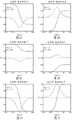
图3A示出了对于K0=1和K∞=-0.5的克劳修-莫索缔(Clausius-Mossotti)因子的实部和虚部。Figure 3A shows the real and imaginary parts of the Clausius-Mossotti factor for
图3B示出了对于K0=-1和K∞=0.5的克劳修-莫索缔因子的实部和虚部。Figure 3B shows the real and imaginary parts of the Clausius-Mossote factor for K0= -1 andK∞ = 0.5.
图3C示出了对于K0=1和K∞=0.5的克劳修-莫索缔因子的实部和虚部。Figure 3C shows the real and imaginary parts of the Clausius-Mossote factor for
图3D示出了对于K0=-1和K∞=-0.5的克劳修-莫索缔因子的实部和虚部。Figure 3D shows the real and imaginary parts of the Clausius-Mossote factor for K0= -1 andK∞ = -0.5.
图3E示出了对于K0=1和K∞=-1的克劳修-莫索缔因子的实部和虚部。Figure 3E shows the real and imaginary parts of the Clausius-Mossote factor for
图3F示出了对于K0=-1和K∞=1的克劳修-莫索缔因子的实部和虚部。Figure 3F shows the real and imaginary parts of the Clausius-Mossote factor for K0= -1 and K[infinity ]=1.
图4示出了修正的史密斯圆图,其使胶体液体和纳米粒子的复介电常数与由谐波激励的频率参数化的复克劳修-莫索缔因子相关。Figure 4 shows a modified Smith chart correlating the complex permittivity of colloidal liquids and nanoparticles with the complex Clausu-Mossole factor parameterized by the frequency of the harmonic excitation.
图5示出了输入平面波,其与单个介电纳米球相互作用以产生衍射散射波和衍射透射衍射波,该衍射透射衍射波通过该球被相移。面积dA的圆环域在屏幕的平面内。长度r的线在该图像中不是按比例的,且应该被认为几乎平行于z轴,使得远场点C远离纳米球的中心。线
图6A示出了基于在微流控控制通道内的折射率匹配液体的平流重定向光的现有技术实施例。Figure 6A shows a prior art embodiment of advective redirection of light based on an index matching liquid within a microfluidic control channel.
图6B示出了作为图6A中的设备的半径的函数的开启和关闭状态折射率。Figure 6B shows on and off state refractive indices as a function of radius for the device in Figure 6A.
图7A示出了基于介电电泳的光束转向的一个实施例,以形成足以使光的路径弯曲直到它被释放用于自由空间传播为止的渐变折射率。Figure 7A illustrates one embodiment of dielectrophoresis-based beam steering to create a graded index of refraction sufficient to bend the light's path until it is released for free space propagation.
图7B示出了作为图7A中的设备的半径的函数的折射率。Figure 7B shows the refractive index as a function of the radius of the device in Figure 7A.
图8A示出了在楔形密封壳的表面上的横截面电极,其中折射率梯度液体受到不均匀电场的影响。楔形物针对正半径符号规约被定向。Figure 8A shows a cross-sectional electrode on the surface of a wedge-shaped sealed enclosure where the refractive index gradient liquid is subjected to a non-uniform electric field. Wedges are oriented for the positive radius sign convention.
图8B示出了在楔形密封壳的表面上的电极,其中折射率梯度液体IGL受到不均匀电场的影响。楔形物针对负半径符号规约被定向。Figure 8B shows electrodes on the surface of a wedge-shaped sealed envelope where the refractive index gradient liquid IGL is subjected to a non-uniform electric field. Wedges are oriented for the negative radius sign convention.
图9示出了对于传播到图的页面内的光束当复克劳修-莫索缔因子的实部大于零时在稳态条件下的电极和折射率梯度液体的横截面。Figure 9 shows the cross-section of the electrode and refractive index gradient liquid under steady state conditions for a beam propagating into a page of the figure when the real part of the complex Crowsius-Mossole factor is greater than zero.
图10示出了对于传播到图的页面内的光束当复克劳修-莫索缔因子的实部大于零时在稳态条件下的电极和折射率梯度液体的横截面。Figure 10 shows the cross-section of the electrode and refractive index gradient liquid under steady state conditions when the real part of the complex Crowsius-Mossole factor is greater than zero for a beam propagating into a page of the figure.
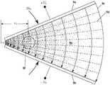
图11示出了基于楔形微流控通道和电极以在圆形设备的一部分上诱导梯度折射率的示例介电电泳光束转向设备的剖视图。示出一般光束轨迹,包括它到自由空间内的释放。11 shows a cross-sectional view of an example dielectrophoretic beam steering device based on wedge-shaped microfluidic channels and electrodes to induce a gradient index of refraction on a portion of a circular device. The general beam trajectory is shown, including its release into free space.
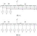
图12在透视图中示出了图11中的用于控制光转向的分段的一组电极,其中电极布置在折射率梯度液体周围。Figure 12 shows a set of electrodes in a perspective view of the segment for controlling light turning of Figure 11, wherein the electrodes are arranged around a gradient index liquid.
图13示出了在来自非平行扁平电极的非均匀电场的影响下的纳米粒子的稳态扩散的潜在解函数的曲线图,所述非平行扁平电极形成对于折射率梯度流体的楔形密封区的边界。解对应于图9-12。Figure 13 shows a graph of a potential solution function for steady-state diffusion of nanoparticles under the influence of a non-uniform electric field from non-parallel flat electrodes forming a wedge-shaped seal for a refractive index gradient fluid boundary. The solution corresponds to Figures 9-12.
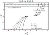
图14示出了针对固体纳米粒子的范围从10%-90%以20%为间隔的不同体积分数vS的归一化纳米粒子折射率相对于归一化半径的曲线图,假设在λο=532nm的波长下归一化半径R=50且纳米球半径b=l00nm。Figure 14 shows a plot of normalized nanoparticle refractive index versus normalized radius for different volume fractionsvS ranging from 10%-90% in 20% intervals for solid nanoparticles, assuming atλo Normalized radius R = 50 and nanosphere radius b = 100 nm at a wavelength of =532 nm.
图15示出了用于增加仰角控制的附加电极的示例,该仰角控制是来自图9的光束转向的已经存在的方位角控制。FIG. 15 shows an example of additional electrodes for adding elevation control, which is an already existing azimuth control from the beam steering of FIG. 9 .
图16A示出了基于介电电泳的圆形的光束转向,以形成梯度折射率介质来限制光和重定向光。Figure 16A illustrates dielectrophoresis based circular beam steering to form a gradient index medium to confine and redirect light.
图16B示出了图16A的梯度折射率分布以及均匀折射率状态。Figure 16B shows the gradient index profile and uniform index state of Figure 16A.
图17示出了微流控控制通道中的纳米粒子的分布的横截面,该微流控控制通道可以提供与由渐变折射率光纤提供的渐变折射率约束类似的光束的渐变折射率约束,除了折射率由介电电泳过程电子地可控制以外。Figure 17 shows a cross-section of the distribution of nanoparticles in a microfluidic control channel that can provide graded-index confinement of a beam similar to that provided by graded-index fibers, except The refractive index is electronically controllable by the dielectrophoretic process.
图18A示出了基于介电电泳的电子地可控制的透镜的横截面。Figure 18A shows a cross section of an electronically controllable lens based on dielectrophoresis.
图18B示出了当复值的克劳修-莫索缔因子的实部大于零时作为会聚透镜的透镜半径的函数的折射率。Figure 18B shows the refractive index as a function of the lens radius of the converging lens when the real part of the complex-valued Clausius-Mossault factor is greater than zero.
图18C示出了当复值的克劳修-莫索缔因子的实部大于零时作为发散透镜的透镜半径的函数的折射率。Figure 18C shows the refractive index as a function of the lens radius of a diverging lens when the real part of the complex-valued Clausius-Mossote factor is greater than zero.
图19示出了环形电极的透视图,该环形电极用于针对介电电泳过程提供不均匀电场以在电子透镜中可变地聚焦光。Figure 19 shows a perspective view of a ring electrode used to provide a non-uniform electric field for a dielectrophoretic process to variably focus light in an electron lens.
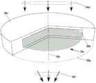
图20示出了集成环形电极和密封壳的透视剖视图,该密封壳在利用纳米粒子的浓度的基于介电电泳的透镜的形成中被使用。Figure 20 shows a perspective cross-sectional view of an integrated ring electrode and a sealed can used in the formation of a dielectrophoresis-based lens utilizing the concentration of nanoparticles.
图21A示出了有效地提供同相和正交电场激励和行进电压波的多相电压激励。Figure 21A shows a polyphase voltage excitation that effectively provides in-phase and quadrature electric field excitation and traveling voltage waves.
图21B示出了具有任意同相和正交电场激励的多相和振幅电压激励。Figure 21B shows polyphase and amplitude voltage excitations with arbitrary in-phase and quadrature electric field excitations.
图22A示出了当存在同相和正交场分量时在电极上方的行波电场的实部。Figure 22A shows the real part of the traveling wave electric field over the electrodes when in-phase and quadrature field components are present.
图22B示出了当存在同相和正交场分量时在电极上方的行波电场的虚部。Figure 22B shows the imaginary part of the traveling wave electric field over the electrodes when in-phase and quadrature field components are present.
图23示出了相对于电极的示例振幅变化及其导数。Figure 23 shows example amplitude changes with respect to electrodes and their derivatives.
图24A示出了当存在同相和正交场分量以及沿着电极的振幅反转时在电极上方的行波电场的实部。Figure 24A shows the real part of the traveling wave electric field over the electrode when there are in-phase and quadrature field components and amplitude reversal along the electrode.
图24B示出了当存在同相和正交场分量以及沿着电极的振幅反转时在电极上方的行波电场的虚部。Figure 24B shows the imaginary part of the traveling wave electric field over the electrode when there are in-phase and quadrature field components and amplitude reversal along the electrode.
图25在透视图中示出了光束转向系统,其可以通过使用分立的电极阵列来将光重定向到方位角的2π弧度内和在仰角的±π/4弧度上。Figure 25 shows, in perspective view, a beam steering system that can redirect light to within 2π radians of azimuth and ±π/4 radians of elevation using discrete electrode arrays.
图26示出了基于介电电泳的透镜的透视和剖视图,该透镜在电极的圆形和同心阵列上利用行进电压波。Figure 26 shows perspective and cross-sectional views of a dielectrophoresis-based lens utilizing traveling voltage waves on a circular and concentric array of electrodes.
图27A示出了在球面谐波函数的形式中的基本非结构化角模的示例。Figure 27A shows an example of a fundamental unstructured angular mode in the form of a spherical harmonic function.
图27B示出了在艾里(Airy)函数的形式中的基本非结构化径向模式的示例,其中该模式仅在微流控控制体积中示出。Figure 27B shows an example of a substantially unstructured radial mode in the form of an Airy function, where the mode is only shown in a microfluidic control volume.
图28示出了在非测地线轨迹上的对称轴周围传播的基本非结构化模式,所述非测地线轨迹正好在微流控控制体积的区域中的内部固体介电球上方形成。Figure 28 shows a substantially unstructured pattern propagating around an axis of symmetry on a non-geodetic trajectory formed just above an inner solid dielectric sphere in the region of the microfluidic control volume.
图29A示出了在
图29B示出了在艾里函数的形式中的结构化有限功率径向模式,其中该模式仅被包含在微流控控制体积中。Figure 29B shows the structured finite power radial mode in the form of the Airy function, where the mode is contained only in the microfluidic control volume.
图30示出了在被限制到恒定纬度的非测地线轨迹上的光束的主波瓣的示例结构化角轨迹和强度。Figure 30 shows an example structured angular trajectory and intensity of the main lobe of a beam on a non-geodesic trajectory constrained to constant latitude.
图31示出了在未被限制到简单的恒定纬度的非测地线轨迹上的光束的主波瓣的示例结构化角轨迹和强度。Figure 31 shows an example structured angular trajectory and intensity of the main lobe of a beam on a non-geodesic trajectory not constrained to a simple constant latitude.
实施例的理论和描述Theory and Description of Embodiments
以下篇幅提供了对于光电子的光转向和光聚焦的DBS的基本理论和实施例的相当多的细节。该理论被提供,使得不存在关于在复杂的技术领域中讨论的东西确切地是什么的问题。详细的技术讨论还允许对现有技术的局限性的见识,并最终允许不太熟悉材料的那些人使用一个一致且统一的标记法来更容易地获取当前材料。这种材料本质上在性质上是多学科的并从许多不同的领域得到,这些领域包括但不限于:流体流动、热传递、连续介质力学、电磁学、电子学、化学、材料科学、光学、热力学和数学。The following sections provide considerable detail on the basic theory and embodiments of DBS for photo-turning and light-focusing of optoelectronics. The theory is provided such that there is no question of exactly what is being discussed in a complex technical field. Detailed technical discussions also allow insight into the limitations of prior art and ultimately allow easier access to current materials using a consistent and uniform notation for those less familiar with the material. This material is multidisciplinary in nature and derived from many different fields including, but not limited to: fluid flow, heat transfer, continuum mechanics, electromagnetism, electronics, chemistry, materials science, optics, Thermodynamics and Mathematics.
对于DEP过程的二元微积分Binary Calculus for DEP Processes
考虑空间A和时间B的三维向量函数,其是任意的且不一定是来自麦克斯韦方程中的场量。这些三维向量的并向量积被表示为AB,并具有可以被写为具有元素aij=AiBj的矩阵的九个分量,并使用爱因斯坦求和约定被正式给出为Consider a three-dimensional vector function in space A and time B, which is arbitrary and not necessarily a field quantity from Maxwell's equations. The union-vector product of these three-dimensional vectors is denoted AB and has nine components that can be written as a matrix with elements aij = Ai Bj , and is formally given using the Einstein summation convention as

其中,双下标指示在三个空间维度上的总和,且通常AB≠BA。在这里不区分开协变向量和逆变向量。在下面的分析中,所有推导都使用笛卡儿并向量(cartesian dyadics)被提供,然而因而得到的方程在任何自相容的坐标系中都是正确的。where double subscripts indicate the sum in three spatial dimensions, and usually AB≠BA. No distinction is made between covariant and contravariant vectors here. In the following analysis, all derivations are provided using Cartesian dyadics, however the resulting equations are correct in any self-consistent coordinate system.
我们将使用列维-奇维塔(Levi-Civita)张量∈ijk以使旋度和其他运算易于计算。特别是,列维-奇维塔张量取值We will use Levi-Civita tensors ∈ijk to make curl and other operations easy to compute. In particular, the Levi-Civita tensor takes the value

且我们可以通过直接计算来表明:And we can show by direct calculation:
∈ijk∈klm=∈kij∈klm=δilδjm-δimδjl (3)∈ijk ∈klm = ∈kij ∈klm =δil δjm -δim δjl (3)
其中,δij是Kronecker Delta函数。列维-奇维塔张量用来将A和B的叉积写为:where δij is the Kronecker Delta function. The Levi-Civita tensor is used to write the cross product of A and B as:

并将A的旋度写为:and write the curl of A as:

其中,我们照常应用爱因斯坦求和约定。Among them, we apply the Einstein summation convention as usual.
重要的第一个结果是并向矢积的散度。它可以如下被展开The important first result is the divergence of the vector product. It can be expanded as follows


其中,在将来我们可能并不总是在中间结果中写出明显的单位因子如

接下来,得到了向量的旋度的叉积。它可以展开为Next, the cross product of the curl of the vector is obtained. It can be expanded to

类似地,它的补充是Similarly, its complement is

此外,also,


使得make


上述方程的一个特殊情况对准静电(QES)系统的分析是有用的,以及DEP特别地规定了无旋场,使得

其中,通过观察对于任意标量U=A2/2我们可以使用3×3单位矩阵I写方程来获得在上述方程中的最后一个等式。特别是,Here, the last equation in the above equation can be obtained by observing that for any scalar U=A2 /2 we can write the equation using the 3×3 identity matrix I. in particular,

使得make
当U是标量时,
接下来,通过使用方程9和它的补充(其通过用B交换A而形成,反之亦然),我们可以单独地对


且现在将这些方程代回到方程17中,使得and now substituting these equations back into

对于QES系统的一个特殊情况是,其中A和B是无旋的,使得


通过在上述方程中设置A=B,我们得到By setting A=B in the above equation, we get

其中,A2=A·A。现在将方程18用在方程25中,我们得到where A2 =A·A. Now using

使得make
当A仅仅是无旋的时,

我们将方程18和28总结为We summarize
当A仅仅是无旋的时,
当A是无旋的和螺线管形的时,
所需要的下一个关系通过使用方程2和3导出,使得有序差的散度是The next relation required is derived by using


该结果可以与方程9组合,使得This result can be combined with Equation 9 such that

其在当A和B是螺线管形的特殊情况下,即,
当A和B是螺线管形的时,
麦克斯韦方程和标记法Maxwell's equations and notation
我们以对于在SI单位中的宏观系统的麦克斯韦方程的时空版本和对于均质、各向同性和线性材料的本构关系开始。特别是,在SI单位中的麦克斯韦方程是We start with the spatiotemporal versions of Maxwell's equations for macroscopic systems in SI units and the constitutive relations for homogeneous, isotropic and linear materials. In particular, Maxwell's equations in SI units are


并且本构关系是and the constitutive relation is


上述电磁量包括电场强度ε、电场密度


ε(r,t)→E(r)eiωt (43)ε(r, t)→E(r)eiωt (43)


ρf(r,t)→ρf(r)eiωt (46)ρf (r, t)→ρf (r)eiωt (46)
σ(r,t)→σ(r,ω) (47)σ(r, t) → σ(r, ω) (47)
∈(r,t)→∈(r,ω) (48)∈(r, t) → ∈(r, ω) (48)
μ(r,t)→μ(r,ω), (49)μ(r, t) → μ(r, ω), (49)
其中,除非另有说明,否则量如E(r)通常是复值量,并且
无论发生哪种情况,我们都可以将麦克斯韦方程改写为In either case, we can rewrite Maxwell's equations as


其中,上面的第三和第四个方程根据取第一和第二个方程的散度并使用向量恒等式


提供上述方程以建立在接下来的DEP分析中使用的标记法和符号规约。The above equations are provided to establish the notation and notation convention used in the following DEP analysis.
时间平均的麦克斯韦应力张量time-averaged Maxwell stress tensor
除了麦克斯韦方程35-38和本构方程39-41以外,还有洛伦兹力方程,其对于单个电荷由下式给出In addition to Maxwell's equations 35-38 and constitutive equations 39-41, there is also the Lorentz force equation, which for a single charge is given by

其中,q是电荷,以及v是在惯性参照系中的电荷的速度向量。如果我们将两侧都乘以N,N是以每单位体积的电荷数为单位的带电粒子的浓度。注意,N不同于每单位体积的纳米粒子的浓度u。因此,于是我们可以将ρf=Nq确定为自由电荷密度,以及将


另外,因为光速平方是c2=1/(∈μ),所以坡印亭向量除以在介质中的光速平方是In addition, since the speed of light squared is c2 =1/(∈μ), the Poynting vector divided by the speed of light squared in the medium is

因此,therefore,

通过插入麦克斯韦方程35-38到体积力方程61内来组合结果,以及进一步利用方程62,我们得到Combining the results by inserting Maxwell's equations 35-38 into the body force equation 61, and further using equation 62, we get

以及在重新排列项并使用

因此,最初聚焦于项-1,我们找到Therefore, focusing initially on term -1, we find

其中,在最后一行中的第一项是减去电场能量密度的梯度,以及第二项是场量的并向量积的散度。where the first term in the last row is the gradient minus the electric field energy density, and the second term is the divergence of the union-vector product of the field quantities.
类似地,对于T2,我们可以让

因此,包括场致机械应力矩阵元素的麦克斯韦应力张量是:Therefore, the Maxwell stress tensor including elements of the field-induced mechanical stress matrix is:

每单位体积的力被给出为The force per unit volume is given as

其具有由于辐射压力而引起的第一项和由于场致应力而引起的第二项。It has a first term due to radiation pressure and a second term due to field induced stress.
对于准静电DEP系统,麦克斯韦应力张量需要针对时间平均体积力被评估,因此,如果我们假设具有相移的谐波电场和磁场,那么我们可以将空间和时间分开。例如,对于电场,我们可以写For quasi-electrostatic DEP systems, the Maxwell stress tensor needs to be evaluated for the time-averaged body force, so if we assume harmonic electric and magnetic fields with phase shifts, then we can separate space and time. For example, for the electric field, we can write


其中,φ∈=φ∈(r),E(r)和D(r)是位置r的实值函数。然后于是我们可以将时间平均麦克斯韦应力张量写为where φ∈ = φ∈ (r), E(r) and D(r) are real-valued functions of position r. Then we can then write the time-averaged Maxwell stress tensor as

让我们假设电极被引入使得电场强度具有同相和正交分量,使得通过设计Let us assume that the electrodes are introduced such that the electric field strength has in-phase and quadrature components such that by design
ε=ERcos(ωt)+EIsin(ωt) (73)ε=ER cos(ωt)+EI sin(ωt) (73)

其中,ER不平行于EI,并且相移φ∈归因于材料性质。然后我们考虑并向量积:whereER is not parallel toEI and the phase shift φ∈ is due to material properties. Then we consider the union-vector product:

时间平均值可以通过首先使用对于任意角度a和b的三角恒等式来获得The time average can be obtained by first using the trigonometric identities for arbitrary angles a and b
2cos a cos b=cos(a+b)+cos(a-b) (76)2cos a cos b=cos(a+b)+cos(a-b) (76)
2cos a sin b=sin(a+b)-sin(a-b) (77)2cos a sin b=sin(a+b)-sin(a-b) (77)
2sin a cos b=sin(a+b)+sin(a-b) (78)2sin a cos b=sin(a+b)+sin(a-b) (78)
2sin a sin b=-cos(a+b)+cos(a-b) (79)2sin a sin b=-cos(a+b)+cos(a-b) (79)
使得

并将此方法应用于方程75中的每个项,我们得到时间平均并向量积为and applying this method to each term in Equation 75, we obtain the time-averaged sum-vector product as

其中,星号指示复共轭,以及Re[]是实部运算符。此外注意复介电常数是:where the asterisk indicates complex conjugation, and Re[] is the real operator. Also note that the complex permittivity is:

此外,我们还发现对于内积使用相同的过程,时间平均是Furthermore, we also find that using the same process for the inner product, the time average is

因此,时间平均麦克斯韦应力张量是Therefore, the time-averaged Maxwell stress tensor is

然而,平均有质动力的电分量是However, the electric component of the average plasmonic force is

以及我们立即看到简化对于


以及对于准静电学在无旋场

所以,准静电力(即,开尔文力)密度从方程84被得到为:Therefore, the quasi-electrostatic force (ie, Kelvin force) density is obtained from Equation 84 as:

这是应用于半径为b且体积如下的球形纳米粒子的开尔文力密度This is the Kelvin force density applied to spherical nanoparticles of radius b and volume

与方程88相关联的
我们试图找到针对在区域Ω2中的局部场的表达式,使得我们可以找到针对极化度αS的方程,该方程使在液体中的电场强度EL与介电球的极化相关。我们通过将在区域Ω2中的总局部电场考虑为在液体中的电场强度加上由于束缚体积极化而引起的场和来自在表面w2上的束缚表面极化的场之和来开始。这导致在宏观有效场(EL和Eloc)和极化场(


其中,EL取决于施加到电极的电压,

p=αSEloc。 (91)p=αSEloc . (91)
这可能与平均偶极矩的电势有关。正如我们将看到的,这然后提供有效介电常数,这是我们的计算的目标。This may be related to the potential of the average dipole moment. As we will see, this then provides the effective dielectric constant, which is the target of our calculations.
为了找到洛伦兹关系式的三个场分量,我们需要首先找到系统中的各种电荷。通常,因为宏观极化的散度是体积电荷密度

P=D-∈0E, (92)P=D-∈0 E, (92)
以及每单位面积的束缚表面电荷密度为and the bound surface charge density per unit area is

此外,通过在体积上对

其中,
对于边界w1,自由电荷密度、束缚电荷密度和总电荷密度为For boundary w1 , the free charge density, bound charge density and total charge density are


σt1=σf1+σb1=∈0EL. (97)σt1 =σf1 +σb1 = ∈0 EL . (97)
其中,复相对介电常数


σt3=σf3+σb3=-∈0EL, (100)σt3 =σf3 +σb3 =-∈0 EL , (100)
这表明在电极上的总表面电荷密度(即,σt1和σt3)相等且符号相反。它还表明在电介质内的总电场强度的一个分量是EL。然而,由于在球体上诱导的束缚电荷,这并不是唯一的分量。因此,由于球体,总局部场必须是EL加上电场分量。This indicates that the total surface charge densities on the electrodes (ie, σt1 and σt3 ) are equal and opposite in sign. It also shows that one component of the total electric field strength within the dielectric isEL . However, this is not the only component due to the bound charges induced on the sphere. Therefore, due to the sphere, the total local field must beEL plus the electric field component.
特别是,对于球形边界ω2,电荷密度为In particular, for the spherical boundary ω2 , the charge density is


我们可以使用在表面ω2上的净电荷分布σt2以通过从在球面上的源到在球体的中心处的观察点(即,在

因为我们采用总和来确保我们具有在半径b的球体的中心处的总电场,所以我们可以识别出Because we take the sum to ensure that we have the total electric field at the center of the sphere of radius b, we can identify

使得make

使得在液体中,我们最终可以相对于液体的局部背景介质写出such that in a liquid we can finally write with respect to the local background medium of the liquid

接下来,我们考虑在纳米粒子内的束缚极化电荷。我们将假设原子在立方网格上,这只是一个通常可以被放宽的方便假设。也就是说,对于其他几何形状,包括无定形介质(如玻璃),结果是大致正确的,但是在这些其他情况下计算可能变得非常复杂。特别是,通过对在位置rj处的源电荷qj求和来给出总电场强度Next, we consider bound polarized charges within nanoparticles. We will assume that the atoms are on a cubic grid, which is just a convenient assumption that can usually be relaxed. That said, for other geometries, including amorphous media (such as glass), the results are roughly correct, but calculations can become very complicated in these other cases. In particular, the total electric field strength is given by summing the source charges qj at positions rj

其中,p=qd,以及d是电荷在z轴方向上的位移。设置


但对于立方晶格,我们对于


因此,对于立方晶格且作为对于许多其他实际材料的很好的近似,我们有Therefore, for a cubic lattice and as a good approximation for many other practical materials, we have

从上面的计算中,我们发现洛伦兹关系式可以在球形纳米粒子被移除以及电场与液体相关的情况下针对局部电场强度被评估。结果是From the above calculations, we find that the Lorentz relation can be evaluated for the local electric field strength with the spherical nanoparticles removed and the electric field associated with the liquid. turn out

因此,在每单位体积的粒子的浓度u和极化率αS的情况下,则使用方程109和114Therefore, in the case of the concentration u and the polarizability αS of the particles per unit volume, then equations 109 and 114 are used

使得make

存在具有

具有每单位体积的浓度u的纳米粒子的集合的有效极化密度于是为The effective polarization density of a collection of nanoparticles with concentration u per unit volume is then

以及as well as

注意,
注意,上述推导仅仅是示例性的,并且额外的层可以被添加到介电纳米粒子以提供与多层球形几何形状一致的复介电常数的其他函数。Note that the above derivation is merely exemplary, and additional layers may be added to the dielectric nanoparticles to provide other functions of complex permittivity consistent with the multi-layer spherical geometry.
例如,为了确保稳定的胶体,可以添加表面活性剂作为对纳米粒子的外层的涂层。这将要求在内电介质和外涂层之间的边界处的另一层总束缚电荷需要被包括在分析中,并且对于
此外,注意从方程56中且为了方便起见假设介电常数的虚部等于零,我们有Furthermore, noting that from Equation 56 and assuming for convenience that the imaginary part of the permittivity is equal to zero, we have


使得make

其是对于嵌在介电液体中的固体球的复克劳修-莫索缔(CM)因子。此外,经过某个代数后,我们可以隔离CM因子的实部和虚部,使得It is the complex Clausius-Mossolene (CM) factor for solid spheres embedded in a dielectric liquid. Furthermore, after some algebra, we can isolate the real and imaginary parts of the CM factors such that


其中in


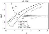
注意,KR和KI可以同时采取正值和负值。正如我们将看到的,这允许在纳米粒子上的力和漂移速度根据在电极上的电压的谐波激励的频率ω而采取正值或负值。在∈S>∈L的情况下,我们有K∞>0。因此,为了使K0<0,我们将选择液体,其可以是几种化学物质的混合物,以具有σL>σS。这将简单地通过改变在电极上的频率和电压振幅如对特定应用所需的提供使用DEPS光学器件来使光聚焦、散焦和准直的手段,如稍后在特定实施例中所展示的。图3A-F示出对于K0和K∞的特定值的CM因子的实部和虚部相对于频率的对数线性曲线图。Note that KR and KI can take both positive and negative values. As we will see, this allows the force on the nanoparticle and the drift velocity to take positive or negative values depending on the frequency ω of the harmonic excitation of the voltage on the electrodes. In the case of ∈S > ∈L , we have K∞ > 0. Therefore, in order to have K0 <0, we will choose a liquid, which can be a mixture of several chemicals, to have σL >σS . This will provide a means of focusing, defocusing and collimating light using DEPS optics simply by varying the frequency and voltage amplitude across the electrodes as required for a particular application, as demonstrated later in specific examples . 3A-F show log-linear plots of the real and imaginary parts of the CM factor versus frequency for particular values ofK0 and K∞.
方程122是在复平面上的修正的双线性变换。取

在设置z=zR+izI和K=KR+iKI时,我们可以用某个代数从因而得到的方程的实部和虚部中获得一组参数方程When setting z = zR + izI and K = KR + iKI , we can use some algebra to obtain a set of parametric equations from the real and imaginary parts of the resulting equations


其是形成使液体和纳米球的介电常数与CM因子有关的修正的史密斯圆图的正交圆。事实证明,纳米粒子的力和漂移速度与CM因子成比例,如我们将看到的。因此,图4所示的修正的史密斯圆图有助于在力(或漂移速度)和材料参数之间转换。It is an orthogonal circle that forms a modified Smith chart relating the dielectric constants of the liquid and nanospheres to the CM factor. It turns out that the force and drift velocity of nanoparticles are proportional to the CM factor, as we will see. Therefore, the modified Smith chart shown in Figure 4 helps to convert between force (or drift velocity) and material parameters.
图4中的史密斯圆图示出了由驱动电极的谐波激励频率ω参数化的许多轨迹。轨迹对应于图3A-F。例如,由从史密斯圆图点4a到史密斯圆图点4b的半圆形成的轨迹对应于图3D。由从史密斯圆图点4a到史密斯圆图点4d的半圆形成的轨迹对应于图3B,并且显示了对于复CM因子的实部的正值和负值。史密斯圆图点4a、4b、4d和4e中的每一个对应于K0或K∞。当史密斯圆图轨迹包括史密斯圆图原点4c时,那么将有正值和负值都作为CM等式的实部,CM等式通过在切换在电极上的激发频率来在纳米粒子上提供吸引力和排斥力。此外,在每个半圆形轨迹的顶部处有零力点,例如在零力点4f处,在那里没有在纳米粒子上的DEP力。The Smith chart in Figure 4 shows a number of trajectories parameterized by the harmonic excitation frequency ω of the driving electrode. The traces correspond to Figures 3A-F. For example, the locus formed by the semicircle from
时间平均DEP力time-averaged DEP force
遭受基于DEP的有质动力的纳米粒子也将感觉到它的粘性流体环境的影响。特别是,在稳态条件下的牛顿第二定律变成A plasmodynamic nanoparticle subject to DEP will also feel the effects of its viscous fluid environment. In particular, Newton's second law under steady state conditions becomes

其中,在流体中对于球形粒子阻力的众所周知的斯托克斯定律用于发展第二项,以及η是围绕纳米粒子的流体的动态粘度。显然,平均力与稳态漂移速度之比由固有迁移率因子给出:where the well-known Stokes' law for spherical particle resistance in a fluid is used to develop the second term, and η is the dynamic viscosity of the fluid surrounding the nanoparticle. Obviously, the ratio of the average force to the steady state drift velocity is given by the intrinsic mobility factor:

穿过流体的纳米粒子的DEP漂移速度通过下式从方程88获得:The DEP drift velocity of the nanoparticles passing through the fluid is obtained from Equation 88 by:

因此,总之Therefore, in short

其中,我们将相对流动性因子定义为where we define the relative liquidity factor as


显然,可以从保守势能U(即,应力张量)方面来写出平均力,使得在平衡条件下(即不是时间的函数)穿过液体的粒子的净通量由漂移电流给出:Clearly, the average force can be written in terms of the conservative potential U (ie, the stress tensor) such that the net flux of particles through the liquid under equilibrium conditions (ie, not a function of time) is given by the drift current:

其中,u(r)是每单位体积的粒子浓度[每单位体积的粒子数],并且由于热搅动布朗运动而引起的粒子的扩散由下式给出:where u(r) is the particle concentration per unit volume [number of particles per unit volume], and the diffusion of particles due to thermally agitated Brownian motion is given by:

其中,u(r)=Iu(r),以及u是粒子浓度,即每单位体积的粒子数,以及D是我们的分析的待确定的扩散系数。在平衡条件下,粒子的净向量通量为零,使得j漂移(r)+j扩散(r)=0。因此,where u(r)=Iu(r), and u is the particle concentration, ie the number of particles per unit volume, and D is the diffusion coefficient to be determined for our analysis. Under equilibrium conditions, the net vector flux of particles is zero, such thatjdrift (r)+jdiffusion (r)=0. therefore,

观察到根据梯度的定义,如果W是能量,那么


以及as well as

以及as well as

或者在引入附加项时,该附加项具有为零的l的内积,我们发现Or when introducing an additional term, which has an inner product of zero l, we find

其中,在右边的第二项将能级设置为任意值,而第三项具有下面的性质:外积(GH-HG)的换位元总是反对称矩阵,其中

其中,例如我们可采用Among them, for example, we can use

其中,函数g和h仅是坐标x和y的实值函数。此外注意,ER和EL实际上并不仅限于xy平面。例如在圆柱坐标中,我们可以采用在每个极方位角处的单位圆柱体的切平面作为其中电场强度的同相和正交分量被定义的平面。这将对来自任意形成的外壳的光束转向有重要后果,例如,飞机的外壳对于适当的空气动力特性具有复杂的形状。where the functions g and h are only real-valued functions of the coordinates x and y. Also note thatER andEL are not really limited to the xy plane. In cylindrical coordinates, for example, we can take the tangent plane of the unit cylinder at each polar azimuth as the plane in which the in-phase and quadrature components of the electric field strength are defined. This will have important consequences for beam steering from arbitrarily formed hulls, eg aircraft hulls with complex shapes for proper aerodynamic properties.
因此,我们可以写出方程Therefore, we can write the equation

以及as well as

然而在统计力学中,麦克斯韦玻尔兹曼统计用来描述在热平衡中在被允许的能量状态上的非相互作用的材料粒子的平均分布。当温度足够高或者粒子密度足够低以使量子效应变得可忽略时,这个分布是可适用的。使用这个论断,我们写出In statistical mechanics, however, Maxwell-Boltzmann statistics are used to describe the average distribution of non-interacting material particles in thermal equilibrium over the allowed energy states. This distribution is applicable when the temperature is high enough or the particle density is low enough that quantum effects become negligible. Using this assertion, we write

其中,A是与在单位体积中的粒子的总数相关的常数,并且kB是玻尔兹曼常数。因此,whereA is a constant related to the total number of particles in a unit volume, and kB is the Boltzmann constant. therefore,

因此,therefore,

以及as well as

因此therefore
D=γkBT, (153)D = γkB T, (153)
其对于麦克斯韦应力张量具有非零非对角元素的情况下是众所周知的爱因斯坦扩散系数的扩展。It is an extension of the well-known Einstein diffusion coefficient for the case where the Maxwell stress tensor has non-zero off-diagonal elements.
与DEP相关联的时间平均力的准静电近似假设电场强度E的振幅在空间中是不变的。这可以被放宽,如果与谐波激励τ=2π/ω的周期相比时间变化是慢的。因此,如果t>>τ,那么近似地,E=E(r,t)=ER(r,t)+iEI(r,t),使得DEP粒子通量为The quasi-electrostatic approximation of the time-averaged force associated with DEP assumes that the amplitude of the electric field strength E is invariant in space. This can be relaxed if the time variation is slow compared to the period of the harmonic excitation τ=2π/ω. Therefore, if t>>τ, then approximately, E=E(r ,t)=ER(r,t)+iEI (r,t), such that the DEP particle flux is

作为比较,对于扩散过程,粒子通量是As a comparison, for the diffusion process, the particle flux is

对于平流For advection
jadv(r,t)=u(r)v(r) (156)jadv (r,t)=u(r)v(r) (156)
以及对于正/负带电粒子的电泳(EP)and electrophoresis (EP) for positively/negatively charged particles
jep(r,t)=±u(r,t)μ(r,t)E。 (157)jep (r,t)=±u(r,t)μ(r,t)E. (157)
总粒子通量于是为The total particle flux is then

以及通过连续性,我们可以写出and by continuity, we can write

其中,Q(r,t)是以每单位体积的粒子为单位的体积源。where Q(r,t) is the volume source in particles per unit volume.
对于只有DEP和扩散是主要现象的特殊情况,即当在纳米粒子上使用表面活性剂涂层以在重力场中保持稳定和分离的胶体时,重力被忽略。然后我们得到总粒子通量For the special case where only DEP and diffusion are the dominant phenomena, that is, when a surfactant coating is used on nanoparticles to maintain stable and separated colloids in a gravitational field, gravity is neglected. Then we get the total particle flux

因此,当体积源为零Q(r,t)=0时,那么Therefore, when the volume source is zero Q(r, t) = 0, then

以及假设目前γ1、γ1和γ是常数(这是我们可以如所需的稍后可放宽的假设),且不是空间的函数。因此,写u=u(r,t),并使用扩散系数的定义,我们得到对于纳米粒子空间分布的主方程As well as the assumption that γ1 , γ1 and γ are currently constant (this is an assumption we can later relax as desired) and not a function of space. Therefore, writing u = u(r, t), and using the definition of diffusion coefficient, we obtain the master equation for the spatial distribution of nanoparticles

基于DEP的纳米粒子浓度的综述A review of DEP-based nanoparticle concentrations
下面的方程假设只有DEP和扩散过程在起作用,其中谐波电压激励被提供给在液体中的固体纳米粒子的胶体悬浮液附近的电极,液体和悬浮液都是光学透明的,但通常没有作为波长的函数的相同折射率。特别是,The equations below assume that only DEP and diffusion processes are at work, where harmonic voltage excitation is provided to electrodes near a colloidal suspension of solid nanoparticles in a liquid, both optically transparent, but generally not as the same refractive index as a function of wavelength. in particular,

u(r,t)=液态胶体悬浮液中的纳米粒子浓度[#L-3]u(r, t) = nanoparticle concentration in liquid colloidal suspension [#L-3 ]
E(r,t)=复电场强度的振幅[LMT-3I-1]E(r, t) = amplitude of complex electric field strength [LMT-3 I-1 ]
ER(r,t)=复电场强度的振幅的实部[LMT-3I-1]ER (r, t) = real part of the amplitude of the complex electric field strength [LMT-3 I-1 ]
EI(r,t)=复电场强度振幅的虚部[LMT-3I-1]EI (r, t) = imaginary part of complex electric field strength amplitude [LMT-3 I-1 ]
r=位置向量[L]r = position vector [L]
t=当t>>(2π/ω)以允许准静电近似时的时间[T]t = time [T] when t>>(2π/ω) to allow quasi-electrostatic approximation
ω=电极的谐波激励的弧度频率[T-1]ω = radian frequency of the harmonic excitation of the electrode [T-1 ]

η=动态粘度[L-1MT-1]η = dynamic viscosity [L-1 MT-1 ]
b=球形纳米粒子半径[L]b = spherical nanoparticle radius [L]

Υ1=在非旋转场中的相对迁移率[M-1T4I2]Y1 = relative mobility in a non-rotating field [M−1 T4 I2 ]
=πb3KR∈L=πb3 KR∈L
Υ2=在旋转场中的相对迁移率[M-1T4I2]Υ2 = relative mobility in a rotating field [M-1 T4 I2 ]
=2πb3KI∈L=2πb3 KI∈L


∈S=固体纳米粒子的介电常数[L-3M-1T4I2]∈S = dielectric constant of solid nanoparticle [L-3 M-1 T4 I2 ]
=∈o∈s= ∈o ∈s
∈L=液体介质的介电常数[L-3M-1T4I2]∈L = dielectric constant of liquid medium [L-3 M-1 T4 I2 ]
=∈o∈l= ∈o ∈l
∈s=固体纳米粒子的相对介电常数[无单位]∈s = relative permittivity of the solid nanoparticle [unitless]
∈l=液体介质的相对介电常数[无单位]∈l = relative permittivity of the liquid medium [unitless]
∈o=自由空间的介电常数[L-3M-1T4I2]∈o = permittivity of free space [L-3 M-1 T4 I2 ]
=8.85418782×10⁻¹²m-3kg-1s4A2=8.85418782×10⁻¹² m-3 kg-1 s4 A2
σS=固体纳米粒子的电导率[M-1L-3T3I2]σS = Conductivity of solid nanoparticles [M-1 L-3 T3 I2 ]
σL=液体介质的电导率[M-1L-3T3I2]σL = conductivity of liquid medium [M-1 L-3 T3 I2 ]
D=爱因斯坦扩散系数[L2T-1]D = Einstein diffusion coefficient [L2 T-1 ]
=γkBT=γkB T
T=绝对温度[θ]T = absolute temperature [θ]
kB=波尔兹曼常数[L2MT-2θ-1]kB = Boltzmann constant [L2 MT-2 θ-1 ]
=1.38064852×10⁻²³m2kg s-2K-1=1.38064852×10⁻²³ m2 kg s-2 K-1
体积平均折射率volume average refractive index
本章的目的是展示DEP可用于创建允许光束转向的折射率梯度。特别是,包括透明液体主介质中的透明亚波长标度粒子的胶体提供体积平均折射率。通过改变胶体中的纳米粒子的局部体积分数,点对点折射率可以及时动态地改变。The purpose of this chapter is to show that DEP can be used to create refractive index gradients that allow beam steering. In particular, colloids comprising transparent subwavelength-scaled particles in a transparent liquid host medium provide a volume average refractive index. By changing the local volume fraction of nanoparticles in the colloid, the point-to-point refractive index can be dynamically changed in time.
如果我们假设散射过程对平均折射率没有影响,那么对于胶体的液体组分体积分数vL和固体组分的体积分数vS必须合计为1,使得If we assume that the scattering process has no effect on the average refractive index, then the volume fractionvL of the liquid component for the colloid and the volume fractionvS of the solid component must add up to 1, such that
vL+vS=1, (164)vL +vS =1, (164)
以及我们可以推导出平均折射率的关系式。这基于我们对折射率取平均过程如何工作的直觉,并提供下式的平均实际折射率and we can derive the relationship for the average refractive index. This is based on our intuition about how the refractive index averaging process works and provides the average actual refractive index of
nA=nLvL+nSvSnA =nL vL +nS vS
=nL(1-vS)+nSvS=nL (1-vS )+nS vS
=nL+(nS-nL)vS。 (165)=nL +(nS -nL )vS . (165)
固体纳米粒子的体积分数vS没有单位,并且是在0和1之间的纯实数,使得vS通过将粒子浓度乘以每纳米粒子的体积而获得,使得The volume fraction v of solidnanoparticles has no units and is a purely real number between 0 and 1 such that v isobtained by multiplying the particle concentration by the volume per nanoparticle such that

由此,可能将在纳米粒子浓度u和平均折射率之间的直接线性关系提供为Thus, it is possible to provide a direct linear relationship between the nanoparticle concentration u and the average refractive index as

这是在我们在前面章节中发现的纳米粒子浓度和胶体悬浮液的平均折射率之间的直接线性关系。This is a direct linear relationship between the nanoparticle concentration and the average refractive index of the colloidal suspension that we found in the previous section.
严格地说,只有当粒子的半径接近零时,即当b→0且散射过程基本上为零时,方程167才是正确的。当粒子尺寸接近零时,用于改变纳米粒子的空间分布所需的电压转为无穷大。因此,我们被给予动机以得到在nL和nS之间的更实际的平均化方程,使得电压在工程设备的实际范围内。Strictly speaking, equation 167 is only true when the radius of the particle is close to zero, i.e. when b→0 and the scattering process is essentially zero. As the particle size approaches zero, the voltage required to alter the spatial distribution of nanoparticles turns to infinity. Therefore, we are motivated to obtain a more realistic averaging equation betweennL andnS so that the voltage is within the practical range of the engineering device.
此外注意,当粒子尺寸比光的自由空间波长小得多(一般b≤λ0/20)时,则当光束穿过包括分散的纳米粒子的胶体时我们有瑞利散射。当粒子尺寸增加时,则我们通常对于具有与光的波长可比较的尺寸的纳米粒子将使用全米氏散射理论来描述散射过程。Also note that when the particle size is much smaller than the free space wavelength of light (generallyb≤λ0 /20), then we have Rayleigh scattering when the beam passes through a colloid comprising dispersed nanoparticles. As the particle size increases, then we will generally use the full Mie scattering theory to describe the scattering process for nanoparticles with a size comparable to the wavelength of light.
为了这个讨论的目的,散射可以大致分解为两个分量。第一分量是远离波传播的方向的散射。例如垂直于入射光的传播方向。这种类型的散射高度取决于相对于光的波长的粒子的尺寸。第二分量是大致在入射光的方向上的光散射,其倾向于近似地独立于粒子直径。参见例如,H.C.Van de Hulst的具有ISBN 0-486-64228-3的“Light Scattering bySmall Particles”和G.H.Meeten的“Refraction by spherical particles in theintermediate scattering region”(1996,Optics Communications 134(1997)233-240)。For the purposes of this discussion, scattering can be roughly decomposed into two components. The first component is scattering away from the direction of wave propagation. For example, perpendicular to the propagation direction of the incident light. This type of scattering is highly dependent on the size of the particles relative to the wavelength of the light. The second component is light scattering approximately in the direction of the incident light, which tends to be approximately independent of particle diameter. See e.g. "Light Scattering by Small Particles" by H.C. Van de Hulst with ISBN 0-486-64228-3 and "Refraction by spherical particles in the intermediate scattering region" by G.H. Meeten (1996, Optics Communications 134 (1997) 233-240 ).
当纳米粒子由透明的材料制成但具有不同于周围液体介质nL的折射率nS时,那么可以表明粒子尺寸具有对散射过程的非常弱的依赖性,并且我们可以同时考虑到衍射和粒子诱导相移。这意味着甚至对于比波长大的粒子,接近于传播方向的散射截面的表达式也大致独立于用于导出它的散射理论的类型。也就是说,我们将使用反常衍射(AD)的理论来获得对于散射过程的解析式,且然后使用那个信息来发展对于平均折射率的表达式,其类似于方程165,但被修改以考虑到实际的较大纳米粒子的散射过程。When nanoparticles are made of a transparent material but have a different refractive indexnS than the surrounding liquid mediumnL , then it can be shown that the particle size has a very weak dependence on the scattering process, and we can account for both diffraction and particle size induced phase shift. This means that even for particles larger than the wavelength, the expression for the scattering cross section close to the direction of propagation is roughly independent of the type of scattering theory used to derive it. That is, we will use the theory of anomalous diffraction (AD) to obtain an analytical expression for the scattering process, and then use that information to develop an expression for the average refractive index, which is similar to Equation 165, but modified to account for The actual scattering process of larger nanoparticles.
对于基于DEP的光束转向,胶体或悬浮液包括液体和具有两个操作频率的纳米粒子。第一频率是与液体中的纳米粒子分布的DEP控制相关联的频率。这个频率大约在101到106Hz的数量级,且在这个频率处有非零损耗角正切,使得存在介电常数的实分量和虚分量。For DEP-based beam steering, colloids or suspensions include liquids and nanoparticles with two operating frequencies. The first frequency is the frequency associated with DEP control of nanoparticle distribution in the liquid. This frequency is on the orderof 101 to106 Hz, and there is a non-zero loss tangent at this frequency, so that there are real and imaginary components of the permittivity.
相反,光的光学频率大约是1014-1015Hz,其中按照惯例,我们倾向于指定自由空间波长而不是频率(即,分别约为1000-100nm)。我们将假设材料在这个较高的光学频率下是无损的。这不是要求,但它使计算变得更简单以及解释变得清楚。In contrast, the optical frequencies of light are around1014-1015Hz , where by convention we tend to specify free space wavelengths rather than frequencies (ie, around 1000-100 nm, respectively). We will assume that the material is lossless at this higher optical frequency. This is not a requirement, but it makes the calculation easier and the interpretation clear.
因此,为了将描述简化到它的要点起见,在本文档中,我们仅对与DEP相关联的低频效应假设非零损耗角正切。在实际设备中,在所有频率下总是有一些损耗。Therefore, in order to simplify the description to its gist, in this document we assume a non-zero loss tangent only for the low frequency effects associated with DEP. In a real device there is always some loss at all frequencies.
正如我们终将看到的,由许多无损胶体纳米粒子对光的散射从传播方向移除光。因此,我们将能够引入有效复折射率以模拟损耗过程。然而,必须强调,损耗是由衍射进行的散射的结果,而不是液体或纳米粒子的欧姆加热。As we will eventually see, the scattering of light by many lossless colloidal nanoparticles removes light from the direction of propagation. Therefore, we will be able to introduce the effective complex refractive index to simulate the loss process. However, it must be emphasized that the loss is the result of scattering by diffraction, not ohmic heating of liquids or nanoparticles.
考虑到入射光场在由它的电场相量给出的z方向上传播:Consider the incident light field propagating in the z-direction given by its electric field phasor:
E1=E0e-ikz (168)E1 =E0 e-ikz (168)
其中,我们使用标量而不是向量来表示入射电场强度E0,因为球形纳米粒子没有优选的取向,且因此在这种特殊情况下我们可以忽略光的极化。在远场中,散射电场强度将采取形式Here, we use a scalar instead of a vector to represent the incident electric field strength E0 , since spherical nanoparticles have no preferred orientation, and thus we can ignore the polarization of light in this particular case. In the far field, the scattered electric field strength will take the form

其中,S(θ)是散射粒子的归一化振幅函数,r是从纳米粒子的中心到远场点(x,y,z)的距离,以及θ是散射相对于入射方向(即,z方向)的角方向。where S(θ) is the normalized amplitude function of the scattering particle, r is the distance from the center of the nanoparticle to the far-field point (x, y, z), and θ is the scattering relative to the incident direction (i.e., the z direction ) in the angular direction.
入射场和散射场的总场E于是为超位置The total field E of the incident and scattered fields is then the superposition

但是,在远场(其中z相对于x和y是大的)中,我们可以使用泰勒展开近似,使得However, in the far field (where z is large relative to x and y), we can use the Taylor expansion approximation such that

以及因此在入射方向θ=0上and therefore in the incident direction θ=0

其中,E1=E0e-ikz。对于具有在厚度z=l的薄无限平面板中的具有u的浓度[每m3的粒子的数量]的许多相同的球形纳米粒子,可以根据下式扩展这个过程:Wherein, E1 =E0 e-ikz . For many identical spherical nanoparticles with a concentration of u [numberof particles per m] in a thin infinite plane plate of thickness z=l, this process can be extended according to:

然而,

此外,ζ中的积分容易通过观察下式来评估:Furthermore, the integral in ζ is easy to evaluate by looking at:

其中,a=ik/(2r)。所以在代入这个结果时,我们发现表达式简化为where a=ik/(2r). So when substituting this result, we find that the expression simplifies to

其中,通常我们有S(0)是复量。where, usually we have S(0) which is a complex quantity.
让n=n′-in″表示纳米粒子的胶体悬浮液的有效复折射率,其包括来自在光学自由空间波长λ0处的大量另外无损的介电纳米球的衍射散射损耗。也就是说,在θ=0的方向上,我们有损耗和有效折射率的非零虚分量。于是复相移是Let n=n'-in" denote the effective complex refractive index of a colloidal suspension of nanoparticles, which includes the diffractive scattering loss from a large number of otherwise lossless dielectric nanospheres at the optical free-space wavelengthλ0 . That is, In the direction of θ = 0, we have non-zero imaginary components of loss and effective refractive index. Then the complex phase shift is

然后通过写出下式来定义胶体的有效复折射率:The effective complex refractive index of a colloid is then defined by writing:

使得make


其中,S′(0)=Re[S(0)]和S″(0)=Im[S(0)],使得当使在上述方程的左手侧和右手侧上的实分量和虚分量相等时,我们找到在有效折射率和散射振幅之间的关系为where S'(0)=Re[S(0)] and S″(0)=Im[S(0)], such that when the real and imaginary components on the left-hand and right-hand sides of the above equation are made equal , we find the relationship between the effective refractive index and the scattering amplitude as


此外,我们可以使用下面的事实:纳米粒子的体积分数为


以及因此and therefore


其中,纳米粒子尺寸参数作为χ=kb被利用。然后通过使用方程182,坡印亭向量的大小是Here, the nanoparticle size parameter is used as χ=kb. Then by using Equation 182, the magnitude of the Poynting vector is

其中,Cext被定义为消光(extinction)横截面积,以及whereCext is defined as the extinction cross-sectional area, and

其中,G=πb2是球形纳米粒子的几何横截面积。我们进一步将在入射光方向上的消光效率的实部定义为where G=πb2 is the geometric cross-sectional area of the spherical nanoparticle. We further define the real part of the extinction efficiency in the direction of the incident light as

以及消光效率的虚部是and the imaginary part of the extinction efficiency is

因此,使用方程184-185Therefore, using equations 184-185

以及类似地and similarly

使得我们从消光散射效率、液体的折射率和球形纳米粒子的体积分数方面发展了复有效折射率的分量。This led us to develop the components of the complex effective refractive index in terms of the extinction scattering efficiency, the refractive index of the liquid and the volume fraction of spherical nanoparticles.
接下来,考虑如图5所示入射在球形粒子上的平面波,其中我们看到具有入射光场5b的单个介电纳米球5a。假设光场是在正z方向上传播的平面波。输入平面波与单个介电纳米球相互作用,并产生具有穿过该球的相移的衍射散射波和透射波。面积dA的微分圆环域5c在屏幕平面内。从圆环域到远场点5d(在该图中也被识别为点C)的距离为r,注意,图像不是按比例的,使得这条线应该几乎平行于z轴。线
通过使用惠更斯原理来解释衍射过程,惠更斯原理规定波前的每个点可以被认为是球状地辐射的小波的起源和来源。例如平面波The diffraction process is explained by using Huygens' principle, which states that each point of the wavefront can be considered as the origin and source of a wavelet radiating spherically. such as plane waves
E1=E0e-ikz (192)E1 =E0 e-ikz (192)
可以有面积元素的数组,每个面积元素都在其表面上具有面积dA,它们作为惠更斯小波的来源。在这种情况下,我们预期在远场中There can be an array of area elements, each having an area dA on its surface, which serve as the source of Huygens wavelets. In this case we expect that in the far field

其中,比例常数(非电荷)q是待确定的,以及where the proportionality constant (non-charge) q is to be determined, and

使得make

其中,可以使用方程175和下面的事实来估计最后一个积分:在远场中r≈z。在将结果设置为等于原始平面波时,因为它必须在自由空间中传播,我们有where the last integral can be estimated using equation 175 and the fact that r≈z in the far field. When setting the result equal to the original plane wave, since it must propagate in free space, we have

因此,比例常数为q=i/λ,以及Therefore, the proportionality constant is q=i/λ, and

这是由在具有距面积元素的距离r的点处具有面积dA和振幅E0的波前引起的扰动,其中r在近似地在入射波前的传播方向上的方向上。显然当dA=rλ时,没有波的聚焦或散焦。因此,源的宽度必须近似
作为例子:产生白色涂料的表观白色的光散射由制造商在涂料中包括的透明二氧化钛的大(1-10微米大小的)球形微球产生,以使光散射并提供白色涂料的外观。然而,对于尺寸明显小于可见光的波长的小直径纳米球(例如<50nm),白色通常不存在。这个想法可以一般化到任何感兴趣的波长,且这是非常重要的,因为我们不想要纳米粒子添加到云,并实质上使来自IGL光束转向液体的光散射。As an example: the light scattering that produces the apparent white color of a white paint is produced by large (1-10 micron sized) spherical microspheres of transparent titanium dioxide that the manufacturer includes in the paint to scatter the light and provide the appearance of a white paint. However, for small diameter nanospheres with dimensions significantly smaller than the wavelength of visible light (eg < 50 nm), white is often absent. This idea can be generalized to any wavelength of interest, and is very important because we don't want nanoparticles to add to the cloud and essentially scatter the light from the IGL beam towards the liquid.
将这个分析和例子记在心中,我们现在返回到图5,其中介电纳米球(其主体材料实质上是透明的)散射在z方向上传播的平面波。我们现在可以应用巴比内原理(Babinet’sprinciple),其为规定来自不透明体的衍射图样与来自在不透明屏幕5e中的孔(即,由球形纳米球形成)的衍射图样相同的来自光学的定理。该孔具有与粒子横截面相同的大小和形状。此外,对于包括孔和在孔周围的无限区域的互补屏幕,在有限不透明屏幕周围衍射的波加上通过互补孔衍射的波的总和是相同的,就像没有屏幕存在一样。因此,巴比内原理是With this analysis and example in mind, we now return to Figure 5, where a dielectric nanosphere (whose host material is substantially transparent) scatters a plane wave propagating in the z-direction. We can now apply Babinet's principle, which is a theorem from optics that states that the diffraction pattern from an opaque body is the same as the diffraction pattern from holes in the
E粒子+E孔=E入射 (198)Eparticle + Ehole = Eincident (198)
这个定理可以稍微被修改,以说明将光学相移引入到入射场内的透明介电粒子。特别是,如果我们从孔的每个面积元素中减去入射波的复振幅并然后在复相位修正场中加回来,我们将说明纳米粒子的透明体介质的相移的原因。以这种方式,我们可以近似地解释由具有不同于其周围介质的折射率的纳米球引起的相位滞后。因此,巴比内原理在远场中变成This theorem can be slightly modified to account for transparent dielectric particles that introduce an optical phase shift into the incident field. In particular, if we subtract the complex amplitude of the incident wave from each area element of the hole and then add it back in the complex phase correction field, we will account for the phase shift of the transparent bulk medium of the nanoparticles. In this way, we can approximately explain the phase lag induced by a nanosphere with a different refractive index than its surrounding medium. Thus, Barbinet's principle in the far field becomes

其中,从方程5中,相位滞后ψ是where, from

以及as well as

显然,p是直接通过纳米球的中心直径的相位滞后。此外,从方程199中我们有Apparently, p is the phase lag directly through the central diameter of the nanosphere. Furthermore, from Equation 199 we have

其中,S(0)的识别通过与方程172的比较来获得。此外,从图5中我们可以看到,环形面积元素是τ的函数,使得在入射波的方向上的散射振幅为where the identification of S(0) is obtained by comparison with Equation 172. Furthermore, from Figure 5 we can see that the annular area element is a function of τ such that the scattering amplitude in the direction of the incident wave is

让s=sinτ,那么复散射振幅为Let s=sinτ, then the complex scattering amplitude is

从方程188-189中我们得到复消光效率为From equations 188-189 we get the complex extinction efficiency as

接下来,将Q″ext的表达式插入到方程190中,并使用方程201进行简化,我们发现Next, plugging the expression forQ'ext into Equation 190 and simplifying using

因此,在为平均实折射率设置nA=n′时,我们得到Therefore, when setting nA = n' for the average real refractive index, we get

其中,通过纳米球的直径的相位滞后是where the phase lag through the diameter of the nanosphere is

以及其中,λ0是光的自由空间波长。这些方程应该与方程165的直观地导出的表达式进行比较,其中我们注意到在小粒子的限制下,校正因子and where λ0 is the free space wavelength of light. These equations should be compared with the intuitively derived expression of Equation 165, where we note that under the small particle limit, the correction factor

使得方程165和方程207是相同的。还注意到,进一步发展n″的表达式的尝试没有被进行,因为散射损耗由大致垂直于入射光的方向的散射过程更强地调节并且是强烈地尺寸相关的。这需要使用适当地选择的散射形式(例如米氏散射)以正确地说明损耗过程的原因。最后,可以通过注意到下式来将对于折射率方程207的方程连接到方程163:Make equation 165 and equation 207 the same. It is also noted that attempts to further develop the expression for n" have not been made, since the scattering loss is more strongly modulated by scattering processes approximately perpendicular to the direction of the incident light and is strongly size-dependent. This requires the use of an appropriately selected Forms of scattering (eg Mie scattering) to properly account for the loss process. Finally, the equation for refractive index equation 207 can be connected to equation 163 by noting:

其中,

作为数值例子,如果b=25nm,(nS-nL)=0.5以及λ0=500nm,那么p=π/10以及校正因子约为0.9902,因此方程165相差约1%。然而,对于25nm半径的纳米粒子的所需电压很高,且将需要高DEP电压来控制,并且可能需要更长的时间周期来稳定在稳态处。因此,如果b=l00nm,我们发现校正因子为0.8507且表示确实需要被考虑的几乎15%误差。As a numerical example, if b = 25 nm, (nS -nL ) = 0.5 and λ0 =500 nm, then p = π/10 and the correction factor is about 0.9902, so equation 165 differs by about 1%. However, the required voltage for nanoparticles of 25 nm radius is high and will require high DEP voltages to control, and possibly longer time periods to stabilize at steady state. Therefore, if b = 100 nm, we find that the correction factor is 0.8507 and represents almost a 15% error that does need to be accounted for.
总之,穿过胶体或悬浮液的光将遇到由主体(in bulk)透明的材料制成的液体和纳米球。如果在光学频率处主体材料是无损的,那么仍然有由来自纳米粒子的光的散射控制的消光过程。虽然在与入射方向实质上不同的方向上的散射是纳米粒子尺寸的强函数,但对于散射到在入射方向周围的角的窄范围内的光来说,情况并非如此,其中对纳米粒子尺寸的依赖性弱得多。在这种情况下,我们可以避免使用精确的米氏散射理论或针对相对于波长的粒子尺寸优化的特定散射近似,例如对于相对于波长是小的粒子的瑞利散射近似,并使用称为异常衍射近似的散射近似,其为液体和纳米粒子的混合物的平均折射率提供紧凑的解析表达式。In summary, light passing through a colloid or suspension will encounter liquids and nanospheres made of materials that are transparent in bulk. If the host material is lossless at optical frequencies, there is still an extinction process governed by the scattering of light from the nanoparticles. While scattering in directions substantially different from the direction of incidence is a strong function of nanoparticle size, this is not the case for light scattered into a narrow range of angles around the direction of incidence, where the Dependency is much weaker. In this case, we can avoid using the exact Mie scattering theory or a specific scattering approximation optimized for particle size relative to wavelength, such as the Rayleigh scattering approximation for particles that are small relative to wavelength, and use an approximation called anomaly Diffraction approximation is a scattering approximation that provides a compact analytical expression for the average refractive index of a mixture of liquids and nanoparticles.
异常衍射近似最初由荷兰天文学家Van de Hulst发展,描述对于光学软球的光散射。它也被称为Van de Hulst近似、程函(eikonal)近似、高能近似或软粒子近似,且它允许我们用同质材料的复数和因而有损的介电常数n=n′-in″代替液体和纳米粒子的无损折射率。近似的本质在于n可以与在正向方向S(0)上的散射振幅相关,作为损耗机制而不是欧姆损耗。从使用巴比内原理的修正版本来导出S(0)的值用来说明在来自透明球的入射波中引入的衍射和相位滞后的原因。这种技术可以被一般化到解释不是球形的粒子以及本质上有损耗的液体和纳米粒子,尽管数学被更多地涉及。The anomalous diffraction approximation was originally developed by the Dutch astronomer Van de Hulst to describe light scattering for optical soft spheres. It is also known as the Van de Hulst approximation, the eikonal approximation, the high energy approximation or the soft particle approximation, and it allows us to substitute the complex and thus lossy permittivity n=n'-in" of homogeneous materials Lossless refractive index of liquids and nanoparticles. The essence of the approximation is that n can be related to the scattering amplitude in the forward direction S(0) as a loss mechanism rather than an ohmic loss. Deriving S( A value of 0) is used to account for the diffraction and phase lag introduced in incident waves from transparent spheres. This technique can be generalized to account for particles that are not spherical as well as inherently lossy liquids and nanoparticles, although mathematical be more involved.
实际上,获得仅仅一个尺寸b的球形纳米粒子常常是困难的或昂贵的。通常有可用的尺寸的分布。考虑到这一点,我们可以将方程207一般化为In practice, it is often difficult or expensive to obtain spherical nanoparticles of only one dimension b. There is usually a distribution of sizes available. With this in mind, we can generalize Equation 207 as

其中,固体纳米球的总体积分数是vS,其被分成M个不同的球半径bm。不同的半径于是提供不同的相位直径相位滞后where the overall integral of the solid nanosphere is vS , which is divided into M different sphere radii bm . Different radii then provide different phase diameters and phase lags

其中,α是不久将被使用的方便常数。此外,在每个尺寸中的纳米粒子的单独数量的总和为where α is a convenience constant that will be used shortly. Furthermore, the sum of the individual numbers of nanoparticles in each dimension is
NT=N1+N2+N3+…+NM (214)NT =N1 +N2 +N3 +...+NM (214)
其中,NT是纳米粒子的总数。因此,whereNT is the total number of nanoparticles. therefore,

其可以按照概率质量函数fm被重写为It can be rewritten in terms of the probability mass function fm as
f1+f2+f3+…+fM=1。 (216)f1 +f2 +f3 +...+fM =1. (216)
因此,第m个球尺寸的体积分数是由纳米球的体积比总体积给出的比率Therefore, the volume fraction of the mth sphere size is the ratio given by the volume of nanospheres to the total volume

其中,


其中,fb(b)是随机变量b的概率密度函数(PDF)。如果我们取where fb (b) is the probability density function (PDF) of the random variable b. if we take
p=αb (219)p=αb (219)
其中in

则,db=dp/α以及Then, db=dp/α and

因此,在不同的粒度分布的情况下,我们将得到不同的校正因子。Therefore, in the case of different particle size distributions, we will get different correction factors.
例如,如果我们假设也许通过在制造期间使用纳米筛来将纳米球制造成具有尺寸的均匀分布,那么For example, if we assume that the nanospheres are fabricated with a uniform distribution of sizes, perhaps by using a nanosieve during fabrication, then

然后方程221可以直接被求积分,并且提供Equation 221 can then be integrated directly and provides

其中对于均匀概率分布where for a uniform probability distribution

这可以用几种方式来写,然而让我们观察到平均粒子体积是This can be written in several ways, however let us observe that the average particle volume is

然后对于具有范围从0到bmax的半径的纳米球的均匀分布,我们发现Then for a uniform distribution of nanospheres with radii ranging from 0 tobmax , we find

其中,在胶体或悬浮液中的纳米球的平均体积分数是where the average volume fraction of nanospheres in a colloid or suspension is

此外注意,在小粒子的极限中,Also note that in the limit of small particles,

因此,我们可以看到,如果粒子很小,那么具有一定范围的尺寸的非常小的粒子对总性能没有大影响。使用这种小粒子的影响是对高DEP电压和可能高纳米粒子成本的需要,这可能是不希望有的。Therefore, we can see that very small particles with a range of sizes do not have a large impact on the overall performance if the particles are small. The effect of using such small particles is the need for high DEP voltage and possibly high nanoparticle cost, which may be undesirable.
相反,通过移动到用于粒子尺寸的其他概率分布函数以及可能一定范围的折射率,我们可以获得用于形成具有不同层的光学元件并减轻光学像差的增加的自由度。因而得到的平均折射率将采取形式Conversely, by moving to other probability distribution functions for particle size and possibly a range of refractive indices, we can obtain increased degrees of freedom for forming optical elements with different layers and mitigating optical aberrations. The resulting average refractive index will then take the form
nA=nL+δn1<vS1>F1(p)+δn2<vS2>F2(p)+…+δnM<vSM>FM(p) (229)nA =nL +δn1 <vS1 >F1 (p)+δn2 <vS2 >F2 (p)+…+δnM <vSM >FM (p) (229)
其中,δnj=nSj-nL,第j种材料的折射率,校正因子是Fj(p),并且<vSj>是对于所使用的第j种材料的平均体积分数,使得总体积分数为where δnj =nSj −nL , the refractive index of the j-th material, the correction factor is Fj (p), and <vSj > is the average volume fraction for the j-th material used such that the overall integral number is
vS=<vS1>+<vS2>+…+<vSM>。 (230)vS = <vS1 >+<vS2 >+...+<vSM >. (230)
对折射率取平均的这些不同形式提供对校正在光学系统中的色像差、球面像差和其他形式的像差的基础。These different forms of averaging the refractive indices provide the basis for correcting chromatic, spherical, and other forms of aberrations in optical systems.
使用同相激励的基于DEP的光转向DEP-based light steering using in-phase excitation
在前面的章节中建立了所需的物理过程后,我们将接着考虑使用仅包括cos(ωt)谐波激励的同相谐波激励的沿着平面圆的光束转向。这将与在随后的章节中的发展形成对比,在随后的章节中我们将考虑使用同相和正交谐波激励的光束转向,即其中cos(ωt)和sin(ωt)电场分量都存在于非共线方向上。Having established the required physics in the previous chapters, we will next consider beam steering along a plane circle using in-phase harmonic excitation including only cos(ωt) harmonic excitation. This will be contrasted with developments in subsequent chapters where we will consider beam steering using in-phase and quadrature harmonic excitation, i.e. where both cos(ωt) and sin(ωt) electric field components are present in non- in the collinear direction.
此外,对用于实现大角度范围的圆形的光束转向的聚焦不应被解释为限制到不仅仅沿着平面圆的其他光束转向实施例。这是因为在三维空间中的一般任意路径可以由在密切平面中的密切圆的曲率半径描述,该密切平面与在三维空间中沿着任意路径的每个点相切。换句话说,如果光束转向沿着圆出现,那么沿着任意路径的光束转向也是可能的而不失一般性,只要适当的μFCC被提供。尽管如此,使用圆形的光束转向设备的光束转向具有实际的实施例和精确的理论公式,并且它可以直接用于许多不同的应用。简而言之,如果需要,圆形的光束转向技术可以应用于更复杂的情况。Furthermore, focusing on circular beam steering for achieving a large angular range should not be construed as being limited to other beam steering embodiments not just along a planar circle. This is because a general arbitrary path in three-dimensional space can be described by the radius of curvature of an osculating circle in an osculating plane that is tangent to every point along an arbitrary path in three-dimensional space. In other words, if beam steering occurs along a circle, beam steering along arbitrary paths is also possible without loss of generality, as long as the appropriate μFCC is provided. Nonetheless, beam steering using a circular beam steering device has practical embodiments and precise theoretical formulations, and it can be used directly for many different applications. In short, circular beam steering techniques can be applied to more complex situations if desired.
作为对基于DEP的光束转向的介绍,首先考虑如在图6A中提供的当前作者的现有技术将证明是有益的,其中圆形μFCC 6a被切割成透明电介质6b块。除了包含少量IML 6c的小区域之外,该通道被填充有真空,该小区域位于通过由电子引起的平流(例如液滴的电润湿或介电电泳)示出的位置处。实现平流的电子设备没有被示出以保持图形是整齐的和一般的,但是通常需要沿着μFCC的电极。两条光线被输入6d(源未示出),并在围绕μFCC波导的内边界的逆时针传播方向6e上被引导,并且因而得到的输出光线6f被示为在透明电介质外部的外部输出光线6g上被发散。As an introduction to DEP-based beam steering, it will prove beneficial to first consider the current author's prior art as provided in Figure 6A, where a
如由激光束“看到”的折射率的两种可能的状态在图6B中示出,该折射率表示朝着方向箭头6h和6i的折射率。圆形μFCC的内半径为(ξ0-δξ),外半径为(ξ0+δξ),以及中心在半径ξ0处。如可以看到的,在μFCC中的折射率在真空折射率6j和n0之间变化,n0是固体介质折射率6k。Two possible states of the index of refraction as "seen" by the laser beam are shown in Figure 6B, which represent the index of refraction towards the
图6中的输出光线的总角发散的程度可以由分析光线追踪被示为The degree of total angular divergence of the output rays in Figure 6 can be shown by analytical ray tracing as

当ξ0>>δξ时,其中ξ0是曲率半径,以及d是准直输入光源的直径。当ξ0是大的或d是小的时,散度可以变得接近零。另一种方法是通过直μFCC段(其具有ξ0=∞)来近似圆,使得θT=0。When ξ0 >> δξ, where ξ0 is the radius of curvature and d is the diameter of the collimated input light source. When ξ0 is large or d is small, the divergence can become close tozero . Another approach is to approximate a circle by a straight μFCC segment (which has ξ0 =∞) such that θT =0.
为了克服光发散的问题和对液体平流的需要,我们考虑图7A,其中连续的(非分段的)μFCC 7a被定位。输入光线7b在μFCC内在逆时针传播方向7c上发射,源未示出。To overcome the problem of light divergence and the need for liquid advection, we consider Figure 7A, where a continuous (non-segmented) μFCC 7a is positioned. The input
IGL 7d完全充满μFCC,且它被电子地控制以一经要求就形成折射率梯度。想法是形成梯度以使光转向而没有光线的发散,直到只有正确的位置被光线遇到为止,此时我们在梯度损坏区域7e中电子地损坏渐进折射率(GRIN),并去除梯度,并将光束从μFCC发射到输出光线7f内。在这种情况下,通道完全充满从不流动的液体,但是对通过它的电场作出反应以形成GRIN通道。用于形成电场的电极和液体组分没有在图7A中示出,但在本公开中稍后更详细地被描述。最终,输出光线作为外部输出光线7h离开固体透明材料7g。固体透明材料的形状可以是任何方便的形状,但它在图7A中被显示为正方形(在三维中的立方体)。The
接下来,我们发展所需的折射率梯度分布,如面朝方向箭头7i和7j看到的,使得圆形传播被维持。所需的线性化折射率7k梯度然后在图7B中的上下文中示出。Next, we develop the desired refractive index gradient profile, as seen by facing directional arrows 7i and 7j, such that circular propagation is maintained. The desired linearized
特别地,从图7中在圆形半径ξ处折射率为n,以及在半径ξ+δξ处折射率为n-δn,以及在半径ξ-δξ处折射率为n-δn。然后在较小半径处的光路长度为OPL1=θξn,其中θ是在图7A中激光束的一侧经过的角弧。激光束的另一侧必须接着累积OPL2=θ(ξ+δξ)(n+δn)的光路长度。对于非发散轨道,我们需要OPL1=OPL2,所以在拒绝二阶微分并将极限取为无穷小之后,我们发现In particular, from FIG. 7 the refractive index is n at the circle radius ξ, and the refractive index is n-δn at the radius ξ+δξ, and the refractive index is n-δn at the radius ξ-δξ. The optical path length at the smaller radius is then OPL1 =θξn, where θ is the angular arc traversed by one side of the laser beam in FIG. 7A. The other side of the laser beam must then accumulate an optical path length of OPL2 =θ(ξ+δξ)(n+δn). For non-divergent orbitals, we need OPL1 =OPL2 , so after rejecting the second derivative and taking the limit to be infinitesimal, we find that


其中,ncir是光束的圆形轨迹所需的折射率,以及积分常数C通过假设在ξ=ξ0时折射率为n=n0来确定。接下来,我们将折射率的泰勒展开式采用到一阶以将关于ξ=ξ0的方程线性化,结果是where ncir is the refractive index required for the circular trajectory of the beam, and the integration constant C is determined by assuming that the refractive index is n = n0 at ξ = ξ0 . Next, we take the Taylor expansion of the refractive index to the first order to linearize the equation for ξ= ξ0, which results in

具有在μFCC的中心处对称地绕着ξ0的(2δξ)的宽度的μFCC然后将提供在下式的内和外通道边界处的折射率:A μFCC with a width of (2δξ ) symmetrically around ξ0 at the center of the μFCC will then provide the refractive indices at the inner and outer channel boundaries of:

其中,δn=n0(δξ/ξ0),如图7B所示。例如,如果我们想要使光学器件变“大”,那么我们可以选择ξ0=25mm,δξ=0.25mm(即,0.50mm的通道宽度)和n0=1.50。然后我们发现δn=0.0150,且这对于提供折射率变化的大于2δn=0.030的某些液体混合物是可能的。where δn=n0 (δξ/ξ0 ), as shown in FIG. 7B . For example, if we wanted to make the optics "big", then we could choose ξ0 =25mm, δξ = 0.25mm (ie, a channel width of 0.50mm) and n0 =1.50. We then found that [delta]n=0.0150, and this is possible for certain liquid mixtures that provide greater than 2[delta]n=0.030 of refractive index change.
在上面的例子中获得的关键点之一在于δξ/ξ0的比率设定所需的折射率的变化量。此外,因为μFCC在宽度2δξ上是小的,比率δξ/ξ0可以变得非常小,从而甚至在2π弧度的圆形的光束转向的情况下保持所需的折射率变化很小,且因此实际胶体对于IGL是可用的。One of the key points obtained in the above example is that the ratio ofδξ /ξ0 sets the required amount of change in refractive index. Furthermore, because μFCC is small in width 2δξ, the ratioδξ /ξ0 can be made very small, keeping the desired refractive index change small even with a circular beam steering of 2π radians, and thus practical Colloids are available for IGL.
在图7B中,通过改变基于DEP的IGL的振幅或频率,所需的线性化折射率7k被损坏。设备的梯度损坏区域7e对应于图7B中的均匀折射率区域7m区域。均匀折射率区域7m可以被设置为等于固体透明材料7g的折射率,如由固体折射率区域7n和7o所示。折射率区域7n和7o也可以高于或低于n0,以便于在所制造的DBS设备中在缺陷存在时光束的抑制。注意,梯度损坏区域7e通过改变在激励梯度损坏区域7e的电极上的电压电平或频率来获得它的均匀折射率。在图7中未示出用于该操作的电极,以避免使该图混乱。In Figure 7B, by changing the amplitude or frequency of the DEP-based IGL, the desired linearized
IGL包括一种或更多种液体的混合物,其中有一种或更多种微小粒子类型(潜在地有数百万个单独的粒子),使得本体折射率是在液体和固体粒子的特性上的空间平均。以这种方式,控制在液体中的固体粒子的空间分布也控制体积平均折射率。这可以在快速电子速度下完成,而不需要液体平流。An IGL consists of a mixture of one or more liquids in which there are one or more tiny particle types (potentially millions of individual particles), such that the bulk refractive index is spatial over the properties of the liquid and solid particles average. In this way, controlling the spatial distribution of solid particles in the liquid also controls the volume average refractive index. This can be done at fast electron velocities without the need for liquid advection.
接下来,我们将考虑图8并假设我们具有在胶体悬浮液中的纳米粒子的稳态浓度的表达式v(r)。然后对于我们在图7中示出的几何形状,我们有一维问题以及r→r。此外,我们可以将稳态纳米粒子浓度写为v(r)=u(r,∞),使得方程167变成Next, we will consider Figure 8 and assume that we have the expression v(r) for the steady state concentration of nanoparticles in colloidal suspension. Then for the geometry we show in Figure 7, we have a one-dimensional problem and r→r. Furthermore, we can write the steady state nanoparticle concentration as v(r) = u(r, ∞) such that Equation 167 becomes

在r=r0的半径附近,我们可以使用泰勒近似来将此重写为Near the radius of r=r0 , we can use the Taylor approximation to rewrite this as

此外,在我们首先使图7中的坐标系与图8A中的坐标系相关之后,我们现在可以使方程237到方程234相等。Furthermore, after we first correlate the coordinate system in Figure 7 with the coordinate system in Figure 8A, we can now equalize Equation 237 to Equation 234.
注意,在图8A中,DEPS电极的顶点指向电极的对称旋转轴,且这形成图7中的圆形通道。换句话说,图7提供顶视图,以及图8提供包括设备的中心的横截面视图,且电极取向如所示。光束转向设备8a具有圆形μFCC,其具有电极8b和8c。在光束转向设备内部的是包含折射IGL 8d的楔形μFCC。准直光束8e在另一对称侧上传播到页面中并从页面中传播出来。图8B是相同的,除了楔形物的取向反转以外,且这与图8A相比需要KR<0,图8A需要KR>0。注意,-r0用作坐标惯例,如图8B所示。Note that in FIG. 8A the apex of the DEPS electrode points to the axis of symmetry of rotation of the electrode, and this forms the circular channel in FIG. 7 . In other words, Figure 7 provides a top view, and Figure 8 provides a cross-sectional view including the center of the device, with the electrodes oriented as shown. The
从图8A我们可以看到From Figure 8A we can see that
ξ=R+r (238)ξ=R+r (238)
ξ0=R+r0 (239)ξ0 =R+r0 (239)
其中,R是从旋转轴到电极相交的点的距离,以及r0是用于控制光辐射的μFCC的部分的位置。我们可以将方程234重写为where R is the distance from the axis of rotation to the point where the electrodes intersect, andr0 is the position of the portion of the μFCC used to control the light radiation. We can rewrite Equation 234 as

因此,当将所需的ncirc设置为等于基于DEPS的n时,我们获得Therefore, when setting the desired ncirc equal to the DEPS-based n, we obtain

我们可以通过匹配(r-r0)的系数来看到We can see by matching the coefficients of (rr0 )

其可以用来消除n0,使得which can be used to eliminate n0 such that

这是光束在DEP稳态下在圆形轨迹中移动必须满足的高级主方程。更进一步,我们必须解决由电极生成的电场的准静电边界值问题,且然后在稳态条件下对DEP主方程163求解。最后,注意图8B的情况通过在上述方程中设置r0→-r0来获得。This is the high-level master equation that the beam must satisfy to move in a circular trajectory in the DEP steady state. Further, we must solve the quasi-electrostatic boundary value problem of the electric field generated by the electrodes, and then solve the DEP master equation 163 under steady state conditions. Finally, note that the situation of Figure 8B is obtained by setting r0 →-r0 in the above equation.
将这一目标记在心中,考虑如在图9中的横截面中所示的两个电极的示例布置,其中2θ0的角在两个扁平电极9a和9b之间形成。电极形成v形或楔形,并且沿着在页面的平面中顺着电场9c的圆弧前进,并且还可以在进入页面的平面的方向上形成圆形μFCC。在电极之间的总电压振幅为2V0,即从+V0到-V0,并且存在虚线恒定电位线,例如9d。在电极之间的体积被填充有形成IGL 9e的纳米粒子胶体。IGL的梯度在图中由所显示的点的密度表示,并且纳米粒子的密度在电极楔的顶点附近最大。在该区域中是光束9f,光束9f传播到页面的平面中并且当光沿着圆形μFCC传播到页面中时被重定向到圆形轨迹中。With this goal in mind, consider the example arrangement of two electrodes as shown in the cross section in Figure 9, where an angle of2Θ0 is formed between the two
注意,图9与KR>0一致并且与图10相同,除了图10与KR<0一致之外。这可以通过在纳米粒子胶体中的与纳米粒子的IGL 10a梯度相比的IGL 9e梯度(即点的密度)被看到。在圆中被转向的光束10b的位置相对于光束9f偏移。当KR>0时,过程是正DEP(pDEP),当KR<0时,过程是负DEP(nDEP)。如果在方程124中的K0和K∞具有相反的符号,那么我们可以通过改变频率ω来在pDEP和nDEP操作之间切换。此外,图8A中使用图9的pDEP配置,而图8B中使用nDEP配置。Note that Figure 9 is consistent with KR >0 and is the same as Figure 10, except that Figure 10 is consistent with KR <0. This can be seen by the IGL 9e gradient (ie the density of dots) in the nanoparticle colloid compared to the IGL 10a gradient of the nanoparticles. The position of the
图11示出了基于绕着公共对称轴形成楔形微流控通道和电极的圆形路径的示例DBS设备的剖视图,如在上面对图8-9所讨论的。示出了一般弯曲光轨迹11a,包括将它到自由空间光束11b内的释放。11 shows a cross-sectional view of an example DBS device based on circular paths forming wedge-shaped microfluidic channels and electrodes about a common axis of symmetry, as discussed above with respect to FIGS. 8-9. A generally curved
在剖视图中示出了圆盘形和透明的密封壳11c。读者可以想象圆盘也沿着切除区域11d填充该区域。密封壳包含围绕对称轴旋转以形成μFCC11e的楔形剖面,该μFCC在它的体积中包含基于胶体的IGL,该胶体包括在光学透明液体中的光学透明纳米粒子,其中胶体的每个组分具有不同的本体折射率。固体纳米粒子具有通常(但不是必须)比液体和透明密封壳11c的折射率高的折射率。这允许纳米粒子的折射率与作为胶体的液体平均化,使得当在纳米粒子上没有基于DEP的力时,胶体的有效(体积平均的)折射率接近于固体密封壳的折射率,即,如在图7中在均匀折射率区域7m处所示。这在当在电极两端的电压差为零时或者当谐波电极激励弧度频率乘以麦克斯韦-瓦格纳时间常数ωτMW使得克劳修-莫索缔因子的实部为零时出现,例如,这当实曲线越过K=0线时在图3A中被看到,并且它也出现在图4中的半圆形轨迹的顶部处,例如在零力点4f处。The disc-shaped and
在μFCC 11e的顶部和底部上的是电极11f和11g。电极可以各自包括多个子电极,该子电极在形式上是分离的和相同的,但是可以被独立地激励,使得在μFCC中的分离的角区域可以被激励用于光转向,如下面对图12所述的。第一区域是有在IGL中形成的折射率梯度的地方,而第二区域是没有在IGL中形成的折射率梯度的地方。在图11中,第一和第二区域具有电极边界11h。弯曲的光轨迹11a存在于边界的一侧上,并且在体积中的直线传播存在于边界的另一侧上。On the top and bottom of the
在图12中,在这里详细示出了在图11中使用的一组分段电极12a,以避免它会在图11中生成的混乱。特别是,绕着对称轴12b布置分段的上电极和下电极。提供了上电极12c及其相关联的下电极12d的示例。上电极通常几乎都在相同的相量电压电平+V0处。下电极通常几乎都在相同的相量电压电平-V0处。这些电压电平的例外是DBS将被去激活以允许光束逸散到直线传播内的情况。被去激活的电极将使电压被设置为零或使谐波激励频率被设置为该值,该值将复克劳修-莫索缔因子的实部设置为零。此外,在实际设备中可能有能力来在电极电压中提供电极对电极(electrode-to-electrode)变化以补偿非理想效应,例如温度效应、光束扩散、不完美的输入光方向以及可能没有被很好地表征的纳米粒子直径和折射率的分布。在关闭状态角范围12e中的电极被去激活以允许光束逸散,例如在图11中描绘的光束。重要的是注意到,可以有许多电极段以允许高角度分辨率。此外,它们可以在多个段上被设置为关闭状态,使得多个脉冲光束可以几乎同时被发射。这在如LiDAR的应用中是重要的,该应用对于使用脉冲激光和脉冲位置编码的激光的高采样率的需要。In FIG. 12, a set of
接下来,针对具有谐波电压激励的楔形电极的特定示例情况发展在μFCC 11e中的纳米粒子浓度。横越顶部和底部电极的电压相量为Next, the nanoparticle concentrations in
V(Top,t)=+V0eiωt (245)V(Top, t)=+V0 eiωt (245)
V(Bottom,t)=-V0eiωt. (246)V(Bottom, t)=-V0 eiωt . (246)
在相量形式中,在电极之间的体积中的电压是下式的解:In phasor form, the voltage in the volume between the electrodes is the solution of:

受制于下式的边界条件:Subject to the following boundary conditions:
V(r1≤r≤r2,+θ0/2)=+V0 (248)V(r1 ≤r≤r2 , +θ0 /2)=+V0 (248)
V(r1≤r≤r2,-θ0/2)=-V0. (249)V(r1 ≤r≤r2 , -θ0 /2)=-V0 . (249)
因此我们可以看到,我们可以将在-θ0≤θ≤+θ0时在电极之间的电压近似为So we can see that we can approximate the voltage between electrodes at -θ0 ≤ θ ≤ +θ0 as

因此,在圆柱坐标中的电场强度为Therefore, the electric field strength in cylindrical coordinates is

使得make

以及as well as

因此therefore

此外,我们可以识别电场强度的实部和虚部Furthermore, we can identify the real and imaginary parts of the electric field strength

EI=<0,0,0>EI =<0,0,0>
EI×ER=0. (255)EI ×ER = 0. (255)
使用对

因此therefore

接下来,我们将对这个方程归一化,且使它变成无单位的。这将稍微简化方程,并提供对解u的最终函数形式的某种见识。首先注意,β的单位通过首先展开来获得,由此Next, we will normalize this equation and make it unitless. This will simplify the equation a bit and provide some insight into the final functional form of the solution u. First note that the units of β are obtained by first expanding, thus

因此,β的单位是Therefore, the unit of β is

给定微分方程257,我们寻求下列形式的积解:Given differential equation 257, we seek an integral solution of the form:

使得在方程257中的所有量被包括以及初始空间条件u(r,0)=u0在时刻零处的浓度处是常数。从单位方面来说Let all quantities in equation 257 be included and the initial spatial condition u(r, 0)=u0 be constant at the concentration at time zero. In terms of units
[u]~[r]a[t]b[D]c[β]d[u0]e[u]~[r]a [t]b [D]c [β]d [u0 ]e
(#L-3)=LaTb(L2T-1)c(L4T-1)d(#L-3)e (261)(#L-3)=La Tb (L2 T-1 )c (L4 T-1 )d (#L-3 )e (261)
使得make
a+2c+4d-3e=-3 (262)a+2c+4d-3e=-3 (262)
b-c-d=0 (263)b-c-d=0 (263)
e=1 (264)e=1 (264)
因此,therefore,
d=b-c (265)d=b-c (265)
以及as well as

因此,therefore,

或者更一般地,当对不同比例常数Aa,b和指数求和时,我们可以提供下列形式的级数解:Or more generally, when summing different proportionality constants Aa, b and exponents, we can provide a series solution of the form:

或者等效地我们可以写or equivalently we can write
u=u0g(ρ,τ), (269)u=u0 g(ρ, τ), (269)
其中,g是需要被确定的函数,以及其中我们引入无量纲相似变量where g is the function that needs to be determined, and where we introduce dimensionless similarity variables


因此,therefore,

以及在稳态下and in steady state

其中,尚未通过重写下式来找到函数g和G:where the functions g and G have not yet been found by rewriting:


导致归一化的微分方程Differential equation leading to normalization

初始条件和边界条件分别被取为The initial and boundary conditions are taken as
g(ρ,0)=1 (278)g(ρ, 0)=1 (278)
g(∞,∞)=0. (279)g(∞,∞)=0. (279)
在稳态下,当t→∞时,让我们定义G(ρ)=g(ρ,∞),其中In steady state, when t→∞, let us define G(ρ)=g(ρ,∞), where
0≤G(ρ1)<∞。 (280)0≦G(ρ1 )<∞. (280)
无限大的楔形区是一种近似,其允许避免计算边缘场,并且假定大多数DEP力无论如何在楔形顶点附近的话是合理的。上面的第一个条件表明电场对远离楔形物的顶点的IGL没有影响。第二个条件限制解,然而对于在该模型中使用的点粒子,浓度可能转向无穷大,且我们将不得不手动地限制浓度。这稍后在分析中将更详细地被解释。The infinite wedge is an approximation that allows to avoid calculating fringe fields and is reasonable to assume that most DEP forces are near the wedge apex anyway. The first condition above shows that the electric field has no effect on the IGL far from the apex of the wedge. The second condition constrains the solution, however for the point particles used in this model, the concentration may go to infinity and we would have to manually constrain the concentration. This will be explained in more detail later in the analysis.
在继续之前,注意还有其他可能的方式来模拟这种情况。例如,通过假设在r1≤r≤r2之间的固定区域中的纳米粒子的数量由于有限密封壳的壁而是不变的,那么Before continuing, note that there are other possible ways to simulate this situation. For example, by assuming that the number of nanoparticles in a fixed region between r1 ≤ r ≤ r2 is constant due to the walls of the finite hermetic shell, then

由此,另一相似性分析产生下列形式的解(当β≠0):Thus, another similarity analysis yields a solution of the form (when β≠0):

以及由此得到的微分方程277不改变,即使对于解的表达式是不同的。因此,方程272转换成方程282时,使得u0→ζD/β在随后的方程中是需要的。为了保持具有对本公开有用的特征的简单模型起见,我们现在继续使用方程272。And the resulting differential equation 277 does not change, even though the expression for the solution is different. Therefore, when Equation 272 is converted to Equation 282, such that u0 →ζD/β is required in the subsequent equations. In order to maintain a simple model with features useful for the present disclosure, we now continue to use equation 272.
因此,在稳态下,我们期望Therefore, in steady state, we expect

可以用几种方法找到对稳态方程的一般解,然而为了方便起见,注意,该解最可能是指数的。因此通过反复试验,我们可以尝试形式Exp[aρ-2]、Exp[aρ-1]、Exp[aρ1]和Exp[aρ2]的试探解。由此,我们发现指数

其中,Ei[z]是指数积分函数where Ei[z] is the exponential integral function

稳态解的第一项G1是纯指数,且总是大于零并且在ρ增加时减小。第二项G2不总是正的,并且在ρ增加时无限制地增加,如图13所示。因此,G2曲线不是物理上可实现的解。注意,G1解也被标记为正介电电泳pDEP 13a和负介电电泳nDEP 13b,其中分别KR>0和KR<0。The first termG1 of the steady state solution is purely exponential and is always greater than zero and decreases as ρ increases. Thesecond term G2 is not always positive and increases indefinitely as ρ increases, as shown in Figure 13. Therefore, theG2 curve is not a physically achievable solution. Note that the G1 solution is also labeled as
通常,我们有稳态浓度v(ρ)=u(ρ,∞)=u0G(ρ),其中C1=1,如对我们的归一化微分方程所需的,使得Typically, we have steady state concentrations v(ρ) = u(ρ, ∞) = u0 G(ρ), where C1 =1, as required for our normalized differential equation, such that

根据方程89、124、133、153、258和270中,我们可以将方程286写为From equations 89, 124, 133, 153, 258, and 270, we can write equation 286 as

并且我们可以清楚地看到,根据K0、K∞、τMW和频率ω的值,KR可以同时采用正值和负值。此外,我们可以从方程119中确定


因此,稳态纳米粒子浓度是(1)在纳米粒子的体积中的能量和(2)热能的比率的函数。特别是,Thus, the steady state nanoparticle concentration is a function of the ratio of (1) the energy in the volume of the nanoparticle and (2) the thermal energy. in particular,

在方程291中的1/2的因子对于所使用的外加电场的形式是特定的,并且对于其他电极几何形状可以改变。显然,上述方程的简单形式表明,代替ρ使用的另一个变量是能量的比率。注意,我们可以简单地通过改变施加在驱动电极上的电压的频率ω以改变KR的符号(即,当K0和K∞中的一个采取负值而另一个采取正值时)在图13所示的两种形式的G1之间切换,由此,能量W可以是正的或负的,这创建物理上可实现的正介电电泳pDEP 13a和负介电电泳nDEP 13b曲线,其在图13中对楔形电极示例明确地示出。The factor of 1/2 in equation 291 is specific to the form of applied electric field used, and may vary for other electrode geometries. Clearly, the simple form of the above equation shows that another variable to be used in place of ρ is the ratio of energies. Note that we can change the sign of K simply by changing the frequencyω of the voltage applied to the drive electrodes( i.e. when one of K and K takes a negative value and the other takes a positive value) in Figure 13 Switching between the two forms ofG1 shown, whereby the energy W can be positive or negative, creates physically achievable positive dielectrophoretic pDEP 13a and negative dielectrophoretic nDEP 13b curves, which are shown in Fig. The wedge-shaped electrode example is shown explicitly in 13.
根据方程153、258和270,我们可以写出From equations 153, 258 and 270, we can write


其中,我们将

其中,类似于在方程270中的ρ的定义where, similar to the definition of ρ in Equation 270

因此,therefore,

以及as well as

其中,固体球的体积分数是

注意,当μFCC的归一化半径朝着无穷大增加

最后,为了完整性起见,当在更大的纳米粒子尺寸的情况下将方程299从瑞利散射扩展到米氏散射,即b>λ0/20时,我们有Finally, for completeness, when extending Equation 299 from Rayleigh scattering to Mie scattering in the case of larger nanoparticle sizes, i.e. b > λ0 /20, we have

其中,p由方程208给出,以及ρ0可以采取正值和负值,以分别考虑到图8A-B中的不同配置,并且折射率是自由空间波长λ0和温度T的函数。对于聚二甲基硅氧烷,在图14中绘制方程301,聚二甲基硅氧烷是低粘度、化学稳定和大温度范围的透明液体,其代表在本公开中对应用预期的介电液体。where p is given by equation 208, andp0 can take positive and negative values to account for the different configurations in Figures 8A-B, respectively, and the refractive index is a function of free space wavelengthλ0 and temperature T. Equation 301 is plotted in Figure 14 for polydimethylsiloxane, which is a low viscosity, chemically stable, and wide temperature range clear liquid that represents the dielectric expected for applications in this disclosure liquid.
注意,在使用上述方程时必须要小心,因为方程163基本上假设纳米粒子球是点。这意味着点可以变得任意接近于彼此,使得当r→0时浓度可以趋向于无穷大。这不能在实践中发生,因为固体球将接触彼此,并阻止任何进一步的集中出现。特别是,对于在三维中的均匀尺寸球体,最致密的堆积(packing)约为74%,即对于面心立方(FCC)堆积和六边紧密堆积(HCP)的体积分数
最大均匀尺寸的球形堆积密度提供下面的体积分数The largest uniform size spherical bulk density provides the following volume fractions

以及随机堆积提供and random stacking provides

作为对于球形纳米粒子的实际问题as a practical problem for spherical nanoparticles

以及因为

迄今为止在光束转向的分析中,图11中的电极11f和11g被配置为在平面中提供光转向。然而,这不是要求,并且可能添加额外的转向电极,使得光束可以以仰角以及方位角被转向。In the analysis of beam steering so far,
在图15中,添加了额外的电极以获得对仰角的适度控制。一些应用(如用于汽车应用的LiDAR)也许仅需要少至5-10度的仰角光束控制以能够覆盖预期的视场。仰角控制电极15a和15b提供将光束移动到新的仰角光束位置15c的这个附加自由度。可以改变纳米粒子分布的任何电极配置都可以用于方位和仰角控制,而不仅仅是所示的楔形电极。图15中的电极仅仅是一个可能的示例。In Figure 15, additional electrodes were added to obtain moderate control over the elevation angle. Some applications, such as LiDAR for automotive applications, may only require as little as 5-10 degrees of elevation beam steering to be able to cover the intended field of view. The
刚刚描述的DBS设备基于楔形μFCC,其具有放置在μFCC的上表面和下表面上的具有相反极性的电极以形成楔形几何形状。图16示出了可选的方法,其中不同的电极对称性被使用以及用于引导光的不同原理被利用。The DBS device just described is based on a wedge-shaped μFCC with electrodes of opposite polarity placed on the upper and lower surfaces of the μFCC to form a wedge-shaped geometry. Figure 16 shows an alternative approach where different electrode symmetries are used and different principles for directing light are exploited.
特别是,现在希望通过有具有比包层区域更高的折射率的核心区域来产生就像光纤限制和引导光一样限制和引导光的GRIN液体。大多数光纤具有在核心和包层之间的折射率的阶跃变化。一些光纤使用GRIN折射率分布,使得逐渐变化出现在核心和包层折射率之间。也就是说,光纤具有静态折射率分布,而下面描述的DBS系统具有动态GRIN分布,使得被引导的光束可以被转向到期望的方位角(或仰角)方向且然后被释放,即,通过移除GRIN分布,使得光被发射到直线传播中并出进入自由空间中。In particular, it is now desirable to create a GRIN liquid that confines and guides light just as an optical fiber confines and guides light by having a core region with a higher refractive index than the cladding region. Most fibers have a step change in refractive index between the core and the cladding. Some fibers use a GRIN index profile such that a gradual change occurs between the core and cladding indices. That is, the fiber has a static refractive index profile, whereas the DBS system described below has a dynamic GRIN profile, so that the directed beam can be steered to the desired azimuth (or elevation) direction and then released, i.e., by removing GRIN distribution such that light is emitted into straight-line propagation and out into free space.
在图16A中,输入光16a从光源(未示出)注入到基于在胶体IGL中的纳米粒子的介电电泳的GRIN光导内,胶体IGL位于μFCC 16b内。光具有一般传播方向16c。然而,由于GRIN分布,我们可以考虑到光线如图所示在波导周围波动,且这可能导致在输出端处的某种光发散。与纤维镜、管道镜或内窥镜相似,可以通过策略性地选择包层和核心直径来控制光线发散。沿着μFCC,存在沿着传播的角方向的多个分立电极(在该图中未示出),这些电极用于形成GRIN介质以限制光,直到μFCC的DEP中断区域16d被到达为止。在中断区域中电极被有意配置,使得谐波电压振幅被设置为零,或者谐波激励的频率ω被设置为使得方程122的复克劳修-莫索缔因子的实部为零以消除在纳米粒子上的有质动力并消除GRIN效应。因此,在DEP过程被中断后,光将具有在固体透明密封壳16f的介质中的直线传播16e,并将折射出密封壳进入自由空间光传播16g内。光束的角发散将由基于μFCC的GRIN光导的有效数值孔径确定。密封壳的形状是任意的,但是为了方便起见在图16A中被显示为在横截面上是正方形的。In Figure 16A, input light 16a is injected from a light source (not shown) into a GRIN lightguide based on dielectrophoresis of nanoparticles in a colloidal IGL located within a
在图16B中,示出了面朝方向箭头16h和16i的作为半径ξ的函数提供的折射率分布。密封壳的折射率16j和16k是n0并在μFCC的中心处具有n1的折射率,其通过GRIN分布16m来实现。当DEP过程被中断时,GRIN恢复到均匀折射率16n。In Figure 16B, the refractive index profile provided as a function of radius ξ is shown facing
在图17中,提供了用于支持图16的GRIN的电极的配置。它由两个独立且实质上分开的电极17a和17b组成,电极17a和17b支持谐波电压振幅±V0。也可以使用额外的电极(但在本文未示出),例如众所周知的四元配置,使得可以得到对在折射IGL 17c内的纳米粒子分布的更大控制。该配置的对称性由虚线等电位曲线17d和电场曲线17e提供。注意,在图16A中围绕圆形μFCC定向的光现在将在电极之间居中,并被定向到图17中的图的页面中。In Figure 17, a configuration of electrodes for supporting the GRIN of Figure 16 is provided. It consists of two independent and substantially
使用同相激励的基于DEP的光聚焦DEP-based light focusing using in-phase excitation
在光束转向中使用的相同原理、材料和结构也可以在使透镜聚焦时被使用。这样的示例在图18A中示出,其中透镜的横截面图像被提供。输入光18a进入透镜,并在穿过透镜时被聚焦(或散焦,如果需要的话)。The same principles, materials and structures used in beam steering can also be used in focusing the lens. An example of this is shown in Figure 18A, where a cross-sectional image of the lens is provided. Input light 18a enters the lens and is focused (or defocused, if desired) as it passes through the lens.
透镜具有保持IGL的透明密封壳,该密封壳包括第一密封结构18b和第二密封结构18c。这些密封结构提供一个体积,折射IGL 18d和在DEP中使用的电场都位于该体积内。The lens has a transparent hermetically sealed case holding the IGL, the hermetic case including a
包括第一环形电极18e和第二环形电极18f的圆形环形电极由电绝缘体18g分离。第一和第二环形电极支持相量电压+V0和-V0,并产生电场18h,其在图18A中由虚线指示。注意,已经为楔形μFCC光束转向的纳米粒子浓度u发展的方程在这里仍然适用,但是现在电场的可用部分填充楔形物的外部。A circular ring electrode including a
沿着对称轴18i进入DEP光电透镜的输入光18a被聚焦为输出光18j。图13所示的解决方案仍然大致适用于nDEP和pDEP,并且在图18B-18C中在图18中的透镜的上下文中被绘制。如果nDEP工艺被利用,则会聚透镜如图18B所示由对应于传统凸透镜的会聚透镜折射率18k形成。如果pDEP工艺被利用,则发散透镜如图18C所示由对应于传统凹透镜的发散透镜折射率18m形成。Input light 18a entering the DEP opto-lens along
注意,传统透镜使用恒定折射率和可变厚度作为透镜半径的函数以形成透镜。相反,图18A中的透镜具有作为透镜半径的函数的可变折射率和恒定厚度。另外,图18A中的透镜也可能也包括可变厚度。这可能被完成以消除透镜像差。可选地,放置在密封壳表面上的附加电极(未示出)可以提供附加的自由度以形成纳米粒子的分布,并更好地控制聚焦和像差。Note that conventional lenses use a constant index of refraction and variable thickness as a function of lens radius to form the lens. In contrast, the lens in Figure 18A has a variable index of refraction and a constant thickness as a function of lens radius. In addition, the lens of Figure 18A may also include variable thicknesses. This may be done to eliminate lens aberrations. Optionally, additional electrodes (not shown) placed on the surface of the hermetic shell can provide additional degrees of freedom to shape the distribution of nanoparticles and better control focusing and aberrations.
环形电极的透视图显示在图19中,并且包括第一环形电极19a和第二环形电极19b。电极由电绝缘体19c分离。第一和第二环形电极支持相量电压+V0和-V0,并且通过电极的锥形电极19d部分来产生不均匀电场,该锥形电极19d部分具有作为半径的函数的可变厚度。A perspective view of the ring electrode is shown in Figure 19 and includes a
图20示出了基于电泳的透镜的环形电极和密封壳的透视图和剖视图。该图与图18-19一致。输入光20a经由光电介电电泳透镜20c聚焦到输出光20b,该透镜20c通常(但必须)是关于光轴20d对称的。第一环形电极20e和第二环形电极20f由电绝缘体20g分离。电极提供对于改变纳米粒子的分布和光学折射率所需的不均匀电场以使通过透镜的光电子地聚焦。光由在密封壳中形成的基于胶体的GRIN分布来聚焦,密封壳由电极、绝缘体、第一密封结构20h和第二密封结构20i形成。Figure 20 shows a perspective view and a cross-sectional view of a ring electrode and sealing shell of an electrophoretic based lens. This figure is consistent with Figures 18-19. The
使用同相和正交激励的光转向Light steering using in-phase and quadrature excitation
到目前为止在本公开中,聚焦仅对电场的同相谐波激励使用。在这种情况下,主方程163表明在纳米粒子上的有质动力可以只从第一项获得。然而,对于同相和正交激励,需要方程163的前两项。当主方程163被重写为下式时可看到此:So far in this disclosure, focusing has only been used for in-phase harmonic excitation of the electric field. In this case, the main equation 163 shows that the gravitational force on the nanoparticle can be obtained from the first term only. However, for in-phase and quadrature excitation, the first two terms of Equation 163 are required. This is seen when main equation 163 is rewritten as:

其中,ER是同相电场,以及EI是不在与ER相同的方向上的正交电场。whereER is the in-phase electric field, andEI is the orthogonal electric field that is not in the same direction asER .
在上述方程中诱导同相和正交激励的一种方式是在图21A中的电极阵列上使用多相谐波行进电压波。在合适的条件下这有可能在x方向和y方向上都提供对纳米粒子的力,如在图中指示的。在图21A所示的示例中,仅示出三个相位:One way to induce in-phase and quadrature excitation in the above equations is to use a polyphase harmonic traveling voltage wave on the electrode array in Figure 21A. Under suitable conditions this has the potential to provide forces on the nanoparticles in both the x-direction and the y-direction, as indicated in the figure. In the example shown in Figure 21A, only three phases are shown:
V1=V0ei0 (;307)V1 =V0 ei0 (;307)


但更多或更少的相位在相邻电极之间有相等的相位间隔的情况下也是可能的。电压源连接到电极,例如电极21a。电极可以放置在固体介电材料21b上或嵌入固体介电材料21b中,固体介电材料21b在感兴趣的光学波长下通常是透明的。与固体介电材料接触的是胶体纳米粒子流体21c。如以前所讨论的,纳米粒子分散在液体中并且纳米粒子的特定空间分布提供光学梯度以控制光。尽管在图21A中未示出,但是电极阵列在μFCC的至少一个表面上形成,这在整个本公开中被讨论。线性电极阵列可以延伸到二维表面,即流形(manifold),其嵌在三维空间中,参见例如针对圆柱形流形的图25。此外,该阵列可以具有在μFCC的其他表面上形成的对应电极。But more or less phases are also possible with equal phase separation between adjacent electrodes. A voltage source is connected to electrodes, such as
通过用不同的电压振幅、定时、相位和频率激励电极,对纳米粒子分布的增加的自由度被施加到电极,以便更好地控制在透明介电纳米粒子上的力以及因而产生的作为空间和时间的函数的折射率的分布。这在图21B中示出,其中在胶体纳米粒子上的力在x和y方向中的一个或两个方向上。如在前面的段落中的,图21B具有在固体介电材料21e上或中的电极,例如21d。与固体介电材料接触的是胶体纳米粒子流体21f。By energizing the electrodes with different voltage amplitudes, timings, phases, and frequencies, increased degrees of freedom over the nanoparticle distribution are imparted to the electrodes to better control the forces on the transparent dielectric nanoparticles and the resulting effects as spatial and Distribution of refractive index as a function of time. This is shown in Figure 21B, where the force on the colloidal nanoparticles is in one or both of the x and y directions. As in the previous paragraph, Figure 21B has electrodes, such as 21d, on or in solid
电场可以由从左到右行进的谐波表示。对于电场的相量形式的一阶的方便模型由下式给出:The electric field can be represented by harmonics that travel from left to right. A convenient first-order model for the phasor form of the electric field is given by:

其中,f(x)是模拟驱动电子设备根据电极位置来改变谐波电压激励的振幅的能力的实值函数,κ是场的空间弧度频率,以及

通过使用众所周知的欧拉公式eiθ=cosθ+i sinθ来展开最后一个方程,我们得到E=ER+iEI,使得By expanding the last equation using the well-known Euler formula eiθ = cosθ + i sinθ, we obtain E = ER + iEI , such that


从其中我们发现From which we find
ER·ER=E0e-2κyf2(x) (313)ER · ER =E0 e-2κy f2 (x) (313)
EI·EI=E0e-2κyf2(x) (314)EI ·EI =E0 e-2κy f2 (x) (314)
ER·EI=0 (315)ER · EI = 0 (315)
E2=2E0e-2κyf2(x) (316)E2 =2E0 e-2κy f2 (x) (316)

其中,E2=|ER|2+|EI|2。因此,在纳米粒子上的力具有与下式成比例的贡献:where E2 =|ER |2 +|EI |2 . Therefore, the force on the nanoparticle has a contribution proportional to:


其中,素数表示相对于x的导数。如果f(x)=1,那么where the prime numbers represent the derivative with respect to x. If f(x)=1, then


以及由诱导力诱导的稳态纳米粒子流在y方向上变化。因此,稳态浓度为u(r)≈u(y),且浓度贡献为and the steady-state nanoparticle flow induced by the inductive force varies in the y-direction. Therefore, the steady state concentration is u(r)≈u(y), and the concentration contribution is


当f(x)不是常数时,上述两个项都一般都不为零,并且存在用于控制GRIN分布和光束转向的更多自由度。When f(x) is not constant, both of the above terms are generally non-zero and there are more degrees of freedom for controlling the GRIN distribution and beam steering.
因此,当f(x)=1时,预期纳米粒子浓度u的大约仅y方向的变化。当f(x)=1时的实电场和虚电场在图22A-22B中示出。场相对于电极(如22a和22b)示出。Y定向的变化可以被一般化并用于控制光束。Therefore, when f(x)=1, approximately only a y-direction change in nanoparticle concentration u is expected. The real and imaginary electric fields when f(x)=1 are shown in Figures 22A-22B. The fields are shown relative to electrodes (
然而,可以通过提供电子器件来获得用于控制光的附加自由度,该电子器件提供振幅的电极到电极变化,使得f(x)≠常数。例如,如果振幅相对于所示的电极23a如图23所示变化,那么我们获得对在图21B的x和y方向上的纳米粒子流的控制。图23中的振幅23b的变化和振幅23c的导数在图24A-B中被示为场。注意,图22中的场结构不同于图24中的场结构。However, additional degrees of freedom for controlling light can be obtained by providing electronics that provide electrode-to-electrode variation of amplitude such that f(x)≠constant. For example, if the amplitude is varied as shown in Figure 23 relative to the
在图25中示出了具有方位角转向的2π弧度和仰角转向的超过±π/4弧度的DBS设备。DBS设备包括固体外部透明天线罩25a,其具有形成μFCC的一个表面的天线罩内表面25b。另外,可以是透明的可选的内部固体25c提供内部固体25d的外表面。在天线罩内表面25b和内部固体25d的外表面之间的间隙是μFCC 25e。A DBS device with 2π radians of azimuth steering and over ±π/4 radians of elevation steering is shown in FIG. 25 . The DBS device includes a solid outer
另外,纳米粒子胶体25f位于在外部透明天线罩25a和可选的内部固体25c之间或在外部透明天线罩25a和用于通过GRIN分布包含光的在空间上变化的电场的空间范围之间形成的μFCC中。In addition, the
输入光束25g(源未示出)被注入到μFCC内,且它通过角度选择电子反射镜25h被反射到向上成螺旋形的光轨迹25i中。向上成螺旋形的光轨迹可以可选地由反射设备25k转换成向下成螺旋形的光轨迹25j,该反射设备通常是仅全内反射。光被注入到μFCC内可以通过任何手段来实现,使得角度选择电子反射镜25h仅作为例子被提供。An
控制纳米粒子胶体浓度u(r,t)的装置也稍后被提供和描述。当控制纳米粒子胶体的装置被激活时,光轨迹在图25的向上或向下方向上保持成螺旋形。当控制纳米粒子胶体的装置被去激活时,光例如在点25m处被发射,且然后具有内部直线轨迹25n,并且光束在外部直线轨迹25p上的点25o处折射到自由空间光束内。A device to control the nanoparticle colloid concentration u(r,t) is also provided and described later. When the device for controlling the nanoparticle colloid is activated, the light trajectory remains in a spiral shape in the upward or downward direction of FIG. 25 . When the device for controlling the nanoparticle colloid is deactivated, light is emitted, eg, at
存在用于控制光束的轨迹的三种不同的模式。第一模式使用来自在电极上的行进电压波的同相和正交电极激励以在允许圆形光传播的折射率中引起径向梯度。这个第一模式(模式-1)具有如在与方程235中阐述的相同的要求,设置f(x)=1,且具有远离二维电极阵列指数地衰减到μFCC中的IGL中的浓度u。在图25中,我们可以看到第一放大插图25q,其示出了在向上成螺旋形的光轨迹25i的小区域中的内部固体25d的外表面上的电极的阵列。电极阵列也可以放置在天线罩内表面25b上,但是可能需要设置ω,使得克劳修-莫索缔因子的相反符号被使用。与螺旋形轨迹相切的密切圆的曲率半径是已知的,使得电压和谐波频率ω可以被选择以确保在确保光的螺旋形轨迹的径向方向上存在衰减的浓度。电极可以被激励为如图25所示的像素或者在可选的内部固体25c的圆柱体周围的长条状电极(未示出)。There are three different modes for controlling the trajectory of the beam. The first mode uses in-phase and quadrature electrode excitation from traveling voltage waves on the electrodes to induce radial gradients in the refractive index allowing circular light propagation. This first mode (Mode-1) has the same requirements as set forth in equation 235, setting f(x)=1, and has a concentration u that decays exponentially away from the two-dimensional electrode array into the IGL in the μFCC. In Fig. 25 we can see a first
第二模式(模式-2)将f(x)设置为x的非常数函数,以便生成两个单独的行进电压波,其都远离或朝着向上成螺旋形的光轨迹25i的各侧传播。这允许纳米粒子能够聚集在光的轨迹周围以导致类似于GRIN光纤的GRIN波导。因此,当模式1在径向方向上产生梯度时,模式-2主要在角和轴向方向上(即,在内部固体25d的外表面的切面上)产生梯度,使得梯度向量总是朝着或远离光的螺旋形轨迹。这在期望的轨迹周围引起更大的折射率,并为光提供光导。为了避免疑问,图25示出了示例:模式-1径向纳米粒子梯度向量25r和切线模式-2纳米粒子梯度向量25s和25t。也可以想象模式-3,其为模式1和模式-2的组合。The second mode (mode-2) sets f(x) to be a non-constant function of x in order to generate two separate traveling voltage waves, both propagating away from or towards each side of the upwardly spiraling
第二放大插图25u示出了作为阵列印刷在μFCC的至少一个表面上的透明晶体管25v和透明电极25w的细节,该阵列可以使每个电极像素被选择和激励以通过在到所示晶体管的刷新信号之间的电容作用来保持电荷。快速微处理器可以利用GRIN策略类模式-1或模式-2,并给电极阵列通电,使得光束沿着螺旋前进,直到光在(例如)点25m处从μFCC被发射出为止。The second magnified
虽然上面的描述针对圆柱形DBS设备来做出,但是它对于其他结构形式(例如球或半球)同样是有效的。在这种情况下,μFCC将在外部球形天线罩和内部球形材料之间形成。电极几何形状的许多变形也是可能的。While the above description is made for cylindrical DBS devices, it is equally valid for other structural forms such as spheres or hemispheres. In this case, the μFCC will be formed between the outer spherical radome and the inner spherical material. Many variations of electrode geometry are also possible.
使用同相和正交激励的光聚焦Light focusing using in-phase and quadrature excitation
在前一章节中,电极具有允许它们的覆盖范围延伸到支撑流形的完全或接近完全覆盖的几何形状。例如在平面中,电极可以在一维或二维中延伸。一种可能的棋盘形格局是在平面上的正方形电极的矩形网格,另一种是在平面上的电极条的线性网格,以及其他棋盘形格局也是可能的。平面网格可以被改变成柱面、球面或其他二维表面。In the previous section, electrodes have geometries that allow their coverage to extend to full or near full coverage of the supporting manifold. For example in a plane, the electrodes may extend in one or two dimensions. One possible checkerboard pattern is a rectangular grid of square electrodes on a flat surface, another is a linear grid of electrode strips on a flat surface, and other checkerboard patterns are also possible. Planar meshes can be transformed into cylinders, spheres, or other 2D surfaces.
在可选的方法中,可以选择电极的几何形状以允许简单的行波仍然在局部区域中聚集纳米粒子。考虑图21A中的一维电极阵列,其由谐波多相电压激励以提供行进的电磁波并在x和y方向上在纳米粒子上提供有质动力。在稳态下,将有在y方向上的非零梯度分量和在x方向上的(近似)零梯度分量。然而,如果在x位置处插入壁,那么边界将允许纳米粒子的积累和光学GRIN分布。In an alternative approach, the geometry of the electrodes can be chosen to allow simple traveling waves to still focus nanoparticles in localized areas. Consider the one-dimensional electrode array in Figure 21A, which is excited by harmonic polyphase voltages to provide traveling electromagnetic waves and provide plasmonic forces on nanoparticles in the x and y directions. In steady state, there will be a non-zero gradient component in the y-direction and a (approximately) zero gradient component in the x-direction. However, if a wall is inserted at the x position, then the boundary will allow accumulation of nanoparticles and optical GRIN distribution.
通过使用圆柱几何形状,同样的事情可以被完成以形成透镜。因此,考虑图26中的电子地可控制的透镜的透视图和剖视图,其中一组同心电极26a位于保持IGL的胶体密封体积26b内。电极由透明导体形成,例如但不限于氧化铟锡、导电聚合物、银纳米粒子油墨和石墨烯。所示的电极阵列可以是所使用的唯一电极阵列,或者另一个电极阵列可以在密封体积26b的上表面上形成。The same thing can be done to form a lens by using cylindrical geometry. Thus, consider the perspective and cross-sectional views of the electronically controllable lens in Figure 26, wherein a set of
胶体密封体积是包含IGL和用于控制液体中的GRIN分布的电极的μFCC。在同心电极上的行波迫使纳米粒子朝着或远离光轴26c,使得在稳态下恒定厚度密封体积具有在径向方向上的GRIN分布。传统的圆形透镜(即,凸和会聚透镜或凹和发散透镜)具有从透镜的输入表面到输出表面径向地变化的光路长度。这个同一径向函数也使用这个DBS设备来产生,但现在所成形的输入和输出透镜表面用GRIN体积代替。会聚或发散透镜的功能现在通过复克劳修-莫索缔因子的实部的符号来获得,该因子由电极的激发的谐波频率控制。以这种方式,输入光26d在它穿过胶体密封体积26b及其相应的IGL密封结构26e之后变成聚焦输出光26f。它还允许动态放大和缩小功能,因为放大率通过改变谐波电极激励频率ω、电压振幅或两者来改变。实际上,图26中的透视剖面图通过沿着切开的弧26g对称地完成该结构而变成整体。The colloidal seal volume is a μFCC containing the IGL and electrodes used to control the GRIN distribution in the liquid. The traveling wave over the concentric electrodes forces the nanoparticles towards or away from the
还应当注意,如果透明纳米粒子由不透明纳米粒子代替,则可能使电子快门功能或中性密度滤波器被实现。通过这个示例,我们还可以看到,虽然本公开的主要焦点是透明纳米粒子,但也存在对在某些光学频带中不透明或者甚至吸收的纳米粒子的明显扩展,以制造光谱透镜滤波器。It should also be noted that if the transparent nanoparticles are replaced by opaque nanoparticles, it is possible for an electronic shutter function or a neutral density filter to be implemented. Through this example, we can also see that while the primary focus of this disclosure is on transparent nanoparticles, there is also a significant extension to nanoparticles that are opaque or even absorbing in certain optical frequency bands to create spectral lens filters.
加速波和非测地线光束轨迹Accelerating Waves and Non-Geodesic Beam Trajectories
在这个章节中,我们考虑对使用已经描述的DBS设备和技术的替代方法和实施例,特别是光源的范围现在扩展到没有特定模态结构(例如射线光学类型的光源)的光之外,且替代地,对波动方程的特殊模态解被发展,特殊模态解允许光转向过程的更好控制。通过谨慎地选择激励μFCC控制体积的模式,可以使光的能量在形成μFCC的弯曲控制体积内沿着新的一类“加速”轨迹移动。这对于用于针对应用(例如光探测和测距(LiDAR))构建紧凑的光束定向器有重要的实际应用,在这些应用中,可能每秒数百万个激光脉冲需要被转向到许多不同的角方向。在接下来的内容中,选择历史结果的快速回顾后面是现有技术理论到在胶体IGL中的空间上变化的折射率的新情况的扩展。产生的模式用于在大立体角上将光重定向到特定的角度方向。In this section, we consider alternative methods and embodiments for using the DBS devices and techniques already described, in particular that the scope of light sources now extends beyond light without specific modal structures (eg, ray optics type light sources), and Alternatively, special modal solutions to the wave equation are developed that allow better control of the light steering process. By carefully choosing the mode that excites the μFCC control volume, the energy of light can be moved along a new class of "accelerated" trajectories within the curved control volume forming the μFCC. This has important practical applications for building compact beam directors for applications such as light detection and ranging (LiDAR), where potentially millions of laser pulses per second need to be steered to many different angular direction. In what follows, a quick review of selected historical results is followed by an extension of prior art theory to a new case of spatially varying refractive index in colloidal IGLs. The resulting pattern is used to redirect light to specific angular directions over large solid angles.
三十多年前,在M.V.Berry的论文“Nonspreading wave packet”[Am.J.Phys.47(3),1979年3月]中,观察到采用艾里(Airy)函数的形式的概率波可以在自由空间中在无畸变的情况下和在有恒定加速度的情况下传播,而不违反关于非加速波包的厄论费斯脱(Ehrenfest)定理。特别是,对在自由空间中的

是由下式给出的艾里波:is Airibo given by:

其可以通过直接代入和艾里微分方程以及艾里微分方程的使用来被证明:It can be proved by direct substitution and the use of Airy differential equations and Airy differential equations:

可以表明,像平面波一样,这个艾里波包可以在不改变形式的情况下传播,并且保持无衍射。在线性介质中,除了平面波和艾里波以外,没有其他函数具有这个性质。因此,如果人们可以找到上述量子波函数的电磁对应物,那么艾里包在传播期间通过自由加速在长距离上保持无衍射的不寻常特征可以被实现。再次值得强调的是,这个无衍射性质在不需要特殊非线性介质的情况下被实现,并且该性质至少在DBS设备内被保持。It can be shown that, like a plane wave, this Airy wave packet can propagate without changing its form and remains diffraction-free. In linear media, no other function has this property except for plane waves and Airy waves. Therefore, if one can find the electromagnetic counterpart of the above quantum wave function, the unusual feature of Airy packets remaining diffraction-free over long distances by free acceleration during propagation can be realized. Again, it is worth emphasizing that this non-diffraction property is achieved without the need for a special nonlinear medium, and this property is maintained at least within the DBS device.
起始点是波动方程的时域版本,特别是从麦克斯韦方程中,对于自由传播容易表明:The starting point is the time-domain version of the wave equation, especially from Maxwell's equations, which is easy to show for free propagation:

如果我们将下面的所假设的场配置(其暂时放弃在本公开中的时间符号规约,以便与所引用的文献一致):If we take the following hypothetical field configuration (which temporarily abandons the time notation convention in this disclosure for consistency with the cited documents):
ε(r,t)=E(r)ei(kz-ωt) (328)ε(r, t)=E(r)ei(kz-ωt) (328)
代入到方程327内,然后我们得到Substituting into equation 327, we get

其在历史上难以被求解,除非傍轴近似被进行。这要求场沿z轴逐渐变化,使得It has historically been difficult to solve unless a paraxial approximation is performed. This requires the field to change gradually along the z-axis such that

由此,方程329变成Thus, equation 329 becomes

这一般可以被写为类似于方程324的一种

其中in


其中,χ是归一化横向方向,x0是方便的横向度量,如光束宽度,ζ是归一化传播距离,以及k是在具有折射率n的介质中的波数。方程332具有解where χ is the normalized transverse direction,x0 is a convenient transverse metric such as beam width, ζ is the normalized propagation distance, and k is the wavenumber in a medium with an index of refraction n. Equation 332 has a solution

其清楚地表明波的强度分布在它的传播中是不变的。这个结果不需要非线性介质。此外,艾里光束的激发可以通过经由在光束源处的指数孔径函数的截断来实现,使得It clearly shows that the intensity distribution of the wave is invariant in its propagation. This result does not require a nonlinear medium. Furthermore, excitation of an Airy beam can be achieved by truncation via an exponential aperture function at the beam source such that
E(χ,0)=E0Ai[χ]eaχ (337)E(χ,0)=E0 Ai[χ]eaχ (337)
其中,0<a<<1,这确保对于负χ坐标值,指数变为零并有效地截断艾里光束。通过对方程332求积分来找到所产生的扩展光束,使得实际光束采取形式where 0<a<<1, which ensures that for negative χ coordinate values, the exponent becomes zero and effectively truncates the Airy beam. The resulting expanded beam is found by integrating equation 332 such that the actual beam takes the form

其傅立叶变换与exp[ak2]exp[ik3/3]成比例,使得生成艾里光束的一种方式是根据在立体相被加在高斯函数上之后通过光学傅里叶变换的高斯光束。这个的细节由G.A.Siviloglou等人在Physical Review Letters中的标题为“Observation ofAccelerating Airy Beams”[PRL 99,213901(2001)]的论文中被进一步讨论。Its Fourier transform is proportional to exp[ak2 ]exp[ik3 /3], so that one way to generate an Airy beam is from a Gaussian beam that has undergone an optical Fourier transform after the stereophase has been added to a Gaussian function. Details of this are discussed further in a paper by GA Siviloglou et al. in Physical Review Letters entitled "Observation of Accelerating Airy Beams" [PRL 99, 213901 (2001)].
不幸的是,在傍轴近似中形成的艾里光束仅限于小角度。然而,已找到对全部麦克斯韦方程的最近的解,其具有与傍轴艾里光束解的惊人的相似性,并且能够有大的角度偏差,如在DBS中找到的那样。例如,Ido Kaminer等人在Physical Review Letters中的标题为“Nondiffracting Accelerating Wave Packets of Maxwell's Equations”[PRL 108,163901(2012)]的期刊论文展示了对圆形传播无衍射波的麦克斯韦方程的加速解。此外,在全部三个维度中,在球面流形上的加速波也在[Physical Review X 8,011001(2018),DOI:10.1103/PhysRevX.8.011001]中的Anatoly Patsyk等人的标题为“Observation ofAccelerating Waves Packets in Curved Space”的期刊论文中被找到并在实验上被观察到。这最后一篇期刊论文在本公开中是特别令人感兴趣的。Unfortunately, Airy beams formed in the paraxial approximation are limited to small angles. However, recent solutions to all Maxwell's equations have been found, which have striking similarity to the solutions of paraxial Airy beams, and can have large angular deviations, as found in DBS. For example, the journal paper titled "Nondiffracting Accelerating Wave Packets of Maxwell's Equations" [PRL 108, 163901 (2012)] by Ido Kaminer et al. in Physical Review Letters demonstrates an accelerated solution to Maxwell's equations for circularly propagating undiffracted waves . Furthermore, accelerating waves on spherical manifolds in all three dimensions are also in [
加速电磁光束的主要特征在于它们的动量中心(类似于质心)顺着由μFCC形成的测地线前进,但是辐射的主波瓣顺着在大角度范围内保持形状(无衍射)的弯曲路径前进,而主辐射波瓣不在测地线上传播。与在平坦空间中的加速光束对比,在弯曲空间中的加速光束由于在空间曲率和干涉效应之间存在的相互作用而改变它们的加速轨迹,使得光的主波瓣可以顺着非测地线轨迹前进,而光束由于它们穿过的介质的空间曲率而周期性聚焦和散焦。The main characteristic of accelerated electromagnetic beams is that their momentum centers (similar to the center of mass) follow the geodesic formed by the μFCC, but the main lobe of radiation follows a curved path that maintains shape (no diffraction) over a large angular range , while the main radiation lobe does not propagate on the geodesic. In contrast to accelerating beams in flat space, accelerating beams in curved space change their acceleration trajectories due to the interaction between space curvature and interference effects, so that the main lobe of light can follow a non-geodesic line The trajectories advance while the beams are periodically focused and defocused due to the spatial curvature of the medium they pass through.
为避免疑问,测地线是在弯曲表面或流形上的两个点之间的最短可能的曲线。在三个空间维度中的球体的情况下,测地线是切割球体的圆,使得切割圆的中心与球体的中心重合。在球体上的测地线的例子是经度圈,而在球体上的非测地线的例子是纬度圈,除了赤道圆以外。刚好在玻璃球的表面内发射并与玻璃球的表面相切的光将由于全内反射而沿着测地线轨迹传播,该玻璃球的表面与较低折射率的外部介质接触。类似的考虑因素对于其他几何形状(例如,圆柱体和椭圆体)是可能的。例如,玻璃圆柱体提供被称为测地线螺旋线的测地线轨迹。可以用几种方式导出光遵从这一原理的事实,例如对于射线光学,可能以费马原理开始并使用变分法。在本公开中对基于介电电泳的光束转向利用下面的想法:在物理学中存在允许光场的一部分在非测地线和“加速”轨迹上传播的“窥孔”。窥孔简单地是,光场的峰值强度辐射波瓣可以顺着非测地线前进,如果光场的其他部分补偿的话,使得光的平均动量一般在测地线上。因此,如果我们愿意消耗一些额外的光能,则可能获得控制光辐射的主波瓣的新方式。For the avoidance of doubt, a geodesic is the shortest possible curve between two points on a curved surface or manifold. In the case of a sphere in three spatial dimensions, a geodesic is a circle that cuts the sphere such that the center of the cutting circle coincides with the center of the sphere. An example of a geodesic on a sphere is a longitude circle, and an example of a non-geodesic on a sphere is a latitude circle, except for the equatorial circle. Light emitted just within and tangent to the surface of the glass sphere, which is in contact with the lower refractive index external medium, will travel along the geodesic trajectory due to total internal reflection. Similar considerations are possible for other geometries (eg, cylinders and ellipsoids). For example, glass cylinders provide geodesic traces known as geodesic spirals. The fact that light obeys this principle can be derived in several ways, eg for ray optics one might start with Fermat's principle and use variational methods. The following idea is exploited for dielectrophoresis-based beam steering in this disclosure: there are "peepholes" in physics that allow a portion of the light field to propagate on non-geodesic and "accelerating" trajectories. A peephole is simply a light field's peak intensity radiation lobes that can travel along a non-geodesic line, such that the light's mean momentum is generally on the geodesic line if the rest of the light field compensates. So if we're willing to expend some extra light energy, new ways of controlling the main lobe of light radiation may be possible.
在本文发展的模态解决方案允许包括薄球壳μFCC(其制造起来是简单和成本有效的)的控制体积支持沿不同非测地线轨迹(例如纬度圈)定向的许多单独激光脉冲,而不仅仅局限于路径长度最小化的测地线,其中IGL被保持具有光束限制梯度。加速激光脉冲在μFCC内被转向到正确的角位置,并且IGL从梯度状态放宽到与周围介质匹配的均匀折射率,以便将光束释放到直线轨迹中,该直线轨迹最终成为在直线运动中的自由空间光。光可以是连续的或脉冲的。The modal solution developed in this paper allows a control volume comprising a thin spherical shell μFCC (which is simple and cost-effective to manufacture) to support many individual laser pulses oriented along different non-geodesic trajectories (e.g. latitudinal circles), not only Only geodesics with pathlength minimization where the IGL is kept with beam-confining gradients. The accelerated laser pulse is steered to the correct angular position within the μFCC, and the IGL relaxes from the gradient state to a uniform index of refraction matched to the surrounding medium to release the beam into a linear trajectory that eventually becomes free in linear motion space light. Light can be continuous or pulsed.
在本文正在发展的一些主要概念要点包括:Some of the main conceptual points that are being developed in this paper include:
1.包括IGL的薄壳具有不均匀的折射率。1. The thin shell comprising the IGL has a non-uniform refractive index.
2.弯曲壳可以采取任何形状,但我们将在本文中分析球体。2. A curved shell can take any shape, but we will analyze spheres in this article.
3.弯曲壳是透明的液体。3. The curved shell is a transparent liquid.
4.保持形状的强度分布在弯曲壳内发展。4. The shape-maintaining strength distribution develops within the curved shell.
5.形状保持(“加速”)意味着无衍射传播。5. Shape-preserving ("acceleration") means diffraction-free propagation.
6.仅需要线性介质来支持加速光束。6. Only a linear medium is required to support the accelerated beam.
7.波的加速允许主衍射波瓣不顺着测地线前进。7. The acceleration of the wave allows the main diffracted lobes to not follow the geodesic.
8.控制在IGL内的模态结构允许输出光束方向的控制。8. The modal structure controlled within the IGL allows control of the output beam direction.
9.所找到的新加速径向模包括艾里函数和抛物线圆柱形-D函数。9. The found new accelerated radial modes include the Airy function and the parabolic cylindrical-D function.
10.径向艾里模由垂直于在IGL内的传播的光散射截断。10. Radial Airy modes are truncated by light scattering normal to propagation within the IGL.
11.在弯曲流形上的加速光周期性地聚焦和散焦。11. The accelerated light on the curved manifold is periodically focused and defocused.
12.这种聚焦和散焦可能出现在复杂的轨迹上,而不仅仅是纬度圈。12. This focusing and defocusing may appear on complex trajectories, not just latitude circles.
DBS的发展实际上通过假设DBS设备需要具有液体和基于纳米粒子的胶体介电壳来使用与现有技术不同的假设,该介电壳具有在其中形成的渐变折射率。在下文中,提供了与现有技术相比的具有新解决方案的新分析,其中在薄球形介电壳内径向地变化的折射率被考虑。此外,薄球形介电壳不是固体而是胶体IGL。The development of DBS actually uses a different assumption from the prior art by assuming that the DBS device needs to have a liquid and nanoparticle-based colloidal dielectric shell with a graded index of refraction formed therein. In the following, a new analysis with a new solution compared to the state of the art is provided, in which the radially varying refractive index within a thin spherical dielectric shell is considered. Furthermore, the thin spherical dielectric shell is not a solid but a colloidal IGL.
特别是,考虑具有仅仅是半径的函数的渐变折射率的薄球形壳。此外,假设折射率在半径增加时单调地减小,这是方便但不必要的假设。这种的示例通过一般化方程234来得到,胶体的折射率为In particular, consider a thin spherical shell with a graded index of refraction that is only a function of radius. Furthermore, it is a convenient but unnecessary assumption to assume that the refractive index decreases monotonically as the radius increases. An example of this is obtained by generalizing Equation 234, the refractive index of the colloid is

其中,R是到形成μFCC的薄介电壳的中心的半径,n0是在μFCC的中心处的折射率,以及α是在实践中通过电子地设置谐波激励电压、电极到电极相移和影响在IGL中的纳米粒子上的准静态有质动力的频率来获得的真实折射率斜率调整。当然,也可以使用其他线性化函数,但是方程339为本公开提供合理的示例。where R is the radius to the center of the thin dielectric shell forming the μFCC,n0 is the index of refraction at the center of the μFCC, and α is in practice the harmonic excitation voltage, electrode-to-electrode phase shift, and Affect the frequency of the quasi-static gravitational force on the nanoparticles in the IGL to obtain the true refractive index slope adjustment. Of course, other linearization functions can also be used, but equation 339 provides a reasonable example for this disclosure.
特别地,在方程339中的线性关系由电场衰减形成,因为观察点远离μFCC表面移动,其中例如同相和正交电极提供谐波行波激励,即,如在方程310中所引入的。因此,对于球形介电壳,准静电场是In particular, the linear relationship in equation 339 is formed by the electric field decay as the observation point moves away from the μFCC surface, where eg the in-phase and quadrature electrodes provide harmonic traveling wave excitation, ie, as introduced in equation 310. Therefore, for a spherical dielectric shell, the quasi-electrostatic field is

当观察点从在r1=R-δr处的内表面朝着在r2=R+δr处的外表面移动时,明显存在指数衰减场,其中0<δr<<R。当r增加时,该衰减场通过由衰减电场形成的梯度在纳米粒子上提供有质动力。另外且为了清楚起见,应该注意,电极也可以放置在薄球面的外表面上或周围,然而复克劳修-莫索缔因子的实部的符号必须通过适当选择准静态激励频率来反转,如可在图3中看到的。因此,nDEP和pDEP工艺在μFCC内都是可能的。When the observation point moves from the inner surface at r1 =R-δr towards the outer surface at r2 =R+δr, there is clearly an exponential decay field, where 0<δr<<R. As r increases, this decaying field provides a gravitational force on the nanoparticles through the gradient formed by the decaying electric field. Additionally and for clarity, it should be noted that electrodes can also be placed on or around the outer surface of a thin sphere, however the sign of the real part of the complex Clausius-Mossote factor must be reversed by appropriate choice of the quasi-static excitation frequency, As can be seen in FIG. 3 . Therefore, both nDEP and pDEP processes are possible within μFCC.
基于这一想法,我们考虑由E=<Er,Eθ,Eφ>=<0,Eθ,0>给出的光学横向磁(TM)电场,其中球坐标的常规含义包括:r是半径,θ是极角,以及φ是方位角。波动方程327然后由给出赫姆霍兹(Helmholtz)波动方程的场ε=E(r,θ,φ)eiωt激发:Based on this idea, we consider the optical transverse magnetic (TM) electric field given by E = <Er , Eθ , Eφ >=<0, Eθ , 0 >, where the conventional meaning of spherical coordinates includes: r is radius, θ is the polar angle, and φ is the azimuth angle. The wave equation 327 is then excited by the field ε = E(r, θ, φ) eiωt which gives the Helmholtz wave equation:


这可以通过让Eθ(r,θ,φ)=X(r)ψ(θ,φ)由变量的分离的方法来求解,使得This can be solved by letting Eθ (r, θ, φ) = X(r)ψ(θ, φ) by the separation of the variables, such that

其中,我们以通常的方式继续进行,并将常数+β和-β分别分配到在X和ψ中的项。然后对于X(r)和ψ(θ,φ)的方程变成where we proceed in the usual way and assign the constants +β and -β to the terms in X and ψ, respectively. Then the equations for X(r) and ψ(θ, φ) become


在ψ中的方程也可以通过设置ψ(θ,φ)=Y(θ)Z(φ)来分离,使得方程345变成The equations in ψ can also be separated by setting ψ(θ,φ)=Y(θ)Z(φ), such that equation 345 becomes

其只具有在θ和φ中的被设置为等于带相反符号的常数±m2的项。所得到的一组分离方程变成It has only terms in θ and φ set equal to the oppositely signed constant ±m2 . The resulting set of separation equations becomes


注意,通过做出变量x=cosθ的改变,我们发现方程348可以被写为Note that by making changes to the variable x = cos θ, we find that equation 348 can be written as

其是对于相关联的勒让德(Legendre)方程的众所周知的标准形式,勒让德方程使用如由众所周知的Frobenius方法所描述的级数解来求解,参见例如W.W.Bell的“SpecialFunctions for Scientists and Engineers”(1996,ISBN 0-486-43521-0)。来自Frobenius方法的所得到的递归关系要求βR2和|m|的值被约束为It is the well-known standard form for the associated Legendre equation, which is solved using a series solution as described by the well-known Frobenius method, see eg "Special Functions for Scientists and Engineers" by WWBell (1996, ISBN 0-486-43521-0). The resulting recurrence relation from the Frobenius method requires that the values of βR2 and |m| be constrained to be

|m|<l. (352)|m|<l. (352)
为了对方程组347-349求解,我们需要下面的论断:在相对非常薄的μFCC内的渐变折射率是几乎线性的,因此我们可以通过泰勒展开来在r=R处在薄球形μFCC区域的中心周围展开k2(r),且然后如所需的保留零阶、一阶、二阶等项,以准确地描述情况。In order to solve equations 347-349, we need the following statement: The graded index in relatively very thin μFCCs is almost linear, so we can use Taylor expansion to find the center of the thin spherical μFCC region at r=R Expand k2( r) around, and then keep the zeroth, first, second, etc. terms as needed to accurately describe the situation.
k2(r)的一阶展开式是The first-order expansion of k2 (r) is
k2(r)≈k2(R)-2k(R)|k′(R)|(r-R) (353)k2 (r)≈k2 (R)-2k(R)|k′(R)|(rR) (353)
其中,通过在μFCC中的假设k′(r)<0(对于R-δr<r<R+δR),其在分析中被假设以取出在第二项前面的负号,以便获得对径向模的实值解。k′(r)<0的假设不是要求,但在这里发展的示例中是为了方便而完成。例如,在方程339的折射率的情况下,我们发现k(r)=k0n(r),使得where k'(r) < 0 (for R - δr < r < R + δR) by the assumption in μFCC, which is assumed in the analysis to take out the negative sign in front of the second term in order to obtain a The real-valued solution of the modulo. The assumption that k'(r)<0 is not a requirement, but is done for convenience in the example developed here. For example, in the case of the refractive index of equation 339, we find that k(r)=k0 n(r) such that

将方程353用于方程347中依据第一类(Ai)的艾里函数和第二类(Bi)的艾里函数提供一般解,使得Applying Equation 353 to Equation 347 provides a general solution in terms of Airy functions of the first kind (Ai) and Airy functions of the second kind (Bi), such that

可选地,k2(r)的二阶的一般展开式是Alternatively, the second-order general expansion of k2 (r) is
k2(r)≈k(R)2+2k(R)k′(R)(r-R)+[k(R)k″(R)+k′(R)2](r-R)2 (356)k2 (r)≈k(R)2 +2k(R)k′(R)(rR)+[k(R)k″(R)+k′(R)2 ](rR)2 (356)
将方程356用于方程347中依据抛物线圆柱形D函数Dv(ξ)提供一般解,其中Using Equation 356 in Equation 347 provides a general solution in terms of the parabolic cylindrical D-function Dv (ξ), where

其进一步依据合流超几何函数被给出,参见例如Abramowitz和Stegun(1965)。特别是,解采取下面的形式It is further given in terms of confluent hypergeometric functions, see eg Abramowitz and Stegun (1965). In particular, the solution takes the form

其中,{A1,A2,B1,B2,v1,v2}实质上是参数{k(R),k′(R),k″(R),β}的复函数,且在这里不被提供以节省空间。这种径向模以及在(r-R)j(j≥2)中的高阶径向模的详细分析不在这里提供,但对于在μFCC中的非均匀折射率将作为本公开的部分被包括。where {A1 , A2 , B1 , B2 , v1 , v2 } is essentially a complex function of the parameters {k(R), k′(R), k″(R), β}, and Not provided here to save space. A detailed analysis of such radial modes as well as higher order radial modes in (rR)j (j≥2) is not provided here, but for inhomogeneous refractive index in μFCC will be Included as part of this disclosure.
对方程348的解依据相关联的第一类勒让德多项式(P多项式)和相关联的第二类勒让德多项式(Q多项式)被给出,使得The solution to equation 348 is given in terms of associated Legendre polynomials of the first kind (P polynomials) and associated Legendre polynomials of the second kind (Q polynomials) such that

对方程349的解依据复指数函数被给出:The solution to equation 349 is given in terms of the complex exponential function:
Z(φ)=C5e+imφ+C6e-imφ (360)Z(φ)=C5 e+imφ +C6 e-imφ (360)
其中,Z(φ)=Z(φ+2π)的要求需要e±i2πm=1,以及m=0,±1,±2,...,并且因此通常m是整数。注意,方程360的叠加代表到±φ方向内的传播。Wherein, the requirement of Z(φ)=Z(φ+2π) requires e±i2πm =1, and m=0,±1,±2, . . . , and thus usually m is an integer. Note that the superposition of equation 360 represents propagation into the ±[phi] directions.
显然,我们可以选择使电场只在φ的一个方向上传播,所以我们选择一个方向并设置C6=0。同样显然,相关联的第二类勒让德多项式不是有界的,并且对于所分析的设备配置来说是非物理的,因此C4=0。最后,第二类艾里函数是无界的,并且对于被分析的设备配置也是非物理的,因此C2=0。此外,函数ψ(θ,φ)=Y(θ)Z(φ)是球面谐波的,并在形式上被写为归一化本征模Obviously, we can choose to have the electric field propagate in only one direction of φ, so we choose one direction and setC6 =0. It is also evident that the associated Legendre polynomial of the second kind is not bounded and unphysical for the device configuration analyzed, thusC4 =0. Finally, Airy functions of the second kind are unbounded and also unphysical for the device configuration being analyzed, so C2 =0. Furthermore, the function ψ(θ, φ)=Y(θ)Z(φ) is spherically harmonic and is formally written as a normalized eigenmode


l=0,1,2,3,... (363)l=0, 1, 2, 3, ... (363)
m=0,±1,±2,±3,...,±l (364)m=0, ±1, ±2, ±3, ..., ±l (364)
其中,Nl,m是形成球面谐波的正交集合的模的归一化振幅,注意由Donald AMcQuarrie的“Physical Chemistry,A Molecular Approach”(ISBN0-935702-99-7)和Arfken的“Mathematical Methods for Physicists,3rd ed”(ISBN 0-12-059820-5)给出的稍微不同的定义。where Nl,m are the normalized amplitudes of the modes forming the orthogonal set of spherical harmonics, noting that by Donald AMcQuarrie, "Physical Chemistry, A Molecular Approach" (ISBN0-935702-99-7) and Arfken's "Mathematical" A slightly different definition given in Methods for Physicists, 3rd ed" (ISBN 0-12-059820-5).
然而,当在C2=0的情况下将方程351用于方程355中时,对于仅具有模态数l和m的单个模,我们获得最简单的被允许的模态结构,其在本公开中被称为非结构化角模,其为However, when Equation 351 is used in Equation 355 withC2 =0, for a single mode with only modal numbers l and m, we obtain the simplest modal structure allowed, which is described in this disclosure is called the unstructured angular modulus in , which is

并在通过方程354的渐变折射率的特殊情况下变成and in the special case of the graded index via Equation 354 becomes

其中,
在366中的非结构化角模被配置有非结构化径向模,其在这种情况下是具有E0的电场振幅的艾里光束。非结构化模的示例在图27A-27B中被绘制。注意在图27B中,在R-δr<r<R+δr之间的径向区域是胶体IGL所位于的μFCC的区域。在谐波频率ω下操作的多个DEP电极位于径向表面r1=R-δr和r2=R+δr上或周围。这些电极未在图中示出。另外在图27B中,仅示出了在μFCC区域内的艾里模态结构,为结构化径向模的讨论做准备。The unstructured angular mode in 366 is configured with an unstructured radial mode, which in this case is an Airy beam with an electric field amplitude ofE0 . An example of an unstructured mold is drawn in Figures 27A-27B. Note that in Figure 27B, the radial region between R-[delta]r<r<R+[delta]r is the region of the [mu]FCC where the colloidal IGL is located. Multiple DEP electrodes operating at harmonic frequencies ω are located on or around radial surfaces r1 =R-δr and r2 =R+δr. These electrodes are not shown in the figures. Also in Figure 27B, only the Airy mode structure in the μFCC region is shown, in preparation for the discussion of structured radial modes.
在图28中提供示出非结构化模的示例的不同方式,其中被示为带的辐射波瓣实质上顺着在球形介电流形28a周围的非测地线轨迹前进。为了清楚起见,在图28中,测地线是在球体上的那些圆,其中球体的中心与圆的中心相同,一个例子是子午线测地线28b。非测地线轨迹包括主波瓣28c和旁波瓣28d。注意,轨迹曲线的厚度代表辐射强度。当循环波能量被释放(即,与加速轨迹相切)时,它随后变成线性地传播的光28e,且它穿过透明光学天线罩(未示出)顺着直线轨迹前进并折射到外部环境中。天线罩可以具有外部球表面,或者可以采取其他形式。A different way of illustrating an example of an unstructured mode is provided in Figure 28, where the radiation lobes, shown as bands, substantially follow non-geodetic trajectories around a spherical dielectric
刚刚描述了非结构化角模态和横向模态结构,现在我们看通过基本非结构化模的叠加而形成的结构化角模和径向模。结构化模为最终使用应用(如LiDAR)提供额外的有用特征,且现在将被描述。Having just described the unstructured angular and transverse modal structures, we now look at the structured angular and radial modes formed by the superposition of basic unstructured modes. Structured modules provide additional useful features for end-use applications such as LiDAR, and will now be described.
在DBS设备内的结构化辐射模被形成为基本非结构化本征模的叠加。例如,我们一般可以写出结构化角模ψl(θ,φ,l0,m0)由下式给出:The structured radiation modes within the DBS device are formed as a superposition of substantially unstructured eigenmodes. For example, we can generally write that the structured angular modulus ψl (θ, φ, l0 , m0 ) is given by:

其可影响在二维(θ,φ)空间中的光的轨迹。不同的复变迹加权系数Al,m将不同地影响流形轨迹。本质上有对于Al,m的无限数量的潜在候选项,然而作为特定的例子,我们考虑由高斯加权形成的结构化角模,其仅被选择作为返回联系与现有技术的讨论的示例,特别是It can affect the trajectory of light in two-dimensional (θ, φ) space. Different complex apodization weighting coefficients Al,m will affect the manifold trajectory differently. There is essentially an infinite number of potential candidates for Al,m , however as a specific example we consider the structured angular norm formed by Gaussian weighting, which was chosen only as an example back to the discussion of the prior art, in particular

其中,高斯加权参数是where the Gaussian weighting parameter is
M(l,m)=a0,0+a0,1m+a1,0l+a1,1lm+a0,2m2+a2,0l2+…+aN,NlNmN。 (369)M(l,m)=a0,0 +a0,1 m+a1,0 l+a1,1 lm+a0,2 m2 +a2,0 l2 +...+aN,N lN mN . (369)
一般来说,在μFCC中的辐射的轨迹根据输入光如何在模态上被构造而变化。In general, the trajectory of radiation in the μFCC varies depending on how the input light is modally structured.
如果M(100,90)=a0,0=1,那么在图30中示出结构化模的示例,并且在θ方向上存在代表主波瓣和旁波瓣的一系列带。当波在φ方向上在μFCC的球形壳周围前进时,辐射周期性地聚焦,如所示。在辐射被聚焦和最大化的时间处,辐射的主波瓣可以从μFCC发射出。实际上,l0和m0的值可能相当大,如具有在数千到数十万内的值的整数。l0=100和m0=90的值仅被取为提供可管理的例子。此外注意,在本例中,主波瓣离赤道的角距离(θ=π/2)与(l0-m0)成比例。If M(100,90)=a0,0 =1, then an example of a structured mode is shown in Figure 30, and there is a series of bands in the [theta] direction representing the main lobe and side lobes. As the wave progresses around the spherical shell of the μFCC in the φ direction, the radiation is periodically focused, as shown. At times when the radiation is focused and maximized, the main lobe of radiation can be emitted from the μFCC. In practice, the values ofl0 andm0 may be quite large, such as integers with values in the thousands to hundreds of thousands. The values of l0 =100 and m0 =90 are only taken to provide manageable examples. Also note that in this example, the angular distance of the main lobe from the equator (θ=π/2) is proportional to (l0 −m0 ).
然而作为另一个例子,如果M(l0,m0)=l0-m0+1,那么M(100,90)=11,并且在图31中示出不同类型的结构化模,以及对于聚焦峰值存在振荡轨迹和角位置(θ,φ)。因此,对于到达在轨迹θ=θ(φ,l0,m0)上的任何点(θ,φ)的峰值强度波瓣存在中数,且我们也可以控制在该聚焦处的斜率
这允许光通过控制在μFCC中的辐射的模态结构和在控制在控制体积μFCC内的纳米粒子有质动力的电极上的谐波激励电压、频率和相位而发射到任何方向,即通过局部地关闭在μFCC中的DEP辐射屏蔽场来发射光束。This allows light to be emitted in any direction by controlling the modal structure of the radiation in the μFCC and the harmonic excitation voltage, frequency and phase on the plasmodynamic electrodes of the nanoparticles controlled within the control volume μFCC, i.e. by locally The DEP radiation shield field in the μFCC is turned off to emit the beam.
一般来说,如方程351示出β是模数l的函数,使得X(r)变成Xl(r)和在数学上“无限的幂”,且形状保持径向模函数(如艾里模)可以通过适当的加权叠加而具有有限幂。多个主波瓣可以通过高阶叠加而演化In general, as shown in equation 351, β is a function of

其中,通常Xl是由IGL的有效折射率所引起的散射损耗引起的结构化有限幂模(finite power mode)(与纯艾里函数不同)。如前面在本公开中所提到的,由于例如在大致垂直于传播方向的方向上的非欧姆散射损耗,IGL具有复杂的折射率。此外,在μFCC中的IGL中的纳米粒子的分布中的诱导梯度将更高的粒子密度置于内半径r1=R-δr处,且因此在内表面处提供更强的散射,这与在它的峰值强度在外表面r2=R+δr处的情况下保持截断的艾里光束一致。where X1 is typically a structured finite power mode (unlike the pure Airy function) due to scattering losses due to the effective index of refraction of theIGL . As mentioned earlier in this disclosure, IGLs have complex refractive indices due to, for example, non-ohmic scattering losses in directions approximately perpendicular to the direction of propagation. Furthermore, the induced gradient in the distribution of nanoparticles in the IGL in μFCC places a higher particle density at the inner radius r1 =R-δr, and thus provides stronger scattering at the inner surface, which is comparable to that at the inner surface. Its peak intensity remains consistent with the truncated Airy beam at the outer surface at r2 =R+δr.
给定在其中分散有胶体IGL的μFCC,电极的几何形状、在电极上的电压振幅、在电极之间的相位差、在电极上的谐波激励频率、纳米粒子的尺寸分布以及液体和纳米粒子的电气性质(介电常数和电导率)将聚集在一起以提供对k′(R)的波数斜率的电子控制,k′(R)的波数斜率直接影响在μFCC中的光的传播。Given a μFCC with colloidal IGL dispersed in it, the geometry of the electrodes, the voltage amplitude at the electrodes, the phase difference between the electrodes, the harmonic excitation frequency at the electrodes, the size distribution of the nanoparticles, and the liquid and nanoparticles The electrical properties (permittivity and conductivity) of are brought together to provide electronic control of the wavenumber slope of k'(R), which directly affects the propagation of light in the μFCC.
总之,“加速光束”保持它的主波瓣在DBS设备内的轨迹上,并且该轨迹不必是测地线。这个灵活性针对在应用(如LiDAR)中使用的激光定向器提供重要机会,其中需要每秒将大量激光脉冲发送到可能数百万个方向以用于测距。In summary, the "accelerating beam" keeps its main lobe on a trajectory within the DBS device, and the trajectory need not be a geodesic. This flexibility presents important opportunities for laser director for use in applications such as LiDAR, where large numbers of laser pulses need to be sent per second in potentially millions of directions for ranging.
发明范围Scope of invention
虽然在所提供的每个章节中的上述描述包含对于基于介电电泳的光控制的许多特定细节,但是这些细节不应该被解释为限制本发明的范围,而仅仅是提供一些可能的方法和物理实施例的说明。因此,本发明不限于上述理论建模和物理实施例,而是可以基于本发明的一般原理以各种方式来被改变或修改。While the above description in each section provided contains many specific details for dielectrophoresis-based light control, these details should not be construed to limit the scope of the invention, but merely to provide some possible methods and physical Description of Examples. Therefore, the present invention is not limited to the above theoretical modeling and physical embodiments, but may be varied or modified in various ways based on the general principles of the present invention.
注意,出于历史和实际原因,在本公开中提供的理论讨论重新使用一些数学符号来意指在正文的不同位置处的不同事物。含义由本领域中的技术人员容易可辩别。Note that, for historical and practical reasons, the theoretical discussions provided in this disclosure reuse some mathematical notation to mean different things at different places in the text. The meaning is readily discernible by those skilled in the art.
因此,本发明的范围应该由所附权利要求及其法律等同物而不仅仅由在本公开中提供的例子、实施例和物理理论来确定。Accordingly, the scope of the invention should be determined by the appended claims and their legal equivalents, and not solely by the examples, embodiments, and physical theories provided in this disclosure.
工业适用性Industrial Applicability
本发明具有对控制光线的适用性。该控制包括光学操作(例如光束转向和聚焦以及在大角和立体角上的一般波前修正),而没有由于极化、输入光的方向和输出光的方向而引起的显著限制。特定的应用包括但不限于:LiDAR、摄像机和手机的电子聚焦透镜、电子地转向的汽车前灯、投影仪显示系统、光艺术、用于计算的自由空间光子网络配置、用于焊接的定向能量激光转向、地形测绘、自动检查、遥感、在芯片上的微流控实验室中的生物样本的分析以及点对点通信。The present invention has applicability for controlling light. This control includes optical manipulations (such as beam steering and focusing and general wavefront correction over large and solid angles) without significant limitations due to polarization, direction of input light, and direction of output light. Specific applications include, but are not limited to: LiDAR, electronic focusing lenses for cameras and cell phones, electronically steered automotive headlights, projector display systems, light art, free space photonic network configurations for computing, directed energy for welding Laser steering, topographic mapping, automated inspection, remote sensing, analysis of biological samples in microfluidic labs on a chip, and peer-to-peer communications.
参考符号列表List of reference symbols
2a电极 4b史密斯圆图点
2b电极 4c史密斯圆图点2b Electrodes 4c Smith Chart Points
2c介电液体 4d史密斯圆图点
2d球形介电纳米粒子 4e史密斯圆图点2d spherical
2e边界 4f零力点2e boundary 4f zero force point
2f边界 5a介电纳米球
2g边界 5b入射光场
4a史密斯圆图点 5c微分环4a
5d远场点 9c电场5d
5e不透明屏幕 9d恒定电位线5e
6a微流控控制通道 9e折射率梯度液体6a Microfluidic control channel 9e Refractive index gradient liquid
6b透明电介质 9f光束6b transparent dielectric 9f beam
6c折射率匹配液体 10a折射率梯度液体6c Refractive index matching liquid 10a Refractive index gradient liquid
6d输入光线 10b光束6d input light 10b beam
6e传播方向 11a弯曲光轨迹
6f输入光线 11b自由空间光束
6g外部输出光线 11c密封壳6g
6h方向箭头 11d切除区域6h
6i方向箭头 11e微流控控制通道6i
6j真空折射率 11f电极6j
6k固体介质折射率 11g电极6k solid medium
7a微流控控制通道 11h电极边界7a
7b输入光线 12a分段电极
7c传播方向 12b对称轴
7d折射率梯度液体(IGL) 12c上电极7d Refractive Index Gradient Liquid (IGL) 12c Upper Electrode
7e梯度损坏区域 12d下电极7e
7f输出光线 12e关闭状态角范围
7g固体透明材料 13a正介电电泳7g solid
7h外部输出光线 13b负介电电泳7h
7i方向箭头 15a仰角控制电极
7j方向箭头 15b仰角控制电极
7k线性化折射率 15c新仰角光束位置7k linearized
7m均匀折射率 16a输入光7m uniform
7n固体折射率区域 16b微流控控制通道7n Solid
7o固体折射率区域 16c光传播方向7o solid
8a光束转向设备 16d介电电泳中断区8a
8b电极 16e直线传播
8c电极 16f透明密封壳
8d折射率梯度液体 16g自由空间光传播8d Refractive
8e光束 16h方向箭头
9a电极 16i方向箭头
9b电极 16j密封壳折射率
20i第二密封结构 20i second sealing structure
16k密封壳折射率 21a电极16k Sealed
21b固体介电材料 21b Solid Dielectric Materials
16m GRIN分布 21c胶体纳米粒子流体
16n均匀折射率 21d电极16n uniform
17a电极 21e固体介电材料
17b电极 21f胶体纳米粒子流体
17c折射率梯度液体 22a电极17c Refractive Index Gradient Liquid 22a Electrode
17d等电位曲线 22b电极
17e电场曲线 23a电极17e
18a输入光 23b振幅变化
18b第一密封结构 23c振幅变化的导数18b The
18c第二密封结构 25a透明天线罩18c
18d折射率梯度液体 25b天线罩内表面18d refractive
18e第一环形电极 25c可选的内部固体18e
18f第二环形电极 25d内部固体的外表面18f
18g电绝缘体 25e微流控控制通道18g
18h电场 25f纳米粒子胶体18h
18i对称轴 25g输入光束
18j输出光 25h角选择反射镜
18k会聚透镜折射率 25i向上成螺旋形的光轨迹18k converging lens
18m发散透镜折射率 25j向下成螺旋形的光线轨迹18m diverging lens
19a第一环形电极19a first ring electrode
19b第二环形电极 25k反射设备19b
19c电绝缘体 25m点19c
19d锥形电极 25n内部直线轨迹19d tapered
20a输入光 25o点20a input light 25o point
20b输出光 25p内部直线轨迹
20c介电电泳透镜 25q第一放大插图
20d光轴 25r纳米粒子梯度向量20d optical axis 25r nanoparticle gradient vector
20e第一环形电极 25s纳米粒子梯度向量20e
20f第二环形电极 25t纳米粒子梯度向量20f
20g电绝缘体 25u第二放大插图20g
20h第一密封壳结构 25v透明晶体管20h first sealed
25w透明电极 26g切开弧25w
26a同心电极 28a介电球形流形
26b胶体密封体积 28b子午线测地线26b
26c光轴 28c主波瓣26c
26d输入光 28d旁波瓣
26e密封结构 28e线性地传播的光26e sealed
26f聚焦输出光26f focus output light
Claims (20)
Translated fromChineseApplications Claiming Priority (5)
| Application Number | Priority Date | Filing Date | Title |
|---|---|---|---|
| US201762456614P | 2017-02-08 | 2017-02-08 | |
| US62/456,614 | 2017-02-08 | ||
| US201762460080P | 2017-02-16 | 2017-02-16 | |
| US62/460,080 | 2017-02-16 | ||
| PCT/US2018/016930WO2018148153A1 (en) | 2017-02-08 | 2018-02-05 | Light steering and focusing by dielectrophoresis |
Publications (2)
| Publication Number | Publication Date |
|---|---|
| CN110494771A CN110494771A (en) | 2019-11-22 |
| CN110494771Btrue CN110494771B (en) | 2022-01-18 |
Family
ID=63106993
Family Applications (1)
| Application Number | Title | Priority Date | Filing Date |
|---|---|---|---|
| CN201880023866.0AActiveCN110494771B (en) | 2017-02-08 | 2018-02-05 | Light steering and focusing by dielectrophoresis |
Country Status (3)
| Country | Link |
|---|---|
| US (1) | US11385516B2 (en) |
| CN (1) | CN110494771B (en) |
| WO (1) | WO2018148153A1 (en) |
Cited By (5)
| Publication number | Priority date | Publication date | Assignee | Title |
|---|---|---|---|---|
| US11978752B2 (en) | 2019-07-26 | 2024-05-07 | Metalenz, Inc. | Aperture-metasurface and hybrid refractive-metasurface imaging systems |
| US11988844B2 (en) | 2017-08-31 | 2024-05-21 | Metalenz, Inc. | Transmissive metasurface lens integration |
| US12140778B2 (en) | 2018-07-02 | 2024-11-12 | Metalenz, Inc. | Metasurfaces for laser speckle reduction |
| US12276807B2 (en) | 2022-03-31 | 2025-04-15 | Metalenz, Inc. | Polarization sorting metasurface microlens array device |
| US12416752B2 (en) | 2018-01-24 | 2025-09-16 | President And Fellows Of Harvard College | Polarization state generation with a metasurface |
Families Citing this family (47)
| Publication number | Priority date | Publication date | Assignee | Title |
|---|---|---|---|---|
| US20170307755A1 (en)* | 2016-04-20 | 2017-10-26 | YoR Labs | Method and System for Determining Signal Direction |
| US11214789B2 (en) | 2016-05-03 | 2022-01-04 | Flodesign Sonics, Inc. | Concentration and washing of particles with acoustics |
| US11481997B1 (en)* | 2018-03-09 | 2022-10-25 | Snap Inc. | Presentation of information from the sky |
| KR102526548B1 (en)* | 2018-06-12 | 2023-05-02 | 삼성디스플레이 주식회사 | Display apparatus and manufacturing method of the same |
| CN114127582B (en)* | 2019-03-29 | 2025-01-10 | 沃扬光电公司 | On-chip mirror beamforming |
| US11195321B2 (en)* | 2019-04-24 | 2021-12-07 | Canon Kabushiki Kaisha | Information processing apparatus, information processing system, information processing method, and storage medium |
| CN113614631B (en)* | 2019-08-21 | 2024-08-23 | 矽光学有限公司 | Optical element with variable transmissivity and screen with such an optical element |
| CN110660331B (en)* | 2019-10-12 | 2021-08-03 | 云谷(固安)科技有限公司 | Flexible display screen, flexible display panel and preparation method of spherical display screen |
| US10962630B1 (en)* | 2019-10-18 | 2021-03-30 | Toyota Research Institute, Inc. | System and method for calibrating sensors of a sensor system |
| US11125941B1 (en) | 2019-10-29 | 2021-09-21 | Waymo Llc | LIDAR signal system |
| US11231814B1 (en)* | 2019-10-31 | 2022-01-25 | Apple Inc. | Electronic devices with curved display surfaces |
| DE112021000478T5 (en) | 2020-01-08 | 2022-12-29 | Korrus, Inc. | Systems and methods for illuminating an e-paper display |
| JP7377133B2 (en)* | 2020-02-28 | 2023-11-09 | 株式会社Subaru | aircraft |
| AU2021239165A1 (en)* | 2020-03-18 | 2022-02-03 | Wai Keung Carson Lee | Virtual 3D display apparatus |
| US11998391B1 (en) | 2020-04-02 | 2024-06-04 | yoR Labs, Inc. | Method and apparatus for composition of ultrasound images with integration of “thick-slice” 3-dimensional ultrasound imaging zone(s) and 2-dimensional ultrasound zone(s) utilizing a multi-zone, multi-frequency ultrasound image reconstruction scheme with sub-zone blending |
| US11547386B1 (en) | 2020-04-02 | 2023-01-10 | yoR Labs, Inc. | Method and apparatus for multi-zone, multi-frequency ultrasound image reconstruction with sub-zone blending |
| US12138123B2 (en) | 2020-08-25 | 2024-11-12 | yoR Labs, Inc. | Unified interface for visualizing 2D, 3D and 4D ultrasound images |
| US11344281B2 (en) | 2020-08-25 | 2022-05-31 | yoR Labs, Inc. | Ultrasound visual protocols |
| US11832991B2 (en) | 2020-08-25 | 2023-12-05 | yoR Labs, Inc. | Automatic ultrasound feature detection |
| US11585870B2 (en)* | 2020-09-15 | 2023-02-21 | Massachusetts Institute Of Technology | Absorption-based diamond spin microscopy on a plasmonic quantum metasurface |
| US11704142B2 (en) | 2020-11-19 | 2023-07-18 | yoR Labs, Inc. | Computer application with built in training capability |
| US11751850B2 (en) | 2020-11-19 | 2023-09-12 | yoR Labs, Inc. | Ultrasound unified contrast and time gain compensation control |
| CN112327479B (en)* | 2021-01-05 | 2021-04-13 | 北京卓立汉光仪器有限公司 | Optical imaging system and method for adjusting imaging parameters by programming |
| CN112906262B (en)* | 2021-01-27 | 2023-03-17 | 哈尔滨工程大学 | Method for predicting overhead power line crosstalk caused by external transient electromagnetic interference |
| US11474212B1 (en) | 2021-03-26 | 2022-10-18 | Aeye, Inc. | Hyper temporal lidar with dynamic laser control and shot order simulation |
| US11500093B2 (en) | 2021-03-26 | 2022-11-15 | Aeye, Inc. | Hyper temporal lidar using multiple matched filters to determine target obliquity |
| US11686846B2 (en) | 2021-03-26 | 2023-06-27 | Aeye, Inc. | Bistatic lidar architecture for vehicle deployments |
| US11604264B2 (en)* | 2021-03-26 | 2023-03-14 | Aeye, Inc. | Switchable multi-lens Lidar receiver |
| EP4340635A1 (en)* | 2021-05-18 | 2024-03-27 | Luminated Glazings, LLC | Using scattering fields in a medium to redirect wave energy onto surfaces in shadow |
| CN115990034B (en)* | 2021-10-19 | 2024-09-10 | 复旦大学 | Ultrafast ultrasonic blood flow imaging method and system for random spatial sampling |
| US12353641B2 (en)* | 2021-10-25 | 2025-07-08 | Sony Interactive Entertainment Inc. | Display control system, display control method, and program |
| CN113989435A (en)* | 2021-10-27 | 2022-01-28 | 广东三维家信息科技有限公司 | Collision detection method and device for three-dimensional model, electronic equipment and storage medium |
| CN114172699A (en)* | 2021-11-19 | 2022-03-11 | 北京计算机技术及应用研究所 | Industrial control network security event correlation analysis method |
| KR102685224B1 (en)* | 2022-08-25 | 2024-07-15 | 숭실대학교산학협력단 | Method of generating polarization gratings using the planar soliton and polarization gratings made thereby |
| CN116205152B (en)* | 2022-12-12 | 2024-06-07 | 中广核风电有限公司 | A numerical simulation method and device for offshore floating wind turbine |
| CN115690589B (en)* | 2022-12-30 | 2023-04-04 | 松立控股集团股份有限公司 | Vehicle weight identification method based on cross scale cooperative constraint |
| CN116311178B (en)* | 2023-02-01 | 2024-05-10 | 钧捷智能(深圳)有限公司 | System for processing bright spots caused by DMS infrared light reflection |
| CN116256010B (en)* | 2023-02-14 | 2023-09-15 | 滁州学院 | Remote sensing system based on environmental monitoring |
| WO2025045338A1 (en)* | 2023-08-25 | 2025-03-06 | Volkswagen Aktiengesellschaft | A sensing device, comprising a first electrooptical device for a motor vehicle, as well as an arrangement |
| CN117274117B (en)* | 2023-11-23 | 2024-02-02 | 合肥工业大学 | Frequency domain pseudo-color enhanced magnetocardiogram signal characteristic image generation method and storage medium |
| US12156761B1 (en) | 2024-03-05 | 2024-12-03 | yoR Labs, Inc. | Bayesian anatomically-driven, artificial-intelligence based intracardiac echocardiography object detection and prediction |
| CN119272917B (en)* | 2024-09-12 | 2025-07-22 | 云测检测技术(深圳)有限公司 | Water quality prediction system based on machine learning algorithm |
| CN119251719B (en)* | 2024-12-03 | 2025-03-07 | 贵州大学 | Unmanned aerial vehicle image ground crack identification and extraction method based on machine learning |
| CN119812786A (en)* | 2025-01-02 | 2025-04-11 | 西北工业大学 | A multi-level carbon fiber absorbing material and its preparation method and application |
| CN120374704B (en)* | 2025-04-11 | 2025-09-05 | 河北康新植物胶囊有限公司 | Capsule wall thickness online detection system and method |
| CN120317001A (en)* | 2025-04-15 | 2025-07-15 | 中国计量大学 | A numerical simulation method and device for studying the particle barrier properties of masks |
| CN120578766A (en)* | 2025-08-01 | 2025-09-02 | 西南财经大学 | Noise text open intention classification method and system based on large model |
Citations (5)
| Publication number | Priority date | Publication date | Assignee | Title |
|---|---|---|---|---|
| WO2000075720A3 (en)* | 1999-06-02 | 2001-09-07 | Univ British Columbia | Electrophoretic, high index, or phase transition control of total internal reflection in high efficiency variable reflectivity image displays |
| US7106297B2 (en)* | 2001-10-10 | 2006-09-12 | Koninklijke Philips Electronics N.V. | Color display device |
| CN101790700A (en)* | 2007-08-27 | 2010-07-28 | 皇家飞利浦电子股份有限公司 | Light output device |
| US7864439B1 (en)* | 2005-08-11 | 2011-01-04 | Energy Innovations, Inc. | Linear electrowetting-based actuator |
| CN102369474A (en)* | 2009-03-13 | 2012-03-07 | 太阳化学公司 | Colored fluids for electrowetting, electrofluidic, and electrophoretic technologies |
Family Cites Families (16)
| Publication number | Priority date | Publication date | Assignee | Title |
|---|---|---|---|---|
| US3531185A (en)* | 1967-10-25 | 1970-09-29 | Bell Telephone Labor Inc | Liquid lens optical guide employing neutral particles supported in the liquid |
| US5303084A (en)* | 1991-08-27 | 1994-04-12 | Kaman Aerospace Corporation | Laser light beam homogenizer and imaging lidar system incorporating same |
| BRPI0508760A (en)* | 2004-03-31 | 2007-08-28 | Univ California | lens device, eyeglass assembly, system, multilevel device, zoom lens system, and methods for manufacturing and operating a lens device |
| JP2006285182A (en)* | 2004-09-07 | 2006-10-19 | Fuji Photo Film Co Ltd | Variable-focus lens and photographing device |
| JP2006235420A (en)* | 2005-02-28 | 2006-09-07 | Yokogawa Electric Corp | Confocal microscope |
| JP5055750B2 (en)* | 2005-11-21 | 2012-10-24 | 富士ゼロックス株式会社 | Multicolor display material composition, optical element and display method thereof |
| US7986465B1 (en)* | 2007-03-01 | 2011-07-26 | Rhevision Technology, Inc. | Systems and methods for effecting zoom and focus using fluidic adaptive lenses |
| US20110042215A1 (en)* | 2008-02-14 | 2011-02-24 | Diana Hou | Ac field induced biomolecule cyrstallization and hydration cage disruption |
| US20140080040A1 (en)* | 2009-03-10 | 2014-03-20 | Drexel University | Holographic polymer dispersed liquid crystals |
| KR20120011786A (en)* | 2010-07-19 | 2012-02-08 | 주식회사 나노브릭 | Display device, display method and machine readable recording medium |
| US20120138121A1 (en)* | 2010-12-07 | 2012-06-07 | Afshin Izadian | Adaptive controllable lenses for solar energy collection |
| FR2993797B1 (en)* | 2012-07-24 | 2014-08-29 | Ecole Polytech | PROCESS FOR PRODUCING A TRANSPARENT AND BIREFRINGENT MINERAL SOLID THIN LAYER AND OPTICAL COMPONENT WITH TRANSPARENT AND BIREFRINGENT MINERAL SOLID THIN FILM |
| US9423665B2 (en)* | 2014-03-24 | 2016-08-23 | Industrial Technology Research Institute | Ambient light adjustment apparatus, method and system |
| US10584688B2 (en)* | 2014-06-19 | 2020-03-10 | California Institute Of Technology | Manipulation of flexible materials through self-propelled bodies |
| US9995851B2 (en)* | 2014-07-31 | 2018-06-12 | University Of Houston System | Fabrication of lenses by droplet formation on a pre-heated surface |
| CN106373706B (en)* | 2016-09-05 | 2018-06-19 | 电子科技大学 | The double focusing field electromagnetism tweezer implementation method of focus mechanism during based on time reversal sky |
- 2018
- 2018-02-05WOPCT/US2018/016930patent/WO2018148153A1/ennot_activeCeased
- 2018-02-05CNCN201880023866.0Apatent/CN110494771B/enactiveActive
- 2019
- 2019-08-02USUS16/530,889patent/US11385516B2/enactiveActive
Patent Citations (5)
| Publication number | Priority date | Publication date | Assignee | Title |
|---|---|---|---|---|
| WO2000075720A3 (en)* | 1999-06-02 | 2001-09-07 | Univ British Columbia | Electrophoretic, high index, or phase transition control of total internal reflection in high efficiency variable reflectivity image displays |
| US7106297B2 (en)* | 2001-10-10 | 2006-09-12 | Koninklijke Philips Electronics N.V. | Color display device |
| US7864439B1 (en)* | 2005-08-11 | 2011-01-04 | Energy Innovations, Inc. | Linear electrowetting-based actuator |
| CN101790700A (en)* | 2007-08-27 | 2010-07-28 | 皇家飞利浦电子股份有限公司 | Light output device |
| CN102369474A (en)* | 2009-03-13 | 2012-03-07 | 太阳化学公司 | Colored fluids for electrowetting, electrofluidic, and electrophoretic technologies |
Non-Patent Citations (1)
| Title |
|---|
| Shape-Preserving Accelerating Electromagnetic Wave Packets in Curved Space;Rivka Bekenstein et al.;《PHYSICAL REVIEW X 4》;20140313;第4卷(第1期);第2页左栏第2段到第8页左栏最后1段以及图1-4* |
Cited By (7)
| Publication number | Priority date | Publication date | Assignee | Title |
|---|---|---|---|---|
| US11988844B2 (en) | 2017-08-31 | 2024-05-21 | Metalenz, Inc. | Transmissive metasurface lens integration |
| US12411348B2 (en) | 2017-08-31 | 2025-09-09 | Metalenz, Inc. | Transmissive metasurface lens integration |
| US12416752B2 (en) | 2018-01-24 | 2025-09-16 | President And Fellows Of Harvard College | Polarization state generation with a metasurface |
| US12140778B2 (en) | 2018-07-02 | 2024-11-12 | Metalenz, Inc. | Metasurfaces for laser speckle reduction |
| US11978752B2 (en) | 2019-07-26 | 2024-05-07 | Metalenz, Inc. | Aperture-metasurface and hybrid refractive-metasurface imaging systems |
| US12389700B2 (en) | 2019-07-26 | 2025-08-12 | Metalenz, Inc. | Aperture-metasurface and hybrid refractive-metasurface imaging systems |
| US12276807B2 (en) | 2022-03-31 | 2025-04-15 | Metalenz, Inc. | Polarization sorting metasurface microlens array device |
Also Published As
| Publication number | Publication date |
|---|---|
| US11385516B2 (en) | 2022-07-12 |
| US20190353975A1 (en) | 2019-11-21 |
| WO2018148153A1 (en) | 2018-08-16 |
| CN110494771A (en) | 2019-11-22 |
Similar Documents
| Publication | Publication Date | Title |
|---|---|---|
| CN110494771B (en) | Light steering and focusing by dielectrophoresis | |
| Woerdemann et al. | Advanced optical trapping by complex beam shaping | |
| Shi et al. | Optical manipulation with metamaterial structures | |
| Ilic et al. | Self-stabilizing photonic levitation and propulsion of nanostructured macroscopic objects | |
| Volpe et al. | Speckle optical tweezers: micromanipulation with random light fields | |
| Būtaitė et al. | Indirect optical trapping using light driven micro-rotors for reconfigurable hydrodynamic manipulation | |
| Yu et al. | On-chip optical tweezers based on freeform optics | |
| Volpe et al. | Brownian motion in a speckle light field: tunable anomalous diffusion and selective optical manipulation | |
| US12345993B2 (en) | Light control by means of forced translation, rotation, orientation, and deformation of particles using dielectrophoresis | |
| Monat et al. | Optofluidics: a novel generation of reconfigurable and adaptive compact architectures | |
| Schultheiss et al. | Optics in curved space | |
| Yifat et al. | Reactive optical matter: light-induced motility in electrodynamically asymmetric nanoscale scatterers | |
| Namura et al. | Direction control of quasi-stokeslet induced by thermoplasmonic heating of a water vapor microbubble | |
| Arzola et al. | Spin to orbital light momentum conversion visualized by particle trajectory | |
| Tang et al. | Micro-scale opto-thermo-mechanical actuation in the dry adhesive regime | |
| Li et al. | Theoretical study of large-angle bending transport of microparticles by 2D acoustic half-Bessel beams | |
| Fang et al. | 1D self-healing beams in integrated silicon photonics | |
| Jiang et al. | Hidden symmetry and invariance in optical forces | |
| Park et al. | Optical manipulation of a dielectric particle along polygonal closed-loop geometries within a single water droplet | |
| Louis et al. | Unravelling 3D dynamics and hydrodynamics during incorporation of dielectric particles to an optical trapping site | |
| US20240118579A1 (en) | Optometaphoresis: programmable metaphotonics by particle migration and light-bending in nanoparticle colloids controlled by near-field micro-structured current-voltage-energized phased-array antenna-electrodes inducing dielectrophoresis | |
| Ali et al. | Optical chiral microrobot for out-of-plane rotation | |
| Lee et al. | An arrayed optofluidic system for three-dimensional (3D) focal control via electrowetting | |
| Xiao et al. | Off-axis vortex Gaussian beams in strongly nonlocal nonlinear media with oblique incidence | |
| US8669119B2 (en) | Method and system for manipulating fluid medium |
Legal Events
| Date | Code | Title | Description |
|---|---|---|---|
| PB01 | Publication | ||
| PB01 | Publication | ||
| SE01 | Entry into force of request for substantive examination | ||
| SE01 | Entry into force of request for substantive examination | ||
| GR01 | Patent grant | ||
| GR01 | Patent grant |