CN110488915B - Electronic device with pivot structure and method for manufacturing the same - Google Patents
Electronic device with pivot structure and method for manufacturing the sameDownload PDFInfo
- Publication number
- CN110488915B CN110488915BCN201810552339.0ACN201810552339ACN110488915BCN 110488915 BCN110488915 BCN 110488915BCN 201810552339 ACN201810552339 ACN 201810552339ACN 110488915 BCN110488915 BCN 110488915B
- Authority
- CN
- China
- Prior art keywords
- ring
- separating
- component
- electronic device
- conductive
- Prior art date
- Legal status (The legal status is an assumption and is not a legal conclusion. Google has not performed a legal analysis and makes no representation as to the accuracy of the status listed.)
- Active
Links
Images


Classifications
- G—PHYSICS
- G06—COMPUTING OR CALCULATING; COUNTING
- G06F—ELECTRIC DIGITAL DATA PROCESSING
- G06F1/00—Details not covered by groups G06F3/00 - G06F13/00 and G06F21/00
- G06F1/16—Constructional details or arrangements
- G06F1/1613—Constructional details or arrangements for portable computers
- G06F1/1633—Constructional details or arrangements of portable computers not specific to the type of enclosures covered by groups G06F1/1615 - G06F1/1626
- G06F1/1675—Miscellaneous details related to the relative movement between the different enclosures or enclosure parts
- G06F1/1683—Miscellaneous details related to the relative movement between the different enclosures or enclosure parts for the transmission of signal or power between the different housings, e.g. details of wired or wireless communication, passage of cabling
- F—MECHANICAL ENGINEERING; LIGHTING; HEATING; WEAPONS; BLASTING
- F16—ENGINEERING ELEMENTS AND UNITS; GENERAL MEASURES FOR PRODUCING AND MAINTAINING EFFECTIVE FUNCTIONING OF MACHINES OR INSTALLATIONS; THERMAL INSULATION IN GENERAL
- F16C—SHAFTS; FLEXIBLE SHAFTS; ELEMENTS OR CRANKSHAFT MECHANISMS; ROTARY BODIES OTHER THAN GEARING ELEMENTS; BEARINGS
- F16C11/00—Pivots; Pivotal connections
- F16C11/04—Pivotal connections
- G—PHYSICS
- G06—COMPUTING OR CALCULATING; COUNTING
- G06F—ELECTRIC DIGITAL DATA PROCESSING
- G06F1/00—Details not covered by groups G06F3/00 - G06F13/00 and G06F21/00
- G06F1/16—Constructional details or arrangements
- G06F1/1613—Constructional details or arrangements for portable computers
- G06F1/1615—Constructional details or arrangements for portable computers with several enclosures having relative motions, each enclosure supporting at least one I/O or computing function
- G06F1/1616—Constructional details or arrangements for portable computers with several enclosures having relative motions, each enclosure supporting at least one I/O or computing function with folding flat displays, e.g. laptop computers or notebooks having a clamshell configuration, with body parts pivoting to an open position around an axis parallel to the plane they define in closed position
- G—PHYSICS
- G06—COMPUTING OR CALCULATING; COUNTING
- G06F—ELECTRIC DIGITAL DATA PROCESSING
- G06F1/00—Details not covered by groups G06F3/00 - G06F13/00 and G06F21/00
- G06F1/16—Constructional details or arrangements
- G06F1/1613—Constructional details or arrangements for portable computers
- G06F1/1633—Constructional details or arrangements of portable computers not specific to the type of enclosures covered by groups G06F1/1615 - G06F1/1626
- G06F1/1675—Miscellaneous details related to the relative movement between the different enclosures or enclosure parts
- G06F1/1681—Details related solely to hinges
- H—ELECTRICITY
- H01—ELECTRIC ELEMENTS
- H01R—ELECTRICALLY-CONDUCTIVE CONNECTIONS; STRUCTURAL ASSOCIATIONS OF A PLURALITY OF MUTUALLY-INSULATED ELECTRICAL CONNECTING ELEMENTS; COUPLING DEVICES; CURRENT COLLECTORS
- H01R35/00—Flexible or turnable line connectors, i.e. the rotation angle being limited
- H01R35/04—Turnable line connectors with limited rotation angle with frictional contact members
- H—ELECTRICITY
- H01—ELECTRIC ELEMENTS
- H01R—ELECTRICALLY-CONDUCTIVE CONNECTIONS; STRUCTURAL ASSOCIATIONS OF A PLURALITY OF MUTUALLY-INSULATED ELECTRICAL CONNECTING ELEMENTS; COUPLING DEVICES; CURRENT COLLECTORS
- H01R43/00—Apparatus or processes specially adapted for manufacturing, assembling, maintaining, or repairing of line connectors or current collectors or for joining electric conductors
- H—ELECTRICITY
- H01—ELECTRIC ELEMENTS
- H01R—ELECTRICALLY-CONDUCTIVE CONNECTIONS; STRUCTURAL ASSOCIATIONS OF A PLURALITY OF MUTUALLY-INSULATED ELECTRICAL CONNECTING ELEMENTS; COUPLING DEVICES; CURRENT COLLECTORS
- H01R2201/00—Connectors or connections adapted for particular applications
- H01R2201/06—Connectors or connections adapted for particular applications for computer periphery
Landscapes
- Engineering & Computer Science (AREA)
- Computer Hardware Design (AREA)
- Theoretical Computer Science (AREA)
- General Engineering & Computer Science (AREA)
- Physics & Mathematics (AREA)
- Human Computer Interaction (AREA)
- General Physics & Mathematics (AREA)
- Computer Networks & Wireless Communication (AREA)
- Mathematical Physics (AREA)
- Manufacturing & Machinery (AREA)
- Mechanical Engineering (AREA)
- Details Of Connecting Devices For Male And Female Coupling (AREA)
- Casings For Electric Apparatus (AREA)
- Steering Controls (AREA)
Abstract
Translated fromChinese
Description
Translated fromChinese技术领域technical field
本发明的实施例涉及一种电子装置,特别涉及一种具有枢轴结构的电子装置。Embodiments of the present invention relate to an electronic device, and in particular, to an electronic device having a pivot structure.
背景技术Background technique
公知的电子装置,例如笔记本电脑,包括一第一部件(计算机主机)以及一第二部件(屏幕),该第二部件相对该第一部件枢转。在公知技术中,第一部件与第二部件之间是通过电线进行的电性连接,然而,由于枢轴处的空间有限,无法充分的供电线进行走线。此外,电线也容易在枢轴的枢转过程中遭到磨损。A known electronic device, such as a notebook computer, includes a first part (computer main body) and a second part (screen), and the second part pivots relative to the first part. In the prior art, the first component and the second component are electrically connected by wires. However, due to the limited space at the pivot, sufficient power supply wires cannot be routed. In addition, the wires are also prone to wear during the pivoting of the pivot.
发明内容SUMMARY OF THE INVENTION
本发明的实施例为了欲解决公知技术的问题而提供的一种具有枢轴结构的电子装置,包括一第一部件以及一第二部件。第一部件包括一第一信号线、一轴杆、一转向连接器以及一信号连接单元。转向连接器耦接该第一信号线,其中,该转向连接器套设于该轴杆上。信号连接单元套设于该轴杆之上,包括多个导电组件以及多个分隔环。导电组件包括一第一导电组件以及一第二导电组件,该第一导电组件包括一第一圈状部以及一第一延伸部,该第一圈状部连接该第一延伸部的一端,该第二导电组件包括一第二圈状部以及一第二延伸部,该第二圈状部连接该第二延伸部的一端,该第二延伸部平行于该第一延伸部。分隔环包括第一分隔环以及一第二分隔环,该第一分隔环分隔该第一圈状部以及该第二圈状部,该第一分隔环包括多个第一限位孔,该第一延伸部对应穿过其中之一该第一限位孔,该第二分隔环抵接该第二圈状部,其中,该第二分隔环包括多个第二限位孔,该第一延伸部对应穿过其中之一该第二限位孔,该第二延伸部对应穿过其中的另一该第二限位孔,该第二分隔环位于该转向连接器与该第二圈状部之间。第二部件连接该第一部件,并适于相对该第一部件转动,该第二部件包括一枢接连接器,该枢接连接器连接该信号连接单元并适于耦接该第一圈状部以及该第二圈状部。In order to solve the problems of the prior art, the embodiments of the present invention provide an electronic device with a pivot structure, which includes a first part and a second part. The first component includes a first signal wire, a shaft, a steering connector and a signal connection unit. The steering connector is coupled to the first signal line, wherein the steering connector is sleeved on the shaft. The signal connection unit is sleeved on the shaft, and includes a plurality of conductive components and a plurality of separation rings. The conductive component includes a first conductive component and a second conductive component, the first conductive component includes a first ring-shaped part and a first extension part, the first ring-shaped part is connected to one end of the first extension part, the The second conductive element includes a second loop-shaped portion and a second extension portion, the second loop-shaped portion is connected to one end of the second extension portion, and the second extension portion is parallel to the first extension portion. The partition ring includes a first partition ring and a second partition ring, the first partition ring separates the first ring-shaped portion and the second ring-shaped portion, the first partition ring includes a plurality of first limiting holes, the first An extension portion correspondingly passes through one of the first limiting holes, the second dividing ring abuts against the second annular portion, wherein the second dividing ring includes a plurality of second limiting holes, the first extending The second limiting hole passes through one of the second limiting holes, the second extending portion passes through the other second limiting hole, and the second dividing ring is located between the steering connector and the second ring-shaped portion. between. The second part is connected to the first part and is adapted to rotate relative to the first part, the second part includes a pivot connector, the pivot connector is connected to the signal connection unit and is adapted to be coupled to the first loop part and the second annular part.
在一实施例中,每一该分隔环具有多个限位孔,所述多个限位孔沿该分隔环的周向排列。在一实施例中,每一该分隔环具有多个限位孔,所述多个限位孔沿该分隔环的径向排列。In one embodiment, each of the dividing rings has a plurality of limiting holes, and the plurality of limiting holes are arranged along the circumferential direction of the dividing ring. In one embodiment, each of the dividing rings has a plurality of limiting holes, and the plurality of limiting holes are arranged along the radial direction of the dividing ring.
在一实施例中,每一分隔环包括一分隔部以及一套接部,每一导电组件包括一圈状部以及一延伸部,该圈状部连接该延伸部的一端,所述多个导电组件的所述圈状部至少部分对应套设于所述多个套接部之上,至少部分的所述分隔环夹设于两个所述圈状部之间。在一实施例中,该套接部包括一导角面,该导角面引导该圈状部套设于该套接部之上。In one embodiment, each separation ring includes a separation portion and a socket portion, each conductive element includes a ring-shaped portion and an extension portion, the ring-shaped portion is connected to one end of the extension portion, the plurality of conductive elements At least part of the ring-shaped part of the assembly is correspondingly sleeved on the plurality of sleeve parts, and at least part of the separating ring is sandwiched between the two ring-shaped parts. In one embodiment, the socket portion includes a chamfered surface, and the bevel surface guides the ring-shaped portion to be sleeved on the socket portion.
在一实施例中,该第一导电组件包括一第一弯折部,该第一弯折部连接该第一延伸部的另一端,该第二导电组件包括一第二弯折部,该第二弯折部连接该第二延伸部的另一端,该第一弯折部以及该第二弯折部位于该第二分隔环与该转向连接器之间。在一实施例中,该第一弯折部以及该第二弯折部抵接该转向连接器。In one embodiment, the first conductive element includes a first bent portion, the first bent portion is connected to the other end of the first extension portion, the second conductive element includes a second bent portion, the first bent portion is connected to the other end of the first extension portion. Two bending parts are connected to the other end of the second extension part, and the first bending part and the second bending part are located between the second dividing ring and the steering connector. In one embodiment, the first bent portion and the second bent portion abut against the steering connector.
在一实施例中,该信号连接单元还包括一第一固定环以及一第二固定环,该第一固定环嵌合该第一分隔环,该第二分隔环抵接该第二固定环的一第一侧,该第一弯折部以及该第二弯折部抵接该第二固定环的一第二侧。In one embodiment, the signal connection unit further includes a first fixing ring and a second fixing ring, the first fixing ring is fitted with the first separating ring, and the second separating ring abuts against the second fixing ring. a first side, the first bending part and the second bending part abut a second side of the second fixing ring.
在一实施例中,该第一导电组件为一体成形的金属组件,该第二导电组件为一体成形的金属组件。In one embodiment, the first conductive component is an integrally formed metal component, and the second conductive component is an integrally formed metal component.
在一实施例中,该第一部件包括一第一支架,该第一支架包括一第一支架止挡部,该轴杆包括一轴杆止挡部,该信号连接单元以及该转向连接器被夹设于该第一支架止挡部以及该轴杆止挡部之间。In one embodiment, the first component includes a first bracket, the first bracket includes a first bracket stop, the shaft includes a shaft stop, the signal connection unit and the steering connector are It is sandwiched between the first bracket stop part and the shaft stop part.
在一实施例中,该转向连接器包括多个转向导体,所述多个转向导体弯折90度,借此耦接所述多个导电组件以及该第一信号线。In one embodiment, the steering connector includes a plurality of steering conductors, and the steering conductors are bent by 90 degrees, thereby coupling the plurality of conductive components and the first signal line.
在一实施例中,该第一导电组件的该第一圈状部、该第一延伸部及该转向连接器的其中之一该转向导体为一体成形。In one embodiment, one of the first coil-shaped portion, the first extension portion and the steering conductor of the first conductive component and the steering conductor are integrally formed.
在一实施例中,该枢接连接器还包括多个枢接连接器导体,所述多个枢接连接器导体对应接触所述多个导电组件,所述多个枢接连接器导体的形状为弧型或长条型。In an embodiment, the pivot connector further includes a plurality of pivot connector conductors, the plurality of pivot connector conductors correspondingly contact the plurality of conductive components, and the shape of the plurality of pivot connector conductors is It is arc-shaped or elongated.
在一实施例中,该第二部件相对该第一部件于一第一方位以及一第二方位之间转动,当该第二部件位于该第一方位时,该枢接连接器耦接该第一圈状部,当该第二部件位于该第二方位时,该枢接连接器与该第一圈状部电性分离。In one embodiment, the second component rotates between a first orientation and a second orientation relative to the first component, and when the second component is located in the first orientation, the pivot connector is coupled to the first orientation. A ring-shaped portion, when the second component is located in the second orientation, the pivot connector is electrically separated from the first ring-shaped portion.
在一实施例中,该第一部件还包括一枢转连接架,该枢转连接架枢接该轴杆,该第二部件包括一插销单元,该插销单元以可拆卸的方式连接该枢转连接架。In one embodiment, the first part further includes a pivoting connecting frame, the pivoting connecting frame is pivotally connected to the shaft, and the second part includes a pin unit, which is detachably connected to the pivot connection frame.
在一实施例中,本发明的实施例另提供一种信号连接单元的制造方法,包括下述步骤。首先,提供多个导电组件,所述多个导电组件包括一第一导电组件以及一第二导电组件,该第一导电组件包括一第一圈状部以及一第一延伸部,该第一圈状部连接该第一延伸部的一端,该第二导电组件包括一第二圈状部以及一第二延伸部,该第二圈状部连接该第二延伸部的一端。接着,提供多个分隔环,所述分隔环包括第一分隔环以及一第二分隔环,该第一分隔环包括多个第一限位孔,该第二分隔环包括多个第二限位孔。再,将该第一延伸部穿过其中之一该第一限位孔,并将该第一圈状部连接该第一分隔环。接着,将该第二延伸部穿过其中之一该第二限位孔,并将该第二圈状部连接该第二分隔环。再,将该第一延伸部穿过其中的另一该第二限位孔,并使该第二圈状部抵接该第一分隔环。In an embodiment, an embodiment of the present invention further provides a method for manufacturing a signal connection unit, which includes the following steps. First, provide a plurality of conductive components, the plurality of conductive components include a first conductive component and a second conductive component, the first conductive component includes a first loop-shaped portion and a first extension portion, the first loop The shape portion is connected to one end of the first extension portion, the second conductive component includes a second ring-shaped portion and a second extension portion, and the second ring-shaped portion is connected to one end of the second extension portion. Next, a plurality of spacer rings are provided, the spacer rings include a first spacer ring and a second spacer ring, the first spacer ring includes a plurality of first limit holes, and the second spacer ring includes a plurality of second spacers hole. Then, the first extension part is passed through one of the first limiting holes, and the first ring-shaped part is connected to the first separating ring. Next, the second extension portion is passed through one of the second limiting holes, and the second loop portion is connected to the second separating ring. Then, the first extending portion is passed through the other second limiting hole, and the second loop portion is abutted against the first separating ring.
在一实施例中,该信号连接单元的制造方法,还包括下述步骤。提供一第一固定环以及一第二固定环,该第二固定环包括多个固定环限位孔。将该第一固定环嵌合其中之一该分隔环。接着,将该第一延伸部穿过其中之一该固定环限位孔,并将该第二延伸部穿过其中的另一该固定环限位孔。再,截断该第一延伸部以及该第二延伸部。接着,弯折该第一延伸部以及该第二延伸部的自由端,以在该第一延伸部的自由端形成一第一弯折部,并在该第二延伸部的自由端形成一第二弯折部,所述分隔环被位于该第一固定环与该第二固定环之间。In an embodiment, the manufacturing method of the signal connection unit further includes the following steps. A first fixing ring and a second fixing ring are provided, and the second fixing ring includes a plurality of fixing ring limiting holes. Fitting the first retaining ring to one of the spacer rings. Next, pass the first extension part through one of the fixing ring limiting holes, and pass the second extension part through the other fixing ring limiting hole. Then, the first extension portion and the second extension portion are cut off. Then, the free ends of the first extension part and the second extension part are bent to form a first bending part at the free end of the first extension part, and a first bending part is formed at the free end of the second extension part Two bending parts, the separating ring is located between the first fixing ring and the second fixing ring.
在本发明的实施例中,通过信号连接单元直接接触枢接连接器的方式,可取代公知的电线,提供第一部件与第二部件之间的电性连接。因此可避免公知的走线空间不足或线材磨损等问题。此外,本发明实施例的导电组件可快速简易的结合分隔环,实现多接脚(pin)的信号连接单元。另,搭配导电组件上的缺口,本发明实施例的电子装置可以提供屏幕自动休眠、屏幕自动点亮、或自动屏幕画面翻转等功能,而毋须额外的感测组件。In the embodiment of the present invention, the electrical connection between the first part and the second part can be provided by the signal connection unit directly contacting the pivot connector instead of the known wire. Therefore, the well-known problems of insufficient wiring space or wire wear and the like can be avoided. In addition, the conductive component of the embodiment of the present invention can be quickly and easily combined with the spacer ring to realize a multi-pin signal connection unit. In addition, with the notch on the conductive element, the electronic device of the embodiment of the present invention can provide functions such as automatic screen sleep, automatic screen lighting, or automatic screen image flip without additional sensing elements.
附图说明Description of drawings
图1A显示本发明实施例的具有枢轴结构的电子装置。FIG. 1A shows an electronic device having a pivot structure according to an embodiment of the present invention.
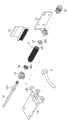
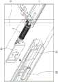
图1B显示本发明实施例的枢轴结构的爆炸图。FIG. 1B shows an exploded view of the pivot structure according to the embodiment of the present invention.
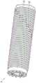
图2A显示本发明实施例的信号连接单元的组合图。FIG. 2A shows a combined diagram of a signal connection unit according to an embodiment of the present invention.
图2B显示本发明实施例的信号连接单元的爆炸示意图。FIG. 2B shows an exploded schematic diagram of the signal connection unit according to the embodiment of the present invention.
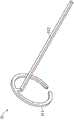
图3A显示本发明实施例的导电组件的细部结构。FIG. 3A shows the detailed structure of the conductive element according to the embodiment of the present invention.
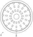
图3B显示本发明实施例的分隔环的细部结构。FIG. 3B shows the detailed structure of the separating ring according to the embodiment of the present invention.
图3C显示本发明实施例的套接部的导角面。FIG. 3C shows the chamfered surface of the socket part according to the embodiment of the present invention.
图3D显示本发明实施例的限位孔的圈数为3圈的情形。FIG. 3D shows a situation where the number of turns of the limiting hole according to the embodiment of the present invention is 3 turns.
图3E显示本发明实施例的限位孔交错排列的情形。FIG. 3E shows the staggered arrangement of the limiting holes according to the embodiment of the present invention.
图4A显示本发明实施例的转向连接器的细部结构。FIG. 4A shows the detailed structure of the steering connector according to the embodiment of the present invention.
图4B显示本发明实施例的枢接连接器导体。FIG. 4B shows a pivot connector conductor according to an embodiment of the present invention.
图4C显示本发明另一实施例的枢接连接器导体。FIG. 4C shows a pivot connector conductor according to another embodiment of the present invention.
图4D显示本发明实施例的轴杆的细部结构。FIG. 4D shows the detailed structure of the shaft according to the embodiment of the present invention.
图5A显示本发明一实施例的圈状部,其上形成有一缺口。FIG. 5A shows a ring-shaped portion according to an embodiment of the present invention, with a notch formed thereon.
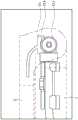
图5B显示本发明实施例的第二部件相对第一部件于第一方位的情形。FIG. 5B shows a situation in which the second component of the embodiment of the present invention is in a first orientation relative to the first component.
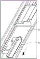
图5C显示本发明实施例的第二部件相对第一部件于第二方位的情形。FIG. 5C shows a situation in which the second component of the embodiment of the present invention is in a second orientation relative to the first component.
图6A、图6B以及图6C显示本发明实施例的信号连接单元的制造方法FIG. 6A , FIG. 6B and FIG. 6C illustrate a method for manufacturing a signal connection unit according to an embodiment of the present invention
图7A、图7B以及图7C显示本发明实施例的插销单元及枢转连接架。7A, 7B and 7C show a latch unit and a pivoting connecting frame according to an embodiment of the present invention.
附图标记如下:The reference numbers are as follows:
D~电子装置D~Electronic device
1~第一部件1 to the first part
11~第一信号线11~The first signal line
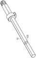
12~轴杆12~Shaft
121~轴杆止挡部121~Spindle stopper
122~截面122~section
13~转向连接器13~Steering connector
131~转向导体131~Steering conductor
132~转向连接器通孔132~Steering connector through hole
14~支架14~Bracket
141~支架止挡部141~Bracket stopper
15~枢转连接架15~Pivot connecting frame
16~扭力单元16~torque unit
2~第二部件2 to the second part
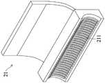
21~枢接连接器21~Pivot connector
211~枢接连接器导体211~Pivot connector conductor
22~插销单元22~Plug unit
3~信号连接单元3~Signal connection unit
301~连接单元通孔301~connection unit through hole
31~导电组件31~Conductive components
311~圈状部311~Circle part
312~延伸部312~Extension
314~缺口314~Gap
32~分隔环32~Separation ring
321~限位孔321~Limiting hole
322~分隔部322~Separator
323~套接部323~Socket
324~导角面324~Chamfer surface
33~第一导电组件33~The first conductive component
331~第一圈状部331~First circle part
332~第一延伸部332~The first extension
333~第一弯折部333~The first bending part
34~第二导电组件34~Second conductive component
341~第二圈状部341~Second ring-shaped part
342~第二延伸部342~Second extension
343~第二弯折部343~Second bending part
35~第一分隔环35~First Separator Ring
351~第一限位孔351~The first limit hole
36~第二分隔环36~Second Separation Ring
361~第二限位孔361~Second limit hole
37~第一固定环37~The first fixing ring
38~第二固定环38~Second fixing ring
381~第一侧381~First side
382~第二侧382~Second side
383~固定环限位孔383~Fixing ring limit hole
具体实施方式Detailed ways
图1A显示本发明实施例的具有枢轴结构的电子装置D。图1B显示本发明实施例的枢轴结构的爆炸图。参照图1A、图1B,本发明实施例的具有枢轴结构的电子装置D包括一第一部件1以及一第二部件2。第一部件1包括一第一信号线11、一轴杆12、一转向连接器13以及一信号连接单元3。第一信号线11电性连接第一部件1,转向连接器13耦接该第一信号线11。该转向连接器13套设于该轴杆12上。信号连接单元3套设于该轴杆12之上。FIG. 1A shows an electronic device D having a pivot structure according to an embodiment of the present invention. FIG. 1B shows an exploded view of the pivot structure according to the embodiment of the present invention. Referring to FIGS. 1A and 1B , an electronic device D with a pivot structure according to an embodiment of the present invention includes a
参照图1B,在一实施例中,该第一部件1还包括一扭力单元16,该扭力单元16套设于该轴杆12之上以提供扭力。Referring to FIG. 1B , in one embodiment, the
图2A显示信号连接单元3的组合图,图2B显示信号连接单元3的爆炸图。参照图2A、图2B,信号连接单元3包括多个导电组件31以及多个分隔环32。图3A显示导电组件31的细部结构。图3B显示分隔环32的细部结构。搭配参照图2A、图2B、图3A及图3B,导电组件31包括一第一导电组件33以及一第二导电组件34,该第一导电组件33包括一第一圈状部331以及一第一延伸部332,该第一圈状部331连接该第一延伸部332的一端,该第二导电组件34包括一第二圈状部341以及一第二延伸部342,该第二圈状部341连接该第二延伸部342的一端,该第二延伸部342平行于该第一延伸部332。分隔环32包括第一分隔环35以及一第二分隔环36,该第一分隔环35分隔该第一圈状部331以及该第二圈状部341,该第一分隔环35包括多个第一限位孔351,该第一延伸部332对应穿过其中之一该第一限位孔351,该第二分隔环36抵接该第二圈状部341,其中,该第二分隔环36包括多个第二限位孔361,该第一延伸部332对应穿过其中之一该第二限位孔361,该第二延伸部342对应穿过其中的另一该第二限位孔361,该第二分隔环36位于该转向连接器13与该第二圈状部341之间。FIG. 2A shows an assembled view of the
在图2B中,该各组件的位置及尺寸仅为示意,并未限制本发明,例如,在组装时,该第一延伸部332的实际长度较图2B所显示的为短。In FIG. 2B , the positions and dimensions of the components are only for illustration and do not limit the present invention. For example, during assembly, the actual length of the
再参照图1A、图1B,该第二部件2连接该第一部件1,并适于相对该第一部件1转动,该第二部件2包括一枢接连接器21,枢接连接器21电性连接第二部件2,该枢接连接器21连接该信号连接单元3并适于耦接该第一圈状部331以及该第二圈状部341。Referring to FIGS. 1A and 1B again, the
在一实施例中,该电子装置为笔记本电脑,该第一部件1可以为计算机主机,该第二部件2可以为屏幕,通过该信号连接单元3可电性连接计算机主机及屏幕。In one embodiment, the electronic device is a notebook computer, the
在上述实施例中,以该第一导电组件33以及该第二导电组件34为例,描述多个导电组件31与多个分隔环32之间的对应关系,然上述公开并未限制本发明,导电组件31的数量可以视需要变化。同样的,在上述实施例中,以该第一分隔环35以及该第二分隔环36为例,描述多个导电组件31与多个分隔环32之间的对应关系,然上述公开并未限制本发明,分隔环32的数量可以视需要变化。In the above-mentioned embodiment, the first
参照图3B,就细部结构而言,每一该分隔环32具有多个限位孔321,多个限位孔321沿该分隔环32的周向排列。在此实施例中,两两成对的多个限位孔321亦沿该分隔环32的径向排列。参照图3D,多个限位孔321的圈数可以为3圈。参照图3E,多个限位孔321也可以为交错排列。上述公开并未限制本发明。Referring to FIG. 3B , in terms of the detailed structure, each of the separating rings 32 has a plurality of limiting
搭配参照图3A、图3B,在一实施例中,每一分隔环32包括一分隔部322以及一套接部323,每一导电组件31包括一圈状部311以及一延伸部312,该圈状部311连接该延伸部312的一端,多个导电组件31的多个圈状部311至少部分对应套设于套接部323之上,至少部分的分隔环32夹设于两个圈状部311之间。参照图2B,在此实施例中,第一圈状部331并未套设于分隔环的套接部之上。Referring to FIGS. 3A and 3B, in one embodiment, each separating
参照图3C,在一实施例中,该套接部323包括一导角面324,该导角面324引导该圈状部311套设于该套接部323之上。Referring to FIG. 3C , in one embodiment, the
搭配参照图1A、图1B、图2A以及图2B,在一实施例中,该第一导电组件33包括一第一弯折部333,该第一弯折部333连接该第一延伸部332的另一端,该第二导电组件34包括一第二弯折部343,该第二弯折部343连接该第二延伸部342的另一端,该第一弯折部333以及该第二弯折部343位于该第二分隔环36与该转向连接器13之间。1A , FIG. 1B , FIG. 2A and FIG. 2B , in one embodiment, the first
搭配参照图1A、图1B、图2A以及图2B,在一实施例中,该第一弯折部333以及该第二弯折部343抵接该转向连接器13。借此,该第一弯折部333以及该第二弯折部343耦接该转向连接器13。Referring to FIG. 1A , FIG. 1B , FIG. 2A and FIG. 2B , in one embodiment, the
参照图2B,在一实施例中,该信号连接单元3还包括一第一固定环37以及一第二固定环38,该第一固定环37嵌合该第一分隔环35,该第二分隔环36抵接该第二固定环38的一第一侧381,该第一弯折部333以及该第二弯折部343抵接该第二固定环38的一第二侧382。Referring to FIG. 2B , in an embodiment, the
在本发明的实施例中,该导电组件为一体成形的金属组件,换言之,该圈状部、该延伸部以及该弯折部均一体成形。在一实施例中,该导电组件为金属件,该导电组件的整体表面均未覆以包覆材。然而,上述公开并未限制本发明。In an embodiment of the present invention, the conductive component is an integrally formed metal component, in other words, the ring-shaped portion, the extension portion and the bent portion are all integrally formed. In one embodiment, the conductive element is a metal piece, and the entire surface of the conductive element is not covered with a cladding material. However, the above disclosure does not limit the present invention.
参照图1A、图1B,在一实施例中,该第一部件1包括一第一支架14,该第一支架14包括一第一支架止挡部141,该轴杆12包括一轴杆止挡部121,该信号连接单元3以及该转向连接器13被夹设于该第一支架止挡部141以及该轴杆止挡部121之间。1A and FIG. 1B , in one embodiment, the
参照图4A,在一实施例中,该转向连接器13包括多个转向导体131,多个转向导体131弯折90度,借此耦接导电组件以及该第一信号线。参照图1B,在此实施例中,该转向连接器13仅连接单一的第一信号线,在不同的实施例中,该转向连接器13也可能同时连接多条第一信号线,该转向连接器13的形状也可能改变,上述公开并未限制本发明。多个转向导体131可直接连接该第一信号线,或通过弹性接脚等组件耦接该第一信号线。Referring to FIG. 4A , in one embodiment, the
在本发明的另一实施例中,导电组件及转向导体为一体成形的金属组件,换言之,每一导电组件的该圈状部、该延伸部以及该转向导体为一体成形,在本实施例中,导电组件不具有弯折部。In another embodiment of the present invention, the conductive component and the steering conductor are integrally formed metal components, in other words, the loop portion, the extension portion and the steering conductor of each conductive component are integrally formed, in this embodiment , the conductive component does not have a bent portion.
参照图4B、图4C,在一实施例中,该枢接连接器21还包括多个枢接连接器导体211,多个枢接连接器导体211对应接触多个导电组件的圈状部,多个枢接连接器导体211的形状可以为弧型(图4B)或长条型(图4C)。4B and 4C, in one embodiment, the
参照图4D,在一实施例中,该轴杆12的截面122非正圆。参照图4A,该转向连接器13包括一转向连接器通孔132。参照图1B,该信号连接单元3包括一连接单元通孔301。该转向连接器通孔132与该连接单元通孔301非正圆。该转向连接器13以及该信号连接单元3借此嵌合该轴杆12。Referring to FIG. 4D , in one embodiment, the
参照图5A,在一实施例中,该圈状部311可以形成有一缺口314。该第二部件2相对该第一部件1于一第一方位(图5B)以及一第二方位(图5C)之间转动,当该第二部件2位于该第一方位时,该枢接连接器21的其中一枢接连接器导体211对应于该缺口314,使该枢接连接器导体211与该圈状部311电性分离,使得包含该缺口314的该导电组件31不传递信号,而当该第一部件1位于该第二方位时,该枢接连接器21的所有枢接连接器导体211耦接该圈状部311,使得所有导电组件31可传递信号。借此,该电子装置可以提供屏幕自动休眠、屏幕自动点亮、调整音量大小、静音或自动屏幕画面翻转、关闭窗口、使窗口放大为全屏幕等功能。该第二部件2可相对该第一部件1转动于0~360度之间。在另一实施例中(图上未显示),可于该信号连接单元3的多个导电组件31的多个圈状部311上分别形成不同位置的缺口,使该第二部件2相对该第一部件1转动于不同方位时,该枢接连接器21的不同枢接连接器导体211分别对应多个缺口而与对应的该圈状部311电性分离,因而使包含该缺口的该导电组件31不传递信号,使得该电子装置可视需要切换提供上述多种功能。Referring to FIG. 5A , in one embodiment, a
搭配参照前述图式及描述,整体而言,借由信号连接单元3可电性连接第一部件1以及第二部件2,依序为第一部件1、第一信号线11、转向连接器13的转向导体131、信号连接单元3的导电组件31、枢接连接器21的连接器导体211、以及第二部件2。同时,借由信号连接单元3使第二部件2可相对于第一部件1转动。再者,借由信号连接单元3可使第一部件1以及第二部件2在不同相对位置时,使电子装置可以提供屏幕自动休眠、屏幕自动点亮、调整音量大小、静音或自动屏幕画面翻转、关闭窗口、使窗口放大为全屏幕等功能。With reference to the aforementioned drawings and descriptions, as a whole, the
参照图6A,在一实施例中,本发明实施例另提供一种信号连接单元的制造方法,包括下述步骤。首先,提供多个导电组件,导电组件包括一第一导电组件33以及一第二导电组件34,该第一导电组件33包括一第一圈状部331以及一第一延伸部332,该第一圈状部331连接该第一延伸部332的一端,该第二导电组件34包括一第二圈状部341以及一第二延伸部342,该第二圈状部341连接该第二延伸部342的一端。接着,提供多个分隔环,多个分隔环包括第一分隔环35以及一第二分隔环36,该第一分隔环35包括多个第一限位孔351,该第二分隔环36包括多个第二限位孔361。再,将该第一延伸部332穿过其中之一该第一限位孔351,并将该第一圈状部331连接该第一分隔环35。接着,将该第二延伸部342穿过其中之一该第二限位孔361,并将该第二圈状部341连接该第二分隔环36。再,将该第一延伸部332穿过其中的另一该第二限位孔361,并使该第二圈状部341抵接该第一分隔环35。Referring to FIG. 6A , in an embodiment, an embodiment of the present invention further provides a method for manufacturing a signal connection unit, which includes the following steps. First, a plurality of conductive components are provided. The conductive components include a first
在堆栈足够数量的导电组件以及分隔环之后。参照图6B,提供一第一固定环37以及一第二固定环38,该第二固定环38包括多个固定环限位孔383(搭配参照图2B)。接着,将该第一固定环37嵌合其中之一该分隔环。接着,将该第一延伸部332穿过其中之一该固定环限位孔383,并将该第二延伸部342穿过其中的另一该固定环限位孔383。在所有导电组件的延伸部均穿过分别的固定环限位孔后,参照图6C,齐平截断该第一延伸部332、该第二延伸部342以及各导电组件的各延伸部。接着,弯折该第一延伸部332、该第二延伸部342以及各该延伸部的自由端,以在该第一延伸部332的自由端形成一第一弯折部333,在该第二延伸部342的自由端形成一第二弯折部343,及在各该延伸部的自由端形成一弯折部。多个导电组件的圈状部及多个分隔环夹设于该第一固定环37与该第二固定环38之间。After stacking a sufficient number of conductive components and spacer rings. Referring to FIG. 6B , a
参照图1A、图1B、图7A、图7B以及图7C,在一实施例中,该第一部件1还包括一枢转连接架15,该枢转连接架15枢接该轴杆12,该第二部件2包括一插销单元22,该插销单元22以可拆卸的方式连接该枢转连接架15。参照图7A,该第二部件2通过该插销单元22连接该第一部件1的该枢转连接架15。当欲分离该第一部件1以及该第二部件2时,仅需要拨动该插销单元22(图7B),即可使该第一部件1分离该第二部件2(图7C)。1A, FIG. 1B, FIG. 7A, FIG. 7B and FIG. 7C, in one embodiment, the
在本发明的实施例中,通过信号连接单元直接接触枢接连接器的方式,可取代公知的电线,提供第一部件与第二部件之间的电性连接。因此可避免公知的走线空间不足或线材磨损等问题。此外,本发明实施例的导电组件可快速简易的结合分隔环,实现多接脚(pin)的信号连接单元。另,搭配导电组件上的缺口,本发明实施例的电子装置可以提供屏幕自动休眠、屏幕自动点亮、调整音量大小、静音或自动屏幕画面翻转、关闭窗口、使窗口放大为全屏幕等功能,而毋须额外的感测组件。In the embodiment of the present invention, the electrical connection between the first part and the second part can be provided by the signal connection unit directly contacting the pivot connector instead of the known wire. Therefore, the well-known problems of insufficient wiring space or wire wear and the like can be avoided. In addition, the conductive component of the embodiment of the present invention can be quickly and easily combined with the spacer ring to realize a multi-pin signal connection unit. In addition, with the notch on the conductive component, the electronic device of the embodiment of the present invention can provide functions such as automatic screen sleep, automatic screen lighting, volume adjustment, mute or automatic screen image flip, closing the window, and enlarging the window to a full screen, etc. No additional sensing components are required.
虽然本发明已以具体的较佳实施例公开如上,然其并非用以限定本发明,任何本领域普通技术人员,在不脱离本发明的精神和范围内,仍可作些许的更动与润饰,因此本发明的保护范围当视所附的权利要求所界定为准。Although the present invention has been disclosed above with specific preferred embodiments, it is not intended to limit the present invention. Any person of ordinary skill in the art can still make some changes and modifications without departing from the spirit and scope of the present invention. Therefore, the protection scope of the present invention should be defined by the appended claims.
Claims (16)
Applications Claiming Priority (2)
| Application Number | Priority Date | Filing Date | Title |
|---|---|---|---|
| TW107116278ATWI675282B (en) | 2018-05-14 | 2018-05-14 | Electronic device with hinge structure and method for manufacturing signal connection unit thereof |
| TW107116278 | 2018-05-14 |
Publications (2)
| Publication Number | Publication Date |
|---|---|
| CN110488915A CN110488915A (en) | 2019-11-22 |
| CN110488915Btrue CN110488915B (en) | 2020-12-11 |
Family
ID=65011604
Family Applications (1)
| Application Number | Title | Priority Date | Filing Date |
|---|---|---|---|
| CN201810552339.0AActiveCN110488915B (en) | 2018-05-14 | 2018-05-31 | Electronic device with pivot structure and method for manufacturing the same |
Country Status (3)
| Country | Link |
|---|---|
| US (1) | US10185369B1 (en) |
| CN (1) | CN110488915B (en) |
| TW (1) | TWI675282B (en) |
Families Citing this family (4)
| Publication number | Priority date | Publication date | Assignee | Title |
|---|---|---|---|---|
| US10559931B2 (en)* | 2018-04-23 | 2020-02-11 | Ford Global Technologies, Llc | High circuit count electrical connector |
| US10788865B1 (en)* | 2019-04-26 | 2020-09-29 | Dell Products L.P. | Information handling system dual pivot hinge signal path |
| TWI748704B (en)* | 2020-10-23 | 2021-12-01 | 華碩電腦股份有限公司 | Hinge structure and electronic device |
| CN115095594B (en)* | 2022-06-10 | 2024-07-16 | 苏州三星电子电脑有限公司 | Rotating shaft device and electronic equipment with same |
Citations (3)
| Publication number | Priority date | Publication date | Assignee | Title |
|---|---|---|---|---|
| TW200907643A (en)* | 2007-08-10 | 2009-02-16 | Inventec Corp | Portable computer with rotatable screen and rotateabe electronic connector thereof. |
| TW201434376A (en)* | 2013-01-31 | 2014-09-01 | Hewlett Packard Development Co | Hinge assembly |
| TWI612871B (en)* | 2014-09-26 | 2018-01-21 | 仁寶電腦工業股份有限公司 | Electronic device |
Family Cites Families (18)
| Publication number | Priority date | Publication date | Assignee | Title |
|---|---|---|---|---|
| US3860312A (en)* | 1973-06-13 | 1975-01-14 | Welco Ind Inc | Electrical slip coupling |
| JP3373730B2 (en)* | 1996-05-23 | 2003-02-04 | 株式会社ヨコオ | Hinge connector and electronic device using the hinge connector |
| JP2000321990A (en) | 1999-05-06 | 2000-11-24 | Nec Yonezawa Ltd | Display device with turning mechanism |
| CN100511875C (en)* | 2002-05-24 | 2009-07-08 | 莫列斯公司 | Hinge connector for electronic device |
| KR100498328B1 (en)* | 2002-08-01 | 2005-07-01 | 엘지전자 주식회사 | Rotatable fpcb connector structure for folder type mobile-phone |
| JP2005348341A (en)* | 2004-06-07 | 2005-12-15 | Casio Comput Co Ltd | Portable electronic devices |
| CN101931158B (en)* | 2009-06-24 | 2012-12-26 | 莫列斯公司 | Pivot electric connector combination and electronic device with same |
| CN103291735A (en)* | 2012-02-22 | 2013-09-11 | 英业达股份有限公司 | Electronic device and its biaxial pivot |
| US20140220790A1 (en)* | 2013-02-01 | 2014-08-07 | Chung-Yu Lee | Electrical Hinge Assembly and Electric Device using the Same |
| TWI539683B (en)* | 2013-04-26 | 2016-06-21 | 宏碁股份有限公司 | Connector and the method for assembling |
| CN104806858A (en)* | 2014-01-24 | 2015-07-29 | 华硕电脑股份有限公司 | Limiting structure and electronic device with limiting structure |
| US9450289B2 (en)* | 2014-03-10 | 2016-09-20 | Apple Inc. | Electronic device with dual clutch barrel cavity antennas |
| DE102015116490A1 (en)* | 2014-11-19 | 2016-05-19 | Rosenberger Hochfrequenztechnik Gmbh & Co. Kg | Magnetic connection device |
| US9444525B2 (en)* | 2014-12-19 | 2016-09-13 | Dell Products L.P. | Waveguide for near field communication |
| WO2016183354A1 (en)* | 2015-05-12 | 2016-11-17 | Kohen Ran Roland | Smart quick connect device for electrical fixtures |
| US10908652B2 (en)* | 2016-08-19 | 2021-02-02 | Microsoft Technology Licensing, Llc | Modular hinge for a computing device |
| CN106502327B (en)* | 2016-10-25 | 2019-05-03 | 合肥联宝信息技术有限公司 | Pedestal and electronic equipment |
| US10627857B2 (en)* | 2016-11-01 | 2020-04-21 | Lenovo (Singapore) Pte. Ltd. | Electronic device with rotatable and translational display unit |
- 2018
- 2018-05-14TWTW107116278Apatent/TWI675282B/enactive
- 2018-05-31CNCN201810552339.0Apatent/CN110488915B/enactiveActive
- 2018-07-13USUS16/035,567patent/US10185369B1/enactiveActive
Patent Citations (3)
| Publication number | Priority date | Publication date | Assignee | Title |
|---|---|---|---|---|
| TW200907643A (en)* | 2007-08-10 | 2009-02-16 | Inventec Corp | Portable computer with rotatable screen and rotateabe electronic connector thereof. |
| TW201434376A (en)* | 2013-01-31 | 2014-09-01 | Hewlett Packard Development Co | Hinge assembly |
| TWI612871B (en)* | 2014-09-26 | 2018-01-21 | 仁寶電腦工業股份有限公司 | Electronic device |
Also Published As
| Publication number | Publication date |
|---|---|
| CN110488915A (en) | 2019-11-22 |
| US10185369B1 (en) | 2019-01-22 |
| TW201947346A (en) | 2019-12-16 |
| TWI675282B (en) | 2019-10-21 |
Similar Documents
| Publication | Publication Date | Title |
|---|---|---|
| CN110488915B (en) | Electronic device with pivot structure and method for manufacturing the same | |
| US8593800B2 (en) | Electronic equipment with hinge mechanism | |
| US7267552B2 (en) | Signal transmission cable with adaptive contact pin reference | |
| US20060160377A1 (en) | Electronic device having a pivotable electrical connector, and electrical connector assembly | |
| CN104514799B (en) | Pivot structure and electronic device with same | |
| CN103119795A (en) | electrical connector | |
| US7113812B2 (en) | Rotatable wireless transceiver device | |
| CN101610653B (en) | Electronic equipment and communication unit thereof | |
| US6945818B2 (en) | Coaxial connector | |
| TWI496530B (en) | Hinge assembly and electronic device | |
| CN108736276B (en) | RF Connector | |
| CN104871376A (en) | Connector | |
| WO2003107491A1 (en) | Coaxial cable with plug | |
| CN102780103A (en) | Connector mechanism for connecting board card | |
| USRE40881E1 (en) | Rotational split adaptor | |
| CN109390817A (en) | Coaxial cable connector with window and the coaxial connector device using it | |
| CN107785747B (en) | Electric connector | |
| US8235758B2 (en) | Rotatable plug | |
| CN114597724B (en) | Electrical connection devices and photographic equipment | |
| KR101893953B1 (en) | folderable hinge device through which wire passes | |
| US9572274B2 (en) | Securing mechanism | |
| CN101073180A (en) | Antenna joint connector | |
| US6807436B2 (en) | Orientation-adjusting device for properly orienting wireless transceiver in confined space | |
| JP6955652B2 (en) | Connection terminal device | |
| CN101710249A (en) | Notebook computer |
Legal Events
| Date | Code | Title | Description |
|---|---|---|---|
| PB01 | Publication | ||
| PB01 | Publication | ||
| SE01 | Entry into force of request for substantive examination | ||
| SE01 | Entry into force of request for substantive examination | ||
| GR01 | Patent grant | ||
| GR01 | Patent grant |