CN110464465B - Auxiliary robot for total knee joint replacement operation - Google Patents
Auxiliary robot for total knee joint replacement operationDownload PDFInfo
- Publication number
- CN110464465B CN110464465BCN201910750822.4ACN201910750822ACN110464465BCN 110464465 BCN110464465 BCN 110464465BCN 201910750822 ACN201910750822 ACN 201910750822ACN 110464465 BCN110464465 BCN 110464465B
- Authority
- CN
- China
- Prior art keywords
- clamping
- light source
- muscle tissue
- leg
- skin
- Prior art date
- Legal status (The legal status is an assumption and is not a legal conclusion. Google has not performed a legal analysis and makes no representation as to the accuracy of the status listed.)
- Expired - Fee Related
Links
Images


Classifications
- A—HUMAN NECESSITIES
- A61—MEDICAL OR VETERINARY SCIENCE; HYGIENE
- A61B—DIAGNOSIS; SURGERY; IDENTIFICATION
- A61B17/00—Surgical instruments, devices or methods
- A61B17/02—Surgical instruments, devices or methods for holding wounds open, e.g. retractors; Tractors
- A—HUMAN NECESSITIES
- A61—MEDICAL OR VETERINARY SCIENCE; HYGIENE
- A61B—DIAGNOSIS; SURGERY; IDENTIFICATION
- A61B17/00—Surgical instruments, devices or methods
- A61B17/14—Surgical saws
- A—HUMAN NECESSITIES
- A61—MEDICAL OR VETERINARY SCIENCE; HYGIENE
- A61B—DIAGNOSIS; SURGERY; IDENTIFICATION
- A61B17/00—Surgical instruments, devices or methods
- A61B17/16—Instruments for performing osteoclasis; Drills or chisels for bones; Trepans
- A61B17/1604—Chisels; Rongeurs; Punches; Stamps
- A—HUMAN NECESSITIES
- A61—MEDICAL OR VETERINARY SCIENCE; HYGIENE
- A61B—DIAGNOSIS; SURGERY; IDENTIFICATION
- A61B17/00—Surgical instruments, devices or methods
- A61B17/32—Surgical cutting instruments
- A61B17/3209—Incision instruments
- A61B17/32093—Incision instruments for skin incisions
- A—HUMAN NECESSITIES
- A61—MEDICAL OR VETERINARY SCIENCE; HYGIENE
- A61B—DIAGNOSIS; SURGERY; IDENTIFICATION
- A61B18/00—Surgical instruments, devices or methods for transferring non-mechanical forms of energy to or from the body
- A61B18/04—Surgical instruments, devices or methods for transferring non-mechanical forms of energy to or from the body by heating
- A61B18/12—Surgical instruments, devices or methods for transferring non-mechanical forms of energy to or from the body by heating by passing a current through the tissue to be heated, e.g. high-frequency current
- A—HUMAN NECESSITIES
- A61—MEDICAL OR VETERINARY SCIENCE; HYGIENE
- A61B—DIAGNOSIS; SURGERY; IDENTIFICATION
- A61B34/00—Computer-aided surgery; Manipulators or robots specially adapted for use in surgery
- A61B34/20—Surgical navigation systems; Devices for tracking or guiding surgical instruments, e.g. for frameless stereotaxis
- A—HUMAN NECESSITIES
- A61—MEDICAL OR VETERINARY SCIENCE; HYGIENE
- A61B—DIAGNOSIS; SURGERY; IDENTIFICATION
- A61B34/00—Computer-aided surgery; Manipulators or robots specially adapted for use in surgery
- A61B34/30—Surgical robots
- A—HUMAN NECESSITIES
- A61—MEDICAL OR VETERINARY SCIENCE; HYGIENE
- A61B—DIAGNOSIS; SURGERY; IDENTIFICATION
- A61B34/00—Computer-aided surgery; Manipulators or robots specially adapted for use in surgery
- A61B34/70—Manipulators specially adapted for use in surgery
- A—HUMAN NECESSITIES
- A61—MEDICAL OR VETERINARY SCIENCE; HYGIENE
- A61B—DIAGNOSIS; SURGERY; IDENTIFICATION
- A61B90/00—Instruments, implements or accessories specially adapted for surgery or diagnosis and not covered by any of the groups A61B1/00 - A61B50/00, e.g. for luxation treatment or for protecting wound edges
- A61B90/10—Instruments, implements or accessories specially adapted for surgery or diagnosis and not covered by any of the groups A61B1/00 - A61B50/00, e.g. for luxation treatment or for protecting wound edges for stereotaxic surgery, e.g. frame-based stereotaxis
- A61B90/14—Fixators for body parts, e.g. skull clamps; Constructional details of fixators, e.g. pins
- A—HUMAN NECESSITIES
- A61—MEDICAL OR VETERINARY SCIENCE; HYGIENE
- A61B—DIAGNOSIS; SURGERY; IDENTIFICATION
- A61B34/00—Computer-aided surgery; Manipulators or robots specially adapted for use in surgery
- A61B34/20—Surgical navigation systems; Devices for tracking or guiding surgical instruments, e.g. for frameless stereotaxis
- A61B2034/2046—Tracking techniques
- A61B2034/2055—Optical tracking systems
- A—HUMAN NECESSITIES
- A61—MEDICAL OR VETERINARY SCIENCE; HYGIENE
- A61B—DIAGNOSIS; SURGERY; IDENTIFICATION
- A61B34/00—Computer-aided surgery; Manipulators or robots specially adapted for use in surgery
- A61B34/20—Surgical navigation systems; Devices for tracking or guiding surgical instruments, e.g. for frameless stereotaxis
- A61B2034/2046—Tracking techniques
- A61B2034/2065—Tracking using image or pattern recognition
Landscapes
- Health & Medical Sciences (AREA)
- Surgery (AREA)
- Life Sciences & Earth Sciences (AREA)
- Engineering & Computer Science (AREA)
- Animal Behavior & Ethology (AREA)
- General Health & Medical Sciences (AREA)
- Nuclear Medicine, Radiotherapy & Molecular Imaging (AREA)
- Veterinary Medicine (AREA)
- Biomedical Technology (AREA)
- Heart & Thoracic Surgery (AREA)
- Medical Informatics (AREA)
- Molecular Biology (AREA)
- Public Health (AREA)
- Oral & Maxillofacial Surgery (AREA)
- Robotics (AREA)
- Dentistry (AREA)
- Otolaryngology (AREA)
- Physics & Mathematics (AREA)
- Plasma & Fusion (AREA)
- Neurosurgery (AREA)
- Pathology (AREA)
- Dermatology (AREA)
- Orthopedic Medicine & Surgery (AREA)
- Manipulator (AREA)
Abstract
Translated fromChinese
Description
Translated fromChinese技术领域technical field
本发明属于机器人技术领域,具体涉及一种全膝关节置换手术辅助机器人。The invention belongs to the technical field of robots, and in particular relates to an auxiliary robot for total knee joint replacement surgery.
背景技术Background technique
随着工业技术的突飞猛进,机器人技术得到了快速的发展,其中机器人技术进入医疗领域,给医疗领域带来了新的重大技术变革。在骨外科领域,特别是全膝关节置换手术,手术效果过于依赖外科医生的经验,这无疑加大了手术效果的不稳定性。比如医生在切割关节骨骼等多项步骤中,医生和患者双方在过程中都难免会出现小状况,比如咳嗽、疲劳,定位精度不够或测量误差等,使植入关节的位置超出允许的标准范围,影响手术精准度。With the rapid development of industrial technology, robot technology has developed rapidly, among which robot technology has entered the medical field, bringing new major technological changes to the medical field. In the field of orthopedic surgery, especially total knee replacement surgery, the surgical effect relies too much on the experience of the surgeon, which undoubtedly increases the instability of the surgical effect. For example, when a doctor cuts joint bones and other steps, both the doctor and the patient will inevitably experience minor problems during the process, such as coughing, fatigue, insufficient positioning accuracy or measurement errors, etc., so that the position of the implanted joint exceeds the allowable standard range. , affecting the accuracy of surgery.
机器人技术被应用到全膝关节置换手术中后,可以实现高精度的手术定位,高精度的切削与运动控制,避免由于人手震颤和疲劳而引起的手术操作误差等缺点,提高了手术操作精度,同时机器人系统中新型手术工具的使用增加了手术操作的灵活性与效率;机器人技术的应用降低了医生的劳动强度,使医生将更多的精力投入到手术操作中,降低了劳动力成本;机器人系统建立多传感器检测与反馈机制,保证了手术的安全性;机器人技术应用到手术中会更加规范手术操作,提高了手术的质量,所以设计一种全膝关节置换手术辅助机器人极为必要。After robotic technology is applied to total knee replacement surgery, it can achieve high-precision surgical positioning, high-precision cutting and motion control, avoid the shortcomings of surgical operation errors caused by hand tremor and fatigue, and improve the accuracy of surgical operations. At the same time, the use of new surgical tools in the robotic system increases the flexibility and efficiency of surgical operations; the application of robotic technology reduces the labor intensity of doctors, enables doctors to devote more energy to surgical operations, and reduces labor costs; robotic systems The establishment of a multi-sensor detection and feedback mechanism ensures the safety of the operation; the application of robotic technology to the operation will standardize the operation and improve the quality of the operation, so it is extremely necessary to design an auxiliary robot for total knee replacement surgery.
发明内容SUMMARY OF THE INVENTION
本发明所要解决的技术问题在于针对上述现有技术中的不足,提供一种全膝关节置换手术辅助机器人,既可以切开膝关节外皮肤并止血,又可以外翻创口,实现全膝关节切除与钻孔置换的功能。The technical problem to be solved by the present invention is to provide an auxiliary robot for total knee replacement surgery, which can not only incise the outer skin of the knee joint to stop bleeding, but also valgus the wound to realize total knee joint resection. Replacement function with drilled holes.
本发明采用以下技术方案:The present invention adopts following technical scheme:
一种全膝关节置换手术辅助机器人,包括:An auxiliary robot for total knee replacement surgery, comprising:
具有七个关节的皮肤肌肉组织翻夹机械臂,用于打开切口处皮肤肌肉组织,包括对称设置的左侧皮肤肌肉组织翻夹机械臂和右侧皮肤肌肉组织翻夹机械臂;A skin and muscle tissue flipping mechanical arm with seven joints, used to open the skin and muscle tissue at the incision, including a symmetrically arranged left skin and muscle tissue flipping mechanical arm and a right skin and muscle tissue flipping mechanical arm;
具有七个关节的手术机械臂,用于全膝关节置换手术中的皮肤切开、膝盖骨立体切削造型、膝盖骨连接处钻孔和手术中电刀止血;A surgical robotic arm with seven joints, used for skin incision in total knee replacement surgery, three-dimensional cutting of the kneecap, drilling of the patella joint, and electrocautery for hemostasis during surgery;
腿部支撑夹紧机械臂,用于手术中大腿与小腿的固定,包括结构相同、相对设置的小腿支撑夹紧机械臂和大腿支撑夹紧机械臂;The leg support and clamping robot arm is used for the fixation of the thigh and the lower leg during the operation, including the lower leg support clamping robot arm and the thigh support clamping robot arm with the same structure and oppositely arranged;
立体视觉与光源机械臂,设置有双目摄像头及补充光源组件,用于术中视觉识别;Stereo vision and light source robotic arm, equipped with binocular camera and supplementary light source components for intraoperative visual recognition;
支架立柱,用于支撑机器人,支架立柱包括两个,两个支架立柱之间设置有支架连接板和支架盖板,支架连接板用于固定左侧皮肤肌肉组织翻夹机械臂、右侧皮肤肌肉组织翻夹机械臂、手术机械臂、小腿支撑夹紧机械臂、大腿支撑夹紧机械臂和立体视觉与光源机械臂;左侧皮肤肌肉组织翻夹机械臂与右侧皮肤肌肉组织翻夹机械臂设置在支架立柱的一侧,对称分布于腿部支撑夹紧机械臂的两边,手术机械臂设置在支架立柱的另一侧,支架盖板上设置有顶灯,立体视觉与光源机械臂位于顶灯的下方。The bracket column is used to support the robot. The bracket column includes two bracket columns. A bracket connecting plate and a bracket cover plate are arranged between the two bracket columns. The bracket connecting plate is used to fix the left skin and muscle tissue flipping mechanical arm and the right skin muscle. Tissue flipping robotic arm, surgical robotic arm, calf support gripping robotic arm, thigh support gripping robotic arm, and stereo vision and light source robotic arm; left skin and muscle tissue flipping robotic arm and right skin and muscle tissue flipping robotic arm It is arranged on one side of the bracket column, symmetrically distributed on both sides of the leg support and clamping mechanical arm, the surgical robot arm is arranged on the other side of the bracket column, the bracket cover is provided with a top light, and the stereo vision and light source mechanical arms are located at the top of the light. below.
具体的,皮肤肌肉组织翻夹机械臂包括第四皮肤肌肉组织翻夹机臂连杆,第四皮肤肌肉组织翻夹机臂连杆的上端通过第五皮肤肌肉组织翻夹机臂舵机与支架连接板连接,下端通过第四皮肤肌肉组织翻夹机臂舵机与第三皮肤肌肉组织翻夹机臂连杆的后端连接,第三皮肤肌肉组织翻夹机臂连杆的前端通过第三皮肤肌肉组织翻夹机臂舵机与第二皮肤肌肉组织翻夹机臂连杆的后端连接,第二皮肤肌肉组织翻夹机臂连杆的前端通过第二皮肤肌肉组织翻夹机臂舵机与第一皮肤肌肉组织夹紧组件连杆的后端连接,第一皮肤肌肉组织夹紧组件连杆的前端与第一皮肤肌肉组织夹紧组件旋转舵机连接,第一皮肤肌肉组织夹紧组件旋转舵机输出端与第一皮肤肌肉组织夹紧组件连接;第二皮肤肌肉组织翻夹机臂连杆下侧中部与第一皮肤肌肉组织翻夹机臂连杆的上端连接,第一皮肤肌肉组织翻夹机臂连杆的底端通过第一皮肤肌肉组织翻夹机臂舵机与第二皮肤肌肉组织夹紧组件连杆的后端连接,第二皮肤肌肉组织夹紧组件连杆的前端与第二皮肤肌肉组织夹紧组件旋转舵机连接,第二皮肤肌肉组织夹紧组件旋转舵机的输出端与第二皮肤肌肉组织夹紧组件连接。Specifically, the skin and muscle tissue flipping mechanical arm includes a fourth skin and muscle tissue flipping machine arm link, and the upper end of the fourth skin and muscle tissue flipping machine arm link passes through the fifth skin and muscle tissue flipping machine arm steering gear and bracket The connecting plate is connected, and the lower end is connected with the rear end of the third skin and muscle tissue turning arm connecting rod through the fourth skin and musculature turning arm steering gear, and the front end of the third skin and musculature turning turning arm connecting rod passes through the third skin and muscle tissue turning arm connecting rod. The steering gear of the skin and muscle tissue flipping machine arm is connected with the rear end of the second skin and muscle tissue flipping machine arm link, and the front end of the second skin and muscle tissue flipping machine arm connecting rod passes through the second skin and muscle tissue flipping machine arm rudder The machine is connected with the rear end of the connecting rod of the first skin and muscle tissue clamping assembly, and the front end of the first skin and muscle tissue clamping assembly connecting rod is connected with the rotating steering gear of the first skin and muscle tissue clamping assembly, and the first skin and muscle tissue is clamped The output end of the rotating steering gear of the component is connected with the first skin and muscle tissue clamping component; the middle part of the lower side of the connecting rod of the second skin and muscle tissue flipping machine arm is connected with the upper end of the connecting rod of the first skin and muscle tissue flipping machine arm, and the first skin and muscle tissue flipping machine arm connecting rod is connected. The bottom end of the connecting rod of the arm of the muscle tissue turning machine is connected with the rear end of the connecting rod of the second skin and muscle tissue clamping assembly through the steering gear of the arm of the first skin and muscle tissue turning machine, and the connecting rod of the second skin and muscle tissue clamping assembly is connected with the rear end of the connecting rod of the second skin and muscle tissue. The front end is connected with the rotating steering gear of the second skin and muscle tissue clamping component, and the output end of the rotating steering gear of the second skin and muscle tissue clamping component is connected with the second skin and muscle tissue clamping component.
进一步的,第一皮肤肌肉组织夹紧组件包括第一皮肤肌肉组织夹紧组件转接板,第一皮肤肌肉组织夹紧组件转接板垂直侧面通过螺钉固定在第二皮肤肌肉组织夹紧组件旋转舵机的输出端,转接板水平侧通过第一皮肤肌肉组织夹紧组件连接螺钉与第一皮肤肌肉组织夹紧组件底板相连;第一皮肤肌肉组织夹紧组件底板中部通过第一皮肤肌肉组织夹紧组件夹紧舵机分别与对称设置的两个第一皮肤肌肉组织夹紧组件齿轮连杆连接,每个第一皮肤肌肉组织夹紧组件齿轮连杆另一端通过一个第二连接销钉与对应的第一皮肤肌肉组织夹紧组件末端的一端连接,每个第一皮肤肌肉组织夹紧组件末端的中部通过第三连接销钉与第一连接板连接,第一连接板通过第四连接销钉与第一皮肤肌肉组织夹紧组件底板上侧连接,从而构成连杆机构;第一皮肤肌肉组织夹紧组件底板中部通过齿轮连杆分别与两个第一皮肤肌肉组织夹紧组件齿轮连杆啮合。Further, the first skin and muscle tissue clamping assembly comprises a first skin and muscle tissue clamping assembly adapter plate, and the vertical side of the first skin and muscle tissue clamping assembly adapter plate is fixed on the second skin and muscle tissue clamping assembly by screws to rotate. The output end of the steering gear, the horizontal side of the adapter plate is connected to the bottom plate of the first skin and muscle tissue clamping assembly through the connecting screw of the first skin and muscle tissue clamping assembly; the middle of the bottom plate of the first skin and muscle tissue clamping assembly passes through the first skin and muscle tissue. The clamping steering gear of the clamping component is respectively connected with the two symmetrically arranged gear links of the first skin and muscle tissue clamping components, and the other end of the gear link of each first skin and muscle tissue clamping component is connected to the corresponding gear link through a second connecting pin. One end of the end of the first skin and muscle tissue clamping assembly is connected, the middle part of the end of each first skin and muscle tissue clamping assembly is connected with the first connecting plate through a third connecting pin, and the first connecting plate is connected with the first connecting plate through a fourth connecting pin. A skin and muscle tissue clamping assembly is connected with the upper side of the bottom plate to form a link mechanism; the middle part of the bottom plate of the first skin and muscle tissue clamping assembly is respectively meshed with the gear links of the two first skin and muscle tissue clamping assemblies through gear links.
具体的,腿部支撑夹紧机械臂包括腿部立柱,腿部立柱上端与支架连接板上的腿部支撑夹紧机械臂方向舵机连接,下端一侧通过腿部支撑联接螺钉与腿部支撑机构连接,另一侧通过腿骨夹压组件方向舵机与腿部夹压机构连接。Specifically, the leg support clamping robotic arm includes a leg column, the upper end of the leg column is connected to the leg support clamping robotic arm rudder on the bracket connecting plate, and the lower end is connected to the leg support mechanism through the leg support connecting screw. The other side is connected with the leg crimping mechanism through the rudder of the leg bone crimping assembly.
进一步的,腿部支撑机构包括第一腿部方向舵机、第一腿部支撑连杆、第二腿部支撑连杆、腿部支撑转接杆、第二腿部方向舵机和腿部支撑槽;Further, the leg support mechanism includes a first leg steering gear, a first leg support link, a second leg support link, a leg support adapter rod, a second leg steering gear and a leg support groove;
第一腿部方向舵机上端通过螺钉与腿部立柱侧面连接,另一端与第二腿部支撑连杆成角度连接,第二腿部支撑连杆的末端通过第二腿部方向舵机与腿部支撑转接杆侧面连接,腿部支撑转接杆的顶端与腿部支撑槽的底端连接;The upper end of the steering gear of the first leg is connected to the side of the leg column through screws, and the other end is connected to the second leg support link at an angle, and the end of the second leg support link is connected to the leg through the second leg steering gear. The side of the adapter rod is connected, and the top end of the leg support adapter rod is connected with the bottom end of the leg support groove;
腿部夹压机构包括夹压组件电缸联接杆,夹压组件电缸联接杆的一端通过腿骨夹压组件方向舵机与腿部立柱侧边连接,另一端连接夹压组件推动电缸的底部,夹压组件推动电缸的顶部与腿骨夹压组件连接。The leg crimping mechanism includes the electric cylinder connecting rod of the crimping assembly. One end of the electric cylinder connecting rod of the crimping assembly is connected to the side of the leg column through the rudder of the leg bone crimping assembly, and the other end is connected to the bottom of the electric cylinder that pushes the electric cylinder. , the clamping component pushes the top of the electric cylinder to connect with the leg bone clamping component.
更进一步的,腿骨夹压组件包括腿骨夹压组件转接板,腿骨夹压组件转接板一侧中心与夹压组件推动电缸顶部连接,另一侧上部通过腿骨压紧与双目视觉组件旋转舵机与腿骨夹紧组件连接;Further, the leg bone clamping assembly includes a leg bone clamping assembly adapter plate, the center of one side of the leg bone clamping assembly adapter plate is connected to the top of the clamping assembly pushing electric cylinder, and the upper part of the other side is connected to the upper part of the leg bone compression assembly. The rotation servo of the binocular vision component is connected with the leg bone clamping component;
腿骨夹压组件转接板的另一侧下部通过螺钉与腿骨夹紧组件转接板垂直侧面连接,腿骨夹紧组件转接板水平侧通过腿骨夹紧组件连接螺钉与腿骨夹紧底座相连;The lower part of the other side of the legbone clamping assembly adapter plate is connected to the vertical side of the legbone clamping assembly adapter plate through screws, and the horizontal side of the legbone clamping assembly adapter plate is connected to the legbone clamp through the legbone clamping assembly. Screws Tightly connected to the base;
腿骨夹紧底座通过腿骨夹紧舵机分别与第一腿骨夹紧齿轮杆和第二腿骨夹紧齿轮杆连接,第一腿骨夹紧齿轮杆和第二腿骨夹紧齿轮杆对称设置,分别连接对应的第一腿骨夹紧末端和第二腿骨夹紧末端,其中,第二腿骨夹紧齿轮杆另一端通过第二腿骨夹紧连接销钉与第二腿骨夹紧末端的一端连接,第二腿骨夹紧末端的中部通过第三腿骨夹紧连接销钉与第二腿骨夹紧连接杆连接,第二腿骨夹紧连接杆通过第四腿骨夹紧连接销钉与腿骨夹紧底座上侧连接;The leg bone clamping base is respectively connected with the first leg bone clamping gear rod and the second leg bone clamping gear rod through the leg bone clamping servo, and the first leg bone clamping gear rod and the second leg bone clamping gear rod are respectively connected Symmetrically arranged, respectively connecting the corresponding first legbone clamping end and the second legbone clamping end, wherein the other end of the second legbone clamping gear rod is connected to the second legbone clip through the second legbone clamping connection pin One end of the tight end is connected, the middle part of the second leg bone clamping end is connected with the second leg bone clamping connecting rod through the third leg bone clamping connecting pin, and the second leg bone clamping connecting rod is clamped by the fourth leg bone The connecting pin is connected with the upper side of the leg bone clamping base;
腿骨夹紧组件包括腿骨压紧电缸连接板,腿骨压紧电缸连接板一端通过腿骨压紧与双目视觉组件旋转舵机与腿骨夹压组件转接板连接,中间通过腿骨压紧电缸旋转舵机与腿骨压紧电缸联接,另一端通过第一移动光源旋转舵机与双目视觉移动光源组件连接,腿骨压紧电缸的另一端连接腿骨压紧末端;The leg bone clamping assembly includes the leg bone compression electric cylinder connecting plate, one end of the leg bone compression electric cylinder connecting plate is connected with the binocular vision assembly through the leg bone compression, and the rotary servo and the leg bone clamping assembly adapter plate are connected through the middle. The leg bone pressing electric cylinder rotating servo is connected with the leg bone pressing electric cylinder, the other end is connected with the binocular vision moving light source assembly through the first moving light source rotating servo, and the other end of the leg bone pressing electric cylinder is connected with the leg bone pressing tight end;
双目视觉移动光源组件包括第一双目视觉移动光源组件转接板,第一双目视觉移动光源组件转接板侧面通过第一移动光源旋转舵机与腿骨压紧电缸连接板连接;上侧通过第一双目视觉移动光源组件连接螺钉与第一双目视觉移动光源组件连接板后端连接,第一双目视觉移动光源组件连接板中间通过第一移动光源连接螺钉与第一移动光源连接,第一双目视觉移动光源组件连接板前端通过第一双目视觉摄像头连接螺钉与第一双目视觉摄像头连接。The binocular vision moving light source assembly includes a first binocular vision moving light source assembly adapter plate, and the side surface of the first binocular vision moving light source assembly adapter plate is connected to the leg bone pressing electric cylinder connecting plate through the first moving light source rotating servo; The upper side is connected to the rear end of the first binocular vision moving light source assembly connecting plate through the first binocular vision moving light source assembly connecting screw, and the first binocular vision moving light source assembly connecting plate is connected to the first moving light source through the first moving light source connecting screw in the middle. The light source is connected, and the front end of the connecting plate of the first binocular vision mobile light source assembly is connected with the first binocular vision camera through the first binocular vision camera connecting screw.
具体的,手术机械臂机构包括第四手术机械臂连杆,第四手术机械臂连杆上端通过方向舵机与支架连接板连接,下端通过第三手术机械臂舵机与第三手术机械臂连杆的后端连接,第三手术机械臂连杆前端通过第二手术机械臂舵机与第二手术机械臂连杆后端连接,第二手术机械臂连杆的前端通过第一手术机械臂舵机与第一手术机械臂连杆的后端连接,第一手术机械臂连杆的前端与手术末端组件连接。Specifically, the surgical manipulator mechanism includes a fourth surgical manipulator connecting rod. The upper end of the fourth surgical manipulator connecting rod is connected to the bracket connecting plate through the steering gear, and the lower end is connected to the third surgical manipulator connecting rod through the third surgical manipulator steering gear. The front end of the connecting rod of the third surgical manipulator is connected to the rear end of the connecting rod of the second manipulator through the steering gear of the second manipulator, and the front end of the connecting rod of the second manipulator is connected by the steering gear of the first manipulator. It is connected with the rear end of the first surgical mechanical arm link, and the front end of the first surgical mechanical arm link is connected with the surgical end assembly.
进一步的,手术末端组件包括手术末端组件转向舵机,手术末端组件转向舵机上端通过螺钉与第一手术机械臂连杆的前端连接,手术末端组件转向舵机输出端与手术末端组件底座中心连接,手术末端组件底座底座四个伸出端分别通过舵机与腿骨切割机构、皮肤切割机构、腿骨钻孔机构、止血电刀机构连接;Further, the surgical terminal assembly includes a steering steering gear of the surgical terminal assembly, the upper end of the steering steering gear of the surgical terminal assembly is connected with the front end of the connecting rod of the first surgical manipulator through screws, and the output end of the steering steering gear of the surgical terminal assembly is connected to the center of the base of the surgical terminal assembly , the four protruding ends of the base of the base of the surgical end component are respectively connected with the leg bone cutting mechanism, the skin cutting mechanism, the leg bone drilling mechanism, and the hemostatic electric knife mechanism through the steering gear;
腿骨切割机构包括腿骨切割连接板,腿骨切割连接板一端通过腿骨切割部件转向舵机与手术末端组件底座连接,另一端通过腿骨切割驱动舵机与腿骨切割锯刀中心侧面连接;The leg bone cutting mechanism includes a leg bone cutting connecting plate. One end of the leg bone cutting connecting plate is connected to the base of the surgical end assembly through the steering servo of the leg bone cutting part, and the other end is connected to the central side of the leg bone cutting saw blade through the leg bone cutting driving servo. ;
皮肤切割机构包括皮肤切割连接板,皮肤切割连接板一端通过皮肤切割部件转向舵机与手术末端组件底座连接,另一端通过皮肤切割驱动舵机与皮肤切割锯刀中心侧面连接;The skin cutting mechanism includes a skin cutting connecting plate, one end of the skin cutting connecting plate is connected with the base of the surgical end assembly through the steering servo of the skin cutting part, and the other end is connected with the center side of the skin cutting saw blade through the skin cutting driving servo;
腿骨钻孔机构包括腿骨钻孔连接板,腿骨钻孔连接板一端通过腿骨钻孔部件转向舵机与手术末端组件底座连接,另一端垂面通过腿骨钻孔驱动舵机与腿骨钻孔钻头的上端连接;The leg bone drilling mechanism includes a leg bone drilling connection plate. One end of the leg bone drilling connection plate is connected to the base of the surgical end assembly through the leg bone drilling component steering servo, and the other end of the vertical surface drives the steering gear and the leg through the leg bone drilling. The upper end of the bone drilling bit is connected;
止血电刀机构包括止血电刀连接板,止血电刀连接板一端通过止血电刀部件转向舵机与手术末端组件底座连接,另一端垂面与止血电刀上端连接。The hemostatic electrosurgery mechanism includes a hemostatic electrosurgical connecting plate, one end of the hemostatic electrosurgical connecting plate is connected to the base of the surgical terminal assembly through the steering gear of the hemostasis electrosurgical unit, and the other end is vertically connected to the upper end of the hemostatic electrosurgical unit.
具体的,立体视觉与光源机构包括立体视觉光源机臂连接板,立体视觉光源机臂连接板后端通过螺钉与支架连接板连接,立体视觉光源机臂连接板前端通过第六立体视觉光源机臂舵机与第一立体视觉光源机臂转接板上端连接,第一立体视觉光源机臂转接板侧面通过第五体视觉光源机臂舵机与第四立体视觉光源机臂连杆上端连接,第四立体视觉光源机臂连杆下端通过第四体视觉光源机臂舵机与第三立体视觉光源机臂连杆后端连接,第三立体视觉光源机臂连杆前端通过第三体视觉光源机臂舵机与第二立体视觉光源机臂连杆后端连接,第二立体视觉光源机臂连杆前端通过第二体视觉光源机臂舵机与第一立体视觉光源机臂连杆后端连接,第一立体视觉光源机臂连杆前端通过第一立体视觉光源机臂舵机与第二立体视觉光源机臂转接板上端连接,第二立体视觉光源机臂转接板下部两端通过舵机分别与第二双目视觉移动光源组和第三双目视觉移动光源组连接。Specifically, the stereoscopic vision and light source mechanism includes a stereoscopic vision light source arm connecting plate, the rear end of the stereoscopic vision light source arm connecting plate is connected to the bracket connecting plate through screws, and the front end of the stereoscopic vision light source arm connecting plate is connected through the sixth stereoscopic vision light source arm. The steering gear is connected to the upper end of the first stereo vision light source arm adapter plate, and the side of the first stereo vision light source arm adapter plate is connected to the upper end of the fourth stereo vision light source arm connecting rod through the fifth stereo vision light source arm steering gear. The lower end of the arm connecting rod of the fourth stereo vision light source is connected with the rear end of the arm connecting rod of the third stereo vision light source through the arm steering gear of the fourth stereo vision light source, and the front end of the arm connecting rod of the third stereo vision light source passes through the third stereo vision light source The arm servo is connected with the rear end of the arm connecting rod of the second stereo vision light source, and the front end of the arm connecting rod of the second stereo vision light source is connected to the rear end of the arm connecting rod of the first stereo vision light source through the second stereo vision light source arm servo connection, the front end of the arm connecting rod of the first stereo vision light source is connected with the upper end of the arm adapter plate of the second stereo vision light source through the steering gear of the arm arm of the first stereo vision light source, and the lower ends of the arm adapter plate of the second stereo vision light source pass through The steering gear is respectively connected with the second binocular vision moving light source group and the third binocular vision moving light source group.
进一步的,第二双目视觉移动光源组和第三双目视觉移动光源组均包括第二双目视觉移动光源组连接板,第二双目视觉移动光源组连接板后端通过第二双目视觉光源组件旋转舵机与第二立体视觉光源机臂转接板一端连接,第二双目视觉移动光源组连接板中间通过第二移动光源连接板与第二移动光源连接,第二双目视觉移动光源组连接板前端通过第二双目视觉摄像头连接板与第二双目视觉摄像头连接。Further, the second binocular vision moving light source group and the third binocular vision moving light source group each include a second binocular vision moving light source group connecting plate, and the rear end of the second binocular vision moving light source group connecting plate passes through the second binocular vision moving light source group. The rotary steering gear of the visual light source assembly is connected with one end of the arm adapter plate of the second stereo vision light source, and the connecting plate of the second binocular vision moving light source group is connected to the second moving light source through the second moving light source connecting plate in the middle. The front end of the connecting plate of the mobile light source group is connected with the second binocular vision camera through the second binocular vision camera connecting plate.
与现有技术相比,本发明至少具有以下有益效果:Compared with the prior art, the present invention at least has the following beneficial effects:
本发明一种全膝关节置换手术辅助机器人,可以实现辅助医生开展全膝关节置换手术的功能,为全膝关节置换手术的精准高效提供了技术保障。手术机械臂机构包含皮肤切割部件、腿骨切割部件、腿骨钻孔部件、止血电刀部件,保证了全膝关节置换手术中相关操作的稳定高效;小腿支撑夹紧机械臂机构与大腿支撑夹紧机械臂机构相对布置,保证了手术时腿部的固定;左侧皮肤肌肉组织翻夹机械臂机构与右侧皮肤肌肉组织翻夹机械臂机构两侧对称布置,保证了皮肤肌肉组织切口打开的稳定精确;立体视觉与光源机械臂机构灵活,可以较好的进行视觉识别与导引,保证了手术的精确性。The present invention is an auxiliary robot for total knee replacement surgery, which can realize the function of assisting doctors to carry out total knee replacement surgery, and provides technical guarantee for the accuracy and efficiency of the total knee replacement surgery. The surgical robotic arm mechanism includes skin cutting parts, leg bone cutting parts, leg bone drilling parts, and hemostatic electrocautery parts, which ensure the stability and efficiency of related operations in total knee replacement surgery; the calf support and clamping robotic arm mechanism and the thigh support clip The tight mechanical arm mechanism is relatively arranged to ensure the fixation of the leg during surgery; the left skin and muscle tissue flipping and clipping mechanical arm mechanism and the right skin and muscle tissue flipping and clipping mechanical arm mechanism are symmetrically arranged on both sides to ensure that the skin and muscle tissue incision is opened. Stable and accurate; the three-dimensional vision and light source mechanical arm mechanism is flexible, which can better perform visual recognition and guidance, ensuring the accuracy of surgery.
进一步的,左右两边的皮肤肌肉组织翻夹机械臂机构分别拥有7个舵机,可以在空间中灵活的将手术切口两侧的皮肤肌肉组织分开,保证手术正常进行。同时每一个翻夹机械臂前端都采用同一连杆上的两个翻夹机构进行协作,这样可以较好保证单侧皮肤肌肉组织的翻开的一致性,切口翻开创伤小,同时保证切口翻开的精确性。Further, the skin and muscle tissue flipping mechanical arm mechanisms on the left and right sides have 7 servos respectively, which can flexibly separate the skin and muscle tissue on both sides of the surgical incision in space to ensure the normal operation of the operation. At the same time, the front end of each flipping mechanical arm uses two flipping mechanisms on the same link to cooperate, which can better ensure the consistency of the opening of the unilateral skin and muscle tissue, the incision opening is less traumatic, and at the same time, the incision is guaranteed to open. accuracy of opening.
进一步的,翻夹机构前端的夹紧杆前端外侧采用曲面化设计,减少创口二次损伤;同时夹紧杆的夹紧侧采用斜齿状设计,倾斜角度合理,斜齿深度合理,保证了即夹持皮肤肌肉组织的稳定性又减少二次伤害,另外夹持侧向里采用曲面设计,可以更好适应不同皮肤肌肉组织机构的尺寸需求。Further, the outer side of the front end of the clamping rod at the front end of the flipping mechanism adopts a curved design to reduce the secondary damage of the wound; at the same time, the clamping side of the clamping rod adopts a helical tooth design, with a reasonable inclination angle and a reasonable depth of the helical teeth, ensuring that the The stability of clamping the skin and muscle tissue reduces secondary injuries, and the clamping side and inward surface is designed, which can better adapt to the size requirements of different skin and muscle tissue mechanisms.
进一步的,腿部支撑夹紧机械臂机构的腿部支撑部件,采用大尺寸,大刚度部件,保证了支撑的稳定性;同时通过两个舵机可以实时调整患者大腿和小腿的支撑角度与高度,更好的满足置换手术的需要,从而保证手术质量。Further, the leg support part of the leg support clamping mechanical arm mechanism adopts large size and high rigidity parts to ensure the stability of the support; at the same time, the support angle and height of the patient's thigh and calf can be adjusted in real time through the two steering gears , to better meet the needs of replacement surgery, so as to ensure the quality of surgery.
进一步的,腿部支撑夹紧机械臂机构的腿骨夹压部件拥有夹紧与压紧两个功能。夹紧部分两个夹紧末端可以夹紧腿部两侧,压紧末端的弧面可以压紧腿骨上侧,从而可以很好的限制腿部自由度,保且大腿小腿同时夹压,保证了手术中腿部的稳定性,保证了手术质量。Further, the leg bone clamping component of the leg supporting and clamping mechanical arm mechanism has two functions of clamping and pressing. The two clamping ends of the clamping part can clamp both sides of the leg, and the curved surface of the clamping end can compress the upper side of the leg bone, which can well limit the degree of freedom of the leg, and the thigh and calf can be clamped at the same time to ensure The stability of the leg during the operation is ensured and the quality of the operation is guaranteed.
进一步的,腿部支撑夹紧机械臂机构的夹紧部分的两个夹紧前端采用细化处理,前端内侧采用线性快速内角处理,角度适中,外侧做弧线处理,这样既保证夹紧的稳定性,又保证了创口损伤较小;同时,压紧末端的大弧面处理,保证了与腿骨接触的合理性,这些都可以进一步提高手术质量。Further, the two clamping front ends of the clamping part of the leg support clamping mechanical arm mechanism are processed by thinning, the inner side of the front end is processed by linear fast inner angle, the angle is moderate, and the outer side is processed by arc, which not only ensures the stability of clamping At the same time, the large arc surface treatment of the compression end ensures the rationality of contact with the leg bone, which can further improve the quality of the operation.
进一步的,腿部支撑夹紧机械臂机构的夹紧部分上方安装双目视觉与光源组件,可以在膝盖固定情况下,近距离的进行膝盖骨图像识别,光源可以为双目视觉摄像头提供良好的光线。Further, the binocular vision and light source components are installed above the clamping part of the leg supporting and clamping mechanical arm mechanism, which can perform close-range image recognition of the kneecap when the knee is fixed, and the light source can provide good light for the binocular vision camera. .
进一步的,手术机械臂机构有七个关节且布置在空间较大的一侧,保证了手术末端具有灵活的活动轨迹。手术机械臂末端的皮肤切割部件、腿骨切割部件、腿骨钻孔部件、止血电刀部件,可以同时或分别打开与放下,可以实时切换手术操作,保证了手术的灵活性。Further, the surgical robotic arm mechanism has seven joints and is arranged on the side with a larger space, which ensures that the surgical end has a flexible movement trajectory. The skin cutting parts, leg bone cutting parts, leg bone drilling parts, and hemostatic electrocautery parts at the end of the surgical robotic arm can be opened and put down at the same time or separately, and the surgical operation can be switched in real time, ensuring the flexibility of the operation.
进一步的,配合CT扫描后的病灶区症状,腿骨切割部件可以通过轨迹优化,进行更加高效精确的手术操作,提高手术的精确性与效率。Further, in conjunction with the symptoms of the lesion area after CT scanning, the leg bone cutting part can be optimized by the trajectory to perform more efficient and precise surgical operations, and improve the accuracy and efficiency of the operation.
进一步的,立体视觉与光源机械臂机构有7个舵机,可以在空间灵活的对膝关节手术的对象进行立体重构,且两个双目视觉摄像头,提高了视觉识别的精确度,保证了膝关节手术立体重构的精确性,且随动光源为视觉识别的提供良好支持。Further, the stereo vision and light source mechanical arm mechanism has 7 steering gears, which can flexibly reconstruct the subject of knee surgery in space, and the two binocular vision cameras improve the accuracy of visual recognition and ensure the accuracy of visual recognition. The accuracy of three-dimensional reconstruction in knee surgery, and the follow-up light source provides good support for visual recognition.
综上所述,本发明立体视觉与光源机械臂机构实现了膝关节手术的快速准确立体重构的功能,腿部支撑夹紧机械臂机构实现了膝盖的固定夹紧功能,皮肤肌肉组织翻夹机械臂机构实现了膝盖切口皮肤肌肉组织的微创精确翻开功能,手术机械臂机构实现了全膝关节置换手术的膝关节皮肤肌肉组织切口、切口止血、膝盖骨切削、膝盖骨钻孔等功能,整个发明功能齐全,操作灵活,手术辅助效果好,为全膝关节置换手术的准确高效提供了技术支持。To sum up, the stereoscopic vision and light source mechanical arm mechanism of the present invention realizes the function of fast and accurate three-dimensional reconstruction of knee joint surgery, the leg support and clamping mechanical arm mechanism realizes the fixed and clamped function of the knee, and the skin and muscle tissue is turned over and clamped. The mechanical arm mechanism realizes the minimally invasive and precise opening of the skin and muscle tissue of the knee incision, and the surgical robotic arm mechanism realizes the functions of the knee joint skin and muscle tissue incision, incision hemostasis, patella cutting, and patella drilling for total knee replacement surgery. The invention has complete functions, flexible operation and good surgical auxiliary effect, and provides technical support for the accurate and efficient operation of total knee joint replacement.
下面通过附图和实施例,对本发明的技术方案做进一步的详细描述。The technical solutions of the present invention will be further described in detail below through the accompanying drawings and embodiments.
附图说明Description of drawings
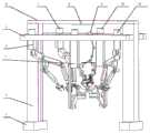
图1为全膝关节置换手术辅助机器人立体示意图;Fig. 1 is a three-dimensional schematic diagram of an auxiliary robot for total knee replacement surgery;
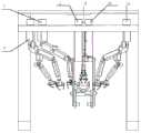
图2为全膝关节置换手术辅助机器人仰视图;Fig. 2 is the bottom view of the assistant robot for total knee replacement surgery;
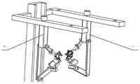
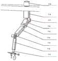
图3为全膝关节置换手术辅助机器人左视图;Fig. 3 is the left side view of the assistant robot for total knee replacement surgery;
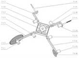
图4为大腿支撑夹紧机械臂与小腿支撑夹紧机械臂装配立体示意图;FIG. 4 is a schematic perspective view of the assembly of the thigh supporting and clamping manipulator and the calf supporting and clamping manipulator;
图5为大腿支撑夹紧机械臂立体示意图;5 is a three-dimensional schematic diagram of a thigh supporting and clamping robotic arm;
图6为大腿支撑夹紧机械臂主视图;Fig. 6 is the front view of the thigh support clamping mechanical arm;
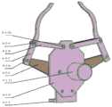
图7为大腿支撑夹紧机械臂的腿部夹压组件立体示意图1;7 is a
图8为大腿支撑夹紧机械臂的腿部夹压组件立体示意图2;FIG. 8 is a
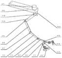
图9为左侧皮肤肌肉组织翻夹机械臂与右侧皮肤肌肉组织翻夹机械臂装配立体示意图;Fig. 9 is a schematic diagram showing the assembly of the left skin and muscle tissue flipping mechanical arm and the right skin and muscle tissue flipping mechanical arm;
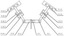
图10为皮肤肌肉组织翻夹机械臂的皮肤肌肉组织夹紧组件立体示意图1;Fig. 10 is the three-dimensional schematic diagram 1 of the skin and muscle tissue clamping assembly of the skin and muscle tissue flipping and clamping mechanical arm;
图11为皮肤肌肉组织翻夹机械臂的皮肤肌肉组织夹紧组件立体示意图2;Fig. 11 is the three-dimensional schematic diagram 2 of the skin-muscle tissue clamping assembly of the skin-muscle tissue flipping mechanical arm;
图12为手术机械臂立体示意图;Figure 12 is a three-dimensional schematic diagram of a surgical robotic arm;
图13为手术机械臂的手术末端组件立体示意图1;Fig. 13 is a three-dimensional schematic diagram 1 of the surgical end assembly of the surgical robotic arm;
图14为手术机械臂的手术末端组件立体示意图2;FIG. 14 is a
图15为立体视觉与光源机械臂立体示意图;Figure 15 is a three-dimensional schematic diagram of a stereo vision and light source robotic arm;
图16为立体视觉与光源机械臂的双目视觉移动光源组件示意图。FIG. 16 is a schematic diagram of the binocular vision moving light source assembly of the stereo vision and light source manipulator.
其中:1.支架底座;2.支架立柱;3.小腿支撑夹紧机械臂;4.左侧皮肤肌肉组织翻夹机械臂;5.支架连接板;6.支架盖板;7.手术机械臂;8.顶灯;9.立体视觉与光源机械臂;10.大腿支撑夹紧机械臂;11.右侧皮肤肌肉组织翻夹机械臂;Among them: 1. Bracket base; 2. Bracket column; 3. Calf support and clamping robot arm; 4. Left skin and muscle tissue flipping and clamping robot arm; 5. Bracket connecting plate; 8. Dome light; 9. Stereo vision and light source robotic arm; 10. Thigh support and clamping robotic arm; 11. Right skin and muscle tissue flipping and clamping robotic arm;
3-1.第一腿部方向舵机;3-2.第一腿部支撑连杆;3-3.第二腿部支撑连杆;3-4.腿部支撑转接杆;3-5.第二腿部方向舵机;3-6.腿部支撑槽;3-7.腿部夹压组件;3-8.夹压组件推动电缸;3-9.夹压组件电缸联接杆;3-10.腿部支撑联接螺钉;3-11.腿骨夹压组件方向舵机;3-12.腿部立柱;3-13.腿部支撑夹紧机械臂方向舵机;3-1. The steering gear of the first leg; 3-2. The first leg support link; 3-3. The second leg support link; 3-4. The leg support adapter rod; 3-5. The second leg steering gear; 3-6. Leg support groove; 3-7. Leg crimping assembly; 3-8. Clamping assembly push electric cylinder; 3-9. Clamping assembly electric cylinder connecting rod; 3 -10. Leg support connecting screw; 3-11. Leg bone clamping component steering gear; 3-12. Leg column; 3-13. Leg support clamping robotic arm steering gear;
3-7-1.第一腿骨夹紧末端;3-7-2.第一腿骨夹紧连接杆;3-7-3.第一腿骨夹紧连接销钉;3-7-4.腿骨压紧电缸;3-7-5.第二腿骨夹紧连接销钉;3-7-6.第一双目视觉摄像头;3-7-7.第一双目视觉摄像头转接板;3-7-8.第一双目视觉摄像头连接螺钉;3-7-9.第一移动光源;3-7-10.第一移动光源转接板;3-7-11.第一移动光源连接螺钉;3-7-12.第一移动光源旋转舵机;3-7-13.第一双目视觉移动光源组件连接螺钉;3-7-14.第一双目视觉移动光源组件连接板;3-7-15.第一双目视觉移动光源组件转接板;3-7-16.腿骨压紧电缸旋转舵机;3-7-17.腿骨压紧与双目视觉组件旋转舵机;3-7-18.腿骨夹压组件转接板;3-7-19.腿骨夹紧组件转接板;3-7-20.腿骨夹紧组件连接螺钉;3-7-21.腿骨夹紧舵机;3-7-22.腿骨夹紧齿轮连杆;3-7-23.第二腿骨夹紧连接销钉;3-7-24.第三腿骨夹紧连接销钉;3-7-25.第二腿骨夹紧连接杆;3-7-26.第四腿骨夹紧连接销钉;3-7-27.腿骨夹紧底座;3-7-28.第二腿骨夹紧末端;3-7-29.腿骨压紧末端;3-7-30.腿骨压紧电缸连接板;3-7-31.第五腿骨夹紧连接销钉;3-7-32.第一腿骨夹紧齿轮杆;3-7-33.第二腿骨夹紧齿轮杆;3-7-34.第一双目视觉移动光源组件转接板;3-7-1. The first leg bone clamping end; 3-7-2. The first leg bone clamping connecting rod; 3-7-3. The first leg bone clamping connecting pin; 3-7-4. Leg bone pressing electric cylinder; 3-7-5. The second leg bone clamping connecting pin; 3-7-6. The first binocular vision camera; 3-7-7. The first binocular vision camera adapter plate ; 3-7-8. The first binocular vision camera connecting screw; 3-7-9. The first moving light source; 3-7-10. The first moving light source adapter plate; 3-7-11. The first moving Light source connecting screw; 3-7-12. The first moving light source rotating servo; 3-7-13. The first binocular vision moving light source assembly connecting screw; 3-7-14. The first binocular vision moving light source assembly connection Board; 3-7-15. The first binocular vision moving light source assembly adapter board; 3-7-16. Leg bone compression electric cylinder rotary servo; 3-7-17. Leg bone compression and binocular vision Component Rotary Servo; 3-7-18. Legbone Clamping Assembly Adapter Plate; 3-7-19. Legbone Clamping Assembly Adapter Plate; 3-7-20. Legbone Clamping Assembly Connecting Screws; 3 -7-21. Legbone clamping servo; 3-7-22. Legbone clamping gear link; 3-7-23. Second legbone clamping connecting pin; 3-7-24. Third leg Bone clamping connecting pin; 3-7-25. Second leg bone clamping connecting rod; 3-7-26. Fourth leg bone clamping connecting pin; 3-7-27. Leg bone clamping base; 3- 7-28. The second leg bone clamping end; 3-7-29. The leg bone clamping end; 3-7-30. The leg bone clamping electric cylinder connecting plate; 3-7-31. The fifth leg bone clamp Tighten the connecting pin; 3-7-32. The first leg bone clamping gear rod; 3-7-33. The second leg bone clamping gear rod; 3-7-34. The first binocular vision mobile light source assembly transfer plate;
4-1.第一皮肤肌肉组织夹紧组件;4-2.第一皮肤肌肉组织夹紧组件旋转舵机;4-3.第二皮肤肌肉组织夹紧组件;4-4.第二皮肤肌肉组织夹紧组件旋转舵机;4-5.第二皮肤肌肉组织夹紧组件连杆;4-6.第一皮肤肌肉组织夹紧组件连杆;4-7.第一皮肤肌肉组织翻夹机臂舵机;4-8.第二皮肤肌肉组织翻夹机臂舵机;4-9.第一皮肤肌肉组织翻夹机臂连杆;4-10.第二皮肤肌肉组织翻夹机臂连杆;4-11.第三皮肤肌肉组织翻夹机臂舵机;4-12.第三皮肤肌肉组织翻夹机臂连杆;4-13.第四皮肤肌肉组织翻夹机臂舵机;4-14.第四皮肤肌肉组织翻夹机臂连杆;4-15.第五皮肤肌肉组织翻夹机臂舵机;4-1. The first skin and muscle tissue clamping assembly; 4-2. The first skin and muscle tissue clamping assembly rotary servo; 4-3. The second skin and muscle tissue clamping assembly; 4-4. The second skin and muscle tissue Tissue clamping assembly rotating steering gear; 4-5. Second skin and muscle tissue clamping assembly connecting rod; 4-6. First skin and muscle tissue clamping assembly connecting rod; 4-7. First skin and muscle tissue flipping machine Arm servo; 4-8. Arm servo of the second skin and muscle tissue flipping machine; 4-9. The first skin and muscle tissue flipping machine arm connecting rod; 4-10. The second skin and muscle tissue flipping machine arm connection Rod; 4-11. The third skin and muscle tissue flipping arm servo; 4-12. The third skin and muscle tissue flipping arm connecting rod; 4-13. The fourth skin and muscle tissue flipping arm servo; 4-14. The fourth skin and muscle tissue turning arm connecting rod; 4-15. The fifth skin and muscle tissue turning arm steering gear;
11-1.第三皮肤肌肉组织夹紧组件;11-2.第三皮肤肌肉组织夹紧组件旋转舵机;11-3.第四皮肤肌肉组织夹紧组件;11-4.第四皮肤肌肉组织夹紧组件旋转舵机;11-5.第三皮肤肌肉组织夹紧组件连杆;11-6.第四皮肤肌肉组织夹紧组件连杆;11-7.第六皮肤肌肉组织翻夹机臂舵机;11-8.第七皮肤肌肉组织翻夹机臂舵机;11-9.第五皮肤肌肉组织翻夹机臂连杆;11-10.第六皮肤肌肉组织翻夹机臂连杆;11-11.第八皮肤肌肉组织翻夹机臂舵机;11-12.第七皮肤肌肉组织翻夹机臂连杆;11-13.第九皮肤肌肉组织翻夹机臂舵机;11-14.第八皮肤肌肉组织翻夹机臂连杆;11-15.第十皮肤肌肉组织翻夹机臂舵机;11-1. The third skin and muscle tissue clamping assembly; 11-2. The third skin and muscle tissue clamping assembly rotary servo; 11-3. The fourth skin and muscle tissue clamping assembly; 11-4. The fourth skin and muscle tissue Tissue clamping assembly rotating steering gear; 11-5. The third skin and muscle tissue clamping assembly connecting rod; 11-6. The fourth skin and muscle tissue clamping assembly connecting rod; 11-7. The sixth skin and muscle tissue flipping machine Arm servo; 11-8. The seventh skin and muscle tissue flipping machine arm servo; 11-9. The fifth skin and muscle tissue flipping machine arm connecting rod; 11-10. The sixth skin and muscle tissue flipping machine arm connection Rod; 11-11. The eighth skin and muscle tissue flipping machine arm steering gear; 11-12. The seventh skin and muscle tissue flipping machine arm connecting rod; 11-13. The ninth skin and muscle tissue flipping machine arm steering gear; 11-14. The eighth skin and muscle tissue flipping arm connecting rod; 11-15. The tenth skin and muscle tissue flipping machine arm steering gear;
4-1-1.第一皮肤肌肉组织夹紧组件转接板;4-1-2.第一皮肤肌肉组织夹紧组件连接螺钉;4-1-3.第一皮肤肌肉组织夹紧组件底板;4-1-4.第一连接销钉;4-1-5.第一皮肤肌肉组织夹紧组件齿轮连杆;4-1-6.第二连接销钉;4-1-7.第一皮肤肌肉组织夹紧组件末端;4-1-8.第一连接板;4-1-9.第三连接销钉;4-1-10.第四连接销钉;4-1-11.第一皮肤肌肉组织夹紧组件夹紧舵机;4-1-1. The first skin and muscle tissue clamping assembly adapter plate; 4-1-2. The first skin and muscle tissue clamping assembly connecting screws; 4-1-3. The first skin and muscle tissue clamping assembly bottom plate 4-1-4. The first connecting pin; 4-1-5. The first skin muscle tissue clamping assembly gear link; 4-1-6. The second connecting pin; 4-1-7. The first skin Muscle tissue clamping assembly end; 4-1-8. The first connecting plate; 4-1-9. The third connecting pin; 4-1-10. The fourth connecting pin; 4-1-11. The first skin muscle Tissue clamping component clamping servo;
7-1.手术末端组件;7-2.第一手术机械臂连杆;7-3.第一手术机械臂舵机;7-4.第二手术机械臂连杆;7-5.第二手术机械臂舵机;7-6.第三手术机械臂连杆;7-7.第三手术机械臂舵机;7-8.第四手术机械臂连杆;7-9.手术机械臂组件转向舵机;7-1. Surgical end components; 7-2. The first surgical manipulator link; 7-3. The first surgical manipulator steering gear; 7-4. The second surgical manipulator link; 7-5. The second Surgical robotic arm steering gear; 7-6. The third surgical robotic arm connecting rod; 7-7. The third surgical robotic arm steering gear; 7-8. The fourth surgical robotic arm link; 7-9. Surgical robotic arm components steering gear;
7-1-1.腿骨切割驱动舵机;7-1-2.腿骨切割锯刀;7-1-3.腿骨切割连接板;7-1-4.腿骨切割部件转向舵机;7-1-5.手术末端组件底座;7-1-6.止血电刀部件转向舵机;7-1-7.止血电刀连接板;7-1-8.止血电刀;7-1-9.腿骨钻孔部件转向舵机;7-1-10.腿骨钻孔连接板;7-1-11.腿骨钻孔钻头;7-1-12.腿骨钻孔驱动舵机;7-1-13.皮肤切割部件转向舵机;7-1-14.皮肤切割连接板;7-1-15.皮肤切割驱动舵机;7-1-16.皮肤切割锯刀;7-1-17.手术末端组件转向舵机;7-1-1. Leg bone cutting drive servo; 7-1-2. Leg bone cutting saw blade; 7-1-3. Leg bone cutting connecting plate; 7-1-4. Leg bone cutting part steering servo ; 7-1-5. Surgical end assembly base; 7-1-6. Steering gear for hemostatic electrosurgery components; 7-1-7. Hemostatic electrosurgical connection plate; 7-1-8. Hemostatic electrosurgical knife; 7- 1-9. Leg bone drilling parts steering gear; 7-1-10. Leg bone drilling connection plate; 7-1-11. Leg bone drilling drill bit; 7-1-12. Leg bone drilling driving rudder 7-1-13. Skin cutting part steering servo; 7-1-14. Skin cutting connecting plate; 7-1-15. Skin cutting driving servo; 7-1-16. Skin cutting saw blade; 7 -1-17. Surgical end assembly steering servo;
9-1.第二双目视觉移动光源组件;9-2.第二双目视觉光源组件旋转舵机;9-3.第一立体视觉光源机臂舵机;9-4.第一立体视觉光源机臂连杆;9-5.第二体视觉光源机臂舵机;9-6.第二立体视觉光源机臂连杆;9-7.第三体视觉光源机臂舵机;9-8.第三立体视觉光源机臂连杆;9-9.第四体视觉光源机臂舵机;9-10.第四立体视觉光源机臂连杆;9-11.第五体视觉光源机臂舵机;9-12.立体视觉光源机臂连接板;9-13.第六立体视觉光源机臂舵机;9-14.第一立体视觉光源机臂转接板;9-15.第三双目视觉光源组件旋转舵机;9-16.第三双目视觉移动光源组;9-17.第二立体视觉光源机臂转接板;9-1. The second binocular vision moving light source assembly; 9-2. The second binocular vision light source assembly rotary steering gear; 9-3. The first stereo vision light source arm steering gear; 9-4. The first stereo vision Light source arm connecting rod; 9-5. Second stereo vision light source arm servo; 9-6. Second stereo vision light source arm connecting rod; 9-7. Third stereo vision light source arm servo; 9- 8. The third stereo vision light source arm connecting rod; 9-9. The fourth stereo vision light source arm steering gear; 9-10. The fourth stereo vision light source arm connecting rod; 9-11. The fifth body vision light source machine Arm servo; 9-12. Stereo vision light source arm connecting plate; 9-13. Sixth stereo vision light source arm servo; 9-14. First stereo vision light source arm adapter plate; 9-15. Section 9-15. Three binocular vision light source assembly rotary servo; 9-16. The third binocular vision moving light source group; 9-17. The second stereo vision light source arm adapter plate;
9-1-1.第二双目视觉移动光源组连接板;9-1-2.第二移动光源连接板;9-1-3.第二移动光源;9-1-4.第二双目视觉摄像头连接板;9-1-5.第二双目视觉摄像头;9-16-1.第三双目视觉移动光源组连接板;9-16-2.第三移动光源连接板;9-16-3.第三移动光源;9-16-4.第三双目视觉摄像头连接板;9-16-5.第三双目视觉摄像头。9-1-1. The second binocular vision moving light source group connecting plate; 9-1-2. The second moving light source connecting plate; 9-1-3. The second moving light source; 9-1-4. The second double Eye vision camera connecting board; 9-1-5. Second binocular vision camera; 9-16-1. Third binocular vision moving light source group connecting board; 9-16-2. Third moving light source connecting board; 9 -16-3. The third moving light source; 9-16-4. The third binocular vision camera connection board; 9-16-5. The third binocular vision camera.
具体实施方式Detailed ways
在本发明的描述中,需要理解的是,术语“中心”、“纵向”、“横向”、“上”、“下”、“前”、“后”、“左”、“右”、“竖直”、“水平”、“顶”、“底”、“内”、“外”、“一侧”、“一端”、“一边”等指示的方位或位置关系为基于附图所示的方位或位置关系,仅是为了便于描述本发明和简化描述,而不是指示或暗示所指的装置或元件必须具有特定的方位、以特定的方位构造和操作,因此不能理解为对本发明的限制。此外,术语“第一”、“第二”仅用于描述目的,而不能理解为指示或暗示相对重要性或者隐含指明所指示的技术特征的数量。由此,限定有“第一”、“第二”的特征可以明示或者隐含地包括一个或者更多个该特征。在本发明的描述中,除非另有说明,“多个”的含义是两个或两个以上。In the description of the present invention, it should be understood that the terms "center", "portrait", "horizontal", "top", "bottom", "front", "rear", "left", "right", " The orientation or positional relationship indicated by "vertical", "horizontal", "top", "bottom", "inside", "outside", "one side", "one end", "one side", etc. The orientation or positional relationship is only for the convenience of describing the present invention and simplifying the description, rather than indicating or implying that the indicated device or element must have a specific orientation, be constructed and operated in a specific orientation, and therefore should not be construed as a limitation of the present invention. In addition, the terms "first" and "second" are only used for descriptive purposes, and should not be construed as indicating or implying relative importance or implying the number of indicated technical features. Thus, a feature defined as "first" or "second" may expressly or implicitly include one or more of that feature. In the description of the present invention, unless otherwise specified, "plurality" means two or more.
在本发明的描述中,需要说明的是,除非另有明确的规定和限定,术语“安装”、“相连”、“连接”应做广义理解,例如,可以是固定连接,也可以是可拆卸连接,或一体地连接;可以是机械连接,也可以是电连接;可以是直接相连,也可以通过中间媒介间接相连,可以是两个元件内部的连通。对于本领域的普通技术人员而言,可以具体情况理解上述术语在本发明中的具体含义。In the description of the present invention, it should be noted that the terms "installed", "connected" and "connected" should be understood in a broad sense, unless otherwise expressly specified and limited, for example, it may be a fixed connection or a detachable connection Connection, or integral connection; can be mechanical connection, can also be electrical connection; can be directly connected, can also be indirectly connected through an intermediate medium, can be internal communication between two elements. For those of ordinary skill in the art, the specific meanings of the above terms in the present invention can be understood in specific situations.
本发明提供了一种全膝关节置换手术辅助机器人,设计了2只具有7个关节的切口皮肤肌肉组织翻夹机械手(左侧皮肤肌肉组织翻夹机械臂4和右侧皮肤肌肉组织翻夹机械臂11),实现了切口处皮肤肌肉组织的打开,为后续手术提供保障;设计了7个关节的手术手臂(手术机械臂7),实现了全膝关节置换手术中的皮肤切开、膝盖骨立体切削造型、膝盖骨连接处钻孔、手术中电刀止血的功能;设计了2条具有支撑和夹持定位组件的机械臂(小腿支撑夹紧机械臂3和大腿支撑夹紧机械臂10),实现了手术大腿与小腿的固定,为手术的精确性提供保证;设计了7个关节的具有双目摄像头及补充光源组件的机械臂(立体视觉与光源机械臂9),实现了手术中的视觉精确识别,保证了手术的准确高效。The present invention provides an auxiliary robot for total knee replacement surgery. Two incision skin and muscle tissue flipping robots with 7 joints (left skin and muscle tissue flipping
请参阅图1至图3,本发明一种全膝关节置换手术辅助机器人,包括支架底座1、支架立柱2、小腿支撑夹紧机械臂3、左侧皮肤肌肉组织翻夹机械臂4、支架连接板5、支架盖板6、手术机械臂7、顶灯8、立体视觉与光源机械臂9、大腿支撑夹紧机械臂10、右侧皮肤肌肉组织翻夹机械臂11。支架底座1在最下方,支架立柱2在支架底座1上方,支架盖板6在支架立柱2顶端,顶灯8在支架盖板6中间下方,支架连接板5固结在立柱侧面上部侧面,机械臂机构通过支架连接板5分布在支架立柱2两侧,一侧依次为左侧皮肤肌肉组织翻夹机械臂4、大腿支撑夹紧机械臂10、右侧皮肤肌肉组织翻夹机械臂11;另一侧依次为手术机械臂7、立体视觉与光源机械臂9、小腿支撑夹紧机械臂3。Please refer to FIG. 1 to FIG. 3 , an auxiliary robot for total knee replacement surgery according to the present invention includes a
请参阅图4至图8,腿部支撑夹紧机械臂包括对称设置的大腿支撑夹紧机械臂10和小腿支撑夹紧机械臂3,大腿支撑夹紧机械臂10和小腿支撑夹紧机械臂3的结构相同,其中,小腿支撑夹紧机械臂3包括第一腿部方向舵机的3-1、第一腿部支撑连杆的3-2、第二腿部支撑连杆的3-3、腿部支撑转接杆3-4、第二腿部方向舵机的3-5、腿部支撑槽3-6、腿部夹压组件3-7、夹压组件推动电缸3-8、夹压组件电缸联接杆3-9、腿部支撑联接螺钉3-10、腿骨夹压组件方向舵机3-11、腿部立柱3-12、腿部支撑夹紧机械臂方向舵机3-13。腿部支撑槽3-6用来支撑腿部下表面,腿部夹压组件3-7可以实现腿骨的两侧夹紧与上侧压紧,从而实现膝盖固定。Please refer to Fig. 4 to Fig. 8 , the leg supporting and clamping manipulator includes symmetrically arranged thigh supporting and clamping
第一腿部方向舵机3-1上端通过螺钉与腿部立柱3-12侧面连接,另一端与第二腿部支撑连杆3-3成角度连接,第二腿部支撑连杆3-3的末端通过第二腿部方向舵机3-5与腿部支撑转接杆3-4侧面连接,腿部支撑转接杆3-4的顶端与腿部支撑槽3-6的底端连接;The upper end of the steering gear 3-1 of the first leg is connected to the side of the leg column 3-12 through screws, and the other end is connected to the second leg support link 3-3 at an angle. The end is connected with the side of the leg support adapter rod 3-4 through the second leg steering gear 3-5, and the top end of the leg support adapter rod 3-4 is connected with the bottom end of the leg support groove 3-6;
腿部夹压机构包括夹压组件电缸联接杆3-9,夹压组件电缸联接杆3-9的一端通过腿骨夹压组件方向舵机3-11与腿部立柱3-12侧边连接,另一端连接夹压组件推动电缸3-8的底部,夹压组件推动电缸3-8的顶部与腿骨夹压组件连接。The leg clamping mechanism includes the electric cylinder connecting rod 3-9 of the clamping assembly, and one end of the electric cylinder connecting rod 3-9 of the clamping assembly is connected to the side of the leg column 3-12 through the rudder gear 3-11 of the leg bone clamping assembly , the other end is connected to the crimping component to push the bottom of the electric cylinder 3-8, and the crimping component pushes the top of the electric cylinder 3-8 to connect with the leg bone crimping component.
腿骨夹压组件包括腿骨夹压组件转接板3-7-18,腿骨夹压组件转接板3-7-18一侧中心与夹压组件推动电缸3-8顶部连接,另一侧上部通过腿骨压紧与双目视觉组件旋转舵机3-7-17与腿骨夹紧组件连接;The leg bone crimping assembly includes the leg bone crimping assembly adapter plate 3-7-18. The center of one side of the leg bone crimping assembly adapter plate 3-7-18 is connected to the top of the crimping assembly pushing electric cylinder 3-8, and the other The upper part of one side is connected with the leg bone clamping assembly through the leg bone compression and the binocular vision assembly rotary servo 3-7-17;
腿骨夹压组件转接板3-7-18的另一侧下部通过螺钉与腿骨夹紧组件转接板3-7-19垂直侧面连接,腿骨夹紧组件转接板3-7-19水平侧通过腿骨夹紧组件连接螺钉3-7-20与腿骨夹紧底座3-7-27相连;The lower part of the other side of the leg bone clamping assembly adapter plate 3-7-18 is connected to the vertical side of the leg bone clamping assembly adapter plate 3-7-19 through screws, and the leg bone clamping assembly adapter plate 3-7- 19 The horizontal side is connected with the leg bone clamping base 3-7-27 through the leg bone clamping assembly connecting screw 3-7-20;
腿骨夹紧底座3-7-27通过腿骨夹紧舵机3-7-21与第一腿骨夹紧齿轮杆3-7-32和第二腿骨夹紧齿轮杆3-7-33连接,第一腿骨夹紧齿轮杆3-7-32和第二腿骨夹紧齿轮杆3-7-33对称设置,连接关系相同,分别连接对应的第一腿骨夹紧末端3-7-1和第二腿骨夹紧末端3-7-28,第一腿骨夹紧齿轮杆3-7-32和第二腿骨夹紧齿轮杆3-7-33的连接关系相同,这里以第二腿骨夹紧齿轮杆3-7-33的连接关系进行说明,第二腿骨夹紧齿轮杆3-7-33另一端通过第二腿骨夹紧连接销钉3-7-23与第二腿骨夹紧末端3-7-28的一端连接,第二腿骨夹紧末端3-7-28的中部通过第三腿骨夹紧连接销钉3-7-24与第二腿骨夹紧连接杆3-7-25连接,第二腿骨夹紧连接杆3-7-25通过第四腿骨夹紧连接销钉3-7-26与腿骨夹紧底座3-7-27上侧连接;Legbone clamping base 3-7-27 through legbone clamping servo 3-7-21 and first legbone clamping gear rod 3-7-32 and second legbone clamping gear rod 3-7-33 Connection, the first leg bone clamping gear rod 3-7-32 and the second leg bone clamping gear rod 3-7-33 are symmetrically arranged, the connection relationship is the same, and the corresponding first leg bone clamping ends 3-7 are respectively connected -1 and the second leg bone clamping end 3-7-28, the connection relationship between the first leg bone clamping gear rod 3-7-32 and the second leg bone clamping gear rod 3-7-33 is the same, here The connection relationship of the second leg bone clamping gear rod 3-7-33 is described. The other end of the second leg bone clamping gear rod 3-7-33 is connected to the second leg bone clamping connecting pin 3-7-23 with the One end of the second legbone clamping end 3-7-28 is connected, and the middle part of the second legbone clamping end 3-7-28 is clamped with the second legbone through the third legbone clamping connecting pin 3-7-24 The connecting rod 3-7-25 is connected, the second leg bone clamping connecting rod 3-7-25 is connected to the upper side of the leg bone clamping base 3-7-27 through the fourth leg bone clamping connecting pin 3-7-26 ;
腿骨夹紧组件包括腿骨压紧电缸连接板3-7-30,腿骨压紧电缸连接板3-7-30一端通过腿骨压紧与双目视觉组件旋转舵机3-7-17与腿骨夹压组件转接板3-7-18连接,中间通过腿骨压紧电缸旋转舵机3-7-16与腿骨压紧电缸3-7-4联接,另一端通过第一移动光源旋转舵机3-7-12与双目视觉移动光源组件连接,腿骨压紧电缸3-7-4的另一端连接腿骨压紧末端3-7-29;The leg bone clamping assembly includes the leg bone pressing electric cylinder connecting plate 3-7-30, and one end of the leg bone pressing electric cylinder connecting plate 3-7-30 rotates the steering gear through the leg bone pressing and binocular vision assembly 3-7 -17 is connected to the adapter plate 3-7-18 of the leg bone clamping assembly, the middle is connected to the leg bone compression cylinder 3-7-4 through the leg bone compression electric cylinder rotating servo 3-7-16, and the other end The first moving light source rotating servo 3-7-12 is connected to the binocular vision moving light source assembly, and the other end of the leg bone pressing electric cylinder 3-7-4 is connected to the leg bone pressing end 3-7-29;
双目视觉移动光源组件包括第一双目视觉移动光源组件转接板3-7-34,第一双目视觉移动光源组件转接板3-7-34侧面通过第一移动光源旋转舵机3-7-12与腿骨压紧电缸连接板3-7-30连接;上侧通过第一双目视觉移动光源组件连接螺钉3-7-13与第一双目视觉移动光源组件连接板3-7-14后端连接,第一双目视觉移动光源组件连接板3-7-14中间通过第一移动光源连接螺钉3-7-11与第一移动光源3-7-9连接,第一双目视觉移动光源组件连接板3-7-14前端通过第一双目视觉摄像头连接螺钉3-7-8与第一双目视觉摄像头3-7-6连接。The binocular vision moving light source assembly includes a first binocular vision moving light source assembly adapter plate 3-7-34, and the side of the first binocular vision moving light source assembly adapter plate 3-7-34 rotates the
请参阅图9至图11,皮肤肌肉组织翻夹机械臂机构包括左右两侧对称设置的两个机械臂,两个机械臂的结构相同,其中一侧的皮肤肌肉组织翻夹机械臂机构包括第一皮肤肌肉组织夹紧组件的4-1、第一皮肤肌肉组织夹紧组件旋转舵机4-2、第二皮肤肌肉组织夹紧组件的4-3、第二皮肤肌肉组织夹紧组件旋转舵机4-4、第二皮肤肌肉组织夹紧组件连杆4-5、第一皮肤肌肉组织夹紧组件连杆4-6、第一皮肤肌肉组织翻夹机臂舵机的4-7、第二皮肤肌肉组织翻夹机臂舵机的4-8、第一皮肤肌肉组织翻夹机臂连杆的4-9、第二皮肤肌肉组织翻夹机臂连杆的4-10、第三皮肤肌肉组织翻夹机臂舵机的4-11、第三皮肤肌肉组织翻夹机臂连杆的4-12、第四皮肤肌肉组织翻夹机臂舵机的4-13、第四皮肤肌肉组织翻夹机臂连杆的4-14、第五皮肤肌肉组织翻夹机臂舵机的4-15。Please refer to Fig. 9 to Fig. 11. The mechanical arm mechanism for flipping and clipping skin and muscle tissue includes two mechanical arms symmetrically arranged on the left and right sides. The structures of the two mechanical arms are the same. 1. 4-1 of the skin and muscle tissue clamping assembly, 4-2 of the first skin and muscle tissue clamping assembly rotary steering gear, 4-3 of the second skin and muscle tissue clamping assembly, 4-3 of the second skin and muscle tissue clamping assembly rotating rudder Machine 4-4, second skin and muscle tissue clamping assembly connecting rod 4-5, first skin and muscle tissue clamping assembly connecting rod 4-6, first skin and muscle tissue flipping machine arm steering gear 4-7, the first 4-8 of the second skin and musculature turning arm steering gear, 4-9 of the first skin and musculature turning arm connecting rod, 4-10 of the second skin and musculature turning arm connecting rod, third skin and musculature 4-11 of the musculature flipper arm servo, 4-12 of the third skin musculature flipper arm connecting rod, 4-13 of the fourth skin musculature flipper arm steering gear, fourth skin musculature 4-14 of the connecting rod of the flipper arm, 4-15 of the steering gear of the fifth skin and muscle tissue flipper arm.
第四皮肤肌肉组织翻夹机臂连杆4-14的上端通过第五皮肤肌肉组织翻夹机臂舵机4-15与支架连接板5连接,下端通过第四皮肤肌肉组织翻夹机臂舵机4-13与第三皮肤肌肉组织翻夹机臂连杆4-12的后端连接,第三皮肤肌肉组织翻夹机臂连杆4-12的前端通过第三皮肤肌肉组织翻夹机臂舵机4-11与第二皮肤肌肉组织翻夹机臂连杆4-10的后端连接,第二皮肤肌肉组织翻夹机臂连杆4-10的前端通过第二皮肤肌肉组织翻夹机臂舵机4-8与第一皮肤肌肉组织夹紧组件连杆4-6的后端连接,第一皮肤肌肉组织夹紧组件连杆4-6的前端与第一皮肤肌肉组织夹紧组件旋转舵机4-2连接,第一皮肤肌肉组织夹紧组件旋转舵机4-2输出端与第一皮肤肌肉组织夹紧组件4-1连接;第二皮肤肌肉组织翻夹机臂连杆4-10下侧中部与第一皮肤肌肉组织翻夹机臂连杆4-9的上端连接,第一皮肤肌肉组织翻夹机臂连杆4-9的底端通过第一皮肤肌肉组织翻夹机臂舵机4-7与第二皮肤肌肉组织夹紧组件连杆4-5的后端连接,第二皮肤肌肉组织夹紧组件连杆4-5的前端与第二皮肤肌肉组织夹紧组件旋转舵机4-4连接,第二皮肤肌肉组织夹紧组件旋转舵机4-4的输出端与第二皮肤肌肉组织夹紧组件4-3连接。The upper end of the fourth skin and muscle tissue turning arm connecting rod 4-14 is connected to the bracket connecting plate 5 through the fifth skin and muscle tissue turning arm steering gear 4-15, and the lower end passes through the fourth skin and muscle tissue turning arm rudder The machine 4-13 is connected with the rear end of the third skin and muscle tissue flipping machine arm link 4-12, and the front end of the third skin and muscle tissue flipping machine arm link 4-12 passes through the third skin and muscle tissue flipping machine arm The steering gear 4-11 is connected with the rear end of the second skin and muscle tissue turning arm link 4-10, and the front end of the second skin and muscle tissue turning arm connecting rod 4-10 passes through the second skin and muscle tissue turning machine The arm steering gear 4-8 is connected with the rear end of the first skin and muscle tissue clamping component link 4-6, and the front end of the first skin and muscle tissue clamping component link 4-6 rotates with the first skin and muscle tissue clamping component The steering gear 4-2 is connected, and the output end of the rotating steering gear 4-2 of the first skin and muscle tissue clamping component is connected with the first skin and muscle tissue clamping component 4-1; the second skin and muscle tissue is turned over by the arm connecting rod 4- 10 lower side middle part is connected with the upper end of the first skin and muscle tissue turning clip machine arm connecting rod 4-9, and the bottom end of the first skin muscle tissue turning clip machine arm connecting rod 4-9 passes through the first skin muscle tissue turning clip machine arm The steering gear 4-7 is connected with the rear end of the second skin and muscle tissue clamping component connecting rod 4-5, and the front end of the second skin and muscle tissue clamping component connecting rod 4-5 rotates the rudder with the second skin and muscle tissue clamping component The motor 4-4 is connected, and the output end of the rotary steering gear 4-4 of the second skin and muscle tissue clamping component is connected with the second skin and muscle tissue clamping component 4-3.
第一皮肤肌肉组织夹紧组件4-1包括第一皮肤肌肉组织夹紧组件转接板4-1-1,第一皮肤肌肉组织夹紧组件转接板4-1-1垂直侧面通过螺钉固定在第二皮肤肌肉组织夹紧组件旋转舵机4-4的输出端,转接板4-1-1水平侧通过第一皮肤肌肉组织夹紧组件连接螺钉4-1-2与第一皮肤肌肉组织夹紧组件底板4-1-3相连;第一皮肤肌肉组织夹紧组件底板4-1-3中部通过第一皮肤肌肉组织夹紧组件夹紧舵机4-1-11分别与对称设置的两个第一皮肤肌肉组织夹紧组件齿轮连杆4-1-5连接,两个第一皮肤肌肉组织夹紧组件齿轮连杆4-1-5直接通过齿轮啮合连接,两个第一皮肤肌肉组织夹紧组件齿轮连杆4-1-5另一端分别通过一个第二连接销钉4-1-6与对应的一个第一皮肤肌肉组织夹紧组件末端4-1-7的一端连接,第一皮肤肌肉组织夹紧组件末端4-1-7的中部通过第三连接销钉4-1-9与一个第一连接板4-1-8连接,第一连接板4-1-8通过第四连接销钉4-1-10与第一皮肤肌肉组织夹紧组件底板4-1-3上侧连接,从而构成连杆机构;第一皮肤肌肉组织夹紧组件底板4-1-3中部通过齿轮连杆与第一皮肤肌肉组织夹紧组件齿轮连杆4-1-5啮合。The first skin and muscle tissue clamping assembly 4-1 includes a first skin and muscle tissue clamping assembly adapter plate 4-1-1, and the vertical side of the first skin and muscle tissue clamping assembly adapter plate 4-1-1 is fixed by screws At the output end of the rotating steering gear 4-4 of the second skin and muscle tissue clamping assembly, the horizontal side of the adapter plate 4-1-1 connects the first skin and muscle tissue clamping assembly with the screw 4-1-2 and the first skin and muscle tissue at the horizontal side. The bottom plate 4-1-3 of the tissue clamping component is connected; the middle part of the bottom plate 4-1-3 of the first skin and muscle tissue clamping component is respectively connected with the symmetrically arranged steering gears 4-1-11 through the first skin and muscle tissue clamping component clamping steering gear 4-1-11. The gear links 4-1-5 of the two first skin and muscle tissue clamping assemblies are connected, and the gear links 4-1-5 of the two first skin and muscle tissue clamping assemblies are directly connected by gear meshing, and the two first skin muscle tissue The other ends of the gear connecting rods 4-1-5 of the tissue clamping assembly are respectively connected with one end of a corresponding end 4-1-7 of the first skin and muscle tissue clamping assembly through a second connecting pin 4-1-6. The middle part of the end 4-1-7 of the skin and muscle tissue clamping assembly is connected with a first connecting plate 4-1-8 through a third connecting pin 4-1-9, and the first connecting plate 4-1-8 is connected through a fourth connection The pin 4-1-10 is connected with the upper side of the base plate 4-1-3 of the first skin and muscle tissue clamping assembly, thereby forming a link mechanism; the middle part of the base plate 4-1-3 of the first skin and muscle tissue clamping assembly is connected by a gear link Engage with the first skin-muscle tissue clamping assembly gear link 4-1-5.
请参阅图12至图14,手术机械臂7包括手术末端组件7-1、第一手术机械臂连杆的7-2、第一手术机械臂舵机的7-3、第二手术机械臂连杆的7-4、第二手术机械臂舵机的7-5、第三手术机械臂连杆的7-6、第三手术机械臂舵机的7-7、第四手术机械臂连杆的7-8。连杆依次串联,最后为手术末端组件7-1。Please refer to FIG. 12 to FIG. 14 , the
第四手术机械臂连杆7-8上端通过方向舵机与支架连接板5连接,下端通过第三手术机械臂舵机7-7与第三手术机械臂连杆7-6的后端连接,第三手术机械臂连杆7-6前端通过第二手术机械臂舵机7-5与第二手术机械臂连杆7-4后端连接,第二手术机械臂连杆7-4的前端通过第一手术机械臂舵机7-3与第一手术机械臂连杆7-2的后端连接,第一手术机械臂连杆7-2的前端与手术末端组件7-1连接。The upper end of the fourth operating manipulator connecting rod 7-8 is connected to the
手术末端组件7-1包括手术末端组件转向舵机7-1-17,手术末端组件转向舵机7-1-17上端通过螺钉与第一手术机械臂连杆7-2的前端连接,手术末端组件转向舵机7-1-17输出端与手术末端组件底座7-1-5中心连接,手术末端组件底座7-1-5底座四个伸出端分别通过舵机与腿骨切割机构、皮肤切割机构、腿骨钻孔机构、止血电刀机构连接;The surgical end assembly 7-1 includes a steering servo 7-1-17 of the surgical end assembly. The upper end of the surgical end assembly steering servo 7-1-17 is connected to the front end of the first surgical mechanical arm link 7-2 through screws. The surgical end The output end of the steering gear 7-1-17 of the component is connected to the center of the base 7-1-5 of the surgical end assembly, and the four protruding ends of the base 7-1-5 of the surgical end assembly are connected to the leg bone cutting mechanism and the skin respectively through the steering gear. The cutting mechanism, the leg bone drilling mechanism, and the hemostatic electric knife mechanism are connected;
腿骨切割机构包括腿骨切割连接板7-1-3,腿骨切割连接板7-1-3一端通过腿骨切割部件转向舵机7-1-4与手术末端组件底座7-1-5连接,另一端通过腿骨切割驱动舵机7-1-1与腿骨切割锯刀7-1-2中心侧面连接;The leg bone cutting mechanism includes the leg bone cutting connecting plate 7-1-3, one end of the leg bone cutting connecting plate 7-1-3 is turned to the steering gear 7-1-4 through the leg bone cutting part and the operation end assembly base 7-1-5 Connect, the other end is connected to the central side of the leg bone cutting saw blade 7-1-2 through the leg bone cutting drive servo 7-1-1;
皮肤切割机构包括皮肤切割连接板7-1-14,皮肤切割连接板7-1-14一端通过皮肤切割部件转向舵机7-1-13与手术末端组件底座7-1-5连接,另一端通过皮肤切割驱动舵机7-1-15与皮肤切割锯刀7-1-16中心侧面连接;The skin cutting mechanism includes a skin cutting connecting plate 7-1-14. One end of the skin cutting connecting plate 7-1-14 is connected to the operating end assembly base 7-1-5 through the skin cutting component steering servo 7-1-13, and the other end is connected to the base 7-1-5 of the surgical end assembly. Through the skin cutting drive servo 7-1-15 is connected with the center side of the skin cutting saw blade 7-1-16;
腿骨钻孔机构包括腿骨钻孔连接板7-1-10,腿骨钻孔连接板7-1-10一端通过腿骨钻孔部件转向舵机7-1-9与手术末端组件底座7-1-5连接,另一端垂面通过腿骨钻孔驱动舵机7-1-12与腿骨钻孔钻头7-1-11的上端连接;The leg bone drilling mechanism includes the leg bone drilling connection plate 7-1-10, one end of the leg bone drilling connection plate 7-1-10 is turned through the leg bone drilling component steering servo 7-1-9 and the operation end assembly base 7 -1-5 is connected, and the other end of the vertical plane is connected with the upper end of the leg bone drilling bit 7-1-11 through the leg bone drilling drive steering gear 7-1-12;
止血电刀机构包括止血电刀连接板7-1-7,止血电刀连接板7-1-7一端通过止血电刀部件转向舵机7-1-6与手术末端组件底座7-1-5连接,另一端垂面与止血电刀7-1-8上端连接。The hemostatic electrosurgical mechanism includes a hemostatic electrosurgical connecting plate 7-1-7, one end of the hemostatic electrosurgical connecting plate 7-1-7 is turned to a steering gear 7-1-6 through the hemostasis electrosurgical unit and a base 7-1-5 of the surgical end assembly connected, and the other end of the vertical surface is connected to the upper end of the hemostatic electrosurgical knife 7-1-8.
请参阅图15至图16,立体视觉与光源机械臂9包括第二双目视觉移动光源组件的9-1、第二双目视觉光源组件旋转舵机9-2、第一立体视觉光源机臂舵机的9-3、第一立体视觉光源机臂连杆的9-4、第二体视觉光源机臂舵机的9-5、第二立体视觉光源机臂连杆的9-6、第三体视觉光源机臂舵机的9-7、第三立体视觉光源机臂连杆的9-8、第四体视觉光源机臂舵机的9-9、第四立体视觉光源机臂连杆的9-10、第五体视觉光源机臂舵机的9-11、立体视觉光源机臂连接板9-12、第六立体视觉光源机臂舵机的9-13、第一立体视觉光源机臂转接板的9-14、第三双目视觉光源组件旋转舵机9-15、第三双目视觉光源组件的9-16、第二立体视觉光源机臂转接板的9-17。连杆依次串联,最后为双目视觉移动光源组件。Please refer to FIG. 15 to FIG. 16 , the stereoscopic vision and light source mechanical arm 9 includes a second binocular vision moving light source assembly 9-1, a second binocular vision light source assembly rotating steering gear 9-2, and a first stereoscopic vision light source arm 9-3 of the steering gear, 9-4 of the arm connecting rod of the first stereo vision light source, 9-5 of the arm servo of the second stereo vision light source, 9-6 of the arm connecting rod of the second stereo vision light source, 9-7 of the arm servo of the three-body vision light source, 9-8 of the arm link of the third stereo vision light source, 9-9 of the arm servo of the fourth stereo vision light source, and arm link of the fourth stereo vision light source 9-10 of the fifth stereo vision light source arm servo, 9-11 of the stereo vision light source arm connecting plate, 9-13 of the sixth stereo vision light source arm servo, the first stereo vision light source 9-14 of the arm adapter plate, 9-15 of the rotating steering gear of the third binocular vision light source assembly, 9-16 of the third binocular vision light source assembly, and 9-17 of the second stereoscopic vision light source arm adapter plate. The connecting rods are connected in series, and finally the binocular vision moving light source assembly.
立体视觉光源机臂连接板9-12后端通过螺钉与支架连接板5连接,立体视觉光源机臂连接板9-12前端通过第六立体视觉光源机臂舵机9-13与第一立体视觉光源机臂转接板9-14上端连接,第一立体视觉光源机臂转接板9-14侧面通过第五体视觉光源机臂舵机9-11与第四立体视觉光源机臂连杆9-10上端连接,第四立体视觉光源机臂连杆9-10下端通过第四体视觉光源机臂舵机9-9与第三立体视觉光源机臂连杆9-8后端连接,第三立体视觉光源机臂连杆9-8前端通过第三体视觉光源机臂舵机9-7与第二立体视觉光源机臂连杆9-6后端连接,第二立体视觉光源机臂连杆9-6前端通过第二体视觉光源机臂舵机9-5与第一立体视觉光源机臂连杆9-4后端连接,第一立体视觉光源机臂连杆9-4前端通过第一立体视觉光源机臂舵机9-3与第二立体视觉光源机臂转接板9-17上端连接,第二立体视觉光源机臂转接板9-17下部两端通过舵机分别与第二双目视觉移动光源组9-1和第三双目视觉移动光源组9-16连接。The rear end of the stereo vision light source arm connecting plate 9-12 is connected to the bracket connecting plate 5 through screws, and the front end of the stereo vision light source arm connecting plate 9-12 is connected to the first stereo vision through the sixth stereo vision light source arm servo 9-13 The upper end of the light source arm adapter plate 9-14 is connected, and the side of the first stereo vision light source arm adapter plate 9-14 passes through the fifth stereo vision light source arm steering gear 9-11 and the fourth stereo vision light source arm connecting rod 9 The upper end of -10 is connected, and the lower end of the fourth stereo vision light source arm connecting rod 9-10 is connected to the rear end of the third stereo vision light source arm connecting rod 9-8 through the fourth stereo vision light source arm steering gear 9-9, and the third The front end of the arm link 9-8 of the stereo vision light source is connected to the rear end of the arm link 9-6 of the second stereo vision light source through the arm steering gear 9-7 of the third stereo vision light source, and the arm link of the second stereo vision light source is connected to the rear end of the second stereo vision light source arm link 9-6. The front end of 9-6 is connected with the rear end of the first stereo vision light source arm link 9-4 through the second stereo vision light source arm steering gear 9-5, and the front end of the first stereo vision light source arm link 9-4 passes through the first stereo vision light source arm link 9-4. Stereo vision light source arm steering gear 9-3 is connected with the upper end of the second stereo vision light source arm adapter plate 9-17, and the lower ends of the second stereo vision light source arm adapter plate 9-17 are respectively connected to the second stereo vision light source arm adapter plate 9-17 through the steering gear. The binocular vision moving light source group 9-1 is connected to the third binocular vision moving light source group 9-16.
第二双目视觉移动光源组9-1和第三双目视觉移动光源组9-16均包括第二双目视觉移动光源组连接板9-1-1,第二双目视觉移动光源组连接板9-1-1后端通过第二双目视觉光源组件旋转舵机9-2与第二立体视觉光源机臂转接板9-17一端连接,第二双目视觉移动光源组连接板9-1-1中间通过第二移动光源连接板9-1-2与第二移动光源9-1-3连接,第二双目视觉移动光源组连接板9-1-1前端通过第二双目视觉摄像头连接板9-1-4与第二双目视觉摄像头9-1-5连接。The second binocular vision moving light source group 9-1 and the third binocular vision moving light source group 9-16 both include a second binocular vision moving light source group connecting plate 9-1-1, and the second binocular vision moving light source group is connected The rear end of the board 9-1-1 is connected to one end of the second stereo vision light source arm adapter plate 9-17 through the second binocular vision light source assembly rotary steering gear 9-2, and the second binocular vision mobile light source group connecting plate 9 -1-1 is connected to the second moving light source 9-1-3 through the second moving light source connecting plate 9-1-2 in the middle, and the front end of the second binocular vision moving light source group connecting plate 9-1-1 passes through the second binocular The visual camera connecting board 9-1-4 is connected with the second binocular visual camera 9-1-5.
本发明的全膝关节置换手术辅助机器人,提高了手术的准确性、稳定性和效率,减轻了医生负担,具有广阔的市场前景,同时为其他手术机器人设计提供了借鉴作用,具有较高的科学研究价值。The auxiliary robot for total knee replacement surgery of the present invention improves the accuracy, stability and efficiency of surgery, reduces the burden on doctors, has broad market prospects, and provides reference for the design of other surgical robots, and has high scientific research value.
七个关节两组立体视觉与光源机械臂机构的设计提高了目标的快速准确识别,实现了膝关节手术的快速准确立体重构的功能。The design of the seven-joint two-group stereo vision and light source mechanical arm mechanism improves the fast and accurate identification of the target, and realizes the function of fast and accurate stereo reconstruction for knee surgery.
两条具有支撑和夹持定位组件的机械臂,实现了手术大腿与小腿的固定,从而固定了膝关节,为手术的精确性提供保证。Two mechanical arms with supporting and clamping positioning components realize the fixation of the thigh and calf in operation, thus fixing the knee joint and guaranteeing the accuracy of the operation.
两个皮肤肌肉组织翻夹机械臂,四个新型翻夹组件协同工作,实现了膝关节切口皮肤肌肉组织的微精确翻开,减少了手术切口翻开的二次创伤。Two skin and muscle tissue flipping robotic arms and four new flipping components work together to achieve micro-accurate flipping of the skin and muscle tissue of the knee joint incision, reducing the secondary trauma of surgical incision opening.
带有七个舵机手术机械臂机构实现了全膝关节置换手术的膝关节皮肤肌肉组织切口、切口止血、膝盖骨切削、膝盖骨钻孔等功能,并能实时实现功能切换,大大提高了手术的准确性、稳定性与效率。The mechanical arm mechanism with seven steering gears realizes the functions of knee skin and muscle tissue incision, incision hemostasis, patella cutting, and patella drilling for total knee replacement surgery, and can realize function switching in real time, which greatly improves the accuracy of surgery. performance, stability and efficiency.
为使本发明实施例的目的、技术方案和优点更加清楚,下面将结合本发明实施例中的附图,对本发明实施例中的技术方案进行清楚、完整地描述,显然,所描述的实施例是本发明一部分实施例,而不是全部的实施例。通常在此处附图中的描述和所示的本发明实施例的组件可以通过各种不同的配置来布置和设计。因此,以下对在附图中提供的本发明的实施例的详细描述并非旨在限制要求保护的本发明的范围,而是仅仅表示本发明的选定实施例。基于本发明中的实施例,本领域普通技术人员在没有作出创造性劳动前提下所获得的所有其他实施例,都属于本发明保护的范围。In order to make the purposes, technical solutions and advantages of the embodiments of the present invention clearer, the technical solutions in the embodiments of the present invention will be clearly and completely described below with reference to the accompanying drawings in the embodiments of the present invention. Obviously, the described embodiments These are some embodiments of the present invention, but not all embodiments. The components of the embodiments of the invention generally described and illustrated in the drawings herein may be arranged and designed in a variety of different configurations. Thus, the following detailed description of the embodiments of the invention provided in the accompanying drawings is not intended to limit the scope of the invention as claimed, but is merely representative of selected embodiments of the invention. Based on the embodiments of the present invention, all other embodiments obtained by those of ordinary skill in the art without creative efforts shall fall within the protection scope of the present invention.
本发明一种全膝关节置换手术机器人的基本运动模态包括腿部固定夹紧、皮肤肌肉组织翻夹和手术操作三种状态,具体工作原理如下:The basic motion mode of a total knee replacement surgical robot of the present invention includes three states: leg fixed and clamped, skin and muscle tissue flipped, and surgical operation. The specific working principle is as follows:
腿部固定夹紧:Leg fixed clamping:
将患者腿放置在腿部支撑槽3-6内,调整第一腿部方向舵机的3-1和第二腿部方向舵机的3-5,使得膝关节位置合理;调整腿骨夹压组件方向舵机3-11与夹压组件推动电缸3-8,使得组件与腿部相对位置合理;腿骨夹紧舵机3-7-21旋转,带动第一腿骨夹紧末端3-7-1与第二腿骨夹紧末端3-7-28夹紧腿骨两侧,同时调整腿骨压紧电缸旋转舵机3-7-16,使得腿骨压紧末端3-7-29位置合理,腿骨压紧电缸3-7-4工作,压紧腿骨,从而实现腿部固定。Place the patient's leg in the leg support groove 3-6, adjust 3-1 of the steering gear of the first leg and 3-5 of the steering gear of the second leg, so that the position of the knee joint is reasonable; adjust the rudder of the leg bone clamping assembly The motor 3-11 and the clamping component push the electric cylinder 3-8, so that the relative position of the component and the leg is reasonable; the leg bone clamping servo 3-7-21 rotates to drive the first leg bone clamping end 3-7-1 Clamp both sides of the leg bone with the second leg bone clamping end 3-7-28, and adjust the leg bone clamping electric cylinder to rotate the servo 3-7-16, so that the leg bone clamping end 3-7-29 is in a reasonable position , the leg bone pressing electric cylinder 3-7-4 works, pressing the leg bone, so as to achieve leg fixation.
皮肤肌肉组织翻夹:Skin and Muscle Tissue Clips:
两个腿部固定后,即固定了膝关节,膝关节处皮肤肌肉组织进行切口,然后调整皮肤肌肉组织夹紧机械臂的各关节舵机,使得第一皮肤肌肉组织夹紧组件4-1、第二皮肤肌肉组织夹紧组件4-3、第三皮肤肌肉组织夹紧组件11-1、第四皮肤肌肉组织夹紧组件11-3处在合适位置,第一皮肤肌肉组织夹紧组件夹紧舵机4-1-11、第二皮肤肌肉组织夹紧组件夹紧舵机、第三皮肤肌肉组织夹紧组件夹紧舵机、第四皮肤肌肉组织夹紧组件夹紧舵机工作,带动第一皮肤肌肉组织夹紧组件齿轮连杆4-1-5、第二皮肤肌肉组织夹紧组件齿轮连杆、第三皮肤肌肉组织夹紧组件齿轮连杆、第四皮肤肌肉组织夹紧组件齿轮连杆转动,实现第一皮肤肌肉组织夹紧组件末端4-1-7、第二皮肤肌肉组织夹紧组件末端、第三皮肤肌肉组织夹紧组件末端、第四皮肤肌肉组织夹紧组件末端的松开和夹紧,夹好后,调整机械臂各关节舵机,实现合理翻开的动作。After the two legs are fixed, the knee joint is fixed, the skin and muscle tissue at the knee joint is incised, and then each joint servo of the skin and muscle tissue is adjusted to clamp the mechanical arm, so that the first skin and muscle tissue clamping components 4-1, The second skin and muscle tissue clamping components 4-3, the third skin and muscle tissue clamping components 11-1, and the fourth skin and muscle tissue clamping components 11-3 are in proper positions, and the first skin and muscle tissue clamping components are clamped Servo 4-1-11, the second skin and muscle tissue clamping assembly clamps the servo, the third skin and muscle tissue clamping assembly clamps the servo, and the fourth skin and muscle tissue clamping assembly clamps the servo to work, driving the first A skin and muscle tissue clamping component gear link 4-1-5, a second skin and muscle tissue clamping component gear link, a third skin and muscle tissue clamping component gear link, a fourth skin and muscle tissue clamping component gear link The rod is rotated to realize the loosening of the end of the first skin and muscle tissue clamping assembly 4-1-7, the end of the second skin and muscle tissue clamping assembly, the end of the third skin and muscle tissue clamping assembly, and the end of the fourth skin and muscle tissue clamping assembly. After opening and clamping, adjust the servos of each joint of the mechanical arm to achieve a reasonable opening action.
手术操作:Surgical operation:
腿部固定后,调整手机机械臂的各关节舵机,将手术末端处在合适位置,调整皮肤切割部件转向舵机7-1-13,将皮肤切割锯刀7-1-16靠近皮肤,皮肤切割驱动舵机7-1-15工作,调节机械臂关节舵机,进行皮肤切割;腿骨切割,即调整腿骨切割部件转向舵机7-1-4,将腿骨切割锯刀7-1-2靠近腿骨,腿骨切割驱动舵机7-1-1工作,调节机械臂关节舵机,进行腿骨切割;腿骨钻孔,即调整腿骨钻孔部件转向舵机7-1-9,将腿骨钻孔钻头7-1-11靠近腿骨,腿骨钻孔驱动舵机7-1-12工作,调节机械臂关节舵机,进行腿骨钻孔;电刀止血,即调整止血电刀部件转向舵机7-1-6,将止血电刀7-1-8靠近血管,止血电刀工作,进行止血,调节机械臂关节舵机可以进行其他止血工作。After the leg is fixed, adjust the servos of each joint of the mobile phone arm, put the surgical end in a proper position, adjust the skin cutting part to turn to the servo 7-1-13, and place the skin cutting saw blade 7-1-16 close to the skin. The cutting drive steering gear 7-1-15 works, adjust the mechanical arm joint steering gear, and perform skin cutting; leg bone cutting, that is, adjust the leg bone cutting part to turn the steering gear 7-1-4, and cut the leg bone with the saw blade 7-1. -2 Close to the leg bone, the leg bone cutting drives the steering gear 7-1-1 to work, adjust the mechanical arm joint servo to cut the leg bone; drill the leg bone, that is, adjust the leg bone drilling part to turn the steering gear 7-1- 9. Place the leg bone drilling bit 7-1-11 close to the leg bone, the leg bone drilling drives the steering gear 7-1-12 to work, adjust the mechanical arm joint steering gear, and drill the leg bone; electric knife to stop bleeding, that is, adjust The hemostatic electrosurgical unit is turned to the steering gear 7-1-6, and the hemostatic electrosurgical knife 7-1-8 is close to the blood vessel. The hemostasis electrosurgery works to stop bleeding. Adjusting the mechanical arm joint servo can perform other hemostasis work.
完整的流程:Complete process:
将患者腿放置在腿部支撑槽3-6内,调整腿部方向舵机使得膝关节位置合理,腿骨压紧电缸3-7-4工作压紧腿部其他腿固定流程相似,固定大腿和小腿,固定膝关节,调整皮肤切割部件转向舵机7-1-13,皮肤切割驱动舵机7-1-15工作切割膝关节皮肤,调整皮肤肌肉组织夹紧机械臂的各关节舵机,第一皮肤肌肉组织夹紧组件夹紧舵机4-1-11、第二皮肤肌肉组织夹紧组件夹紧舵机、第三皮肤肌肉组织夹紧组件夹紧舵机、第四皮肤肌肉组织夹紧组件夹紧舵机工作,夹紧切口皮肤肌肉组织,,调整皮肤肌肉组织夹紧机械臂的各关节舵机实现翻开切口,松开腿骨压紧电缸3-7-4,调整关键舵机,腿骨夹紧舵机3-7-21旋转,带动第一腿骨夹紧末端3-7-1与第二腿骨夹紧末端3-7-28夹紧腿骨两侧,调整位置,腿骨压紧电缸3-7-4工作压紧腿部其他腿骨固定流程相似,固定大腿和小腿,从而固定膝关节,调整手机机械臂的各关节舵机,将手术末端处在合适位置,腿骨切割,即调整腿骨切割部件转向舵机7-1-4,将腿骨切割锯刀7-1-2靠近腿骨,腿骨切割驱动舵机7-1-1工作,调节机械臂关节舵机,进行腿骨切割;腿骨钻孔,即调整腿骨钻孔部件转向舵机7-1-9,将腿骨钻孔钻头7-1-11靠近腿骨,腿骨钻孔驱动舵机7-1-12工作,调节机械臂关节舵机,进行腿骨钻孔;电刀止血,即调整止血电刀部件转向舵机7-1-6,将止血电刀7-1-8靠近血管,止血电刀工作,进行止血,调节机械臂关节舵机可以进行其他止血工作。Place the patient's leg in the leg support groove 3-6, adjust the leg steering gear to make the knee joint position reasonable, and the leg bone pressing electric cylinder 3-7-4 works to press the leg and other legs. The fixation process is similar. Calf, fix the knee joint, adjust the skin cutting parts steering servo 7-1-13, skin cutting drive servo 7-1-15 work to cut the skin of the knee joint, adjust the skin and muscle tissue to clamp each joint servo of the mechanical arm, the first A skin and muscle tissue clamping component clamps the servo 4-1-11, the second skin and muscle tissue clamping component clamps the servo, the third skin and muscle tissue clamping component clamps the servo, and the fourth skin and muscle tissue clamps The component clamping servo works, clamps the skin and muscle tissue of the incision, adjusts the skin and muscle tissue to clamp the joint servos of the mechanical arm to open the incision, loosens the leg bone and presses the electric cylinder 3-7-4, and adjusts the key rudder machine, the leg bone clamping servo 3-7-21 rotates to drive the first leg bone clamping end 3-7-1 and the second leg bone clamping end 3-7-28 to clamp both sides of the leg bone, adjust the position , the leg bone pressing electric cylinder 3-7-4 works to press the leg and other leg bones fixation process is similar, fix the thigh and calf, so as to fix the knee joint, adjust the steering gear of each joint of the mobile phone robot arm, and place the operation end in the proper position Position, leg bone cutting, that is, adjust the leg bone cutting part, turn the steering gear 7-1-4, put the leg bone cutting saw blade 7-1-2 close to the leg bone, and the leg bone cutting drives the steering gear 7-1-1 to work, adjust Robot arm joint servo, to cut the leg bone; leg bone drilling, that is, adjust the leg bone drilling part to turn to the steering gear 7-1-9, put the leg bone drilling bit 7-1-11 close to the leg bone, and drill the leg bone The hole drives the steering gear 7-1-12 to work, adjust the mechanical arm joint steering gear, and drill the leg bone; electric knife to stop bleeding, that is, adjust the hemostatic electric knife part to turn the steering gear 7-1-6, and put the hemostatic electric knife 7-1 -8 Close to blood vessels, the electrosurgical knife works to stop bleeding, and other hemostasis can be done by adjusting the servo of the robotic arm joints.
本发明机器人在使用过程中有如下好处:The robot of the present invention has the following advantages during use:
立体视觉与光源机械臂9上端的第六立体视觉光源机臂舵机9-13的旋转,可以实现末端双目视觉与光源机构在空间水平面内360°旋转;第五体视觉光源机臂舵机9-11、第四体视觉光源机臂舵机9-9、第三体视觉光源机臂舵机9-7、第二体视觉光源机臂舵机9-5、第一立体视觉光源机臂舵机9-3协同工作,可以实现末端机构在垂直面内快速升降与角度调整,同时与第六立体视觉光源机臂舵机9-13的运动结合,就可以实现末端在三维空间内的快速灵活的移动;第二双目视觉光源组件旋转舵机9-2和第三双目视觉光源组件旋转舵机9-15可以进行位置微调,实现了精确定位;第二双目视觉摄像头9-1-5和第三双目视觉摄像头9-16-5结合使用,可以使得目标立体重构信息更加全面精确;第二移动光源9-1-3和第三移动光源9-16-3结合使用,可以使得光线补充极佳。这些都为手术目标的快速准备识别提供了技术支撑。The rotation of the sixth stereo vision light source arm servo 9-13 on the upper end of the stereo vision and light
皮肤肌肉组织翻夹机械臂4上的第五皮肤肌肉组织翻夹机臂舵机4-15和第三皮肤肌肉组织翻夹机臂舵机4-11的旋转,可以实现机构在水平面内360°双重旋转;通过第四皮肤肌肉组织翻夹机臂舵机4-13、第一皮肤肌肉组织翻夹机臂舵机4-7和第二皮肤肌肉组织翻夹机臂舵机4-8的旋转可以实现末端机构在垂直面内快速升降与角度调整,且第一皮肤肌肉组织翻夹机臂舵机4-7和第二皮肤肌肉组织翻夹机臂舵机4-8旋转在同一平面内,有效的保障了手术末端两个夹紧在同一个垂直面内,从而减小因夹紧翻转带来的二次创伤;第一皮肤肌肉组织夹紧组件旋转舵机4-2和第二皮肤肌肉组织夹紧组件旋转舵机4-4可以根据皮肤肌肉组织的实际情况进行翻转角度的调整,可以更好的适用手术需求,并减小二次创伤;第一皮肤肌肉组织夹紧组件末端4-1-7的钝化锯齿设计,即保证夹紧的稳定性,同时对组织伤害较小,第一皮肤肌肉组织夹紧组件夹紧舵机4-1-11旋转驱动齿轮连杆,从而实现第一皮肤肌肉组织夹紧组件末端4-1-7的开合,实现夹紧功能,这个机构传动精确,驱动简便。同时左侧皮肤肌肉组织翻夹机械臂4与右侧皮肤肌肉组织翻夹机械臂11布置在连接板的最两端,为其他机械臂的工作提供了充足的空间,同时两臂协同工作,可以灵活便捷的将膝关节皮肤肌肉组织切口翻夹至合理位置,既为手术的顺利打开切口,同时可保证切口翻夹时二次伤害较小。The rotation of the fifth skin and muscle tissue flipper arm servo 4-15 and the third skin and muscle tissue flipper arm servo 4-11 on the skin and muscle tissue flipping robot arm 4 can realize 360° of the mechanism in the horizontal plane Double rotation; through the rotation of the fourth skin and muscle tissue flipper arm servo 4-13, the first skin and muscle tissue flipper arm servo 4-7 and the second skin and muscle tissue flipper arm servo 4-8 The terminal mechanism can be quickly lifted and adjusted in the vertical plane, and the first skin and muscle tissue flipper arm steering gear 4-7 and the second skin and muscle tissue flipper arm steering gear 4-8 rotate in the same plane, Effectively ensure that the two surgical ends are clamped in the same vertical plane, thereby reducing the secondary trauma caused by the clamping overturn; the first skin muscle tissue clamping component rotates the steering gear 4-2 and the second skin muscle The rotation steering gear 4-4 of the tissue clamping component can adjust the flip angle according to the actual situation of the skin and muscle tissue, which can better meet the needs of surgery and reduce secondary trauma; the end of the first skin and muscle tissue clamping component 4- The 1-7 blunt sawtooth design ensures the stability of the clamping and at the same time does less damage to the tissue. The first skin muscle tissue clamping component clamps the steering gear 4-1-11 to rotate the drive gear link, thereby realizing the first The opening and closing of the end 4-1-7 of the skin-muscle tissue clamping component realizes the clamping function. The mechanism has precise transmission and simple driving. At the same time, the left skin and muscle tissue flipping
小腿支撑夹紧机械臂3上的腿部支撑夹紧机械臂方向舵机3-13旋转,可以实现机构在水平面内360°旋转;第一腿部方向舵机3-1旋转,可以编辑的调整腿弯曲的角度,第二腿部方向舵机3-5旋转可以把腿部支撑槽3-6调整到腿部舒适的方向,且腿部支撑槽3-6的曲面弧形设计,既保证了后续的固定夹紧,又具有良好的舒适性;腿骨夹压组件方向舵机3-11可以快速实现腿骨夹压组件3-7处在腿部上方的合理位置,夹压组件推动电缸3-8可以将腿部夹压组件3-7快速准确推送到腿骨夹压的预备位置;第一腿骨夹紧末端3-7-1的细长钝化弧度设计,即保证腿骨夹紧的稳定性,同时对组织伤害较小,腿骨夹紧舵机3-7-21旋转驱动齿轮连杆,从而实现第一腿骨夹紧末端3-7-1的开合,实现夹紧功能,这个机构传动精确,驱动简便。腿骨压紧电缸连接板3-7-30与腿骨压紧电缸旋转舵机3-7-16的旋转,可以快速的将腿骨夹紧组件转接板3-7-19调整至腿骨曲面的垂直上,为压紧做好准备,腿骨压紧电缸3-7-4可以快速将腿骨夹紧组件转接板3-7-19压至腿骨上曲面,保证了压紧的稳定性和效率。腿骨固定后,通过第一移动光源旋转舵机3-7-12微调第一移动光源3-7-9和第一双目视觉摄像头,可以获得膝关节近距离且稳定的图像识别信息,从而可以获得高质量的目标重构。The leg support on the calf support and clamping
手术机械臂7上端手术机械臂组件转向舵机7-9和第二手术机械臂舵机7-5旋转可以实现机构在水平面内360°双重旋转;第三手术机械臂舵机7-7和第一手术机械臂舵机7-3的旋转可以实现末端机构7-1在垂直面内快速升降与角度调整,手术机械臂组件转向舵机7-9和第二手术机械臂舵机7-5协同工作,可以实现手术末端组件7-1在空间内度灵活快速运动至手术准备位置。使用膝盖骨头切割时,就可以通过调整手术末端组件转向舵机7-1-17将腿骨切割锯刀7-1-2转至切削位置上方,通过调整腿骨切割驱动舵机7-1-1将腿骨切割锯刀7-1-2降落至切割起始位置,整个操作极为灵活;手术末端组件7-1有皮肤切割锯刀7-1-16、腿骨切割锯刀7-1-2、腿骨钻孔钻头、止血电刀四个手术器械,在进行功能切换时,通过调整舵机7-1-17可以快速准确的将所需手术器械调整至位置上方,然后通过对应舵机将其调整至手术起始位置,进行相关手术操作,整个过程便捷精确,可以较好的保证手术质量与效率。The rotation of the steering gear 7-9 of the surgical manipulator arm assembly at the upper end of the
本发明的全膝关节置换手术辅助机器人,提高了手术的准确性、稳定性和效率,减轻了医生负担,具有广阔的市场前景,同时为其他手术机器人设计提供了借鉴作用,具有较高的科学研究价值。The auxiliary robot for total knee replacement surgery of the present invention improves the accuracy, stability and efficiency of surgery, reduces the burden on doctors, has broad market prospects, and provides reference for the design of other surgical robots, and has high scientific research value.
以上内容仅为说明本发明的技术思想,不能以此限定本发明的保护范围,凡是按照本发明提出的技术思想,在技术方案基础上所做的任何改动,均落入本发明权利要求书的保护范围之内。The above content is only to illustrate the technical idea of the present invention, and cannot limit the protection scope of the present invention. Any changes made on the basis of the technical solution according to the technical idea proposed by the present invention all fall within the scope of the claims of the present invention. within the scope of protection.
Claims (8)
Priority Applications (1)
| Application Number | Priority Date | Filing Date | Title |
|---|---|---|---|
| CN201910750822.4ACN110464465B (en) | 2019-08-14 | 2019-08-14 | Auxiliary robot for total knee joint replacement operation |
Applications Claiming Priority (1)
| Application Number | Priority Date | Filing Date | Title |
|---|---|---|---|
| CN201910750822.4ACN110464465B (en) | 2019-08-14 | 2019-08-14 | Auxiliary robot for total knee joint replacement operation |
Publications (2)
| Publication Number | Publication Date |
|---|---|
| CN110464465A CN110464465A (en) | 2019-11-19 |
| CN110464465Btrue CN110464465B (en) | 2020-07-10 |
Family
ID=68511637
Family Applications (1)
| Application Number | Title | Priority Date | Filing Date |
|---|---|---|---|
| CN201910750822.4AExpired - Fee RelatedCN110464465B (en) | 2019-08-14 | 2019-08-14 | Auxiliary robot for total knee joint replacement operation |
Country Status (1)
| Country | Link |
|---|---|
| CN (1) | CN110464465B (en) |
Families Citing this family (3)
| Publication number | Priority date | Publication date | Assignee | Title |
|---|---|---|---|---|
| CN112971988B (en)* | 2021-01-25 | 2022-04-01 | 杭州柳叶刀机器人有限公司 | Knee joint replacement surgical robot |
| CN114533185B (en)* | 2022-02-11 | 2023-08-11 | 强毅 | Orthopedic joint replacement operation device |
| CN115349954A (en)* | 2022-08-15 | 2022-11-18 | 贵州澳特拉斯科技有限公司 | Knee replacement robot with patient immobilization bracket |
Citations (4)
| Publication number | Priority date | Publication date | Assignee | Title |
|---|---|---|---|---|
| US6788018B1 (en)* | 1999-08-03 | 2004-09-07 | Intuitive Surgical, Inc. | Ceiling and floor mounted surgical robot set-up arms |
| CN105963017A (en)* | 2016-04-12 | 2016-09-28 | 浙江大学 | Spatial multi-degree-of-freedom surgery assisting arm mechanism |
| CN206913138U (en)* | 2017-07-19 | 2018-01-23 | 安徽理工大学 | Suspended rail formula multi-arm foundry robot |
| CN109640862A (en)* | 2016-06-16 | 2019-04-16 | 捷迈有限公司 | Soft tissue balance in joint surgery |
Family Cites Families (6)
| Publication number | Priority date | Publication date | Assignee | Title |
|---|---|---|---|---|
| CN100464720C (en)* | 2005-12-22 | 2009-03-04 | 天津市华志计算机应用技术有限公司 | Brain surgery robot system and implementation method based on optical tracking closed-loop control |
| US8423186B2 (en)* | 2009-06-30 | 2013-04-16 | Intuitive Surgical Operations, Inc. | Ratcheting for master alignment of a teleoperated minimally-invasive surgical instrument |
| CN105188590B (en)* | 2012-12-10 | 2019-04-26 | 直观外科手术操作公司 | Collision avoidance during controlled movement of an image capture device and an actuatable device movable arm |
| US10292887B2 (en)* | 2012-12-31 | 2019-05-21 | Mako Surgical Corp. | Motorized joint positioner |
| CN107789059B (en)* | 2017-09-19 | 2019-06-07 | 山东科技大学 | A kind of minimally invasive abdominal operation robot |
| CN108714049B (en)* | 2018-06-19 | 2020-12-01 | 张伟 | A lipoma removal robot |
- 2019
- 2019-08-14CNCN201910750822.4Apatent/CN110464465B/ennot_activeExpired - Fee Related
Patent Citations (4)
| Publication number | Priority date | Publication date | Assignee | Title |
|---|---|---|---|---|
| US6788018B1 (en)* | 1999-08-03 | 2004-09-07 | Intuitive Surgical, Inc. | Ceiling and floor mounted surgical robot set-up arms |
| CN105963017A (en)* | 2016-04-12 | 2016-09-28 | 浙江大学 | Spatial multi-degree-of-freedom surgery assisting arm mechanism |
| CN109640862A (en)* | 2016-06-16 | 2019-04-16 | 捷迈有限公司 | Soft tissue balance in joint surgery |
| CN206913138U (en)* | 2017-07-19 | 2018-01-23 | 安徽理工大学 | Suspended rail formula multi-arm foundry robot |
Also Published As
| Publication number | Publication date |
|---|---|
| CN110464465A (en) | 2019-11-19 |
Similar Documents
| Publication | Publication Date | Title |
|---|---|---|
| CN110464465B (en) | Auxiliary robot for total knee joint replacement operation | |
| EP3909539B1 (en) | Detachable and collapsible double-gantry mechanical arm surgical robot | |
| US10820940B2 (en) | Methods of manufacturing a pair of jaw members of an end-effector assembly for a surgical instrument | |
| US11642126B2 (en) | Surgical stapling apparatus with tissue pockets | |
| CN109009443A (en) | Abdominal minimally invasive surgery robot | |
| JP2014523769A (en) | Methods, systems and devices related to surgical end effectors | |
| CN211450513U (en) | Medical operating lamp for general surgery department | |
| US9987075B2 (en) | Surgical instrument with end-effector assembly including three jaw members | |
| CN208339561U (en) | Osteotomy guider is positioned outside accurate shin bone marrow | |
| CN116158818A (en) | An automated medical abdominal surgery puncture device and puncture method | |
| CN105596064B (en) | A kind of fracture resetting tongs and composite bone fracture reduction instrument | |
| CN205493943U (en) | Baffle for bone is cut to lower jaw angular region | |
| CN110251277A (en) | Manufacturing method of personalized acetabular prosthesis and auxiliary method for total hip replacement | |
| CN118319456A (en) | Minimally invasive hallux valgus three-dimensional directional quantitative correction guiding device | |
| US12011245B2 (en) | Surgical robot mechanism with single-port and multi-port minimally invasive surgery functions | |
| CN112220524A (en) | Adjustable minimally invasive decompression guiding device for femoral head necrosis in operating room | |
| CN211560278U (en) | Tumor resectoscope for oncology department | |
| CN213310250U (en) | Medical electric knife capable of electrically adjusting knife head | |
| CN106377316B (en) | Operation equipment for thyroid minimally invasive surgery | |
| TWI417078B (en) | Intelligent bone cutting device | |
| CN201977927U (en) | Hemostatic cutting tool with multiple degrees of freedom for surgical robot and endoscopic surgery | |
| CN212326546U (en) | Fracture reduction robot | |
| CN102090925A (en) | Handheld multi-degree-of-freedom hemostatic cutter for endoscope | |
| CN216090670U (en) | Device for correcting and recovering lower limb force line | |
| CN113040848A (en) | Isolated severed limb blood vessel anastomosis device |
Legal Events
| Date | Code | Title | Description |
|---|---|---|---|
| PB01 | Publication | ||
| PB01 | Publication | ||
| SE01 | Entry into force of request for substantive examination | ||
| SE01 | Entry into force of request for substantive examination | ||
| GR01 | Patent grant | ||
| GR01 | Patent grant | ||
| CF01 | Termination of patent right due to non-payment of annual fee | Granted publication date:20200710 | |
| CF01 | Termination of patent right due to non-payment of annual fee |