CN110464419B - Clamping and guiding device for orthopedic surgery - Google Patents
Clamping and guiding device for orthopedic surgeryDownload PDFInfo
- Publication number
- CN110464419B CN110464419BCN201910793144.XACN201910793144ACN110464419BCN 110464419 BCN110464419 BCN 110464419BCN 201910793144 ACN201910793144 ACN 201910793144ACN 110464419 BCN110464419 BCN 110464419B
- Authority
- CN
- China
- Prior art keywords
- plate
- clamping
- rod
- guide
- support
- Prior art date
- Legal status (The legal status is an assumption and is not a legal conclusion. Google has not performed a legal analysis and makes no representation as to the accuracy of the status listed.)
- Expired - Fee Related
Links
Images


Classifications
- A—HUMAN NECESSITIES
- A61—MEDICAL OR VETERINARY SCIENCE; HYGIENE
- A61B—DIAGNOSIS; SURGERY; IDENTIFICATION
- A61B17/00—Surgical instruments, devices or methods
- A61B17/16—Instruments for performing osteoclasis; Drills or chisels for bones; Trepans
- A61B17/17—Guides or aligning means for drills, mills, pins or wires
Landscapes
- Health & Medical Sciences (AREA)
- Surgery (AREA)
- Life Sciences & Earth Sciences (AREA)
- Biomedical Technology (AREA)
- Medical Informatics (AREA)
- Orthopedic Medicine & Surgery (AREA)
- Oral & Maxillofacial Surgery (AREA)
- Engineering & Computer Science (AREA)
- Dentistry (AREA)
- Heart & Thoracic Surgery (AREA)
- Nuclear Medicine, Radiotherapy & Molecular Imaging (AREA)
- Molecular Biology (AREA)
- Animal Behavior & Ethology (AREA)
- General Health & Medical Sciences (AREA)
- Public Health (AREA)
- Veterinary Medicine (AREA)
- Surgical Instruments (AREA)
- Orthopedics, Nursing, And Contraception (AREA)
Abstract
Translated fromChinese
Description
Translated fromChinese技术领域technical field
本发明涉及骨科器械技术领域,尤其涉及一种用于骨科手术的夹持引导装置。The invention relates to the technical field of orthopedic instruments, in particular to a clamping and guiding device for orthopedic surgery.
背景技术Background technique
在进行骨折手术的时候,根据患者骨折位置以及损伤状况,需要将断裂的骨骼进行复位维持和钻钉固定作业,由于钻钉的时候大多采用无引导下根据术者经验直接钻孔置钉及周围软组织的覆盖难以观察,无法在理想的通道进入,容易导致钻钉的通道不理想和开孔偏移,然后经过X线摄像观察,常常会出现位置不理想,需要再重新拔钉后再钻孔置钉,这样就增加了手术创伤而且延长了手术时间。During fracture surgery, according to the position of the patient's fracture and the condition of the injury, it is necessary to restore and maintain the fractured bone and fix it with drill nails. Since most of the drill nails are drilled directly without guidance, the nails and the surrounding area are directly drilled according to the operator's experience. The coverage of soft tissue is difficult to observe, and it cannot be entered in the ideal channel, which may easily lead to unsatisfactory drilling nail channel and opening deviation. Nails are placed, which increases the surgical trauma and prolongs the operation time.
但现有的固定夹持设备功能单一只能实现单一的夹持操作,尤其是当髌骨骨折需要钢钉固定在要求的位置、方向上,但没有引导和导航装置,容易出现钻孔偏斜,既影响手术效率和质量,同时对患者造成损伤,为此需要一种用于骨科手术的夹持引导装置。However, the existing fixed and clamping equipment can only achieve a single clamping operation, especially when the patella fracture needs to be fixed in the required position and direction with steel nails, but there is no guiding and navigation device, and the drilling deviation is prone to occur. It not only affects the efficiency and quality of the operation, but also causes damage to the patient. Therefore, a clamping and guiding device for orthopedic surgery is required.
发明内容SUMMARY OF THE INVENTION
本发明提出的一种用于骨科手术的夹持引导装置,解决了现有技术中存在的问题。The present invention proposes a clamping and guiding device for orthopedic surgery, which solves the problems existing in the prior art.
为了实现上述目的,本发明采用了如下技术方案:In order to achieve the above object, the present invention adopts the following technical solutions:
一种用于骨科手术的夹持引导装置,包括:支撑组件,所述支撑组件包括环形结构的支撑套环,固接在支撑套环内圈的支撑轴,支撑轴的外圈固定套接有两组平行设置的引导盘;A clamping and guiding device for orthopaedic surgery, comprising: a support assembly, the support assembly includes a support collar with an annular structure, a support shaft fixed on the inner ring of the support collar, and the outer ring of the support shaft is fixedly sleeved with a Two sets of boot disks arranged in parallel;
夹持组件,设置有两组且与所述支撑轴活动套接,夹持组件设置有用于固定的固定组件以及用于引导的引导组件,两组夹持组件沿支撑轴为轴线呈剪刀型分布,固定组件固接有延伸至夹持组件端部的推动部,推动部用于带动固定组件的固定;The clamping assembly is provided with two groups and is movably sleeved with the support shaft. The clamping assembly is provided with a fixing assembly for fixing and a guiding assembly for guiding. The two groups of clamping assemblies are distributed in a scissors shape along the axis of the support shaft. , the fixing component is fixedly connected with a pushing portion extending to the end of the clamping component, and the pushing portion is used to drive the fixing of the fixing component;
捆绑组件,设置在支撑套环的外圈,且与所述支撑套环活动套接。The binding component is arranged on the outer ring of the support collar, and is movably socketed with the support collar.
优选的,所述夹持组件包括位于两组引导盘之间且与支撑轴活动套接的转动板,转动板的一端固接有位于支撑套环一端开口处的手持杆,转动板的另一端固接置有位于支撑套环另一端开口处的延伸板,延伸板远离引导盘的一端固接有夹持杆。Preferably, the clamping assembly includes a rotating plate located between the two sets of guide plates and movably sleeved with the support shaft, one end of the rotating plate is fixedly connected with a hand-held rod located at the opening of one end of the support collar, and the other end of the rotating plate is fixed An extension plate located at the opening of the other end of the support collar is fixedly connected, and a clamping rod is fixedly connected to one end of the extension plate away from the guide plate.
优选的,所述延伸板靠近相邻引导盘的一侧开设沿转动板的直径方向设置的引导槽,夹持杆的内部预留有沿其长度方向设置的空腔,且空腔靠近延伸板的一端与引导槽连通,空腔的一侧开设有与其连通的安装腔,安装腔的内部设置有与夹持杆活动套接的转轴,转轴伸出夹持杆的一端与引导组件固定连接,转轴的外圈固定套接有位于安装腔内部的底部齿轮,底部齿轮靠近延伸板的一侧啮合有转接齿轮,转接齿轮啮合有位于空腔内部的活动板,活动板靠近转动板的一端固接有拉杆。Preferably, one side of the extension plate close to the adjacent guide plate is provided with a guide groove arranged along the diameter direction of the rotating plate, and a cavity arranged along the length direction of the clamping rod is reserved inside the clamping rod, and the cavity is close to the extension plate One end of the cavity is communicated with the guide groove, and one side of the cavity is provided with a mounting cavity that communicates with it. The interior of the mounting cavity is provided with a rotating shaft that is movably sleeved with the clamping rod, and one end of the rotating shaft extending out of the clamping rod is fixedly connected to the guide assembly. The outer ring of the rotating shaft is fixedly sleeved with a bottom gear located inside the installation cavity, the bottom gear is engaged with an adapter gear on the side close to the extension plate, and the adapter gear is engaged with a movable plate located inside the cavity, and the movable plate is close to one end of the rotating plate A tie rod is fixed.
优选的,所述活动板采用柔性材料制成,活动板开设有与转接齿轮啮合的齿。Preferably, the movable plate is made of flexible material, and the movable plate is provided with teeth that mesh with the transfer gear.
优选的,所述捆绑组件包括与支撑套环外圈活动套接的长条形结构的基板,基板的两侧均设置与其平行设置的调节板,调节板与基板之间通过转接机构活动连接,调节板靠近基板的一侧安装有用于限制转接机构运动的挤压机构。Preferably, the binding assembly includes a base plate with a long strip structure that is movably sleeved with the outer ring of the support collar, two sides of the base plate are provided with adjustment plates arranged parallel to it, and the adjustment plates and the base plate are movably connected by an adapter mechanism , the side of the adjusting plate close to the base plate is provided with a pressing mechanism for restricting the movement of the transfer mechanism.
优选的,所述转接机构包括固定杆以及与固定杆平行设置的移动杆,固定杆的外圈固定套接有沿其长度方向等距设置的支撑板,且支撑板与相邻的移动杆固定套接,相邻支撑板之间安装有位于移动杆外圈固定套接的限制套环,限制套环的外圈开设有沿其轴线阵列分布的卡齿,两组转接机构之间呈交错设置。Preferably, the transfer mechanism includes a fixed rod and a moving rod arranged in parallel with the fixed rod, the outer ring of the fixed rod is fixedly sleeved with a support plate arranged at an equal distance along its length direction, and the support plate is connected to the adjacent moving rod. Fixed socket connection, between adjacent support plates is installed a limiting collar fixedly socketed on the outer ring of the moving rod, the outer ring of the limiting collar is provided with clamping teeth arranged in an array along its axis, and the two sets of transfer mechanisms are arranged in an array. Staggered settings.
优选的,所述基板的两侧均开设有沿其长度方向设置容纳槽,固定杆与容纳槽的内侧壁活动套接,且基板同一侧的两根固定杆分布在基板的两端,调节板靠近基板的一侧开设有沿其长度方向设置的安装槽,安装槽的顶部以及底部内侧壁均开设有沿其长度方向设置的引导滑槽,移动杆位于两组引导滑槽之间,且移动杆与引导滑槽滑道套接,相邻支撑板之间的距离不小于支撑板的宽度。Preferably, both sides of the base plate are provided with accommodating grooves along its length direction, the fixing rod is movably sleeved with the inner side wall of the accommodating groove, and the two fixing rods on the same side of the base plate are distributed at both ends of the base plate, and the adjusting plate The side close to the base plate is provided with an installation groove arranged along its length direction, the top and bottom inner side walls of the installation groove are provided with guide chutes arranged along its length direction, and the moving rod is located between the two sets of guide chutes, and moves The rod is sleeved with the guide chute slideway, and the distance between adjacent support plates is not less than the width of the support plates.
优选的,所述挤压机构包括位于调节板的安装槽内部的挤压板,挤压板位于转接机构远离相邻基板的一侧,挤压板靠近基板的一侧两端固接有与卡齿卡接的卡块,挤压板远离基板的一端固接有推杆,推杆另一端螺纹套接有与调节板活动套接的转动套筒,且转动套筒贯穿调节板,调节板的两端固接有捆绑带。Preferably, the pressing mechanism includes a pressing plate located inside the installation groove of the adjusting plate, the pressing plate is located on the side of the transfer mechanism away from the adjacent substrate, and the two ends of the pressing plate on the side close to the substrate are fixed with The clamping block is clamped by the clamping teeth. The push rod is fixedly connected to one end of the extrusion plate away from the base plate, and the other end of the push rod is threadedly sleeved with a rotating sleeve that is movably sleeved with the adjustment plate, and the rotating sleeve penetrates through the adjustment plate. Both ends are fixed with binding straps.
优选的,所述固定组件包括与其中一个手持杆固接的支柱,支柱的外圈活动套接有第一拉杆,且第一拉杆远离支柱的一端与相邻的手持杆活动套接,设置有支柱的手持杆外侧设置有L型结构的限制板,且限制板位于两组手持杆相互远离的一侧,限制板靠近相邻手持杆的一侧开设有沿手持杆长度方向等距设置的阻挡齿,第一拉杆靠近限制板的一端开设有沿支柱轴线阵列设置的对接卡槽,且对接卡槽与阻挡齿卡接,支柱的两侧均安装有与相邻手持杆固接的导向杆,导向杆另一端滑动套接有与限制板固接的套管,导向杆伸入导管的一端固接有与限制板固接的弹簧,与支柱相邻的手持杆开设有沿其长度方向设置的滑动槽,滑动槽的内部滑动套接有与第一拉杆固接的连接杆。Preferably, the fixing assembly includes a strut that is fixedly connected with one of the hand-held rods, the outer ring of the strut is movably sleeved with a first pull rod, and one end of the first pull rod away from the strut is movably sleeved with the adjacent hand-held rod, and is provided with The outer side of the handle bar of the pillar is provided with a restriction plate of L-shaped structure, and the restriction plate is located on the side where the two groups of handheld bars are far away from each other, and the side of the restriction plate close to the adjacent handheld bar is provided with barriers arranged equidistantly along the length of the handle bar. teeth, one end of the first tie rod close to the limiting plate is provided with a docking slot arranged in an array along the axis of the strut, and the butt slot is engaged with the blocking teeth, and both sides of the strut are installed with guide rods fixedly connected with the adjacent hand-held rods, The other end of the guide rod is slidably sleeved with a sleeve fixed to the restriction plate, one end of the guide rod extending into the guide tube is fixedly connected to a spring fixed to the restriction plate, and the hand-held rod adjacent to the pillar is provided with a sleeve arranged along its length direction. A sliding groove, the inner sliding sleeve of the sliding groove is connected with a connecting rod fixedly connected with the first pull rod.
优选的,所述引导组件包括与转轴固接的接触杆,接触杆的中间开设有沿其长度方向设置的引导通道,两组接触杆沿同一条轴线设置,引导盘相邻转动板的一侧开设有圆弧形结构的挤压通道,且挤压通道与拉杆活动套接,挤压通道与引导盘的轴线之间的距离沿其长度方向逐渐变大。Preferably, the guide assembly includes a contact rod fixedly connected to the rotating shaft, a guide channel is provided in the middle of the contact rod along its length direction, the two groups of contact rods are set along the same axis, and the guide plate is adjacent to one side of the rotating plate. A squeezing channel with a circular arc structure is opened, and the squeezing channel is movably sleeved with the tie rod, and the distance between the squeezing channel and the axis of the guide plate gradually increases along its length direction.
本发明中,In the present invention,
通过在支撑组件外圈设置的捆绑组件、基板、转接机构、调节板、挤压机构、固定杆、支撑板和移动杆,调节夹持和捆绑之间的位置,从正面上方进行捆绑固定,适合不同位置的夹持尤其是侧边位置的夹持;Adjust the position between clamping and binding through the binding component, base plate, transfer mechanism, adjustment plate, extrusion mechanism, fixed rod, support plate and moving rod set on the outer ring of the support component, and bind and fix from the top of the front. Suitable for clamping in different positions, especially clamping at side positions;
通过设置的夹持组件、转动板、手持杆、延伸板、夹持杆、引导槽、空腔、活动板、安装腔、转轴、齿轮和拉杆,使两组引导组件始终处于同一条直线上,方便对患者进行开孔以及穿引操作,提高手术质量减轻医护人员的操作难度,提高手术效率和质量;The two sets of guide assemblies are always on the same straight line through the provided clamping components, rotating plates, hand-held rods, extension plates, clamping rods, guide grooves, cavities, movable plates, installation cavities, rotating shafts, gears and pull rods. It is convenient for patients to open and pierce the operation, improve the quality of the operation, reduce the difficulty of operation for medical staff, and improve the efficiency and quality of the operation;
通过设置的固定组件、支柱、第一拉杆和限制板,方便对夹持位置进行固定,同时转换操作方便,只需要通过拇指的切换实现固定切换,方便医护人员使用;It is convenient to fix the clamping position through the set fixing components, pillars, first tie rods and limiting plates, and at the same time, the switching operation is convenient. It only needs to switch the thumb to realize the fixed switching, which is convenient for medical staff to use;
综上所述该设计方便对患者进行夹持固定,从正面上方进行捆绑固定,适合不同位置的夹持尤其是侧边位置的夹持,使两组引导组件始终处于同一条直线上,方便对患者进行开孔以及穿引操作,提高手术质量减轻医护人员的操作难度,提高手术效率和质量。To sum up, this design is convenient for clamping and fixing the patient, and it can be bundled and fixed from the top of the front. It is suitable for clamping at different positions, especially at the side. The patient performs opening and threading operations to improve the quality of the operation, reduce the difficulty of the medical staff's operation, and improve the efficiency and quality of the operation.
附图说明Description of drawings
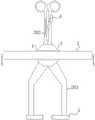
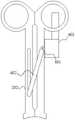
图1为本发明提出的一种用于骨科手术的夹持引导装置的结构示意图;FIG. 1 is a schematic structural diagram of a clamping and guiding device for orthopaedic surgery proposed by the present invention;
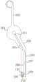
图2为本发明提出的一种用于骨科手术的夹持引导装置夹持组件的结构示意图;FIG. 2 is a schematic structural diagram of a clamping assembly of a clamping guide device for orthopaedic surgery proposed by the present invention;
图3为本发明提出的一种用于骨科手术的夹持引导装置支撑组件的结构示意图;3 is a schematic structural diagram of a support assembly of a clamping and guiding device for orthopaedic surgery proposed by the present invention;
图4为本发明提出的一种用于骨科手术的夹持引导装置引导盘的结构示意图;4 is a schematic structural diagram of a guide plate of a clamping and guiding device for orthopaedic surgery proposed by the present invention;
图5为本发明提出的一种用于骨科手术的夹持引导装置捆绑组件的结构示意图;5 is a schematic structural diagram of a clamping and guiding device binding assembly for orthopaedic surgery proposed by the present invention;
图6为本发明提出的一种用于骨科手术的夹持引导装置固定组件的结构示意图;6 is a schematic structural diagram of a clamping and guiding device fixing assembly for orthopaedic surgery proposed by the present invention;
图7为本发明提出的一种用于骨科手术的夹持引导装置限制板的结构示意图;7 is a schematic structural diagram of a limiting plate of a clamping and guiding device for orthopaedic surgery proposed by the present invention;
图8为本发明提出的一种用于骨科手术的夹持引导装置转接机构的结构示意图。FIG. 8 is a schematic structural diagram of a clamping and guiding device transfer mechanism for orthopaedic surgery proposed by the present invention.
图中:1支撑组件、101支撑套环、102支撑轴、103引导盘、104挤压通道、2夹持组件、201转动板、202手持杆、203延伸板、204夹持杆、205引导槽、206空腔、207活动板、208安装腔、209转轴、210转接齿轮、211拉杆、212底部齿轮、3捆绑组件、301基板、302转接机构、303调节板、304挤压机构、310固定杆、311支撑板、312移动杆、4固定组件、401支柱、402第一拉杆、403限制板、5引导组件。In the figure: 1 support assembly, 101 support collar, 102 support shaft, 103 guide plate, 104 squeeze channel, 2 clamp assembly, 201 rotation plate, 202 hand lever, 203 extension plate, 204 clamp rod, 205 guide groove , 206 cavity, 207 movable plate, 208 installation cavity, 209 shaft, 210 transfer gear, 211 pull rod, 212 bottom gear, 3 binding components, 301 base plate, 302 transfer mechanism, 303 adjustment plate, 304 extrusion mechanism, 310 Fixed rod, 311 support plate, 312 moving rod, 4 fixed components, 401 pillars, 402 first pull rod, 403 limit plate, 5 guide components.
具体实施方式Detailed ways
下面将结合本发明实施例中的附图,对本发明实施例中的技术方案进行清楚、完整地描述,显然,所描述的实施例仅仅是本发明一部分实施例,而不是全部的实施例。The technical solutions in the embodiments of the present invention will be clearly and completely described below with reference to the accompanying drawings in the embodiments of the present invention. Obviously, the described embodiments are only a part of the embodiments of the present invention, but not all of the embodiments.
参照图1-8,一种用于骨科手术的夹持引导装置,包括:支撑组件1,支撑组件1包括环形结构的支撑套环101,固接在支撑套环101内圈的支撑轴102,支撑轴102的外圈固定套接有两组平行设置的引导盘103;1-8, a clamping and guiding device for orthopaedic surgery includes: a support assembly 1, the support assembly 1 includes a
夹持组件2,设置有两组且与支撑轴102活动套接,夹持组件2设置有用于固定的固定组件4以及用于引导的引导组件5,两组夹持组件2沿支撑轴102为轴线呈剪刀型分布,固定组件4固接有延伸至夹持组件2端部的推动部,推动部用于带动固定组件4的固定;The clamping assembly 2 is provided with two groups and is movably sleeved with the
捆绑组件3,设置在支撑套环101的外圈,且与支撑套环101活动套接。The binding assembly 3 is arranged on the outer ring of the
进一步的,夹持组件2包括位于两组引导盘103之间且与支撑轴102活动套接的转动板201,转动板201的一端固接有位于支撑套环101一端开口处的手持杆202,转动板201的另一端固接置有位于支撑套环101另一端开口处的延伸板203,延伸板203远离引导盘103的一端固接有夹持杆204。Further, the clamping assembly 2 includes a
尤其是,延伸板203靠近相邻引导盘103的一侧开设沿转动板201的直径方向设置的引导槽205,夹持杆204的内部预留有沿其长度方向设置的空腔206,且空腔206靠近延伸板203的一端与引导槽205连通,空腔206的一侧开设有与其连通的安装腔208,安装腔208的内部设置有与夹持杆204活动套接的转轴209,转轴209伸出夹持杆204的一端与引导组件5固定连接,转轴209的外圈固定套接有位于安装腔208内部的底部齿轮212,底部齿轮212靠近延伸板203的一侧啮合有转接齿轮210,转接齿轮210啮合有位于空腔206内部的活动板207,活动板207靠近转动板201的一端固接有拉杆211。In particular, the side of the
值得说明的,活动板207采用柔性材料制成,活动板207开设有与转接齿轮210啮合的齿。It should be noted that the
此外,捆绑组件3包括与支撑套环101外圈活动套接的长条形结构的基板301,基板301的两侧均设置与其平行设置的调节板303,调节板303与基板301之间通过转接机构302活动连接,调节板303靠近基板301的一侧安装有用于限制转接机构302运动的挤压机构304。In addition, the binding assembly 3 includes a
除此之外,转接机构302包括固定杆310以及与固定杆310平行设置的移动杆312,固定杆310的外圈固定套接有沿其长度方向等距设置的支撑板311,且支撑板311与相邻的移动杆312固定套接,相邻支撑板311之间安装有位于移动杆312外圈固定套接的限制套环,限制套环的外圈开设有沿其轴线阵列分布的卡齿,两组转接机构302之间呈交错设置。In addition, the
优选的,基板301的两侧均开设有沿其长度方向设置容纳槽,固定杆310与容纳槽的内侧壁活动套接,且基板301同一侧的两根固定杆310分布在基板301的两端,调节板303靠近基板301的一侧开设有沿其长度方向设置的安装槽,安装槽的顶部以及底部内侧壁均开设有沿其长度方向设置的引导滑槽,移动杆312位于两组引导滑槽之间,且移动杆312与引导滑槽滑道套接,相邻支撑板311之间的距离不小于支撑板311的宽度。Preferably, both sides of the
更进一步的,挤压机构304包括位于调节板303的安装槽内部的挤压板,挤压板位于转接机构302远离相邻基板301的一侧,挤压板靠近基板301的一侧两端固接有与卡齿卡接的卡块,挤压板远离基板301的一端固接有推杆,推杆另一端螺纹套接有与调节板303活动套接的转动套筒,且转动套筒贯穿调节板303,调节板303的两端固接有捆绑带。Further, the
实施例一:Example 1:
固定组件4包括与其中一个手持杆202固接的支柱401,支柱401的外圈活动套接有第一拉杆402,且第一拉杆402远离支柱401的一端与相邻的手持杆202活动套接,设置有支柱401的手持杆202外侧设置有L型结构的限制板403,且限制板403位于两组手持杆202相互远离的一侧,限制板403靠近相邻手持杆202的一侧开设有沿手持杆202长度方向等距设置的阻挡齿,第一拉杆402靠近限制板403的一端开设有沿支柱401轴线阵列设置的对接卡槽,且对接卡槽与阻挡齿卡接,支柱401的两侧均安装有与相邻手持杆202固接的导向杆,导向杆另一端滑动套接有与限制板403固接的套管,导向杆伸入导管的一端固接有与限制板403固接的弹簧,与支柱401相邻的手持杆202开设有沿其长度方向设置的滑动槽,滑动槽的内部滑动套接有与第一拉杆402固接的连接杆。The fixing assembly 4 includes a
实施例二:Embodiment 2:
推动部包括与限制板403固接的推动板,手持杆202远离转动板201的一端固接有手指套环,推动板延伸至相邻的手指套环位置。The push portion includes a push plate fixed with the
实施例三:Embodiment three:
引导组件5包括与转轴209固接的接触杆,接触杆的中间开设有沿其长度方向设置的引导通道,两组接触杆沿同一条轴线设置,两组接触杆相互靠近的一端均设置有锯齿状的夹持凹槽,夹持凹槽使得与患者夹持牢固,引导盘103相邻转动板201的一侧开设有圆弧形结构的挤压通道104,且挤压通道104与拉杆211活动套接,挤压通道104与引导盘103的轴线之间的距离沿其长度方向逐渐变大。The guide assembly 5 includes a contact rod that is fixedly connected with the
工作原理:夹持的时候,首先将拇指伸入位于安装有支柱401的手持杆202上的手指套环中,同时拇指端部与推动部的推动板接近,然后食指从另一个手指套环伸入,拇指伸直然后推动推动板沿支柱401的长度方向移动,推动板带动限制板403移动,从而使限制板403向一侧移动,限制板403上的阻挡齿向远离第一拉杆402上的对接卡槽的方向移动,这时候阻挡齿与对接卡槽脱离接触,当张开手部的拇指和食指的时候两组手持杆202向相互远离的方向沿支撑轴102偏转从而使夹持组件2张开;Working principle: When clamping, first put the thumb into the finger loop located on the hand-held
这时候由于引导盘103与支撑轴102固定,引导盘103和转动板201发生相对运动,从而使位于拉杆211沿引导盘103沿挤压通道104移动,从而使拉杆211带动活动板207沿其长度方向移动,然后活动板207在移动的时候与转接齿轮210发生相对运动,从而使转接齿轮210转动,转接齿轮210带动底部齿轮212转动,然后使转轴209转动,转轴209带动引导组件5发生转向移动,由于夹持组件2沿支撑轴102呈剪刀式分布,使的两组引导组件5在张开以及收拢的整个过程中始终位于同一条直线上,开孔的时候钻头沿引导组件5向内伸入,使贯穿孔位置准确,在穿引的时候钢针从其中一个引导组件5伸入从另一个引导组件5伸出,有效避免穿引偏斜,在不同角度夹持的时候确保在同一条直线上,方便对患者进行开孔以及穿引操作;At this time, since the
在固定的时候根据患者病患位置的不同,转动捆绑组件3上的基板310,基板301始终与患者的病患位置的长度方向垂直,转动位于调节板303上的转动套筒,使转动套筒带动推杆运动,然后挤压板向相邻移动杆312远离的方向移动,限制套环上的卡齿与挤压板上的卡块脱离接触,然后拉动调节板303使调节板303向远离基板301的方向移动,固定的时候安装上述相反的步骤,使转动套筒向相反的方向转动,将调节板303上的捆绑带与患者进行捆绑,从而调节捆绑位置以及与夹持位置之间的方向,实现正面上方进行捆绑,侧边进行夹持,适合不同位置的夹持操作;When fixing, according to the position of the patient, rotate the
该设计方便对患者进行夹持固定,从正面上方进行捆绑固定,适合不同位置的夹持尤其是侧边位置的夹持,使两组引导组件始终处于同一条直线上,方便对患者进行开孔以及穿引操作,提高手术质量减轻医护人员的操作难度,提高手术效率和质量。The design is convenient for clamping and fixing the patient, and it can be bundled and fixed from the top of the front. It is suitable for clamping at different positions, especially the clamping at the side position, so that the two sets of guide components are always on the same straight line, which is convenient for opening the patient. As well as threading operation, improve the quality of the operation, reduce the difficulty of operation for medical staff, and improve the efficiency and quality of the operation.
在本发明的描述中,需要理解的是,术语“中心”、“纵向”、“横向”、“长度”、“宽度”、“厚度”、“上”、“下”、“前”、“后”、“左”、“右”、“竖直”、“水平”、“顶”、“底”、“内”、“外”、“顺时针”、“逆时针”等指示的方位或位置关系为基于附图所示的方位或位置关系,仅是为了便于描述本发明和简化描述,而不是指示或暗示所指的设备或元件必须具有特定的方位、以特定的方位构造和操作,因此不能理解为对本发明的限制。In the description of the present invention, it should be understood that the terms "center", "longitudinal", "lateral", "length", "width", "thickness", "upper", "lower", "front", " rear, left, right, vertical, horizontal, top, bottom, inside, outside, clockwise, counterclockwise, etc., or The positional relationship is based on the orientation or positional relationship shown in the drawings, which is only for the convenience of describing the present invention and simplifying the description, rather than indicating or implying that the referred device or element must have a specific orientation, be constructed and operated in a specific orientation, Therefore, it should not be construed as a limitation of the present invention.
此外,术语“第一”、“第二”仅用于描述目的,而不能理解为指示或暗示相对重要性或者隐含指明所指示的技术特征的数量。由此,限定有“第一”、“第二”的特征可以明示或者隐含地包括一个或者更多个该特征。在本发明的描述中,“多个”的含义是两个或两个以上,除非另有明确具体的限定。In addition, the terms "first" and "second" are only used for descriptive purposes, and should not be construed as indicating or implying relative importance or implying the number of indicated technical features. Thus, a feature defined as "first" or "second" may expressly or implicitly include one or more of that feature. In the description of the present invention, "plurality" means two or more, unless otherwise expressly and specifically defined.
以上所述,仅为本发明较佳的具体实施方式,但本发明的保护范围并不局限于此,任何熟悉本技术领域的技术人员在本发明揭露的技术范围内,根据本发明的技术方案及其发明构思加以等同替换或改变,都应涵盖在本发明的保护范围之内。The above description is only a preferred embodiment of the present invention, but the protection scope of the present invention is not limited to this. The equivalent replacement or change of the inventive concept thereof shall be included within the protection scope of the present invention.
Claims (8)
Translated fromChinesePriority Applications (1)
| Application Number | Priority Date | Filing Date | Title |
|---|---|---|---|
| CN201910793144.XACN110464419B (en) | 2019-08-27 | 2019-08-27 | Clamping and guiding device for orthopedic surgery |
Applications Claiming Priority (1)
| Application Number | Priority Date | Filing Date | Title |
|---|---|---|---|
| CN201910793144.XACN110464419B (en) | 2019-08-27 | 2019-08-27 | Clamping and guiding device for orthopedic surgery |
Publications (2)
| Publication Number | Publication Date |
|---|---|
| CN110464419A CN110464419A (en) | 2019-11-19 |
| CN110464419Btrue CN110464419B (en) | 2020-08-11 |
Family
ID=68512195
Family Applications (1)
| Application Number | Title | Priority Date | Filing Date |
|---|---|---|---|
| CN201910793144.XAExpired - Fee RelatedCN110464419B (en) | 2019-08-27 | 2019-08-27 | Clamping and guiding device for orthopedic surgery |
Country Status (1)
| Country | Link |
|---|---|
| CN (1) | CN110464419B (en) |
Family Cites Families (8)
| Publication number | Priority date | Publication date | Assignee | Title |
|---|---|---|---|---|
| US20090012539A1 (en)* | 2007-07-03 | 2009-01-08 | Gary Louis Zohman | Surgical clamping instruments and methods |
| GB201009319D0 (en)* | 2010-06-03 | 2010-07-21 | Univ Robert Gordon | Surgical guide device |
| CN201977876U (en)* | 2011-01-05 | 2011-09-21 | 张德辉 | Orthopedic positioning perforating clamp |
| US9161772B2 (en)* | 2011-08-04 | 2015-10-20 | Olympus Corporation | Surgical instrument and medical manipulator |
| CN203195757U (en)* | 2013-04-15 | 2013-09-18 | 中国医学科学院北京协和医院 | Fracture-positioning forceps |
| EP3072462B1 (en)* | 2015-03-27 | 2017-10-04 | DePuy Ireland Unlimited Company | Orthopaedic surgical instrument system |
| CN107260296B (en)* | 2017-07-04 | 2023-11-24 | 吴旭华 | Medical needle guide forceps |
| CN107468302A (en)* | 2017-09-05 | 2017-12-15 | 张红云 | A kind of clinical telescopic haemostatic clamp of internal medicine |
- 2019
- 2019-08-27CNCN201910793144.XApatent/CN110464419B/ennot_activeExpired - Fee Related
Also Published As
| Publication number | Publication date |
|---|---|
| CN110464419A (en) | 2019-11-19 |
Similar Documents
| Publication | Publication Date | Title |
|---|---|---|
| US11000269B2 (en) | Medical instrument | |
| US10543049B2 (en) | Medical manipulator | |
| BRPI0419039B1 (en) | surgical stapling instrument | |
| EP2804545B1 (en) | Surgical bone holding forceps with a drilling guide | |
| CN109984825B (en) | Be used for CT puncture to intervene and use guiding mechanism | |
| CN106028958A (en) | Oral retraction apparatus and methods | |
| PT2720600T (en) | Articulating ophthalmic surgical probe | |
| JP6307066B2 (en) | Surgical instrument with discrete articulation section with cam | |
| GB2522986A (en) | Laparoscopic radiofrequency surgical device | |
| CN103957849A (en) | Small format surgical instruments with adjustable mounts | |
| US10470758B2 (en) | Suturing device | |
| CN106551715A (en) | A kind of universal laminectomy rongeur | |
| CN110464419B (en) | Clamping and guiding device for orthopedic surgery | |
| CN102846349B (en) | A kind of vertebral canal expansion Wicresoft cutting tool | |
| CN204520876U (en) | The direction-changeable rongeur of a kind of Wicresoft | |
| CN109452966A (en) | A kind of reduction forceps of bone of positioning and guiding | |
| CN111388080A (en) | Orthopedic parallel pressurizing positioner | |
| KR101111213B1 (en) | Gear and cam type anastomosis device | |
| CN216257298U (en) | Kirschner wire auxiliary guiding diaphysis fracture operation reduction device | |
| ES2932159T3 (en) | Stapling device with continuously parallel jaws | |
| CN113729845A (en) | Kirschner wire auxiliary guiding diaphysis fracture operation reduction device | |
| CN205181483U (en) | Controllable medical probe's experiment bench | |
| CN110507399B (en) | A directional navigation device for bone distraction | |
| KR101957221B1 (en) | Guiding apparatus for surgical tool | |
| CN114917010B (en) | Adjustable patella repositioning fixator |
Legal Events
| Date | Code | Title | Description |
|---|---|---|---|
| PB01 | Publication | ||
| PB01 | Publication | ||
| SE01 | Entry into force of request for substantive examination | ||
| SE01 | Entry into force of request for substantive examination | ||
| GR01 | Patent grant | ||
| GR01 | Patent grant | ||
| CF01 | Termination of patent right due to non-payment of annual fee | ||
| CF01 | Termination of patent right due to non-payment of annual fee | Granted publication date:20200811 |