CN110455802B - Alloy analysis device and method based on visual recognition - Google Patents
Alloy analysis device and method based on visual recognitionDownload PDFInfo
- Publication number
- CN110455802B CN110455802BCN201910797224.2ACN201910797224ACN110455802BCN 110455802 BCN110455802 BCN 110455802BCN 201910797224 ACN201910797224 ACN 201910797224ACN 110455802 BCN110455802 BCN 110455802B
- Authority
- CN
- China
- Prior art keywords
- alloy
- sample
- analysis
- range finder
- laser range
- Prior art date
- Legal status (The legal status is an assumption and is not a legal conclusion. Google has not performed a legal analysis and makes no representation as to the accuracy of the status listed.)
- Expired - Fee Related
Links
Images


Classifications
- B—PERFORMING OPERATIONS; TRANSPORTING
- B25—HAND TOOLS; PORTABLE POWER-DRIVEN TOOLS; MANIPULATORS
- B25J—MANIPULATORS; CHAMBERS PROVIDED WITH MANIPULATION DEVICES
- B25J11/00—Manipulators not otherwise provided for
- B—PERFORMING OPERATIONS; TRANSPORTING
- B25—HAND TOOLS; PORTABLE POWER-DRIVEN TOOLS; MANIPULATORS
- B25J—MANIPULATORS; CHAMBERS PROVIDED WITH MANIPULATION DEVICES
- B25J9/00—Programme-controlled manipulators
- B25J9/16—Programme controls
- B25J9/1656—Programme controls characterised by programming, planning systems for manipulators
- B25J9/1664—Programme controls characterised by programming, planning systems for manipulators characterised by motion, path, trajectory planning
- B—PERFORMING OPERATIONS; TRANSPORTING
- B25—HAND TOOLS; PORTABLE POWER-DRIVEN TOOLS; MANIPULATORS
- B25J—MANIPULATORS; CHAMBERS PROVIDED WITH MANIPULATION DEVICES
- B25J9/00—Programme-controlled manipulators
- B25J9/16—Programme controls
- B25J9/1694—Programme controls characterised by use of sensors other than normal servo-feedback from position, speed or acceleration sensors, perception control, multi-sensor controlled systems, sensor fusion
- B25J9/1697—Vision controlled systems
- G—PHYSICS
- G01—MEASURING; TESTING
- G01N—INVESTIGATING OR ANALYSING MATERIALS BY DETERMINING THEIR CHEMICAL OR PHYSICAL PROPERTIES
- G01N21/00—Investigating or analysing materials by the use of optical means, i.e. using sub-millimetre waves, infrared, visible or ultraviolet light
- G01N21/84—Systems specially adapted for particular applications
Landscapes
- Engineering & Computer Science (AREA)
- Robotics (AREA)
- Mechanical Engineering (AREA)
- Physics & Mathematics (AREA)
- Health & Medical Sciences (AREA)
- Life Sciences & Earth Sciences (AREA)
- Chemical & Material Sciences (AREA)
- Analytical Chemistry (AREA)
- Biochemistry (AREA)
- General Health & Medical Sciences (AREA)
- General Physics & Mathematics (AREA)
- Immunology (AREA)
- Pathology (AREA)
- Sampling And Sample Adjustment (AREA)
- Length Measuring Devices By Optical Means (AREA)
Abstract
Description
Translated fromChinese技术领域technical field
本发明涉及一种合金分析装置,具体涉及一种基于视觉识别的合金分析装置及方法,属于高线合金分析的技术领域。The invention relates to an alloy analysis device, in particular to an alloy analysis device and method based on visual recognition, and belongs to the technical field of high-wire alloy analysis.
背景技术Background technique
合金分析仪是基于X射线理论而诞生的,它主要用于军工、航天、钢铁、石化、电力、制药等领域金属材料中元素成份的现场测定,是伴随世界经济崛起的工业和军事制造领域必不可少的快速成份鉴定工具。Alloy Analyzer was born based on X-ray theory. It is mainly used for on-site determination of elemental components in metal materials in the fields of military industry, aerospace, steel, petrochemical, electric power, pharmaceuticals, etc. Indispensable rapid ingredient identification tool.
目前,现有的合金分析仪需要人工握持靠近待测样品进行检测,费时费力,效率低下,且不适用于极限环境下的使用。例如,进行高线样品的合金分析时,现场为高温环境,如采用人工握持合金分析仪进行检测,会严重影响工作人员的身心健康。At present, the existing alloy analyzer needs to be manually held close to the sample to be tested, which is time-consuming, laborious, inefficient, and not suitable for use in extreme environments. For example, when performing alloy analysis of high-line samples, the site is in a high-temperature environment. If the alloy analyzer is manually held for detection, it will seriously affect the physical and mental health of the staff.
发明内容Contents of the invention
发明目的:针对上述问题,本发明的目的是提供一种基于视觉识别的合金分析装置,以机器人替代人工握持合金分析仪,提高效率和稳定性,且适用于极限环境下的样品分析。Purpose of the invention: In view of the above problems, the purpose of the present invention is to provide an alloy analysis device based on visual recognition, which uses a robot to replace the manual holding alloy analyzer, improves efficiency and stability, and is suitable for sample analysis in extreme environments.
技术方案:基于视觉识别的合金分析装置,包括控制器、机器人、支架、合金分析仪,所述机器人、支架、合金分析仪依次连接,还包括用于识别出待检测样品上分析点的视觉识别装置,所述视觉识别装置固定在所述支架上,所述合金分析仪、视觉识别装置相邻设置且均朝向待检测样品,所述机器人、合金分析仪、视觉识别装置分别与所述控制器信号关联;所述视觉识别装置识别出所述待检测样品上的分析点后,所述机器人驱动所述合金分析仪接近该分析点进行合金分析。Technical solution: an alloy analysis device based on visual recognition, including a controller, a robot, a bracket, and an alloy analyzer, the robot, bracket, and alloy analyzer are connected in sequence, and also includes a visual recognition for identifying analysis points on the sample to be tested device, the visual recognition device is fixed on the bracket, the alloy analyzer and the visual recognition device are adjacently arranged and both face the sample to be tested, the robot, the alloy analyzer, and the visual recognition device are respectively connected to the controller Signal correlation: after the visual recognition device recognizes the analysis point on the sample to be detected, the robot drives the alloy analyzer to approach the analysis point for alloy analysis.
本发明的原理是:使用时,首先以视觉识别装置识别出待检测样品的最佳分析点后,反馈位置信号给控制器,控制器发送驱动信号给机器人,机器人信号驱动合金分析仪接近该待检测样品的最佳分析点,进行合金分析。The principle of the present invention is: when in use, first use the visual recognition device to identify the best analysis point of the sample to be tested, then feed back the position signal to the controller, the controller sends a driving signal to the robot, and the robot signal drives the alloy analyzer to approach the sample to be tested. Detect the best analysis point of the sample for alloy analysis.
进一步,还包括挤压保护装置,所述挤压保护装置包括伸缩件、安装座,所述伸缩件通过所述安装座与所述支架固定,所述伸缩件前端连接所述合金分析仪,所述伸缩件与所述控制器信号关联;所述合金分析仪与所述待检测样品发生接触挤压后,所述伸缩件收缩以防止所述合金分析仪受挤压破坏。本结构中,当机器人驱动合金分析仪接近最佳分析点时,如发生接触挤压现象,伸缩件收缩以防止合金分析仪被破坏。Further, it also includes an extrusion protection device, the extrusion protection device includes a telescopic piece and a mounting seat, the telescopic piece is fixed to the bracket through the mounting seat, the front end of the telescopic piece is connected to the alloy analyzer, and the The telescopic member is associated with the controller signal; after the alloy analyzer is contacted and squeezed with the sample to be detected, the telescopic member shrinks to prevent the alloy analyzer from being damaged by extrusion. In this structure, when the robot drives the alloy analyzer close to the optimal analysis point, if contact extrusion occurs, the telescopic part shrinks to prevent the alloy analyzer from being damaged.
进一步,所述挤压保护装置还包括第一激光测距仪、挡光板,所述第一激光测距仪固定在所述支架上,所述挡光板固定在所述合金分析仪上,所述挡光板位于所述第一激光测距仪的测距直线上,所述第一激光测距仪与所述控制器信号关联;所述第一激光测距仪与所述挡光板相配合以测量所述伸缩件的收缩距离。本结构中,通过第一激光测距仪和挡光板的配合检测伸缩件的收缩距离,当该收缩距离超过预先设定的安全距离时,第一激光测距仪发送停机信号给控制器,控制器及时信号控制机器人停机,进一步防止合金分析仪被挤压破坏。Further, the extrusion protection device also includes a first laser range finder and a light baffle, the first laser range finder is fixed on the bracket, the light baffle is fixed on the alloy analyzer, the The light baffle is located on the ranging straight line of the first laser range finder, and the first laser range finder is associated with the controller signal; the first laser range finder cooperates with the light baffle to measure The contraction distance of the telescopic element. In this structure, the shrinkage distance of the telescopic element is detected through the cooperation of the first laser rangefinder and the light barrier. When the shrinkage distance exceeds the preset safety distance, the first laser rangefinder sends a shutdown signal to the controller to control The timely signal of the controller controls the shutdown of the robot, further preventing the alloy analyzer from being crushed and damaged.
优选的,所述伸缩件包括但不限定为气缸。Preferably, the telescopic member includes but is not limited to a cylinder.
进一步,所述挤压保护装置还包括浮动接头、延伸板,所述延伸板的前端固定所述合金分析仪、后端通过所述浮动接头连接所述伸缩件,以优化连接结构。Further, the extrusion protection device also includes a floating joint and an extension plate, the front end of the extension plate is fixed to the alloy analyzer, and the rear end is connected to the telescopic member through the floating joint, so as to optimize the connection structure.
进一步,所述支架上设置有导轨,所述导轨内设置有滑块,所述滑块上连接所述延伸板,以对延伸板形成支撑,强化结构的稳定性。Further, guide rails are provided on the bracket, and sliders are provided in the guide rails, and the extension boards are connected to the sliders to support the extension boards and strengthen the stability of the structure.
进一步,所述第一激光测距仪、伸缩件分别设置于所述支架的两个相邻平面上,所述挡光板为“L”型,一侧与所述延伸板固定、另一侧延伸至与所述第一激光测距仪所对应的位置。本结构中,对第一激光测距仪、伸缩件的设置位置进行了优化,防止两者相互之间发生干涉。Further, the first laser rangefinder and the telescopic member are respectively arranged on two adjacent planes of the bracket, and the light baffle is in an "L" shape, one side is fixed to the extension plate, and the other side extends to the position corresponding to the first laser range finder. In this structure, the arrangement positions of the first laser range finder and the telescopic member are optimized to prevent the interference between them.
优选的,所述视觉识别装置包括分别固定在所述支架上的结构光发生装置、工业照相机,所述结构光发生装置、工业照相机均朝向所述待检测样品且分别与所述控制器信号关联;所述结构光发生装置发射的结构光经所述待检测样品反射后被所述工业照相机接收,所述工业照相机用于拍照识别所述待检测样品上的分析点。Preferably, the visual recognition device includes a structured light generating device and an industrial camera respectively fixed on the support, and the structured light generating device and the industrial camera are all directed towards the sample to be detected and are respectively associated with the controller signal ; The structured light emitted by the structured light generating device is received by the industrial camera after being reflected by the sample to be detected, and the industrial camera is used to take pictures and identify analysis points on the sample to be detected.
进一步,所述结构光发生装置、工业照相机的轴心处于同一竖直平面上。本结构中,结构光发生装置和工业相机采用上下安装的设置方式,尤其适用于高线钢卷等圆柱型待检测样品的最佳分析点识别,结构光发生装置发出的结构光照射到圆柱型待检测样品上后,被工业照相机接收的反射光会因为角度和距离不同而存在差异,便于让工业照相机捕捉到圆柱型待检测样品最凸出的一个点,即最佳合金分析点。Further, the axes of the structured light generating device and the industrial camera are on the same vertical plane. In this structure, the structured light generating device and the industrial camera are installed up and down, which is especially suitable for the identification of the best analysis points of cylindrical samples to be tested such as high wire steel coils. The structured light emitted by the structured light generating device irradiates the cylindrical After the sample to be tested, the reflected light received by the industrial camera will vary due to different angles and distances, so that the industrial camera can capture the most protruding point of the cylindrical sample to be tested, which is the best alloy analysis point.
进一步,所述视觉识别装置还包括固定在所述支架上的第二激光测距仪,所述第二激光测距仪与所述控制器信号关联,所述第二激光测距仪朝向所述待检测样品,用于测量所述工业照相机与所述待检测样品之间的距离。本结构中,以第二激光测距仪检测工业照相机与待检测样品之间的大致距离,然后通过机器人信号驱动结构光发生装置和工业照相机靠近待检测样品,便于结构光发生装置和工业照相机配合,寻找最佳合金分析点。Further, the visual identification device also includes a second laser range finder fixed on the bracket, the second laser range finder is associated with the controller signal, and the second laser range finder faces the The sample to be detected is used to measure the distance between the industrial camera and the sample to be detected. In this structure, the second laser rangefinder is used to detect the approximate distance between the industrial camera and the sample to be inspected, and then the structured light generator and the industrial camera are driven close to the sample to be inspected by the robot signal, which facilitates the cooperation between the structured light generator and the industrial camera , to find the best alloy analysis point.
进一步,所述视觉识别装置还包括固定在所述合金分析仪上的第三激光测距仪,所述第三激光测距仪朝向所述待检测样品且与所述控制器信号关联,用于测量所述合金分析仪与所述分析点之间的距离,以便于机器人信号驱动合金分析仪接近该分析点进行合金分析。Further, the visual identification device also includes a third laser range finder fixed on the alloy analyzer, the third laser range finder faces the sample to be detected and is associated with the controller signal for The distance between the alloy analyzer and the analysis point is measured, so that the robot signal drives the alloy analyzer to approach the analysis point for alloy analysis.
进一步,所述视觉识别装置还包括底板、连接板和护罩,所述底板正面固定所述结构光发生装置和工业照相机、背面通过所述连接板与所述支架固定,所述护罩前端为一透明面板、后端固定在所述底板上、内侧包裹保护所述结构光发生装置和工业照相机、外侧固设所述第二激光测距仪。本结构中,通过护罩对工业照相机和结构光发生装置形成保护,使其免受外部灰尘干扰。Further, the visual identification device also includes a base plate, a connecting plate and a shield, the front of the base plate fixes the structured light generating device and the industrial camera, the back is fixed with the bracket through the connecting plate, and the front end of the shield is A transparent panel, the rear end of which is fixed on the bottom plate, the inner side wraps and protects the structured light generating device and the industrial camera, and the outer side is fixed with the second laser range finder. In this structure, the protective cover protects the industrial camera and the structured light generating device from external dust interference.
优选的,所述机器人为六轴机器人。Preferably, the robot is a six-axis robot.
优选的,所述支架为“L”型,直角处固定有支撑杆。Preferably, the bracket is in an "L" shape, and support rods are fixed at right angles.
本发明还提供了利用上述装置进行合金分析的方法,包括以下步骤:The present invention also provides a method for alloy analysis using the above-mentioned device, comprising the following steps:
S1:控制器发送启动信号给机器人,机器人通过支架驱动合金分析仪、视觉识别装置靠近待检测样品;S1: The controller sends a start signal to the robot, and the robot drives the alloy analyzer and visual recognition device close to the sample to be tested through the bracket;
S2:第二激光测距仪实时测定工业照相机与待检测样品之间的距离,并实时反馈给控制器,控制器中预设有拍摄距离值,当第二激光测距仪反馈的距离等于控制器预设的拍摄距离值时,控制器信号控制机器人停机;S2: The second laser range finder measures the distance between the industrial camera and the sample to be detected in real time, and feeds back to the controller in real time. The controller presets the shooting distance value. When the distance fed back by the second laser range finder is equal to When the shooting distance value preset by the controller is reached, the controller signal controls the robot to stop;
S3:控制器信号控制结构光发生装置发射结构光,同时信号控制工业照相机启动,结构光经待检测样品反射后被工业照相机接收,工业照相机连续拍摄数张待检测样品的图像后反馈给控制器;S3: The controller signal controls the structured light generator to emit structured light. At the same time, the signal controls the industrial camera to start. The structured light is reflected by the sample to be tested and then received by the industrial camera. The industrial camera continuously captures several images of the sample to be tested and then feeds back to the controller. ;
S4:控制器根据该反馈的图像进行信息处理,得到待检测样品合金分析的最佳采样点,并利用三角测距原理获得最佳采样点的三维坐标信息;S4: The controller performs information processing according to the feedback image to obtain the best sampling point for alloy analysis of the sample to be tested, and obtains the three-dimensional coordinate information of the best sampling point by using the principle of triangular ranging;
S5:控制器信号控制第三激光测距仪启动,测量合金分析仪与该最佳采样点之间的距离,并反馈给控制器;S5: The controller signal controls the start of the third laser range finder, measures the distance between the alloy analyzer and the optimal sampling point, and feeds back to the controller;
S6:控制器信号控制机器人驱动合金分析仪接近该最佳采样点,进行合金分析。S6: The controller signal controls the robot to drive the alloy analyzer to approach the optimal sampling point for alloy analysis.
进一步,第二激光测距仪为并排设置的一组,控制器根据每个激光测距仪反馈的距离计算出平均值,然后以该平均值与拍摄距离值进行比较。Further, the second laser range finder is a group arranged side by side, and the controller calculates an average value according to the distance fed back by each laser range finder, and then compares the average value with the shooting distance value.
有益效果:与现有技术相比,本发明的优点是:1、以机器人替代人工握持合金分析仪,提高检测效率和稳定性,且适用于极限环境下的样品分析;2、设置有挤压保护结构,避免机器人驱动合金分析仪时,合金分析仪与待检测样品发生接触挤压而破坏;3、视觉识别结构中,具备双重测距定位功能,首先通过第二激光测距仪测量工业照相机与待检测样品的大致距离,以便于其寻找最佳分析点,再通过第三激光测距仪精确测量合金分析仪与该最佳分析点的距离,便于机器人驱动合金分析仪接近最佳分析点进行合金分析。Beneficial effects: compared with the prior art, the present invention has the following advantages: 1. A robot is used instead of manually holding the alloy analyzer to improve detection efficiency and stability, and it is suitable for sample analysis in extreme environments; 2. It is equipped with a squeeze The pressure protection structure prevents the alloy analyzer from being damaged due to contact and extrusion between the alloy analyzer and the sample to be tested when the robot drives the alloy analyzer; 3. In the visual recognition structure, it has dual ranging and positioning functions. The approximate distance between the camera and the sample to be tested, so that it can find the best analysis point, and then use the third laser rangefinder to accurately measure the distance between the alloy analyzer and the best analysis point, so that the robot can drive the alloy analyzer to approach the best analysis point for alloy analysis.
附图说明Description of drawings
图1为本发明装置使用状态示意图。Fig. 1 is a schematic diagram of the use state of the device of the present invention.
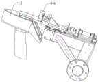
图2为支架与挤压保护装置、视觉识别装置的连接结构示意图。Fig. 2 is a schematic diagram of the connection structure of the bracket, the extrusion protection device and the visual identification device.
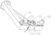
图3为挤压保护装置结构示意图。Fig. 3 is a structural schematic diagram of the extrusion protection device.
图4为导轨处剖视结构示意图。Figure 4 is a schematic cross-sectional structural view of the guide rail.
图5为第三激光测距仪结构示意图。Fig. 5 is a schematic structural diagram of the third laser range finder.
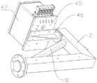
图6为视觉识别装置的正面视图。Fig. 6 is a front view of the visual identification device.
图7为视觉识别装置背面视图。Fig. 7 is a rear view of the visual identification device.
其中,各附图标记分别代表:1机器人;2支架;3合金分析仪;4视觉识别装置;41结构光发生装置;42工业照相机;43第二激光测距仪;44第三激光测距仪;45底板;46连接板;47护罩;5挤压保护装置;51安装座;52伸缩件;53第一激光测距仪;54挡光板;55浮动接头;56延伸板;6导轨;7滑块;8支撑杆;100待检测样品。Wherein, each reference sign respectively represents: 1 robot; 2 bracket; 3 alloy analyzer; 4 visual recognition device; 41 structured light generating device; 42 industrial camera; ; 45 bottom plate; 46 connecting plate; 47 shield; 5 extrusion protection device; 51 mounting seat; Slider; 8 support rods; 100 samples to be tested.
具体实施方式Detailed ways
下面结合附图和具体实施例,进一步阐明本发明,这些实施例仅用于说明本发明而不用于限制本发明的范围。The present invention is further illustrated below in conjunction with the accompanying drawings and specific examples, and these examples are only used to illustrate the present invention and are not intended to limit the scope of the present invention.
一种基于视觉识别的合金分析装置,如附图1~7所示,包括控制器、机器人1、支架2、合金分析仪3、视觉识别装置4、挤压保护装置5、导轨6、滑块7、支撑杆8。An alloy analysis device based on visual recognition, as shown in Figures 1 to 7, including a controller, a robot 1, a
本实施例中,机器人1采用六轴机器人,驱动更加灵活。支架2采用方管制成,整体呈“L”型,包括横向臂和径向臂,直角处固定有支撑杆8,以强化支撑结构,横向臂通过法兰连接机器人1,径向臂上分别固定连接视觉识别装置4、挤压保护装置5、导轨6,导轨6内设置有滑块7,挤压保护装置5前端连接合金分析仪3,合金分析仪3、视觉识别装置4相邻设置且均朝向待检测样品100。In this embodiment, the robot 1 adopts a six-axis robot, and the driving is more flexible. The
如附图3所示,本实施例中,挤压保护装置5包括安装座51、伸缩件52、第一激光测距仪53、挡光板54、浮动接头55、延伸板56。As shown in FIG. 3 , in this embodiment, the
伸缩件52通过安装座51与支架2的径向臂固定,延伸板56的前端固定合金分析仪3、后端通过浮动接头55连接伸缩件52、底部与滑块7固定。第一激光测距仪53固定在支架2的径向臂上,挡光板54固定在延伸板56上,挡光板54位于第一激光测距仪53的测距直线上。本实施例中,为防止伸缩件52、浮动接头55影响第一激光测距仪53的测距,第一激光测距仪53、伸缩件52分别设置于支架2径向臂的两个相邻径向平面上,同时,挡光板54采用“L”型结构,一侧与延伸板56固定、另一侧延伸至与第一激光测距仪53所对应的位置。此外,伸缩件52优选为气缸。The
如附图5~7所示,本实施例的视觉识别装置4包括结构光发生装置41、工业照相机42、第二激光测距仪43、第三激光测距仪44、底板45、连接板46和护罩47。As shown in accompanying
底板45正面固定结构光发生装置41和工业照相机42、背面通过连接板46与支架2的径向臂固定,护罩47前端为一透明面板、后端固定在底板45上、内侧包裹保护结构光发生装置41和工业照相机42、外侧固设第二激光测距仪43。结构光发生装置41、工业照相机42、第二激光测距仪43、第三激光测距仪44均朝向待检测样品100。结构光发生装置41发射的结构光经待检测样品反射后被工业照相机42接收,工业照相机42拍照识别待检测样品上的分析点。第二激光测距仪43用于测量工业照相机42与待检测样品之间的距离。第三激光测距仪44固定在合金分析仪3上,用于测量合金分析仪3与分析点之间的距离。本实施例中,结构光发生装置41、工业照相机42、第二激光测距仪43优选为由下至上排列设置,且结构光发生装置41、工业照相机42优选轴心处于同一竖直平面上。The
机器人1、合金分析仪3、结构光发生装置41、工业照相机42、第二激光测距仪43、第三激光测距仪44、气缸、第一激光测距仪53分别与控制器信号关联。The robot 1, the
本实施例的合金分析装置使用时,控制器信号控制视觉识别装置4接近待检测样品100,识别出待检测样品100上的最佳分析点,再驱动合金分析仪3接近该最佳分析点进行合金分析。进行合金分析时,如合金分析仪3与待检测样品100发生接触挤压时,通过挤压保护装置5形成保护。When the alloy analysis device of this embodiment is in use, the controller signal controls the
具体的,视觉识别装置4使用时,首先通过第二激光测距仪43测量工业照相机42与待检测样品100的距离,然后机器人1驱动工业照相机42与结构光发生装置41靠近待检测样品100,通过两者的配合寻找待检测样品100的最佳分析点,之后通过第三激光测距仪44测量合金分析仪3与该最佳分析点的距离,再通过机器人1驱动合金分析仪3接近该最佳分析点进行合金分析。Specifically, when the
挤压保护装置5使用时,当机器人1驱动合金分析仪3接近待检测样品100进行合金分析时,如合金分析仪3与待检测样品100发生接触挤压,气缸收缩,该收缩距离通过第一激光测距仪53与挡光板54的配合所检测,一旦该距离检测结果小于预先设定的安全距离,机器人1迅速停止工作以防止合金分析仪3受挤压破坏,之后在控制气缸恢复初始状态,起到保护和重复使用的效果。When the
具体的合金分析方法包括以下步骤:The specific alloy analysis method includes the following steps:
S1:控制器发送启动信号给机器人,机器人通过支架驱动合金分析仪、视觉识别装置靠近待检测样品;S1: The controller sends a start signal to the robot, and the robot drives the alloy analyzer and visual recognition device close to the sample to be tested through the bracket;
S2:第二激光测距仪实时测定工业照相机与待检测样品之间的距离,并实时反馈给控制器,控制器中预设有拍摄距离值,当第二激光测距仪反馈的距离等于控制器预设的拍摄距离值时,控制器信号控制机器人停机;其中,第二激光测距仪为并排设置的五个,控制器根据每个激光测距仪反馈的距离计算出平均值,然后以该平均值与拍摄距离值进行比较。S2: The second laser range finder measures the distance between the industrial camera and the sample to be detected in real time, and feeds back to the controller in real time. The controller presets the shooting distance value. When the distance fed back by the second laser range finder is equal to When the shooting distance value preset by the controller, the controller signal controls the robot to stop; among them, the second laser rangefinder is five arranged side by side, and the controller calculates the average value according to the distance fed back by each laser rangefinder, and then uses This average value is compared with the shooting distance value.
S3:控制器信号控制结构光发生装置发射结构光,同时信号控制工业照相机启动,结构光经待检测样品反射后被工业照相机接收,工业照相机连续拍摄数张待检测样品的图像后反馈给控制器;S3: The controller signal controls the structured light generator to emit structured light. At the same time, the signal controls the industrial camera to start. The structured light is reflected by the sample to be tested and then received by the industrial camera. The industrial camera continuously captures several images of the sample to be tested and then feeds back to the controller. ;
S4:控制器根据该反馈的图像进行信息处理,得到待检测样品合金分析的最佳采样点,并利用三角测距原理获得最佳采样点的三维坐标信息;S4: The controller performs information processing according to the feedback image to obtain the best sampling point for alloy analysis of the sample to be tested, and obtains the three-dimensional coordinate information of the best sampling point by using the principle of triangular ranging;
S5:控制器信号控制第三激光测距仪启动,测量合金分析仪与该最佳采样点之间的距离,并反馈给控制器;S5: The controller signal controls the start of the third laser range finder, measures the distance between the alloy analyzer and the optimal sampling point, and feeds back to the controller;
S6:控制器信号控制机器人驱动合金分析仪接近该最佳采样点,进行合金分析。S6: The controller signal controls the robot to drive the alloy analyzer to approach the optimal sampling point for alloy analysis.
Claims (9)
Translated fromChinesePriority Applications (1)
| Application Number | Priority Date | Filing Date | Title |
|---|---|---|---|
| CN201910797224.2ACN110455802B (en) | 2019-08-27 | 2019-08-27 | Alloy analysis device and method based on visual recognition |
Applications Claiming Priority (1)
| Application Number | Priority Date | Filing Date | Title |
|---|---|---|---|
| CN201910797224.2ACN110455802B (en) | 2019-08-27 | 2019-08-27 | Alloy analysis device and method based on visual recognition |
Publications (2)
| Publication Number | Publication Date |
|---|---|
| CN110455802A CN110455802A (en) | 2019-11-15 |
| CN110455802Btrue CN110455802B (en) | 2023-05-12 |
Family
ID=68489418
Family Applications (1)
| Application Number | Title | Priority Date | Filing Date |
|---|---|---|---|
| CN201910797224.2AExpired - Fee RelatedCN110455802B (en) | 2019-08-27 | 2019-08-27 | Alloy analysis device and method based on visual recognition |
Country Status (1)
| Country | Link |
|---|---|
| CN (1) | CN110455802B (en) |
Families Citing this family (2)
| Publication number | Priority date | Publication date | Assignee | Title |
|---|---|---|---|---|
| CN111562262B (en)* | 2020-05-27 | 2020-10-13 | 江苏金恒信息科技股份有限公司 | Alloy analysis system and rechecking method thereof |
| CN112902865B (en)* | 2021-01-15 | 2023-05-12 | 中国石油天然气集团有限公司 | Automatic detection system and automatic detection method for surface defects of bent pipe body |
Citations (4)
| Publication number | Priority date | Publication date | Assignee | Title |
|---|---|---|---|---|
| US6141863A (en)* | 1996-10-24 | 2000-11-07 | Fanuc Ltd. | Force-controlled robot system with visual sensor for performing fitting operation |
| WO2006042569A1 (en)* | 2004-10-15 | 2006-04-27 | Ge Inspection Technologies Gmbh | Testing installation for the non-destructive testing of materials |
| EP2281666A1 (en)* | 2009-07-22 | 2011-02-09 | KUKA Roboter GmbH | Simulation method and device for measuring a component and optimisation of the corresponding real measurement |
| CN211453377U (en)* | 2019-08-27 | 2020-09-08 | 江苏金恒信息科技股份有限公司 | Alloy analysis device based on visual identification |
Family Cites Families (3)
| Publication number | Priority date | Publication date | Assignee | Title |
|---|---|---|---|---|
| US20100226476A1 (en)* | 2009-03-05 | 2010-09-09 | John Pesce | Low-Profile X-Ray Fluorescence (XRF) Analyzer |
| EP2908127B1 (en)* | 2014-02-18 | 2017-07-05 | PANalytical B.V. | X-ray Analysis Apparatus with robotic arm |
| EP3492214B1 (en)* | 2017-12-01 | 2020-09-23 | Shanghai Evertec Robot Technology Co., Ltd. | Automatic car body welding spot inspection and control method |
- 2019
- 2019-08-27CNCN201910797224.2Apatent/CN110455802B/ennot_activeExpired - Fee Related
Patent Citations (4)
| Publication number | Priority date | Publication date | Assignee | Title |
|---|---|---|---|---|
| US6141863A (en)* | 1996-10-24 | 2000-11-07 | Fanuc Ltd. | Force-controlled robot system with visual sensor for performing fitting operation |
| WO2006042569A1 (en)* | 2004-10-15 | 2006-04-27 | Ge Inspection Technologies Gmbh | Testing installation for the non-destructive testing of materials |
| EP2281666A1 (en)* | 2009-07-22 | 2011-02-09 | KUKA Roboter GmbH | Simulation method and device for measuring a component and optimisation of the corresponding real measurement |
| CN211453377U (en)* | 2019-08-27 | 2020-09-08 | 江苏金恒信息科技股份有限公司 | Alloy analysis device based on visual identification |
Non-Patent Citations (1)
| Title |
|---|
| 莫毅 ; .基于结构光视觉传感器的弧焊机器人视觉检测方法及试验结果分析.热加工工艺.2017,第46卷(第1期),第238-242页.* |
Also Published As
| Publication number | Publication date |
|---|---|
| CN110455802A (en) | 2019-11-15 |
Similar Documents
| Publication | Publication Date | Title |
|---|---|---|
| CN110455802B (en) | Alloy analysis device and method based on visual recognition | |
| CN111239189A (en) | Detection method for existing building glass curtain wall | |
| CN203385680U (en) | Inner wall surface defect image acquiring device | |
| CN110230981A (en) | Size detecting system and size detecting method for large scale part | |
| CN114964021A (en) | Device and method for detecting air film holes on blades | |
| CN108562645A (en) | A kind of detection method of weld seam detection using laser positioning automatic scanning device | |
| CN204228630U (en) | Weld seam image-forming detecting system | |
| CN105700037A (en) | Apparatus and method for detecting less installed screw on engine cylinder cover | |
| CN110441336B (en) | Flexible contact device of alloy analyzer | |
| CN115728313A (en) | An automatic measuring device and method for detecting blade surface defects | |
| CN207964739U (en) | A kind of weld seam detection of laser positioning automatic scanning device | |
| CN115684214A (en) | Weld joint positioning flaw detection system and method | |
| CN208765632U (en) | A kind of portable thickness gauge of optical film processing | |
| CN215677527U (en) | Nondestructive testing device for strain state of part of spacer system | |
| CN1262817C (en) | Pose detecting device for robot with six degrees of freedom | |
| CN210639107U (en) | Flexible contact device of alloy analyzer | |
| CN211453377U (en) | Alloy analysis device based on visual identification | |
| CN216422559U (en) | Manipulator control system for acoustic detection | |
| CN204202571U (en) | A kind of non-contact type extensometer | |
| CN108680101B (en) | Mechanical arm tail end space repetitive positioning accuracy measuring device and method | |
| CN208536712U (en) | Compressor shell three-point hole detection device | |
| CN217954284U (en) | Detection equipment | |
| CN1322310C (en) | Measuring device for elevator guide rail lateral displacement | |
| CN116352756A (en) | Indoor scene intelligent service robot obstacle avoidance function detection system and detection method | |
| CN206235453U (en) | The measurement apparatus of the flexible doublejointed mechanical arm vibration based on machine vision |
Legal Events
| Date | Code | Title | Description |
|---|---|---|---|
| PB01 | Publication | ||
| PB01 | Publication | ||
| SE01 | Entry into force of request for substantive examination | ||
| SE01 | Entry into force of request for substantive examination | ||
| GR01 | Patent grant | ||
| GR01 | Patent grant | ||
| CF01 | Termination of patent right due to non-payment of annual fee | Granted publication date:20230512 | |
| CF01 | Termination of patent right due to non-payment of annual fee |