CN110454319B - A wave energy maximum wave energy tracking control system - Google Patents
A wave energy maximum wave energy tracking control systemDownload PDFInfo
- Publication number
- CN110454319B CN110454319BCN201910780869.5ACN201910780869ACN110454319BCN 110454319 BCN110454319 BCN 110454319BCN 201910780869 ACN201910780869 ACN 201910780869ACN 110454319 BCN110454319 BCN 110454319B
- Authority
- CN
- China
- Prior art keywords
- wave energy
- hydraulic
- wave
- energy
- tracking control
- Prior art date
- Legal status (The legal status is an assumption and is not a legal conclusion. Google has not performed a legal analysis and makes no representation as to the accuracy of the status listed.)
- Active
Links
- 230000007246mechanismEffects0.000claimsabstractdescription6
- 238000004873anchoringMethods0.000claimsabstract4
- 239000010720hydraulic oilSubstances0.000claimsdescription36
- 238000010248power generationMethods0.000claimsdescription22
- 239000007788liquidSubstances0.000claimsdescription21
- 238000007667floatingMethods0.000claimsdescription15
- 238000004146energy storageMethods0.000claimsdescription13
- 238000006243chemical reactionMethods0.000claimsdescription9
- 238000000034methodMethods0.000claimsdescription9
- 239000013589supplementSubstances0.000claimsdescription7
- 230000001360synchronised effectEffects0.000claimsdescription7
- 238000010521absorption reactionMethods0.000claimsdescription6
- 238000012545processingMethods0.000claimsdescription3
- 238000012544monitoring processMethods0.000claims1
- 230000007613environmental effectEffects0.000abstractdescription6
- XLYOFNOQVPJJNP-UHFFFAOYSA-NwaterSubstancesOXLYOFNOQVPJJNP-UHFFFAOYSA-N0.000abstractdescription4
- 238000013461designMethods0.000abstractdescription3
- 230000005611electricityEffects0.000abstractdescription3
- 230000001788irregularEffects0.000abstractdescription2
- 238000009825accumulationMethods0.000abstract1
- 230000008859changeEffects0.000description5
- 238000003306harvestingMethods0.000description4
- 238000010586diagramMethods0.000description3
- 238000012806monitoring deviceMethods0.000description2
- 239000003921oilSubstances0.000description2
- 230000008569processEffects0.000description2
- 238000007664blowingMethods0.000description1
- 230000000295complement effectEffects0.000description1
- 238000001514detection methodMethods0.000description1
- 238000005265energy consumptionMethods0.000description1
- 210000003608feceAnatomy0.000description1
- 230000014509gene expressionEffects0.000description1
- 239000000463materialSubstances0.000description1
- 238000012986modificationMethods0.000description1
- 230000004048modificationEffects0.000description1
- 230000001681protective effectEffects0.000description1
- 239000002699waste materialSubstances0.000description1
- 239000003643water by typeSubstances0.000description1
- 238000004804windingMethods0.000description1
Images


Classifications
- F—MECHANICAL ENGINEERING; LIGHTING; HEATING; WEAPONS; BLASTING
- F03—MACHINES OR ENGINES FOR LIQUIDS; WIND, SPRING, OR WEIGHT MOTORS; PRODUCING MECHANICAL POWER OR A REACTIVE PROPULSIVE THRUST, NOT OTHERWISE PROVIDED FOR
- F03B—MACHINES OR ENGINES FOR LIQUIDS
- F03B11/00—Parts or details not provided for in, or of interest apart from, the preceding groups, e.g. wear-protection couplings, between turbine and generator
- F03B11/008—Measuring or testing arrangements
- F—MECHANICAL ENGINEERING; LIGHTING; HEATING; WEAPONS; BLASTING
- F03—MACHINES OR ENGINES FOR LIQUIDS; WIND, SPRING, OR WEIGHT MOTORS; PRODUCING MECHANICAL POWER OR A REACTIVE PROPULSIVE THRUST, NOT OTHERWISE PROVIDED FOR
- F03B—MACHINES OR ENGINES FOR LIQUIDS
- F03B13/00—Adaptations of machines or engines for special use; Combinations of machines or engines with driving or driven apparatus; Power stations or aggregates
- F03B13/12—Adaptations of machines or engines for special use; Combinations of machines or engines with driving or driven apparatus; Power stations or aggregates characterised by using wave or tide energy
- F03B13/14—Adaptations of machines or engines for special use; Combinations of machines or engines with driving or driven apparatus; Power stations or aggregates characterised by using wave or tide energy using wave energy
- F03B13/16—Adaptations of machines or engines for special use; Combinations of machines or engines with driving or driven apparatus; Power stations or aggregates characterised by using wave or tide energy using wave energy using the relative movement between a wave-operated member, i.e. a "wom" and another member, i.e. a reaction member or "rem"
- F03B13/20—Adaptations of machines or engines for special use; Combinations of machines or engines with driving or driven apparatus; Power stations or aggregates characterised by using wave or tide energy using wave energy using the relative movement between a wave-operated member, i.e. a "wom" and another member, i.e. a reaction member or "rem" wherein both members, i.e. wom and rem are movable relative to the sea bed or shore
- H—ELECTRICITY
- H02—GENERATION; CONVERSION OR DISTRIBUTION OF ELECTRIC POWER
- H02J—CIRCUIT ARRANGEMENTS OR SYSTEMS FOR SUPPLYING OR DISTRIBUTING ELECTRIC POWER; SYSTEMS FOR STORING ELECTRIC ENERGY
- H02J7/00—Circuit arrangements for charging or depolarising batteries or for supplying loads from batteries
- H02J7/34—Parallel operation in networks using both storage and other DC sources, e.g. providing buffering
- H02J7/35—Parallel operation in networks using both storage and other DC sources, e.g. providing buffering with light sensitive cells
- Y—GENERAL TAGGING OF NEW TECHNOLOGICAL DEVELOPMENTS; GENERAL TAGGING OF CROSS-SECTIONAL TECHNOLOGIES SPANNING OVER SEVERAL SECTIONS OF THE IPC; TECHNICAL SUBJECTS COVERED BY FORMER USPC CROSS-REFERENCE ART COLLECTIONS [XRACs] AND DIGESTS
- Y02—TECHNOLOGIES OR APPLICATIONS FOR MITIGATION OR ADAPTATION AGAINST CLIMATE CHANGE
- Y02E—REDUCTION OF GREENHOUSE GAS [GHG] EMISSIONS, RELATED TO ENERGY GENERATION, TRANSMISSION OR DISTRIBUTION
- Y02E10/00—Energy generation through renewable energy sources
- Y02E10/20—Hydro energy
- Y—GENERAL TAGGING OF NEW TECHNOLOGICAL DEVELOPMENTS; GENERAL TAGGING OF CROSS-SECTIONAL TECHNOLOGIES SPANNING OVER SEVERAL SECTIONS OF THE IPC; TECHNICAL SUBJECTS COVERED BY FORMER USPC CROSS-REFERENCE ART COLLECTIONS [XRACs] AND DIGESTS
- Y02—TECHNOLOGIES OR APPLICATIONS FOR MITIGATION OR ADAPTATION AGAINST CLIMATE CHANGE
- Y02E—REDUCTION OF GREENHOUSE GAS [GHG] EMISSIONS, RELATED TO ENERGY GENERATION, TRANSMISSION OR DISTRIBUTION
- Y02E10/00—Energy generation through renewable energy sources
- Y02E10/30—Energy from the sea, e.g. using wave energy or salinity gradient
Landscapes
- Engineering & Computer Science (AREA)
- Chemical & Material Sciences (AREA)
- Combustion & Propulsion (AREA)
- Mechanical Engineering (AREA)
- General Engineering & Computer Science (AREA)
- Power Engineering (AREA)
- Other Liquid Machine Or Engine Such As Wave Power Use (AREA)
Abstract
Description
Translated fromChinese技术领域technical field
本发明涉及新能源技术领域,具体而言,尤其涉及一种波浪能最大波能跟踪控制系统。The invention relates to the technical field of new energy, in particular, to a maximum wave energy tracking control system of wave energy.
背景技术Background technique
波浪能发电系统作为海上设备的补给装置,主要应用于给海上航标灯、浅水域探测型水下航行器等设备提供电能。目前已经出现多种小型波浪能发电装置用于海上浮标灯等供电。首先目前出现的小型波浪能采集装置大多为三级转换过程,即利用机械结构将波浪上下运动转化为发电机旋转运动,由于中间转化装置的存在,导致能量收集效率较低。其次目前针对航标灯得波浪能发电系统多为自治系统,并不能根据水域变化情况实现最大波能跟踪。As a supply device for offshore equipment, the wave energy power generation system is mainly used to provide electrical energy for equipment such as marine beacon lights and shallow water detection underwater vehicles. At present, a variety of small wave energy power generation devices have appeared for power supply such as offshore buoy lights. First of all, most of the current small wave energy harvesting devices are a three-stage conversion process, that is, the mechanical structure is used to convert the up and down motion of the wave into the rotating motion of the generator. Due to the existence of the intermediate conversion device, the energy harvesting efficiency is low. Secondly, most of the current wave energy generation systems for beacon lights are autonomous systems, which cannot achieve maximum wave energy tracking according to changes in waters.
目前,海上设备较多,例如浮标灯、水域探测器等,但是它们大多存在供能问题,即一次投放多次充电或更换电源,造成人力物力资源浪费,目前针对浮标灯已经出现多种能源补充方案,例如使用太阳能、风能等,但是太阳能受限于太阳、气候等影响,夜晚、阴天等条件下发电效率较低,同时由于海鸟鸟屎等容易造成太阳能板遮挡且较难清洁,并不是海洋节点理想的能源补充方案。由于浮标灯多位于航道,有船常常经过,导致风能受限较大。波浪能具有全天候发电的特点,且主要装置位于水下,因此较好的解决上述问题,目前已经出现多种波浪能发电装置,例如使用螺杆、齿轮等机械机构将波浪垂直运动转化为发电机旋转运动,中间转化装置耗能影响了波浪能采集效率。除此以外还出现了振荡水柱、海龙等多种形式波浪能采集装置,不利于装置小型化,不适合本发明所述的应用环境。At present, there are many marine equipment, such as buoy lights, water detectors, etc., but most of them have energy supply problems, that is, charging or replacing the power supply multiple times at a time, resulting in a waste of human and material resources. At present, there have been various energy supplements for buoy lights. Solutions, such as the use of solar energy, wind energy, etc., but solar energy is limited by the influence of the sun, climate, etc., the power generation efficiency is low under conditions such as night and cloudy, and at the same time, due to sea bird droppings, etc., the solar panels are easily blocked and difficult to clean. Not an ideal energy supplement for marine nodes. Since the buoy lights are mostly located in the waterway, there are often ships passing by, resulting in a greater limitation of wind energy. Wave energy has the characteristics of all-weather power generation, and the main device is located underwater, so it is a good solution to the above problems. At present, a variety of wave energy power generation devices have appeared. For example, mechanical mechanisms such as screws and gears are used to convert the vertical motion of the wave into the rotation of the generator. Movement, the energy consumption of intermediate conversion devices affects the efficiency of wave energy harvesting. In addition, various forms of wave energy collection devices such as oscillating water column and sea dragon have also appeared, which are not conducive to the miniaturization of the device and are not suitable for the application environment of the present invention.
发明内容SUMMARY OF THE INVENTION
根据上述提出的技术问题,而提供一种波浪能最大波能跟踪控制系统。本发明采用直线发电机系统作为波浪能核心采集机构,直接将波浪上下运动的机械能转化为电能,极大的提高了波浪能收集效率,同时针对海洋环境多变,波浪不规律等因素,设计了液压系统来实现最大波能跟踪,优化波浪能采集系统。本发明具有环境适应性强,波能收集效率高等优势,可实现全天候的波浪能采集,为开发并高效利用波浪能发电提供了可能。According to the technical problem proposed above, a wave energy maximum wave energy tracking control system is provided. The invention adopts a linear generator system as the core wave energy collection mechanism, directly converts the mechanical energy of the wave moving up and down into electrical energy, greatly improves the wave energy collection efficiency, and at the same time, according to the factors such as the changeable marine environment and the irregular waves, a design Hydraulic system to achieve maximum wave energy tracking and optimize wave energy harvesting system. The invention has the advantages of strong environmental adaptability and high wave energy collection efficiency, can realize all-weather wave energy collection, and provides the possibility to develop and efficiently utilize wave energy to generate electricity.
本发明采用的技术手段如下:The technical means adopted in the present invention are as follows:
一种波浪能最大波能跟踪控制系统,包括:振动浮子系统、可控液压系统、直线发电机系统以及锚泊系统;所述的可控液压系统连接直线发电机系统均安装在振动浮子系统,且所述的振动浮子系统连接锚泊系统并将其与海底连接。A wave energy maximum wave energy tracking control system, comprising: a vibrating float system, a controllable hydraulic system, a linear generator system and a mooring system; the controllable hydraulic system and the linear generator system are all installed in the vibrating float system, and The vibrating buoy system connects the mooring system and connects it to the seabed.
进一步地,所述的可控液压系统包括电磁控制阀、第一液压缸、第二液压缸、液压油管路、液压泵、储能弹簧、浮体以及溢流阀;浮体通过绳子和保护弹簧连接所述直线发电机系统,直线发电机系统中的动子上下设置有储能弹簧,直线发电机系统中的定子由活塞分为上液压室和下液压室,上液压室和下液压室分别连接液压油管路且通过电磁控制阀连接第一液压缸和第二液压缸,第一液压缸和第二液压缸之间连接有液压泵和溢流阀。Further, the controllable hydraulic system includes an electromagnetic control valve, a first hydraulic cylinder, a second hydraulic cylinder, a hydraulic oil pipeline, a hydraulic pump, an energy storage spring, a floating body and an overflow valve; the floating body is connected with the protective spring by a rope. In the linear generator system, the mover in the linear generator system is provided with energy storage springs up and down, the stator in the linear generator system is divided into an upper hydraulic chamber and a lower hydraulic chamber by a piston, and the upper hydraulic chamber and the lower hydraulic chamber are respectively connected with hydraulic pressure. The oil pipeline is connected to the first hydraulic cylinder and the second hydraulic cylinder through an electromagnetic control valve, and a hydraulic pump and a relief valve are connected between the first hydraulic cylinder and the second hydraulic cylinder.
进一步地,所述电磁控制阀包括第一电磁线圈、第二电磁线圈、第一排液口、第二排液口、压力口、第一接口、第二接口以及阀芯;压力口为机制口,第一接口连接上液压室,第二接口连接下液压室,第一排液口连接第一液压缸,第二排液口连接第二液压缸,通过可控液压系统控制第一电磁线圈和第二电磁线圈的通电,从而控制液压油的流向,进而推动活塞的上下运动。Further, the electromagnetic control valve includes a first electromagnetic coil, a second electromagnetic coil, a first liquid discharge port, a second liquid discharge port, a pressure port, a first interface, a second interface and a valve core; the pressure port is a mechanical port , the first interface is connected to the upper hydraulic chamber, the second interface is connected to the lower hydraulic chamber, the first liquid discharge port is connected to the first hydraulic cylinder, the second liquid discharge port is connected to the second hydraulic cylinder, and the first solenoid coil and The second electromagnetic coil is energized to control the flow of hydraulic oil, thereby pushing the piston to move up and down.
进一步地,所述的振动浮子系统为一圆柱形漂浮体,其内部承载有整流变换系统、蓄电池组、北斗定位系统模块、信号发生器接收器以及气象监测设备。Further, the vibrating float system is a cylindrical floating body, which carries a rectification conversion system, a battery pack, a Beidou positioning system module, a signal generator receiver, and a meteorological monitoring device.
进一步地,所述的直线发电机系统为一12槽1l极的圆筒型永磁同步直线电机,其包括动子、定子、永磁体和三相线圈,永磁体贴敷在动子表面,三相线圈埋设在定子槽内。Further, the linear generator system is a cylindrical permanent magnet synchronous linear motor with 12 slots and 11 poles, which includes a mover, a stator, a permanent magnet and a three-phase coil, and the permanent magnet is attached to the surface of the mover. The phase coils are embedded in the stator slots.
进一步地,所述的波浪能最大波能跟踪控制系统还包括小型太阳能发电系统,小型太阳能发电系统安装在所述振动浮子系统。Further, the wave energy maximum wave energy tracking control system further includes a small solar power generation system, and the small solar power generation system is installed in the vibrating float system.
进一步地,所述的锚泊系统主要由锚链、锚和若干个沉块组成,采用垂向锚泊系统固定波浪能最大波能跟踪控制系统中的发电设备;Further, the mooring system is mainly composed of anchor chains, anchors and several sinking blocks, and the vertical mooring system is used to fix the power generation equipment in the maximum wave energy tracking control system of wave energy;
进一步地,所述的直线发电机系统外部还罩有用于保护所述圆筒型永磁同步直线电机的基座。Further, the outside of the linear generator system is also covered with a base for protecting the cylindrical permanent magnet synchronous linear motor.
本发明还提供了一种波浪能最大波能跟踪控制方法,当波浪运动时,波浪带动圆柱形漂浮体运动,将波浪上下方向运动直接转化为电能,当波浪较大超过设计最大量程时,通过储能弹簧进行机械储能;直线发电机系统产生的电能经过电能处理装置经过一系列整流、斩波后存储在蓄电池中备用;可控液压系统通过传感器测得的波浪垂直方向的速度,将传感器信号传递给中央控制器,且根据传送的信号提供给液压泵、电磁控制阀,液压泵控制液压油的流量大小,电磁控制阀控制液压油的流动方向,经过可控液压系统的补充,定子运动与波浪能上下起伏运动一致,形成共振,实现波浪能的最大吸收。The invention also provides a maximum wave energy tracking control method of wave energy. When the wave moves, the wave drives the cylindrical floating body to move, and the upward and downward movement of the wave is directly converted into electric energy. The energy storage spring carries out mechanical energy storage; the electric energy generated by the linear generator system is stored in the battery for backup after a series of rectification and chopping by the electric energy processing device; the controllable hydraulic system measures the speed of the wave in the vertical direction through the sensor, The signal is transmitted to the central controller, and is provided to the hydraulic pump and the electromagnetic control valve according to the transmitted signal. The hydraulic pump controls the flow of hydraulic oil, and the electromagnetic control valve controls the flow direction of the hydraulic oil. After the supplement of the controllable hydraulic system, the stator moves. Consistent with the ups and downs of wave energy, it forms resonance and achieves maximum absorption of wave energy.
较现有技术相比,本发明具有以下优点:Compared with the prior art, the present invention has the following advantages:
1、本发明提供的波浪能最大波能跟踪控制系统,采用波浪能、光能协调互补的发电形式,可以实现全天候最大波能跟踪,全天候发电,具有良好的环境适应能力。1. The wave energy maximum wave energy tracking control system provided by the present invention adopts the coordinated and complementary power generation form of wave energy and light energy, which can realize all-weather maximum wave energy tracking, all-weather power generation, and has good environmental adaptability.
2、本发明提供的波浪能最大波能跟踪控制系统,针对波浪起伏不定,设置可控液压设备及太阳能发电设备,太阳能发电为该控制系统提供电力,可控液压设备使浮子与波浪共振,使该系统发电效率显著增大。2. The wave energy maximum wave energy tracking control system provided by the present invention, for the fluctuation of waves, is equipped with controllable hydraulic equipment and solar power generation equipment, the solar power generation provides power for the control system, and the controllable hydraulic equipment makes the float resonate with the waves, so that the The power generation efficiency of the system is significantly increased.
3、本发明提供的波浪能最大波能跟踪控制系统,针对特殊的海洋环境,将液压系统做密封处理,保证不污染海洋环境,同时将设备做绝缘处理,保证设备发电、蓄电的安全性。3. The wave energy maximum wave energy tracking control system provided by the present invention, for the special marine environment, seals the hydraulic system to ensure that it does not pollute the marine environment, and at the same time insulates the equipment to ensure the safety of power generation and storage of the equipment .
4、本发明提供的波浪能最大波能跟踪控制系统,具有自主发电的能力,可以为海上无人设备进行能源补给,提高了海上无人充电设备的续航能力。4. The wave energy maximum wave energy tracking control system provided by the present invention has the capability of autonomous power generation, can supply energy for the marine unmanned equipment, and improves the endurance capability of the marine unmanned charging equipment.
基于上述理由本发明可在新能源等领域广泛推广。Based on the above reasons, the present invention can be widely promoted in the fields of new energy and the like.
附图说明Description of drawings
为了更清楚地说明本发明实施例或现有技术中的技术方案,下面将对实施例或现有技术描述中所需要使用的附图做以简单地介绍,显而易见地,下面描述中的附图是本发明的一些实施例,对于本领域普通技术人员来讲,在不付出创造性劳动性的前提下,还可以根据这些附图获得其他的附图。In order to illustrate the embodiments of the present invention or the technical solutions in the prior art more clearly, the following briefly introduces the accompanying drawings that need to be used in the description of the embodiments or the prior art. Obviously, the accompanying drawings in the following description These are some embodiments of the present invention, and for those of ordinary skill in the art, other drawings can also be obtained from these drawings without any creative effort.
图1为本发明系统的三维立体结构图。FIG. 1 is a three-dimensional structural diagram of the system of the present invention.
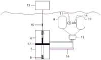
图2为本发明可控液压控制系统结构图。FIG. 2 is a structural diagram of the controllable hydraulic control system of the present invention.
图3为本发明电磁控制阀结构图。FIG. 3 is a structural diagram of the electromagnetic control valve of the present invention.
图中:1、振动浮子系统;2、可控液压系统;3、直线发电机系统;4、系统基座;5、锚泊系统;6、上液压室;7、下液压室;8、储能弹簧;9、第一液压缸;10、第二液压缸;11、液压泵;12、电磁控制阀;13、浮体;14、溢流阀;15、保护弹簧;16、液压油管路;17、活塞;18、第一电磁线圈;19、第二电磁线圈;20、第一排液口;21、压力口;22、第二排液口;23、第一接口;24、第二接口;25、阀芯。In the figure: 1. Vibration float system; 2. Controllable hydraulic system; 3. Linear generator system; 4. System base; 5. Mooring system; 6. Upper hydraulic chamber; 7. Lower hydraulic chamber; 8. Energy storage Spring; 9. First hydraulic cylinder; 10. Second hydraulic cylinder; 11. Hydraulic pump; 12. Electromagnetic control valve; 13. Floating body; 14. Relief valve; 15. Protection spring; 16. Hydraulic oil pipeline; 17. Piston; 18, the first solenoid coil; 19, the second solenoid coil; 20, the first liquid discharge port; 21, the pressure port; 22, the second liquid discharge port; 23, the first port; 24, the second port; 25 , valve core.
具体实施方式Detailed ways
需要说明的是,在不冲突的情况下,本发明中的实施例及实施例中的特征可以相互组合。下面将参考附图并结合实施例来详细说明本发明。It should be noted that the embodiments of the present invention and the features of the embodiments may be combined with each other under the condition of no conflict. The present invention will be described in detail below with reference to the accompanying drawings and in conjunction with the embodiments.
为使本发明实施例的目的、技术方案和优点更加清楚,下面将结合本发明实施例中的附图,对本发明实施例中的技术方案进行清楚、完整地描述,显然,所描述的实施例仅仅是本发明一部分实施例,而不是全部的实施例。以下对至少一个示例性实施例的描述实际上仅仅是说明性的,决不作为对本发明及其应用或使用的任何限制。基于本发明中的实施例,本领域普通技术人员在没有做出创造性劳动前提下所获得的所有其他实施例,都属于本发明保护的范围。In order to make the purposes, technical solutions and advantages of the embodiments of the present invention clearer, the technical solutions in the embodiments of the present invention will be clearly and completely described below with reference to the accompanying drawings in the embodiments of the present invention. Obviously, the described embodiments It is only a part of the embodiments of the present invention, but not all of the embodiments. The following description of at least one exemplary embodiment is merely illustrative in nature and is in no way intended to limit the invention, its application, or uses. Based on the embodiments of the present invention, all other embodiments obtained by those of ordinary skill in the art without creative efforts shall fall within the protection scope of the present invention.
需要注意的是,这里所使用的术语仅是为了描述具体实施方式,而非意图限制根据本发明的示例性实施方式。如在这里所使用的,除非上下文另外明确指出,否则单数形式也意图包括复数形式,此外,还应当理解的是,当在本说明书中使用术语“包含”和/或“包括”时,其指明存在特征、步骤、操作、器件、组件和/或它们的组合。It should be noted that the terminology used herein is for the purpose of describing specific embodiments only, and is not intended to limit the exemplary embodiments according to the present invention. As used herein, unless the context clearly dictates otherwise, the singular is intended to include the plural as well, furthermore, it is to be understood that when the terms "comprising" and/or "including" are used in this specification, it indicates that There are features, steps, operations, devices, components and/or combinations thereof.
除非另外具体说明,否则在这些实施例中阐述的部件和步骤的相对布置、数字表达式和数值不限制本发明的范围。同时,应当清楚,为了便于描述,附图中所示出的各个部分的尺寸并不是按照实际的比例关系绘制的。对于相关领域普通技术人员己知的技术、方法和设备可能不作详细讨论,但在适当情况下,所述技术、方法和设备应当被视为授权说明书的一部分。在这里示出和讨论的所有示例中,任向具体值应被解释为仅仅是示例性的,而不是作为限制。因此,示例性实施例的其它示例可以具有不同的值。应注意到:相似的标号和字母在下面的附图中表示类似项,因此,一旦某一项在一个附图中被定义,则在随后的附图中不需要对其进行进一步讨论。The relative arrangement of the components and steps, the numerical expressions and numerical values set forth in these embodiments do not limit the scope of the invention unless specifically stated otherwise. Meanwhile, it should be understood that, for convenience of description, the dimensions of various parts shown in the accompanying drawings are not drawn in an actual proportional relationship. Techniques, methods, and devices known to those of ordinary skill in the relevant art may not be discussed in detail, but where appropriate, such techniques, methods, and devices should be considered part of the authorized specification. In all examples shown and discussed herein, any specific values should be construed as illustrative only and not limiting. Accordingly, other examples of exemplary embodiments may have different values. It should be noted that like numerals and letters refer to like items in the following figures, so once an item is defined in one figure, it does not require further discussion in subsequent figures.
在本发明的描述中,需要理解的是,方位词如“前、后、上、下、左、右”、“横向、竖向、垂直、水平”和“顶、底”等所指示的方位或位置关系通常是基于附图所示的方位或位置关系,仅是为了便于描述本发明和简化描述,在未作相反说明的情况下,这些方位词并不指示和暗示所指的装置或元件必须具有特定的方位或者以特定的方位构造和操作,因此不能理解为对本发明保护范围的限制:方位词“内、外”是指相对于各部件本身的轮廓的内外。In the description of the present invention, it should be understood that the orientations indicated by orientation words such as "front, rear, top, bottom, left, right", "horizontal, vertical, vertical, horizontal" and "top, bottom" etc. Or the positional relationship is usually based on the orientation or positional relationship shown in the drawings, which is only for the convenience of describing the present invention and simplifying the description, and these orientation words do not indicate or imply the indicated device or element unless otherwise stated. It must have a specific orientation or be constructed and operated in a specific orientation, so it should not be construed as a limitation on the scope of protection of the present invention: the orientation words "inside and outside" refer to the inside and outside relative to the contour of each component itself.
为了便于描述,在这里可以使用空间相对术语,如“在……之上”、“在……上方”、“在……上表面”、“上面的”等,用来描述如在图中所示的一个器件或特征与其他器件或特征的空间位置关系。应当理解的是,空间相对术语旨在包含除了器件在图中所描述的方位之外的在使用或操作中的不同方位。例如,如果附图中的器件被倒置,则描述为“在其他器件或构造上方”或“在其他器件或构造之上”的器件之后将被定位为“在其他器件或构造下方”或“在其位器件或构造之下”。因而,示例性术语“在……上方”可以包括“在……上方”和“在……下方”两种方位。该器件也可以其他不同方式定位(旋转90度或处于其他方位),并且对这里所使用的空间相对描述作出相应解释。For ease of description, spatially relative terms, such as "on", "over", "on the surface", "above", etc., may be used herein to describe what is shown in the figures. The spatial positional relationship of one device or feature shown to other devices or features. It should be understood that spatially relative terms are intended to encompass different orientations of the device in use or operation in addition to the orientation depicted in the figures. For example, if the device in the figures is turned over, elements described as "above" or "over" other devices or features would then be oriented "below" or "over" the other devices or features under its device or structure". Thus, the exemplary term "above" can encompass both an orientation of "above" and "below." The device may also be otherwise oriented (rotated 90 degrees or at other orientations) and the spatially relative descriptions used herein interpreted accordingly.
此外,需要说明的是,使用“第一”、“第二”等词语来限定零部件,仅仅是为了便于对相应零部件进行区别,如没有另行声明,上述词语并没有特殊含义,因此不能理解为对本发明保护范围的限制。In addition, it should be noted that the use of words such as "first" and "second" to define components is only for the convenience of distinguishing corresponding components. Unless otherwise stated, the above words have no special meaning and therefore cannot be understood to limit the scope of protection of the present invention.
如图1所示,本发明提供了一种波浪能最大波能跟踪控制系统,基于利用可控液压系统2控制浮体上下震动的策略设计实现,基于搭建的系统,针对海况的不同情况,实现最大波能跟踪控制。采用直线发电机系统3作为波浪能核心采集机构,直接将波浪上下运动的机械能转化为电能,极大的提高了波浪能收集效率,同时针对海洋环境多变,波浪不规律本文设计可控液压系统2实现最大波能跟踪,优化波浪能采集系统。本发明具有环境适应性强,波能收集效率高等优势,可实现全天候的波浪能采集,为开发并高效利用波浪能发电提供了可能。As shown in Figure 1, the present invention provides a maximum wave energy tracking control system for wave energy, which is based on the strategy design and implementation of using the controllable
其具体方案如下:Its specific plan is as follows:
一种波浪能最大波能跟踪控制系统,包括:振动浮子系统1、可控液压系统2、直线发电机系统3以及锚泊系统4;可控液压系统2连接直线发电机系统3均安装在振动浮子系统1,且所述的振动浮子系统1连接锚泊系统4并将其与海底连接;直线发电机系统3外部还罩有用于保护圆筒型永磁同步直线电机的系统基座4。A wave energy maximum wave energy tracking control system, comprising: a vibrating
实施例1Example 1
可控液压系统2采用液压油作为传递能量的工作介质,该系统由信号控制部分与液压动力部分构成。信号控制部分通过传感器测得的波浪垂直方向的速度,将传感器信号传递给中央控制器,执行器为液压泵11的转速与电磁控制阀12的状态;液压动力部分根据信号控制部分传送的信号提供给液压泵11、电磁控制阀12,液压泵11控制液压油的流量大小,电磁控制阀控制12液压油的流动方向。经过液压系统的补充,定子运动与波浪能上下起伏运动一致,形成共振,实现波浪能的最大吸收,当然可控液压系统2并不是实时改变,根据海洋环境为中央控制器设置不同阈值,以实现更好的环境适应性。The controllable
如图2所示,可控液压系统2包括电磁控制阀12、第一液压缸9、第二液压缸10、液压油管路16、液压泵11、储能弹簧8、浮体13以及溢流阀14;浮体13通过绳子和保护弹簧15连接所述直线发电机系统3,直线发电机系统3中的动子上下连接储能弹簧8,直线发电机系统3中的定子由活塞17分为上液压室6和下液压室7,上液压室6和下液压室7分别连接液压油管路16且通过电磁控制阀12连接第一液压缸9和第二液压缸10,第一液压缸9和第二液压缸10之间连接有液压泵11和溢流阀14。当需要向下的控制力时,液压油由下液压室7到第二液压缸10,第一液压缸9到上液压室6,此时上部压强大于下部压强。当需要向上的力时,液压油由上液压室6到第二液压缸10,第一液压缸9到上液压室6,此时下部压强大于上部压强。As shown in FIG. 2 , the controllable
设pa,pb,p1,p2分别为上液压室6、下液压室7、第一液压缸9、第二液压缸10的压强,当活塞向上运动时pa>p1,pb<p2,液压油管中的液体体积流率为q=Scdx/dt,其中Sc为液压油管横截面积,x为活塞向上运动量。故:Let pa , pb , p1 , and p2 be the pressures of the upper

其中Ku为由摩擦引起的压力损耗系数,I为液体惯性系数。whereKu is the coefficient of pressure loss caused by friction, and I is the coefficient of inertia of the liquid.
第一液压缸9与第二液压缸10中的液压油由液压泵11驱动,液体体积流量与液压泵11电机转速成正比,即The hydraulic oil in the first
qm=λNqm =λN
其中,λ为和电机几何结构相关的常数,N为电机转速。Among them, λ is a constant related to the motor geometry, and N is the motor speed.
将测得的波浪竖直方向速度的变化带入上述公式,可得到液压泵11电机的转速的变化,通过液压泵11转速的变化可控制活塞17的上下运动,实现浮体13与波浪能共振,得到最大波浪能的可控吸收。Bringing the change of the measured wave speed in the vertical direction into the above formula, the change of the rotational speed of the motor of the
根据信号控制装置处理的结果,系统将为电磁控制阀12、液压泵11实时供电,通过中央控制器控制液压泵11的转速以控制流入上液压室6、下液压室7的液压油的流速,实时控制活塞17上下运动的速度,使活塞17上下运动速度与波浪竖直方向速度相同,即产生共振。控制电磁控制阀12两侧的供电情况,可以改变上下液压室液压油的流向,为实现共振提供油路交换的可能。在液压管路压力较高时,液压油可通过溢流阀13流入液压缸8或9,从而液压油管路的压力防止炸缸,保证液压系统安全稳定的工作。According to the result processed by the signal control device, the system will supply power to the
实施例2Example 2
电磁控制阀12包括第一电磁线圈18、第二电磁线圈19、第一排液口20、第二排液口22、压力口21、第一接口23、第二接口24以及阀芯25;压力口21为机制口,第一接口23连接上液压室6,第二接口24连接下液压室7,第一排液口20连接第一液压缸9,第二排液口22连接第二液压缸10,通过可控液压系统控制2第一电磁线圈18和第二电磁线圈19的通电,从而控制液压油的流向,进而推动活塞17的上下运动。The
具体执行如下,当活塞17欲向下运动时,第一电磁线圈18通电,第二电磁线圈19不通电,阀芯25向左动,第一排液口20与第一接口23接通,第二接口24与压力口21接通,此时压力口21与第二排液口22相连。第一液压缸9中的液压油从第一排液口20流入经过第一接口23,流进上液压室6,下液压室7中的液压油经过压力口21流入第二液压缸10;当活塞17欲向上运动时,第一电磁线圈18不通电,第二电磁线圈19通电,阀芯25向右移动,压力口21与第一接口23接通,第二排液口22与第二接口24接通,此时压力口21与第一排液口20相连。第一液压缸9中液压油流入下液压室7,上液压室6中的液压油流入第二液压缸10中。The specific implementation is as follows: when the
通过上述过程的阀内液压油路的交换,实现了液压油推动活塞17上下运动,通过控制即可实现浮子与波浪的共振。Through the exchange of the hydraulic oil circuit in the valve in the above process, it is realized that the hydraulic oil pushes the
实施例3Example 3
直线发电机系统3为一12槽1l极的圆筒型永磁同步直线电机,其包括动子、定子、永磁体和三相线圈,永磁体贴敷在动子表面,三相线圈埋设在定子槽内。当动子随着波浪做上下往复运动时,会与定子产生相对运动,从而在定子绕组输出端产生感应电动势,实现了波浪能到电能的转换。12槽1l极的圆筒型永磁同步直线电机结构简单,可实现波浪能到电能的一级转换,有效提高波浪能的转换效率。The
实施例4Example 4
振动浮子系统1为一圆柱形漂浮体,其内部承载有整流变换系统、蓄电池组、北斗定位系统模块、信号发生器接收器以及气象监测设备。The vibrating
实施例5Example 5
锚泊系统5主要由锚链、锚和若干个沉块组成,采用垂向锚泊系统固定波浪能最大波能跟踪控制系统中的发电设备,为波浪能发电系统提供相对稳定的工作平台环境。The
实施例6Example 6
波浪能最大波能跟踪控制系统还包括小型太阳能发电系统,小型太阳能发电系统安装在所述振动浮子系统1。将圆柱形漂浮体与太阳能板相结合,使太阳能板始终漂浮在海面上,充分获得太阳能并将太阳能转化成可用的电能,将电能储存在蓄电池中,供给液压泵11使用。The wave energy maximum wave energy tracking control system further includes a small solar power generation system, and the small solar power generation system is installed in the vibrating
本发明的主要工作原理如下:The main working principle of the present invention is as follows:
当波浪运动时,波浪带动圆柱形漂浮体运动,将波浪上下方向运动直接转化为电能,当波浪较大超过设计最大量程时,通过储能弹簧8进行机械储能;直线发电机系统3产生的电能经过电能处理装置经过一系列整流、斩波后存储在蓄电池中备用;可控液压系统2通过传感器测得的波浪垂直方向的速度,将传感器信号传递给中央控制器,且根据传送的信号提供给液压泵11、电磁控制阀12,液压泵11控制液压油的流量大小,电磁控制阀12控制液压油的流动方向,经过可控液压系统2的补充,定子运动与波浪能上下起伏运动一致,形成共振,实现波浪能的最大吸收。When the wave moves, the wave drives the movement of the cylindrical floating body, and directly converts the upward and downward movement of the wave into electrical energy. When the wave is larger than the designed maximum range, the
需要注意的是,本发明并不是实时接入振动浮子系统1,而是由中央控制器控制是否接入,中央处理器具有一定的阈值,中央控制器由波浪速度传感器控制,即波浪达到一定的波速时可控液压系统2才接入,这样使液压控制系统具有更好的环境适用性,同时可控液压系统2仅仅是振动浮子系统1的补充,直线发电机系统3的驱动主要由波浪完成。It should be noted that the present invention is not connected to the vibrating
最后应说明的是:以上各实施例仅用以说明本发明的技术方案,而非对其限制;尽管参照前述各实施例对本发明进行了详细的说明,本领域的普通技术人员应当理解:其依然可以对前述各实施例所记载的技术方案进行修改,或者对其中部分或者全部技术特征进行等同替换;而这些修改或者替换,并不使相应技术方案的本质脱离本发明各实施例技术方案的范围。Finally, it should be noted that the above embodiments are only used to illustrate the technical solutions of the present invention, but not to limit them; although the present invention has been described in detail with reference to the foregoing embodiments, those of ordinary skill in the art should understand that: The technical solutions described in the foregoing embodiments can still be modified, or some or all of the technical features thereof can be equivalently replaced; and these modifications or replacements do not make the essence of the corresponding technical solutions deviate from the technical solutions of the embodiments of the present invention. scope.
Claims (7)
Priority Applications (1)
| Application Number | Priority Date | Filing Date | Title |
|---|---|---|---|
| CN201910780869.5ACN110454319B (en) | 2019-08-22 | 2019-08-22 | A wave energy maximum wave energy tracking control system |
Applications Claiming Priority (1)
| Application Number | Priority Date | Filing Date | Title |
|---|---|---|---|
| CN201910780869.5ACN110454319B (en) | 2019-08-22 | 2019-08-22 | A wave energy maximum wave energy tracking control system |
Publications (2)
| Publication Number | Publication Date |
|---|---|
| CN110454319A CN110454319A (en) | 2019-11-15 |
| CN110454319Btrue CN110454319B (en) | 2020-11-27 |
Family
ID=68488692
Family Applications (1)
| Application Number | Title | Priority Date | Filing Date |
|---|---|---|---|
| CN201910780869.5AActiveCN110454319B (en) | 2019-08-22 | 2019-08-22 | A wave energy maximum wave energy tracking control system |
Country Status (1)
| Country | Link |
|---|---|
| CN (1) | CN110454319B (en) |
Families Citing this family (7)
| Publication number | Priority date | Publication date | Assignee | Title |
|---|---|---|---|---|
| CN111911608B (en)* | 2020-07-13 | 2025-04-01 | 北京中科电气高技术有限公司 | Ring magnetic rod hydraulic displacement transmission device for solar tracking system |
| CN113335467A (en)* | 2021-05-28 | 2021-09-03 | 哈尔滨工业大学(深圳) | Ocean floating platform based on wave energy and solar energy combined power generation |
| CN113623121B (en)* | 2021-09-10 | 2023-03-14 | 大连海事大学 | Wave current coupling underwater power generation device for marine lamp buoy |
| CN114320715B (en)* | 2021-12-31 | 2023-05-02 | 同济大学 | Inertial-energy-point vibration absorption type wave energy power generation system |
| CN115042942B (en)* | 2022-06-17 | 2023-11-24 | 天津大学 | Multi-float detection device suitable for AUV (autonomous Underwater vehicle) carrying |
| CN117469075B (en)* | 2023-10-31 | 2024-05-14 | 广东海洋大学 | Wave energy pressure amplifying device and ocean pasture feeding system and method |
| US12203440B1 (en) | 2023-10-31 | 2025-01-21 | Guangdong Ocean University | Wave energy pressure amplification device and marine ranching feeding system and method |
Family Cites Families (6)
| Publication number | Priority date | Publication date | Assignee | Title |
|---|---|---|---|---|
| US20110121572A1 (en)* | 2009-11-20 | 2011-05-26 | Leonid Levchets | Wave Motion Power Generator |
| US9435317B2 (en)* | 2010-06-23 | 2016-09-06 | Wave Energy Conversion Corporation of America | System and method for renewable electrical power production using wave energy |
| CN102506005B (en)* | 2011-11-17 | 2013-12-18 | 中国水利水电科学研究院 | Device and method for parametric resonance-based float-hydraulic wave energy power generation |
| CN104061115B (en)* | 2014-07-03 | 2018-12-11 | 国家海洋技术中心 | A kind of more float wave energy generating sets of floatation type |
| CN205779449U (en)* | 2016-05-17 | 2016-12-07 | 中国海洋大学 | Combined oscillating floater wave energy generating set and TT&C system thereof |
| CN206164287U (en)* | 2016-11-10 | 2017-05-10 | 三峡大学 | Wave energy power generation facility based on linear generator |
- 2019
- 2019-08-22CNCN201910780869.5Apatent/CN110454319B/enactiveActive
Also Published As
| Publication number | Publication date |
|---|---|
| CN110454319A (en) | 2019-11-15 |
Similar Documents
| Publication | Publication Date | Title |
|---|---|---|
| CN110454319B (en) | A wave energy maximum wave energy tracking control system | |
| Li et al. | Towards self-powered technique in underwater robots via a high-efficiency electromagnetic transducer with circularly abrupt magnetic flux density change | |
| KR101521882B1 (en) | Tention mooring system | |
| EP1423605B1 (en) | Apparatus for wave energy conversion using a flot with execess buoyancy | |
| KR101604780B1 (en) | Wave power generator | |
| KR101386699B1 (en) | Solar-wave-wind combined mooring power generation unit and system | |
| EP2058222A1 (en) | Special platform for generating electricity using solar energy | |
| CN107288808B (en) | Wave energy and solar energy complementary drifting buoy self-power device | |
| CN106351781B (en) | A kind of submarine navigation device inductive charging system based on wave-light energy complementary power generation | |
| KR20100091860A (en) | Self generation light buoy in parallel with wave power and solar cell | |
| CN106050540A (en) | Multi-float-rod wave power generation device | |
| EP4328445A1 (en) | Offshore floater system | |
| CN111532382A (en) | Internal inertia body type wave energy power supply ocean monitoring buoy | |
| US12122489B1 (en) | Ocean observation platform integrated with highly reliable wave energy generation mechanism and working method thereof | |
| CN104131944A (en) | Marine ocean wave generating device outputting constant power | |
| CN111997816A (en) | A ship-borne impact-type turbulence-driven wave generator | |
| US20190085817A1 (en) | Energy conversion device | |
| CN109178261B (en) | Self-generating underwater detection robot based on oscillation floating pendulum and application thereof | |
| CN116985959A (en) | Argo buoy with water wheel energy collection system | |
| CN103587654A (en) | Ocean wave energy self-powered cyclic detection ecobuoy | |
| AU2013204537B2 (en) | Electricity generating appparatus | |
| CN110513239A (en) | A self-powered device for ocean buoys based on wave power generation | |
| CN108953044A (en) | A kind of multifunction floating mark based on the coupling self power generation of multi-source energy supply type | |
| CN111422308A (en) | Wave energy and solar energy combined power supply buoy and power supply method | |
| CN117842293B (en) | Offshore charging system |
Legal Events
| Date | Code | Title | Description |
|---|---|---|---|
| PB01 | Publication | ||
| PB01 | Publication | ||
| SE01 | Entry into force of request for substantive examination | ||
| SE01 | Entry into force of request for substantive examination | ||
| GR01 | Patent grant | ||
| GR01 | Patent grant |