CN110430930B - Filter Assemblies with Top Ribbed Internal Filter Elements - Google Patents
Filter Assemblies with Top Ribbed Internal Filter ElementsDownload PDFInfo
- Publication number
- CN110430930B CN110430930BCN201880018960.7ACN201880018960ACN110430930BCN 110430930 BCN110430930 BCN 110430930BCN 201880018960 ACN201880018960 ACN 201880018960ACN 110430930 BCN110430930 BCN 110430930B
- Authority
- CN
- China
- Prior art keywords
- filter element
- end plate
- outer filter
- rib
- filter
- Prior art date
- Legal status (The legal status is an assumption and is not a legal conclusion. Google has not performed a legal analysis and makes no representation as to the accuracy of the status listed.)
- Active
Links
Images


Classifications
- B—PERFORMING OPERATIONS; TRANSPORTING
- B01—PHYSICAL OR CHEMICAL PROCESSES OR APPARATUS IN GENERAL
- B01D—SEPARATION
- B01D29/00—Filters with filtering elements stationary during filtration, e.g. pressure or suction filters, not covered by groups B01D24/00 - B01D27/00; Filtering elements therefor
- B01D29/50—Filters with filtering elements stationary during filtration, e.g. pressure or suction filters, not covered by groups B01D24/00 - B01D27/00; Filtering elements therefor with multiple filtering elements, characterised by their mutual disposition
- B01D29/56—Filters with filtering elements stationary during filtration, e.g. pressure or suction filters, not covered by groups B01D24/00 - B01D27/00; Filtering elements therefor with multiple filtering elements, characterised by their mutual disposition in series connection
- B01D29/58—Filters with filtering elements stationary during filtration, e.g. pressure or suction filters, not covered by groups B01D24/00 - B01D27/00; Filtering elements therefor with multiple filtering elements, characterised by their mutual disposition in series connection arranged concentrically or coaxially
- B—PERFORMING OPERATIONS; TRANSPORTING
- B01—PHYSICAL OR CHEMICAL PROCESSES OR APPARATUS IN GENERAL
- B01D—SEPARATION
- B01D29/00—Filters with filtering elements stationary during filtration, e.g. pressure or suction filters, not covered by groups B01D24/00 - B01D27/00; Filtering elements therefor
- B01D29/11—Filters with filtering elements stationary during filtration, e.g. pressure or suction filters, not covered by groups B01D24/00 - B01D27/00; Filtering elements therefor with bag, cage, hose, tube, sleeve or like filtering elements
- B01D29/13—Supported filter elements
- B01D29/15—Supported filter elements arranged for inward flow filtration
- B—PERFORMING OPERATIONS; TRANSPORTING
- B01—PHYSICAL OR CHEMICAL PROCESSES OR APPARATUS IN GENERAL
- B01D—SEPARATION
- B01D35/00—Filtering devices having features not specifically covered by groups B01D24/00 - B01D33/00, or for applications not specifically covered by groups B01D24/00 - B01D33/00; Auxiliary devices for filtration; Filter housing constructions
- B01D35/14—Safety devices specially adapted for filtration; Devices for indicating clogging
- B01D35/153—Anti-leakage or anti-return valves
- B—PERFORMING OPERATIONS; TRANSPORTING
- B01—PHYSICAL OR CHEMICAL PROCESSES OR APPARATUS IN GENERAL
- B01D—SEPARATION
- B01D35/00—Filtering devices having features not specifically covered by groups B01D24/00 - B01D33/00, or for applications not specifically covered by groups B01D24/00 - B01D33/00; Auxiliary devices for filtration; Filter housing constructions
- B01D35/30—Filter housing constructions
- B01D35/306—Filter mounting adapter
- B—PERFORMING OPERATIONS; TRANSPORTING
- B01—PHYSICAL OR CHEMICAL PROCESSES OR APPARATUS IN GENERAL
- B01D—SEPARATION
- B01D36/00—Filter circuits or combinations of filters with other separating devices
- B01D36/003—Filters in combination with devices for the removal of liquids
- F—MECHANICAL ENGINEERING; LIGHTING; HEATING; WEAPONS; BLASTING
- F02—COMBUSTION ENGINES; HOT-GAS OR COMBUSTION-PRODUCT ENGINE PLANTS
- F02M—SUPPLYING COMBUSTION ENGINES IN GENERAL WITH COMBUSTIBLE MIXTURES OR CONSTITUENTS THEREOF
- F02M37/00—Apparatus or systems for feeding liquid fuel from storage containers to carburettors or fuel-injection apparatus; Arrangements for purifying liquid fuel specially adapted for, or arranged on, internal-combustion engines
- F02M37/22—Arrangements for purifying liquid fuel specially adapted for, or arranged on, internal-combustion engines, e.g. arrangements in the feeding system
- F02M37/32—Arrangements for purifying liquid fuel specially adapted for, or arranged on, internal-combustion engines, e.g. arrangements in the feeding system characterised by filters or filter arrangements
- F02M37/42—Installation or removal of filters
- F—MECHANICAL ENGINEERING; LIGHTING; HEATING; WEAPONS; BLASTING
- F02—COMBUSTION ENGINES; HOT-GAS OR COMBUSTION-PRODUCT ENGINE PLANTS
- F02M—SUPPLYING COMBUSTION ENGINES IN GENERAL WITH COMBUSTIBLE MIXTURES OR CONSTITUENTS THEREOF
- F02M37/00—Apparatus or systems for feeding liquid fuel from storage containers to carburettors or fuel-injection apparatus; Arrangements for purifying liquid fuel specially adapted for, or arranged on, internal-combustion engines
- F02M37/22—Arrangements for purifying liquid fuel specially adapted for, or arranged on, internal-combustion engines, e.g. arrangements in the feeding system
- F02M37/32—Arrangements for purifying liquid fuel specially adapted for, or arranged on, internal-combustion engines, e.g. arrangements in the feeding system characterised by filters or filter arrangements
- F02M37/48—Filters structurally associated with fuel valves
- B—PERFORMING OPERATIONS; TRANSPORTING
- B01—PHYSICAL OR CHEMICAL PROCESSES OR APPARATUS IN GENERAL
- B01D—SEPARATION
- B01D2201/00—Details relating to filtering apparatus
- B01D2201/04—Supports for the filtering elements
- B—PERFORMING OPERATIONS; TRANSPORTING
- B01—PHYSICAL OR CHEMICAL PROCESSES OR APPARATUS IN GENERAL
- B01D—SEPARATION
- B01D2201/00—Details relating to filtering apparatus
- B01D2201/29—Filter cartridge constructions
- B01D2201/291—End caps
- B—PERFORMING OPERATIONS; TRANSPORTING
- B01—PHYSICAL OR CHEMICAL PROCESSES OR APPARATUS IN GENERAL
- B01D—SEPARATION
- B01D2201/00—Details relating to filtering apparatus
- B01D2201/29—Filter cartridge constructions
- B01D2201/291—End caps
- B01D2201/295—End caps with projections extending in a radial outward direction, e.g. for use as a guide, spacing means
- F—MECHANICAL ENGINEERING; LIGHTING; HEATING; WEAPONS; BLASTING
- F02—COMBUSTION ENGINES; HOT-GAS OR COMBUSTION-PRODUCT ENGINE PLANTS
- F02M—SUPPLYING COMBUSTION ENGINES IN GENERAL WITH COMBUSTIBLE MIXTURES OR CONSTITUENTS THEREOF
- F02M37/00—Apparatus or systems for feeding liquid fuel from storage containers to carburettors or fuel-injection apparatus; Arrangements for purifying liquid fuel specially adapted for, or arranged on, internal-combustion engines
- F02M37/22—Arrangements for purifying liquid fuel specially adapted for, or arranged on, internal-combustion engines, e.g. arrangements in the feeding system
- F02M37/24—Arrangements for purifying liquid fuel specially adapted for, or arranged on, internal-combustion engines, e.g. arrangements in the feeding system characterised by water separating means
- F—MECHANICAL ENGINEERING; LIGHTING; HEATING; WEAPONS; BLASTING
- F02—COMBUSTION ENGINES; HOT-GAS OR COMBUSTION-PRODUCT ENGINE PLANTS
- F02M—SUPPLYING COMBUSTION ENGINES IN GENERAL WITH COMBUSTIBLE MIXTURES OR CONSTITUENTS THEREOF
- F02M37/00—Apparatus or systems for feeding liquid fuel from storage containers to carburettors or fuel-injection apparatus; Arrangements for purifying liquid fuel specially adapted for, or arranged on, internal-combustion engines
- F02M37/22—Arrangements for purifying liquid fuel specially adapted for, or arranged on, internal-combustion engines, e.g. arrangements in the feeding system
- F02M37/32—Arrangements for purifying liquid fuel specially adapted for, or arranged on, internal-combustion engines, e.g. arrangements in the feeding system characterised by filters or filter arrangements
- F02M37/34—Arrangements for purifying liquid fuel specially adapted for, or arranged on, internal-combustion engines, e.g. arrangements in the feeding system characterised by filters or filter arrangements by the filter structure, e.g. honeycomb, mesh or fibrous
Landscapes
- Chemical & Material Sciences (AREA)
- Engineering & Computer Science (AREA)
- Chemical Kinetics & Catalysis (AREA)
- Combustion & Propulsion (AREA)
- Mechanical Engineering (AREA)
- General Engineering & Computer Science (AREA)
- Lubrication Details And Ventilation Of Internal Combustion Engines (AREA)
- Filtering Of Dispersed Particles In Gases (AREA)
- Prostheses (AREA)
Abstract
Translated fromChinese
Description
Translated fromChinese相关专利申请的交叉引用Cross references to related patent applications
本申请要求2017年3月20日提交的美国临时专利申请No.62/473,687的优先权和权益,其全部内容通过引用并入本文。This application claims priority to and benefit of U.S. Provisional Patent Application No. 62/473,687, filed March 20, 2017, the entire contents of which are incorporated herein by reference.
技术领域technical field
本发明一般涉及与内燃机等使用的过滤器组件。The present invention relates generally to filter assemblies for use with internal combustion engines and the like.
背景技术Background technique
过滤器组件可用于过滤各种不同的流体。为了过滤流体,许多传统的过滤器组件包括外部过滤器元件和内部过滤器元件。内部过滤器元件位于外部过滤器元件内。内部过滤器元件可以具有内部顶端板,该内部顶端板具有在内部过滤器元件的纵向方向并且与内部顶端板的顶部表面垂直的方向上垂直延伸的腿部。腿部可以彼此间隔开,使得腿部不会围绕内部顶端板的一部分连续延伸。Filter assemblies are available for filtering a variety of different fluids. To filter fluids, many conventional filter assemblies include an outer filter element and an inner filter element. The inner filter element is located within the outer filter element. The inner filter element may have an inner top end plate with legs extending vertically in the longitudinal direction of the inner filter element and in a direction perpendicular to the top surface of the inner top end plate. The legs may be spaced apart from each other such that the legs do not extend continuously around a portion of the inner top end panel.
在这样的布置中,在将内部过滤器元件安装在外部过滤器元件内时会出现许多问题,使得安装变得困难。例如,当内部过滤器元件被操作者或压力设备推动并旋转通过外部元件的内部时,内部过滤器元件可以不遵循外部过滤器元件的纵向轴线,而是可能在安装期间相对于外部过滤器元件的纵向轴线在外部过滤器元件内在各种不同方向上成角度。这可能导致内部顶端板上的腿部不正确地接触外部过滤器元件的各个部分并且可能卡在外部过滤器元件内。In such an arrangement, a number of problems arise when installing the inner filter element within the outer filter element, making installation difficult. For example, when the inner filter element is pushed and rotated through the interior of the outer element by an operator or pressure equipment, the inner filter element may not follow the longitudinal axis of the outer filter element, but may be relative to the outer filter element during installation. The longitudinal axis of is angled in various directions within the outer filter element. This can cause the legs on the inner top plate to improperly contact parts of the outer filter element and possibly get stuck within the outer filter element.
作为不正确接触的一个示例,代替围绕止回阀保持器延伸,腿部可以“撞到”并且触底外部过滤器元件的外部顶端板上的止回阀保持器或者被卡住在外部过滤器元件的外部顶端板上的止回阀保持器上,这防止了内部过滤器元件完全插入外部过滤器元件中。另外,内部过滤器元件的内部顶端板上的腿部可能卡在或夹在外部过滤器元件的各种其他部件上,例如中心管和/或聚结包裹物。更进一步地,内部过滤器元件的内部顶端板上的腿部可能在安装期间夹住外部过滤器元件的聚结包裹物的部分,这在聚结包裹物中形成孔并且损坏外部过滤器元件,从而对过滤器组件的过滤性能和燃油水分离效率产生负面影响。As an example of incorrect contact, instead of extending around the check valve retainer, the leg could "hit" and bottom out the check valve retainer on the outer top plate of the outer filter element or get stuck on the outer filter This prevents the inner filter element from being fully inserted into the outer filter element. Additionally, the legs on the inner top plate of the inner filter element may snap or clip onto various other components of the outer filter element, such as the center tube and/or the coalescing wrap. Still further, the legs on the inner top plate of the inner filter element may pinch portions of the coalescing wrap of the outer filter element during installation, which creates holes in the coalescing wrap and damages the outer filter element, This can negatively affect the filtration performance and fuel-water separation efficiency of the filter assembly.
每次内部过滤器元件卡在外部过滤器元件上时,操作者可能必须从外部过滤器元件移除内部过滤器元件并开始安装过程。内部过滤器元件通常不能一次安装在外部过滤器元件内,而是可能需要在安装期间多次重新调整或重新定位(每次都可能损坏外部过滤器元件),直到内部过滤器元件正确安装在外部过滤器元件内。这种安装过程增加了产品组装周期时间,这增加了劳动力和管理成本,因此也增加了产品成本。因此,为了将内部过滤器元件安装在传统过滤器组件的外部过滤器元件内的正确位置,需要额外的时间、精力和金钱。Each time the inner filter element becomes stuck on the outer filter element, the operator may have to remove the inner filter element from the outer filter element and begin the installation process. The inner filter element usually cannot be installed once inside the outer filter element, but instead may need to be readjusted or repositioned several times during installation (each time potentially damaging the outer filter element) until the inner filter element is properly installed outside inside the filter element. This installation process increases product assembly cycle time, which increases labor and administrative costs, and therefore increases product cost. Therefore, additional time, effort and money are required to install the inner filter element in the correct position within the outer filter element of a conventional filter assembly.
发明内容Contents of the invention
各种实施例提供了一种过滤器组件,其包括壳体、外部过滤器元件和内部过滤器元件。外部过滤器元件可定位在壳体内并包括外部过滤介质。内部过滤器元件可定位在外部过滤器元件内并且包括内部过滤介质、介质支撑结构、内部顶端板和内部底端板。内部顶端板包括顶部肋,顶部肋围绕内部顶端板的顶表面的一部分连续延伸。顶部肋在组装期间将内部过滤器元件引导到外部过滤器元件内和内部。Various embodiments provide a filter assembly that includes a housing, an outer filter element, and an inner filter element. An outer filter element is positionable within the housing and includes outer filter media. The inner filter element is positionable within the outer filter element and includes an inner filter media, a media support structure, an inner top end plate, and an inner bottom end plate. The inner top end panel includes a top rib extending continuously around a portion of the top surface of the inner top end panel. The top rib guides the inner filter element into and into the outer filter element during assembly.
各种其他实施例提供了可定位在过滤器组件的外部过滤器元件内的内部过滤器元件。内部过滤器元件包括内部过滤介质、介质支撑结构、内部顶端板和内部底端板。内部顶端板包括顶部肋,顶部肋围绕内部顶端板的顶表面的一部分连续延伸。顶部肋在组装期间将内部过滤器元件引导到外部过滤器元件内和内部。Various other embodiments provide an inner filter element positionable within an outer filter element of a filter assembly. The inner filter element includes an inner filter media, a media support structure, an inner top end plate, and an inner bottom end plate. The inner top end panel includes a top rib extending continuously around a portion of the top surface of the inner top end panel. The top rib guides the inner filter element into and into the outer filter element during assembly.
各种其他实施例提供了组装过滤器组件的方法。该方法包括将包括内部过滤介质的内部过滤器元件定位在外部过滤器元件的外部过滤介质下方,插入内部过滤器元件的内部顶端板的顶部肋,随后插入内部过滤器元件的内部过滤介质在外部过滤器元件的外部过滤介质中,将内部过滤器元件的内部底端板附接到外部过滤器元件的外部底端板上。内部过滤器元件的内部顶端板的顶部肋围绕内部顶端板的顶表面的一部分连续地延伸。Various other embodiments provide methods of assembling filter assemblies. The method includes positioning an inner filter element comprising an inner filter media below the outer filter media of the outer filter element, inserting a top rib of an inner top end plate of the inner filter element, and subsequently inserting the inner filter media of the inner filter element outside In the outer filter media of the filter element, the inner bottom end plate of the inner filter element is attached to the outer bottom end plate of the outer filter element. The top rib of the inner top end plate of the inner filter element extends continuously around a portion of the top surface of the inner top end plate.
从以下结合附图的详细描述,这些和其他特征(包括但不限于保持特征和/或观察特征)以及其操作的组织和方式将变得显而易见,其中相同的元件在下面描述的几个附图中具有相同的标号。These and other features (including but not limited to holding features and/or viewing features), as well as the organization and manner of operation thereof, will become apparent from the following detailed description when taken in conjunction with the accompanying drawings, wherein like elements are described in the several figures below have the same label.
附图说明Description of drawings
图1A是根据一个实施例的过滤器组件的透视图。Figure 1A is a perspective view of a filter assembly according to one embodiment.
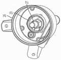
图1B是图1A的过滤器组件的壳体的下部的俯视透视图。FIG. 1B is a top perspective view of a lower portion of the housing of the filter assembly of FIG. 1A .
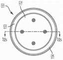
图1C是图1A的过滤器组件的壳体的下部的俯视图。Figure 1C is a top view of the lower portion of the housing of the filter assembly of Figure 1A.
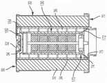
图2A是根据一个实施例的过滤器组件的过滤器组件的侧视图。Figure 2A is a side view of a filter assembly of a filter assembly according to one embodiment.
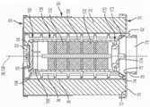
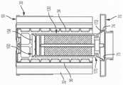
图2B是图2A的截面2B-2B的剖视图。Figure 2B is a cross-sectional view of
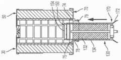
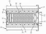
图2C是图2A的另一剖视图。Fig. 2C is another cross-sectional view of Fig. 2A.
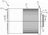
图3A是根据一个实施例的外部过滤器元件的透视图。Figure 3A is a perspective view of an outer filter element according to one embodiment.
图3B是图3A的外部过滤器元件的侧视图,其中内部过滤器元件安装在外部过滤器元件内。3B is a side view of the outer filter element of FIG. 3A with the inner filter element mounted within the outer filter element.
图3C是图3A的外部过滤器元件的俯视图。Figure 3C is a top view of the outer filter element of Figure 3A.
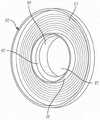
图4A是图3A的外部过滤器元件的外部底端板的俯视透视图。4A is a top perspective view of the outer bottom end plate of the outer filter element of FIG. 3A.
图4B是图4A的外部底端板的仰视透视图。Figure 4B is a bottom perspective view of the outer bottom end panel of Figure 4A.
图4C是图4A的外部底端板的剖视图。4C is a cross-sectional view of the outer bottom end plate of FIG. 4A.
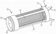
图5A是根据一个实施例的内部过滤器元件的透视图。Figure 5A is a perspective view of an internal filter element according to one embodiment.
图5B是图5A的内部过滤器元件的前视图。Figure 5B is a front view of the inner filter element of Figure 5A.
图5C是图5A的内部过滤器元件的剖视图。Figure 5C is a cross-sectional view of the inner filter element of Figure 5A.
图5D是根据另一实施例的内部过滤器元件的剖视图。Figure 5D is a cross-sectional view of an inner filter element according to another embodiment.
图6A是图5A的内部过滤器元件的内部顶端板的俯视透视图。6A is a top perspective view of the inner top end plate of the inner filter element of FIG. 5A.
图6B是图6A的内部顶端板的俯视透视图。6B is a top perspective view of the inner top end plate of FIG. 6A.
图6C是图6A的内部顶端板的仰视图。6C is a bottom view of the inner top end plate of FIG. 6A.
图6D是图6A的内部顶端板的俯视图。6D is a top view of the inner top end plate of FIG. 6A.
图6E是图6A的内部顶端板的侧视图。6E is a side view of the inner top end plate of FIG. 6A.
图6F是图6D的截面6F-6F的剖视图。Figure 6F is a cross-sectional view of
图7A是图5A的内部过滤器元件的一部分的剖视图。7A is a cross-sectional view of a portion of the inner filter element of FIG. 5A.
图7B是图5A的内部过滤器元件的一部分的剖视图。7B is a cross-sectional view of a portion of the inner filter element of FIG. 5A.
图8A是根据一个实施例的内部过滤器元件和外部过滤器元件对准的透视图。Figure 8A is a perspective view of the alignment of the inner and outer filter elements according to one embodiment.
图8B是内部过滤器元件被移动到图8A的外部过滤器元件中的剖视图。Figure 8B is a cross-sectional view of the inner filter element moved into the outer filter element of Figure 8A.
图8C是图3B的截面8C-8C的剖视图。Figure 8C is a cross-sectional view of
图9A-9D是根据一个实施例安装在外部过滤器元件内的内部过滤器元件的剖视图。9A-9D are cross-sectional views of an inner filter element installed within an outer filter element according to one embodiment.
图10A-10C是根据图9A-9D中所示的实施例的内部过滤器元件安装在外部过滤器元件内的剖视图。10A-10C are cross-sectional views of an inner filter element installed within an outer filter element according to the embodiment shown in FIGS. 9A-9D.
图11A-11C是根据另一实施例的安装在外部过滤器元件内的内部过滤器元件的剖视图。11A-11C are cross-sectional views of an inner filter element installed within an outer filter element according to another embodiment.
图12A-12C是根据图11A-11C中所示的实施例的内部过滤器元件安装在外部过滤器元件内的剖视图。12A-12C are cross-sectional views of an inner filter element installed within an outer filter element according to the embodiment shown in FIGS. 11A-11C.
图13是安装在外部过滤器元件内的内部过滤器元件的一部分的剖视图。Figure 13 is a cross-sectional view of a portion of an inner filter element installed within an outer filter element.
具体实施方式Detailed ways
总体上参考附图,本文公开的各种实施例涉及过滤器组件,其包括过滤器壳体、外部过滤器元件和内部过滤器元件。内部过滤器元件定位在外部过滤器元件内并且包括具有顶部肋的内部顶端板。内部过滤器元件的顶部肋便于将内部过滤器元件正确地安装到外部过滤器元件中,这确保了高质量的过滤器组件并且还减少了制造周期时间和生产和组装时间,从而降低了产品成本。Referring generally to the drawings, various embodiments disclosed herein relate to a filter assembly that includes a filter housing, an outer filter element, and an inner filter element. An inner filter element is positioned within the outer filter element and includes an inner top end plate having a top rib. The top rib of the inner filter element facilitates the correct installation of the inner filter element into the outer filter element, which ensures a high quality filter assembly and also reduces manufacturing cycle time and production and assembly time, thereby reducing product cost .
过滤器组件filter assembly
过滤器组件20(如图1A-2C中所示)构造成过滤流体并且包括过滤器壳体22、外部过滤器元件30和内部过滤器元件130。过滤器组件20可用于液体过滤,例如用于燃料和/或水过滤。因此,流体尤其可以是液体,例如燃料和/或水。Filter assembly 20 (shown in FIGS. 1A-2C ) is configured to filter fluid and includes
过滤器组件20可具有各种不同的过滤配置。例如,过滤器组件20可以是并流过滤器(filter-in-filter)设计或高级过滤器水分离器(FWS)。过滤器组件20可以设计成与顶部-装载盒体一起工作。
过滤器壳体filter housing
壳体22构造成围绕并容纳外部过滤器元件30和内部过滤器元件130。壳体22包括上部24和下部26,上部24和下部26构造成围绕外部过滤器元件30彼此附接。如图2B和2C所示,外部过滤器元件30定位在过滤器壳体22内,并且内部过滤器元件130定位在外部过滤器元件30内。
如图2B-2C所示,壳体22的下部26包括与内部过滤器元件130密封的立管27,如本文进一步描述的。如图1B-1C所示,壳体22的下部26还包括发动机完整性保护(“EIP”)关键部件29,其构造成当外部过滤器元件安装在壳体22内时(如图2B所示)与外部过滤器元件30的突片82对应,如本文进一步描述的。As shown in Figures 2B-2C, the
外部过滤器元件external filter element
外部过滤器元件30可定位在壳体22内并包括外部过滤介质32,该外部过滤介质32构造成过滤流体。如图8C所示,外部过滤器元件30的纵向轴线38在纵向方向上延伸穿过外部过滤器元件30的中部。An
如图8C所示,外部过滤器元件30包括中心管34,中心管34基本上沿外部过滤器元件30的长度在外部过滤介质32的内部中心区域内延伸。外部过滤器元件30还包括聚结介质或包裹物36,其围绕外部过滤器元件30的中心管34的外侧并且在外部过滤介质32的内部中心区域内延伸。As shown in FIG. 8C , the
外部过滤器元件30还包括分别位于外部过滤介质32、中心管34和聚结包裹物36的顶部和底部的外部顶端盖或端板50以及外部底端盖或端板70。The
如图3A和8C所示,外部顶端板50包括止回阀52和相应的止回阀保持器54,其将止回阀52保持在外部顶端板50的中心。止回阀保持器54的端部55延伸到位于外部过滤器元件30内的外部过滤介质32的内部中心区域中(如图8C所示)。As shown in FIGS. 3A and 8C , the outer
外部底端板70可以附接到外部过滤器元件30的其余部分(如图8A、9A和10A所示)或者可以与外部过滤器元件30的其余部分分离(并且可附接到外部过滤器元件30的其余部分)(如图11A和12A所示),这取决于期望的安装过程(如本文进一步描述的)。如图4A-4C所示,外部底端板70包括在相对侧上的顶表面72和底表面76。如图8C所示,顶表面72面向外部过滤介质32(并且可选地直接邻接外部过滤介质32),并且底表面76背向外部过滤介质32。The outer
外部底端板70包括上凸缘,该上凸缘形成顶部裙部74,顶部裙部74从顶部表面72并朝向外部过滤介质32延伸。外部底端板70还包括下凸缘,该下凸缘形成底部喉部78,底部喉部78从底部表面76(沿与顶部裙部74相反的方向)延伸并远离外部过滤介质32。顶部裙部74从顶部表面72以圆形方式连续地延伸,并且底部喉部78从底部表面76以圆形方式连续地延伸。The outer
顶部裙部74和底部喉部78一起限定孔79,孔79延伸穿过外部底端板70以允许流体进出外部过滤器元件30。例如,如本文进一步描述的,内部过滤器元件130可以通过孔79插入外部过滤器元件30中。The
如图4B-4C所示,外部底端板70包括在外部底端板70的底表面76上的键、微米锁定特征或突片82。如图2B所示,突片82对应于壳体22的下部26的EIP关键部件29并与之互锁,以确保特有的外部过滤器元件30适当地定位在壳体22内。突片82的尺寸对应于壳体22上的EIP关键部件29的过滤器微米额定值,以确保正确的将外部过滤器元件30和壳体22组装在一起。As shown in FIGS. 4B-4C , the outer
突片82定位在外部底端板70的底表面76上,紧邻并邻接底部喉部78的外侧。为了容纳突片82,底部喉部78不在外部底端板70上居中(然而,顶部裙部74在外部底端板70上居中设置)。因此,顶部裙部74和底部喉部78不是同心的或同轴的,并且彼此不对齐,如图4C所示。顶部裙部74和底部喉部78之间的偏移在外部过滤器元件30的侧视图中示出(即,在通过突片82截取的剖面中,例如,如图9D和11C所示)。然而,当横截面沿垂直于外部过滤器元件30的侧视图的平面截取时,顶部裙部74和底部喉部78不是偏移的,例如,如图10C和12C所示。根据一个实施例,顶部裙部74和底部喉部78偏移大约2.64毫米(mm)以容纳突片82。The
顶部裙部74的内径大于底部喉部78的内径。顶部裙部74和底部喉部78的内径之间的差(以及顶部裙部74和底部喉部78之间的偏移)在外部底端板70内的顶表面72形成O形环搁置凸缘或搁置架或凸缘75,如图4A和4C所示。凸缘75在顶部裙部74和底部喉部78之间延伸。如图8C所示并且如本文进一步描述的,在将内部过滤器元件130安装到外部过滤器元件30中后,内部过滤器元件130的腿部172搁置在搁置(resting)凸缘75上。The inner diameter of the
内部过滤器元件internal filter element
内部过滤器元件130可定位在外部过滤器元件30内或内部。如图5C和8C所示,内部过滤器元件130的纵向轴线138在纵向方向上延伸穿过内部过滤器元件130的中部。The
如图5A-5D所示,内部过滤器元件130包括内部过滤介质132和介质支撑结构134,内部过滤介质132也被配置为过滤流体。根据一个实施例,内部过滤介质132可以包括疏水筛,并且可以包括可以具有任何合适孔径的过滤介质,例如孔径为2-3微米。内部过滤介质笼或介质支撑结构134沿着内部过滤器元件130的长度的一部分延伸,并且构造成支撑和保持内部过滤介质132。介质支撑结构134可以是各种不同的材料,例如塑料。As shown in FIGS. 5A-5D ,
根据图5A-5C所示的一个实施例,内部过滤介质132被包覆模制到介质支撑结构134,使得内部过滤介质132和介质支撑结构134形成在不破坏的情况下彼此不能分离的整体的单一结构。根据如图5D所示的另一个实施例,内部过滤介质132和介质支撑结构134可以是分开的部件,它们一起形成多部件结构,例如三件式结构。例如,可以用粘合剂(例如,环氧树脂)手动灌封内部过滤介质132和介质支撑结构134。According to one embodiment shown in FIGS. 5A-5C ,
如图5A-5D所示,内部过滤器元件130还包括分别位于内部过滤介质132和介质支撑结构134的顶部和底部的内部顶端板150和内部底端板170。为了组装内部过滤器元件130,内部顶端板150可以被压入介质支撑结构134或压覆在介质支撑结构134的顶部之上或附接到介质支撑结构134的顶部,如图5C、5D和7A所示并且如本文进一步描述的。As shown in FIGS. 5A-5D ,
如图6A-6F所示,内部顶端盖或端板150包括顶表面152和位于其相对侧的底表面156。如图5C所示,顶表面152背向内部过滤介质132,并且底表面156面向内部过滤介质132(并且可选地直接邻接内过滤介质132)。As shown in FIGS. 6A-6F , the inner end cap or
内部顶端板150包括顶部肋154,顶部肋154从内部顶端板150的顶表面152向上延伸。顶部肋154包括内表面153和外表面155。内表面153更靠近内部过滤器元件130的纵向轴线138。在组装期间,首先将内部过滤器元件130的顶部肋154插入外部过滤器元件30中后,再将内部过滤器元件130的其余部分插入外部过滤器元件30。当内部过滤器元件130安装在外部过滤器元件30内时,顶部肋154的内表面153比顶部肋154的外表面155更靠近止回阀保持器54(如图13所示)。The inner
顶部肋154还包括大致圆形的顶部部分163和大致圆形的基部部分165。顶部部分163是顶部肋154的最远离顶表面152的部分。基部部分165是最靠近顶表面152并与顶表面152邻接的部分。基部部分165从顶表面152延伸。The
顶部肋154围绕内部顶端板150的顶表面152的一部分连续地(例如,以360°)延伸。例如,顶部肋154从内部顶端板150的顶表面152延伸大约成圆圈。因此,当内部过滤器元件130安装在外部过滤器元件30内时,顶部肋154至少完全围绕止回阀保持器54的端部55和止回阀保持器54的一部分长度延伸(如图8C所示)。根据一个实施例,顶部肋154不具有任何不连续性(例如,凹部、凹口、切口、孔口、孔等)并且围绕其圆周基本上是光滑的(包括沿顶部部分163、基部部分165和顶部部分163和基部部分165之间的中心部分)。The
顶部肋154的形状类似于内部顶端板150的顶表面152上的部分空心锥形,使得顶部肋154的基部部分165处的内径小于顶部肋154的顶部部分163处的内径。例如,顶部肋154的基部部分165以圆形方式从内部顶端板150的顶表面152向外和向上延伸到顶部肋154的顶部部分163。换句话说,顶部肋154从顶部肋154的顶部部分163向内和向下逐渐变细到顶部肋154的基部部分165。The
顶部肋154从内部顶端板150的顶表面152(即,从基部部分165到顶部部分163)相对于顶表面152并且相对于内部过滤器元件130的纵向轴线138以恒定且非零的角度延伸。因此,顶部肋154的基部部分165从内部顶端板150的顶表面152以非垂直角度(到纵轴138)以大致直线延伸到顶部肋154的顶部部分163(到顶部表面153)。
根据一个实施例,顶部肋154从顶表面152以大约123°,±3°的角度延伸(指的是顶部肋154的内表面153与内部顶端板150的顶表面152之间的角度)。顶部肋154的角度(以及因此顶部肋154的顶部部分163的内径)可以根据止回阀52(并因此止回阀保持器54)的尺寸而改变。为了装配在止回阀保持器54周围,顶部肋154的顶部部分163处的内径大于止回阀保持器54的外径。According to one embodiment, the
如本文进一步所述,顶部肋154是内部顶端板150上的自引导部件,其在组装期间将内部过滤器元件130引导到外部过滤器元件30内和内部,从而便于将内部过滤器元件130正确地安装到外部过滤器元件30中。例如,当内部过滤器元件130正在插入外部过滤器元件30时(或者当外部过滤器元件30正在被放置在内部过滤器的顶部上方时),顶部肋154允许内部过滤器元件130自引导。As further described herein, the
如图6A-6F中进一步所示,内部顶端板150还包括底部肋158,底部肋158围绕内部顶端板150的底表面156并从内部顶端板150的一部分连续地(例如,以360°)延伸。例如,底部肋158从内部顶端板150的底表面156延伸大约一圈。根据图5C和7A所示的实施例,当内部顶端板150与介质支撑结构134组装在一起时,底部肋158延伸到介质支撑结构134的内部,使得内部顶端板150的一部分(即,底部肋158)定位在介质支撑结构134内。根据图5D所示的另一实施例,当内部顶端板150与介质支撑结构134组装在一起时,底部肋158围绕介质支撑结构134的外侧延伸,使得介质支撑结构134的一部分被定位在内部顶端板150内(即,在底部肋158内)。As further shown in FIGS. 6A-6F , the inner
内部顶端板150的底部肋158可附接到内部过滤器元件130的介质支撑结构134。根据一个实施例,内部顶端板150的底部肋158和介质支撑结构134可具有塑料对塑料(plastic-to-plastic)密封界面或塑料对塑料过盈配合以彼此附接。因此,如图6B、6E-6F和7A-7B所示,内部顶端板150包括围绕底部肋158的外表面延伸的周向凸台、唇缘或凸起159。如图7A所示,介质支撑结构134具有相应的围绕介质支撑结构134的内表面延伸的周向凹槽或凹口139。为了将内部顶端板150安装或附接到介质支撑结构134,内部顶端板150的底部肋158插入到介质支撑结构134中,直到凸起159卡入凹槽139中,从而将内部顶端板150和介质支撑结构134附接在一起(和可选地锁定)。应当理解,在替代实施例中,内部顶端板150包括凹槽139,并且介质支撑结构134包括凸起159。The
如图5A-5D所示,内部底端盖或端板170包括至少一个腿部172,腿部172从内部底端板的底表面远离内部过滤介质132延伸并且相对于内部过滤器元件130的纵向轴线138向外以及相对于内部底端板的底表面向下成角度。例如,内部底端板170可包括四个腿部172。如图8C所示,内部过滤器元件130的腿部172通过在组装时将腿部172搁置在外部过滤元件30的外部底端板70的顶部裙部74内的搁置凸缘75上而使在安装之后内部过滤器元件130相对于外部过滤器元件30稳定。腿部172还使内部过滤器元件130相对于顶部裙部74居中。如本文进一步所述,当内部过滤器元件130安装在外部过滤器元件30内时,腿部172有助于将内部过滤器元件130固定在外部过滤器元件30内。As shown in FIGS. 5A-5D , the inner bottom end cap or
如图2B-2C、5A、5C和5D所示,内部底端板170包括索环174,该索环(grommet)174构造成一旦外部过滤器元件(带有内部过滤器元件130)安装在壳体22内,索环174密封抵靠壳体22的下部部分26的立管27。如图2B-2C所示,立管27延伸穿过外部过滤器元件30的外部底端板70内的孔79并延伸穿过内部过滤器元件130的索环174。索环174定位在由腿部172围绕的区域内。2B-2C, 5A, 5C, and 5D, the inner
为了解释外部过滤器元件30的外部底端板70的顶部裙部74和底部喉部78不是同心的或同轴的并且彼此不对齐(如上所述)的事实,在将内部过滤器元件130安装到外部过滤器元件30中之后,内部过滤器元件130“浮动”或者可以在外部过滤器元件30内稍微移动。这可能是由于,例如,顶部裙部74的内径大于两个相对的腿部172的端部的外表面之间的距离(而底部喉部78的内径小于两个相对的腿部172的端部的外表面之间的距离,以便将内部过滤器元件130保持在外部过滤器元件30内)。该配置确保内部过滤器元件130可以与立管27对准(一旦外部过滤器元件30(带有内部过滤器元件130)安装在壳体22内)并且保持内部过滤器元件130和立管27之间的同心度,以便在内部过滤器元件130和立管27之间产生适当且完美的密封。此外,由于内部过滤器元件130与壳体22通过立管27对准并且内部过滤器元件130与外部过滤器元件30对准,因此外部过滤器元件30也在壳体22内对准。To account for the fact that the
内部过滤器元件的安装INTERNAL FILTER ELEMENT INSTALLATION
因为内部过滤器元件130与外部过滤器元件30分离(而不是与外部过滤器元件30一起灌封),所以内部过滤器元件130被配置为安装在外部过滤器元件30内,如图8A-12C所示。如图8A-10C和图11A-12C所示,内部过滤器元件130可以以各种不同的方式安装在外部过滤器元件30内,因此过滤器组件20可以以各种不同的方式组装。Because the
为了组装过滤器组件20,内部过滤器元件130定位在外部过滤器介质32下方,内部过滤器元件130的内部顶端板150的顶部肋154(以及随后的内部过滤器元件130的内部过滤介质132)插入到外部过滤器元件30的外部过滤器介质32中,并且内部过滤器元件130的内部底端板170附接到外部过滤器元件30的外部底端板70。然而,各个过程的确切顺序以及如何执行过程可以根据实施例而变化,如本文进一步描述的。To assemble the
例如,图8A-8C、9A-9D和10A-10C各自描绘了能够将内部过滤器元件130安装在外部过滤器元件30内的一种方式,其中内部过滤器元件130被推入整个外部过滤元件30的内部。内部过滤器元件130首先与外部过滤器元件30对齐并定位在外部过滤器元件30下方,如图8A所示。如图8B、9A和10A所示,内部过滤器元件130(特别是内部顶端板150的顶部肋154)由操作者或压力设备插入或移动、滑动或推动穿过外部过滤器元件30的外部底端板70的孔79(当外部过滤器元件30可以可选地保持在适当位置)。当内部过滤器元件130的内部底端板170移动通过孔79并且腿部172开始进入外部过滤器元件30的外部底端板70时,外部底端板70的底部喉部78向内(朝向内部过滤器元件130的纵向轴线138并沿箭头方向,如图9B和10B所示)弯曲、压缩或按压腿部172。因此,在安装和组装期间向内压缩内部过滤器元件130的腿部172的同时,腿部172移动通过外部过滤器元件30的外部底端板70的孔79的底部喉部78,以便将内部过滤器元件130装配穿过外部过滤器元件30的外部底端板70并便于安装,如图9C所示。For example, Figures 8A-8C, 9A-9D, and 10A-10C each depict a way in which the
内部过滤器元件130被压入外部过滤器元件30中,直到内部底端板170的腿部172在外部过滤器元件30的外部底端板70的顶部裙部74内并且卡入外部过滤器元件30的外部底端板70的顶部裙部74中。在该位置(即,在腿部172移动通过孔79的底部喉部78之后),腿部172在孔79的顶部裙部74内和在搁置凸缘75的顶部上自动地向外移动或扩展到松弛状态(如图9D和10C所示),这使得内部过滤器元件130保持安装在外部过滤器元件30内。因此,内部过滤器元件130(特别是顶部肋154)完全插入外部过滤器元件30中,并且在外部底端板30附接到外部过滤器元件30的其余部分之后,内部过滤器元件130的内部底端板170附接到外部过滤器元件30的外部底端板70。由于沿顶部裙部74的孔79的内径大于沿孔79的其他部分(例如底部喉部78)的内径,因此顶部裙部74允许腿部172在松弛状态下从内部过滤器元件130的纵向轴线138向外扩展到大约它们的原始角度(相对于纵向轴线138),并且腿部172可以邻接外部底端板70的顶部裙部74和搁置凸缘75。外部底端板70的顶表面72上的搁置凸缘75防止腿部172(以及内部过滤器元件130的其余部分)移出外部过滤器元件30。因此,在该松弛状态和位置,内部过滤器元件130被完全推动通过外部底端板70,然后就位并完全安装在外部过滤器元件30内。The
图11A-11C和12A-12C各自描绘了内部过滤器元件130可以安装在外部过滤器元件30内的另一种方式,其中外部过滤器元件30的一部分被推过内部过滤器元件130的顶部以及外部过滤器元件30的另一部分被推过内部过滤器元件130的底部,使得内部过滤器元件130和外部过滤器元件30从内到外组装。更具体地,如图11A-11B和12A-12B所示,在内部顶端板150的顶部肋154插入到外部过滤器元件30的外过滤介质32中之前和同时,外部过滤器元件30的外部底端板70首先与外部过滤器元件30的其余部分分离。因此,在外部底端板70附接到外部过滤器元件30的其余部分之前(即还没有附接外部过滤器元件30的其余部分)并且在内部过滤器元件130(特别是顶部肋154)完全(或部分地)插入外部过滤器元件30之前,内部过滤器元件130的内部底端板170附接到、定位在、安装在或封装在外部过滤器元件30的外部底端板70,如图11A和12A所示。根据一个实施例,腿部172可以通过外部底端板70的顶部插入顶部裙部74中,使得内部过滤器元件130完全不会移动通过孔79的底部喉部78(并且同时外部底端板70没有附接到外部过滤器元件30的其余部分)。根据另一实施例,内部过滤器元件130插入穿过底部喉部78和顶部裙部74,以将腿部172定位在顶部裙部74内,而外部底端板70未附接到外部过滤器元件30的其余部分。一旦内部过滤器元件130的内部底端板170附接到外部过滤器元件30的外部底端板70,内部过滤器元件130的内部底端板170的腿部172以松弛状态定位在外部底端板70的顶部裙部74内的外部底端板70上,并且搁置在外部底端板70的搁置凸缘75上(如上所述)。Figures 11A-11C and 12A-12C each depict another way in which the
如图11B和12B所示,在内部过滤器元件130的内部底端板170附接到外部过滤器元件30的外部底端板70之后,内部过滤器元件130与外部过滤器元件30的其余部分对齐并定位在其下方,然后将外部过滤器元件30的其余部分(例如,外部过滤介质32、中心管34、聚结包裹物36和外部顶端板50)被推到在内部过滤器元件130的顶部肋154的顶部、滑过或封装在内部过滤器元件130的顶部肋154上方,并且与外部底端板70附接或封装并密封(同时内部过滤器元件130(特别是腿部172)和外部底端板70保持彼此连接并且还可以可选地保持在适当位置,并且在内部过滤器元件130的内部顶端板150的顶部肋154(和内部过滤介质132)插入外部过滤器元件30的外部过滤介质32之后)。或者说,内部过滤器元件130的顶部肋154(其中外部底端板70附接到内部底端板170),随后是内部过滤介质132,插入外部过滤器元件30的外部过滤介质32中。一旦整个外部过滤器元件30在内部过滤器元件130上组装在一起,内部过滤器元件130就位并安装在外部过滤器元件30内,如图11C和12C所示。11B and 12B, after the inner
一旦内部过滤器元件130完全安装在外部过滤器元件30内,内部过滤器元件130的内部顶端板的顶部肋154完全围绕止回阀保持器54的端部55和止回阀保持器54长度的一部分。顶部肋154的至少一部分(例如,顶部部分163和顶部肋154的内表面153的至少一部分)沿着过滤器组件20的纵向长度方向与止回阀保持器54的端部55(以及止回阀保持54长度的一部分)重叠。在内部过滤器元件130的内部顶端板150上的顶部肋154的内表面153与外部过滤器元件30的外部顶端板50上的止回阀保持器54之间存在间隙或间隔,如图13所示。根据一个实施例,该间隙可以是大约5mm。Once the
在整个安装过程中(无论使用哪种安装过程),顶部肋154有助于引导和便于内部过滤器元件130正确安装在外部过滤器元件30内,在安装过程中保护外部过滤器元件30免受损坏,在安装期间通过允许内部过滤器元件130自动且容易地在外部过滤器元件30内自对准,确保没有缺陷或误差。即使在安装期间内部过滤器元件130的纵向轴线138相对于外部过滤器元件30的纵向轴线38在外部过滤器元件30内成角度,顶部肋154确保内部过滤器元件130不会损坏外部过滤器元件130,还适当地将内部过滤器元件130在外部过滤器元件30内重新对准。例如,如果内部过滤器元件130在安装期间接触外部过滤器元件30的内部,则内部过滤器元件130简单地沿着外部过滤器元件30滑动,而由于顶部肋154的构造不会损坏外部过滤器元件30(而不是卡在外部过滤器元件30上或损坏外部过滤器元件30)。在内部过滤器元件130组装和安装在外部过滤器元件30内的期间,顶部肋154通过防止无意错误而用作过滤器组件20内的“拨叉”(poke yoke)。Throughout the installation process (regardless of which installation process is used), the
具体地,由于顶部肋154的构造,顶部肋154引导内部过滤器元件130的其余部分并且防止内部过滤器元件130挤到外部过滤器元件30的各种部件上或被外部过滤器元件30的各种部件卡住。例如,顶部肋154防止内部过滤器元件130卡在止回阀保持器54、中心管34或外部过滤器元件30的聚结包裹物36上。如果内部过滤器元件130逐渐与外部过滤器元件30的外部顶端板50的止回阀保持器54接触,则顶部肋154的成角度的内表面153沿着止回阀保持器54滑动,使得止回阀保持器54从顶部肋154的顶部部分163移动到顶部肋154的基部部分165。该运动自动地将内部过滤器元件130的纵向轴线138重新对准并重新定心到外部过滤器元件30的纵向轴线38,并保持顶部肋154和止回阀保持器54之间的同心度(如图8C所示)。由于顶部肋154以近似圆形连续延伸,因此顶部肋154还防止内部过滤器元件130在安装期间卡在外部过滤器元件30的中心管34上。另外,顶部肋154防止内部过滤器元件130在安装期间夹紧外部过滤器元件30的任何聚结包裹物36。In particular, due to the configuration of the
因此,由于顶部肋154,内部过滤器元件130可以在一次尝试中容易且更快速地安装在外部过滤器元件30内,并且内部过滤器元件130自动地落入外部过滤器元件30内的位置,如同内部过滤器元件130安装在外部过滤器元件30内,这减少了制造周期时间。Thus, due to the
如本文所使用的,术语“基本上”和类似的术语旨在具有广泛的含义,与本公开的主题所属领域的普通技术人员的普通和公认的用法相一致。阅读本公开的本领域技术人员应该理解,这些术语旨在允许所描述和要求保护的某些特征的范围不限制到所提供的精确数值范围。因此,这些术语应被解释为表示所描述和要求保护的主题的非实质性或无关紧要的修改或变更被认为是在所附权利要求中所述的本发明的范围内。As used herein, the term "substantially" and similar terms are intended to have a broad meaning consistent with common and accepted usage by those of ordinary skill in the art to which the presently disclosed subject matter pertains. It should be understood by those of skill in the art who review this disclosure that these terms are intended to allow the scope of certain features described and claimed without limitation to the precise numerical ranges provided. Accordingly, these terms should be construed to mean that insubstantial or inconsequential modifications or alterations of the subject matter described and claimed are considered to be within the scope of the invention as recited in the appended claims.
这里使用的术语“联接”、“附接”等意味着两个构件直接或间接地彼此连接。这种连接可以是静止的(例如永久的)或可移动的(例如,可移除的或可释放的)。这样的连接可以通过两个构件或者两个构件和任何另外的中间构部件彼此一体地形成为单个整体,或者通过两个构件或者两个构件和任何另外的中间构件相互连接来实现。As used herein, the terms "coupled", "attached" and the like mean that two components are directly or indirectly connected to each other. Such connections may be stationary (eg, permanent) or removable (eg, removable or releasable). Such connection may be achieved by the two members or the two members and any further intermediate member being integrally formed with each other as a single unit, or by the two members or the two members and any further intermediate member being connected to each other.
本文对元件位置(例如,“顶部”,“底部”等)的引用仅用于描述附图中各种元件的方向。应当注意,根据其他示例性实施例,各种元件的取向可以不同,并且这些变型旨在被本公开所涵盖。References herein to element positions (eg, "top," "bottom," etc.) are merely used to describe the orientation of various elements in the drawings. It should be noted that according to other exemplary embodiments, the orientation of various elements may be different, and such variations are intended to be encompassed by this disclosure.
重要的是要注意,各种示例性实施例的构造和布置仅是说明性的。尽管在本公开中仅详细描述了一些实施例,但阅读本公开内容的本领域技术人员将容易地认识到实质上不脱离本文所述主题的新颖教导和优点的许多修改是可能的(例如,各种元件的大小、尺寸、结构、形状和比例的变化、参数值、安装布置、材料的使用、颜色、取向等)。例如,示出为整体形成的元件可以由多个部分或元件构成,元件的位置可以颠倒或以其他方式变化,并且离散元件或位置的性质或数量可以改变或变化。根据替代实施例,可以改变或重新排序任何过程或方法步骤的顺序或序列。不脱离本发明的范围的情况下,还可以在各种示例性实施例的设计、操作条件和布置中进行其他替换、修改、改变和省略。It is important to note that the construction and arrangement of the various exemplary embodiments are illustrative only. Although only a few embodiments have been described in detail in this disclosure, those skilled in the art who read this disclosure will readily appreciate that many modifications are possible without materially departing from the novel teachings and advantages of the subject matter described herein (for example, Variations in size, dimension, structure, shape and proportion of various elements, parameter values, installation arrangements, use of materials, colors, orientations, etc.). For example, elements shown as integrally formed may be constructed of multiple parts or elements, the position of elements may be reversed or otherwise varied, and the nature or number of discrete elements or positions may be altered or varied. The order or sequence of any process or method steps may be varied or re-sequenced according to alternative embodiments. Other substitutions, modifications, changes and omissions may also be made in the design, operating conditions and arrangement of the various exemplary embodiments without departing from the scope of the present invention.
Claims (13)
Translated fromChinesePriority Applications (1)
| Application Number | Priority Date | Filing Date | Title |
|---|---|---|---|
| CN202211401207.0ACN115671832A (en) | 2017-03-20 | 2018-03-19 | Filter assembly with internal filter element having top ribs |
Applications Claiming Priority (3)
| Application Number | Priority Date | Filing Date | Title |
|---|---|---|---|
| US201762473687P | 2017-03-20 | 2017-03-20 | |
| US62/473,687 | 2017-03-20 | ||
| PCT/US2018/023084WO2018175289A1 (en) | 2017-03-20 | 2018-03-19 | Filter assembly with an inner filter element with a top rib |
Related Child Applications (1)
| Application Number | Title | Priority Date | Filing Date |
|---|---|---|---|
| CN202211401207.0ADivisionCN115671832A (en) | 2017-03-20 | 2018-03-19 | Filter assembly with internal filter element having top ribs |
Publications (2)
| Publication Number | Publication Date |
|---|---|
| CN110430930A CN110430930A (en) | 2019-11-08 |
| CN110430930Btrue CN110430930B (en) | 2022-11-18 |
Family
ID=63586051
Family Applications (2)
| Application Number | Title | Priority Date | Filing Date |
|---|---|---|---|
| CN201880018960.7AActiveCN110430930B (en) | 2017-03-20 | 2018-03-19 | Filter Assemblies with Top Ribbed Internal Filter Elements |
| CN202211401207.0APendingCN115671832A (en) | 2017-03-20 | 2018-03-19 | Filter assembly with internal filter element having top ribs |
Family Applications After (1)
| Application Number | Title | Priority Date | Filing Date |
|---|---|---|---|
| CN202211401207.0APendingCN115671832A (en) | 2017-03-20 | 2018-03-19 | Filter assembly with internal filter element having top ribs |
Country Status (3)
| Country | Link |
|---|---|
| US (3) | US11383185B2 (en) |
| CN (2) | CN110430930B (en) |
| WO (1) | WO2018175289A1 (en) |
Families Citing this family (6)
| Publication number | Priority date | Publication date | Assignee | Title |
|---|---|---|---|---|
| CN110430930B (en) | 2017-03-20 | 2022-11-18 | 康明斯过滤Ip公司 | Filter Assemblies with Top Ribbed Internal Filter Elements |
| DE112018003554T5 (en) | 2017-07-13 | 2020-03-26 | Cummins Filtration Ip, Inc. | End plate with guide feature |
| USD935004S1 (en)* | 2019-06-28 | 2021-11-02 | Pall Corporation | End cap for an open end of a filter housing |
| US12161956B2 (en)* | 2020-09-21 | 2024-12-10 | Donaldson Company, Inc. | Filter cartridge, filter assembly, and methods |
| CN112316634B (en)* | 2020-10-19 | 2022-03-25 | 苏州睿克斯科技有限公司 | Filter core and have its double-chamber formula dirt gas separator, remove mite appearance |
| CN117738828A (en)* | 2022-09-14 | 2024-03-22 | 浙江威泰汽配有限公司 | Can exhaust water oil separating filter core and filter |
Family Cites Families (41)
| Publication number | Priority date | Publication date | Assignee | Title |
|---|---|---|---|---|
| IT7853934V0 (en)* | 1978-11-30 | 1978-11-30 | Whitehead Moto Fides Stabil | CONTAINER FOR AIR FILTERS |
| US5193579A (en) | 1990-06-23 | 1993-03-16 | Filterwerk Mann & Hummel Gmbh | Internal combustion engine lubricating oil filter valve |
| US20050000876A1 (en) | 1999-12-03 | 2005-01-06 | Knight Steven R. | Keyed latch valve for fuel filter |
| US6478958B1 (en) | 2000-01-19 | 2002-11-12 | Baldwin Filters, Inc. | Apparatus for filtering impurities out of fluid |
| CN100406102C (en) | 2002-10-28 | 2008-07-30 | 唐纳森公司 | Air cleaner, replaceable filter cartridge and method of making the same |
| US7867387B2 (en) | 2007-07-19 | 2011-01-11 | Cummins Filtration Ip, Inc. | Standpipe with flow restriction valve, and filter cartridge |
| US8043504B2 (en) | 2007-09-14 | 2011-10-25 | Cummins Filtration Ip, Inc. | Filter cartridge |
| US7959010B2 (en)* | 2008-03-14 | 2011-06-14 | Cummins Filtration Ip, Inc. | Standpipe with integrated regulator valve |
| BRPI0914349A2 (en)* | 2008-10-27 | 2020-10-27 | Cummins Filtration Ip Inc., | filter cartridge and filtration set |
| US8501001B2 (en) | 2008-11-05 | 2013-08-06 | Cummins Filtration Ip, Inc. | Fluid filter with an attachment structure on an endplate of the filtering element |
| US9011683B2 (en)* | 2008-11-14 | 2015-04-21 | Cummins Filtration Ip Inc. | Filter cartridge centering device |
| DE102009013070A1 (en) | 2009-03-13 | 2010-09-23 | Hydac Filtertechnik Gmbh | Filter device, in particular return-suction filter, and filter element for use in such a filter device |
| EP4122577A1 (en) | 2009-03-31 | 2023-01-25 | Donaldson Company, Inc. | Liquid filter cartridge |
| US20100294707A1 (en) | 2009-05-21 | 2010-11-25 | Cummins Filtration Ip Inc. | Multi-stage filter cartridge with snap fit filters |
| DE112010003242T5 (en)* | 2009-08-03 | 2012-08-16 | Cummins Filtration Ip, Inc. | "No filter no operation" liquid filter system |
| DE102009049868A1 (en) | 2009-10-20 | 2011-04-21 | Mahle International Gmbh | filtering device |
| DE102009050587A1 (en) | 2009-10-24 | 2011-04-28 | Hydac Filtertechnik Gmbh | Filter device and filter element for use in such a filter device |
| EP3855013B1 (en)* | 2010-07-30 | 2022-05-04 | Cummins Filtration IP, Inc. | No filter no run filter assembly with air vent |
| ITRE20110059A1 (en) | 2011-07-29 | 2013-01-30 | Ufi Innovation Ct Srl | FILTERING UNIT AND RELATIVE FILTER CARTRIDGE |
| DE102011088742A1 (en) | 2011-12-15 | 2013-06-20 | Mahle International Gmbh | filtering device |
| US11975279B2 (en) | 2012-01-12 | 2024-05-07 | Davco Technology, Llc | Fluid filter assembly with a filter cartridge and housing interface |
| EP2703056B1 (en) | 2012-09-04 | 2016-11-02 | A.L. Filter Co., Ltd. | Filter |
| EP2941578A4 (en) | 2013-01-04 | 2016-08-31 | Baldwin Filters Inc | THREE-PART END CAP AND FILTER ELEMENT COMPRISING SAME |
| JP6302042B2 (en)* | 2013-03-22 | 2018-03-28 | キャタピラー インコーポレイテッドCaterpillar Incorporated | Filter assembly |
| US10052575B2 (en)* | 2013-04-10 | 2018-08-21 | Clarcor Engine Mobile Solutions, Llc | Filter element |
| DE102013014488A1 (en)* | 2013-09-02 | 2015-03-05 | Mann + Hummel Gmbh | Filter system and filter element for a filter system |
| WO2015042348A1 (en)* | 2013-09-19 | 2015-03-26 | Cummins Filtration Ip, Inc. | Fuel water separator filter |
| WO2015057809A1 (en) | 2013-10-16 | 2015-04-23 | Cummins Filtration Ip, Inc. | Electronic filter detection feature for liquid filtration systems |
| US9409107B2 (en)* | 2014-07-28 | 2016-08-09 | Cummins Filtration Ip, Inc. | Filter cartridge end plate for use in removing a filter cartridge from a shell |
| US10774798B2 (en)* | 2015-03-05 | 2020-09-15 | Cummins Filtration Ip, Inc. | Fuel water separator filter |
| US10035086B2 (en)* | 2015-05-11 | 2018-07-31 | Cummins Filtration Ip, Inc. | Filter cartridge for clean servicing |
| US20170028328A1 (en)* | 2015-07-30 | 2017-02-02 | Filbur Manufacturing Llc | Water filter and manifold |
| CN109475797B (en) | 2016-03-02 | 2021-11-23 | 唐纳森公司 | Liquid filter device and method |
| KR102018620B1 (en)* | 2016-10-26 | 2019-09-05 | 미디어 그룹 코 엘티디 | Complex filter element, complex filter element assembly and water purifier for water purifier |
| DE102016013388A1 (en) | 2016-11-11 | 2018-05-17 | Mann+Hummel Gmbh | Filter system and filter element |
| WO2018104416A1 (en) | 2016-12-06 | 2018-06-14 | Mann+Hummel Gmbh | End disk, filter element with end disk, and filter system |
| CN110430930B (en) | 2017-03-20 | 2022-11-18 | 康明斯过滤Ip公司 | Filter Assemblies with Top Ribbed Internal Filter Elements |
| DE112018003554T5 (en) | 2017-07-13 | 2020-03-26 | Cummins Filtration Ip, Inc. | End plate with guide feature |
| IT201800002638A1 (en) | 2018-02-13 | 2019-08-13 | Ufi Filters Spa | FILTERING CARTRIDGE WITH ENGAGEMENT ORGANS |
| JP7565332B2 (en) | 2019-07-25 | 2024-10-10 | エルテー-フィルターテヒニク ゲゼルシャフト ミット ベシュレンクテル ハフツング | Filter Device |
| IT201900014280A1 (en) | 2019-08-07 | 2021-02-07 | Ufi Filters Spa | FILTRATION ASSEMBLY INCLUDING A FILTER CARTRIDGE AND AN AUXILIARY DEVICE |
- 2018
- 2018-03-19CNCN201880018960.7Apatent/CN110430930B/enactiveActive
- 2018-03-19USUS16/495,006patent/US11383185B2/enactiveActive
- 2018-03-19CNCN202211401207.0Apatent/CN115671832A/enactivePending
- 2018-03-19WOPCT/US2018/023084patent/WO2018175289A1/ennot_activeCeased
- 2021
- 2021-06-04USUS17/339,038patent/US11389753B2/enactiveActive
- 2022
- 2022-07-07USUS17/859,646patent/US12017163B2/enactiveActive
Also Published As
| Publication number | Publication date |
|---|---|
| CN115671832A (en) | 2023-02-03 |
| US12017163B2 (en) | 2024-06-25 |
| US11389753B2 (en) | 2022-07-19 |
| US20210291084A1 (en) | 2021-09-23 |
| US11383185B2 (en) | 2022-07-12 |
| US20220347604A1 (en) | 2022-11-03 |
| WO2018175289A1 (en) | 2018-09-27 |
| US20200094172A1 (en) | 2020-03-26 |
| CN110430930A (en) | 2019-11-08 |
Similar Documents
| Publication | Publication Date | Title |
|---|---|---|
| CN110430930B (en) | Filter Assemblies with Top Ribbed Internal Filter Elements | |
| US20220339560A1 (en) | J-Hook Filter Assembly | |
| US10369502B2 (en) | Spin-on filter using snap-fit | |
| US20250177893A1 (en) | Endplate with guide feature | |
| US12409399B2 (en) | Filter element locking mechanism | |
| US12090426B2 (en) | Locking feature for a filter | |
| US12121834B2 (en) | Top and bottom loaded filter and locking mechanism | |
| CN108603617B (en) | Valve arrangement and diaphragm assembly for a valve arrangement | |
| CN115135397A (en) | Easy Lock Spin-On Filters | |
| WO2018075326A1 (en) | Self-aligning filter assembly | |
| EP4041428A1 (en) | Cartridge endplate with integrated sealing and removal feature |
Legal Events
| Date | Code | Title | Description |
|---|---|---|---|
| PB01 | Publication | ||
| PB01 | Publication | ||
| SE01 | Entry into force of request for substantive examination | ||
| SE01 | Entry into force of request for substantive examination | ||
| GR01 | Patent grant | ||
| GR01 | Patent grant |