CN110426896B - Liquid crystal display device and toy using the same - Google Patents
Liquid crystal display device and toy using the sameDownload PDFInfo
- Publication number
- CN110426896B CN110426896BCN201910695563.XACN201910695563ACN110426896BCN 110426896 BCN110426896 BCN 110426896BCN 201910695563 ACN201910695563 ACN 201910695563ACN 110426896 BCN110426896 BCN 110426896B
- Authority
- CN
- China
- Prior art keywords
- connector
- liquid crystal
- guide plate
- light guide
- display device
- Prior art date
- Legal status (The legal status is an assumption and is not a legal conclusion. Google has not performed a legal analysis and makes no representation as to the accuracy of the status listed.)
- Active
Links
Images


Classifications
- A—HUMAN NECESSITIES
- A63—SPORTS; GAMES; AMUSEMENTS
- A63H—TOYS, e.g. TOPS, DOLLS, HOOPS OR BUILDING BLOCKS
- A63H33/00—Other toys
- A63H33/22—Optical, colour, or shadow toys
- G—PHYSICS
- G02—OPTICS
- G02F—OPTICAL DEVICES OR ARRANGEMENTS FOR THE CONTROL OF LIGHT BY MODIFICATION OF THE OPTICAL PROPERTIES OF THE MEDIA OF THE ELEMENTS INVOLVED THEREIN; NON-LINEAR OPTICS; FREQUENCY-CHANGING OF LIGHT; OPTICAL LOGIC ELEMENTS; OPTICAL ANALOGUE/DIGITAL CONVERTERS
- G02F1/00—Devices or arrangements for the control of the intensity, colour, phase, polarisation or direction of light arriving from an independent light source, e.g. switching, gating or modulating; Non-linear optics
- G02F1/01—Devices or arrangements for the control of the intensity, colour, phase, polarisation or direction of light arriving from an independent light source, e.g. switching, gating or modulating; Non-linear optics for the control of the intensity, phase, polarisation or colour
- G02F1/13—Devices or arrangements for the control of the intensity, colour, phase, polarisation or direction of light arriving from an independent light source, e.g. switching, gating or modulating; Non-linear optics for the control of the intensity, phase, polarisation or colour based on liquid crystals, e.g. single liquid crystal display cells
- G02F1/133—Constructional arrangements; Operation of liquid crystal cells; Circuit arrangements
- G02F1/1333—Constructional arrangements; Manufacturing methods
- G02F1/1335—Structural association of cells with optical devices, e.g. polarisers or reflectors
- G02F1/1336—Illuminating devices
- G02F1/133615—Edge-illuminating devices, i.e. illuminating from the side
Landscapes
- Physics & Mathematics (AREA)
- Nonlinear Science (AREA)
- Liquid Crystal (AREA)
- Mathematical Physics (AREA)
- Chemical & Material Sciences (AREA)
- Crystallography & Structural Chemistry (AREA)
- General Physics & Mathematics (AREA)
- Optics & Photonics (AREA)
- Toys (AREA)
- Illuminated Signs And Luminous Advertising (AREA)
- Planar Illumination Modules (AREA)
Abstract
Translated fromChinese
Description
Translated fromChinese技术领域technical field
本发明涉及液晶显示装置和使用了该液晶显示装置的玩具。The present invention relates to a liquid crystal display device and a toy using the liquid crystal display device.
背景技术Background technique
以往,使用了液晶面板的液晶显示装置在各个领域中被应用(例如,参照专利文献1)。专利文献1所记载的技术为一种内置了按钮开关的进行液晶显示的液晶显示装置,是在反射体主体具有设置多个LED的背光灯基板、内置液晶显示体的驱动器的电路板以及液晶显示体等的液晶显示装置。Conventionally, liquid crystal display devices using liquid crystal panels have been used in various fields (for example, see Patent Document 1). The technology described in Patent Document 1 is a liquid crystal display device that performs liquid crystal display with built-in push switches, and includes a backlight substrate provided with a plurality of LEDs in a reflector body, a circuit board with a driver built in the liquid crystal display body, and a liquid crystal display device. bulk liquid crystal display devices.
专利文献1:日本特开2001-290132号公报Patent Document 1: Japanese Patent Application Laid-Open No. 2001-290132
发明内容SUMMARY OF THE INVENTION
发明要解决的问题Invention to solve problem
然而,在上述的专利文献1所记载的液晶显示装置中,需要多个LED、背光灯基板等,存在部件个数较多、结构复杂化这样的问题。However, in the liquid crystal display device described in the above-mentioned Patent Document 1, a large number of LEDs, a backlight board, and the like are required, and there are problems in that the number of components is large and the structure is complicated.
本发明的目的在于提供一种能够使结构简单化的液晶显示装置和使用了该液晶显示装置的玩具。An object of the present invention is to provide a liquid crystal display device capable of simplifying the structure, and a toy using the liquid crystal display device.
用于解决问题的方案solution to the problem
本发明所涉及的液晶显示装置包括:电路板;导光板,其配置于所述电路板上;液晶面板,其俯视呈矩形形状,配置于所述导光板上;第1连接器、第2连接器、第3连接器,其连接所述电路板和所述液晶面板;以及LED,其朝向所述导光板的端面照射光,所述第1连接器设于所述导光板俯视时的任意的第1缘部,所述第2连接器和所述第3连接器空开规定间隔地设于所述导光板俯视时的与所述第1缘部相对的第2缘部,所述LED配置于所述第2连接器和所述第3连接器之间。The liquid crystal display device according to the present invention includes: a circuit board; a light guide plate disposed on the circuit board; a liquid crystal panel having a rectangular shape in plan view and disposed on the light guide plate; a first connector, a second connection a connector, a third connector that connects the circuit board and the liquid crystal panel; and an LED that irradiates light toward the end face of the light guide plate, the first connector is provided on any arbitrary position of the light guide plate when viewed from above a first edge portion, the second connector and the third connector are provided at a second edge portion of the light guide plate opposite to the first edge portion in a plan view with a predetermined interval therebetween, and the LEDs are arranged between the second connector and the third connector.
在本发明所涉及的液晶显示装置中,可以是,所述液晶面板和所述导光板俯视呈长方形,所述第1连接器设于所述导光板俯视时的一个长边,所述第2连接器和所述第3连接器设于所述导光板俯视时的另一长边。In the liquid crystal display device according to the present invention, the liquid crystal panel and the light guide plate may be rectangular in plan view, the first connector may be provided on one long side of the light guide plate in plan view, and the second connector may be The connector and the third connector are provided on the other long side of the light guide plate in plan view.
在本发明所涉及的液晶显示装置中,可以是,所述导光板包括:光发出部,其包含朝向所述液晶面板照射光的照射面;以及光入射部,其与所述光发出部连接,沿着所述电路板的平面方向朝向自所述光发出部远离的方向突出,以朝向所述光入射部照射光的方式配置有所述LED。In the liquid crystal display device according to the present invention, the light guide plate may include: a light emitting part including an irradiation surface for irradiating light toward the liquid crystal panel; and a light incident part connected to the light emitting part , the LEDs are arranged so as to protrude in a direction away from the light emitting portion along the plane direction of the circuit board, and the LEDs are arranged so as to irradiate light toward the light incident portion.
在本发明所涉及的液晶显示装置中,可以是,所述导光板设有对所述第1连接器、所述第2连接器以及所述第3连接器进行支承的支承部。In the liquid crystal display device according to the present invention, the light guide plate may be provided with a support portion that supports the first connector, the second connector, and the third connector.
在本发明所涉及的液晶显示装置中,可以是,该液晶显示装置包括盖构件,该盖构件覆盖所述导光板、所述液晶面板、所述第1连接器、所述第2连接器、所述第3连接器以及所述LED,所述盖构件设有使所述液晶面板的显示面暴露的开口部。In the liquid crystal display device according to the present invention, the liquid crystal display device may include a cover member that covers the light guide plate, the liquid crystal panel, the first connector, the second connector, In the third connector and the LED, the cover member is provided with an opening that exposes the display surface of the liquid crystal panel.
而且,本发明所涉及的玩具为使用了上述的液晶显示装置的玩具。Moreover, the toy which concerns on this invention is a toy using the above-mentioned liquid crystal display device.
发明的效果effect of invention
根据本发明,能够提供能够使结构简单化的液晶显示装置和使用了该液晶显示装置的玩具。ADVANTAGE OF THE INVENTION According to this invention, the liquid crystal display device which can simplify a structure, and the toy using this liquid crystal display device can be provided.
附图说明Description of drawings
图1是表示使用了本发明的实施方式的液晶显示装置的玩具的整体结构的立体图。FIG. 1 is a perspective view showing the overall configuration of a toy using a liquid crystal display device according to an embodiment of the present invention.
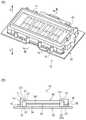
图2的(A)是表示本发明的实施方式的液晶显示装置的整体结构的立体图,图2的(B)是图2的(A)中B-B位置的剖视图。FIG. 2(A) is a perspective view showing the overall configuration of the liquid crystal display device according to the embodiment of the present invention, and FIG. 2(B) is a cross-sectional view at the position BB in FIG. 2(A).
图3是本发明的实施方式的液晶显示装置的分解立体图。3 is an exploded perspective view of the liquid crystal display device according to the embodiment of the present invention.
图4是电路板的立体图。4 is a perspective view of a circuit board.
图5的(A)是导光板的立体图,图5的(B)是在图5的(A)中从B方向观察的放大俯视图。FIG. 5(A) is a perspective view of the light guide plate, and FIG. 5(B) is an enlarged plan view viewed from the B direction in FIG. 5(A) .
图6是液晶面板的立体图。6 is a perspective view of a liquid crystal panel.
附图标记说明Description of reference numerals
1、玩具;10、液晶显示装置;11、盖构件;20、电路板;30、导光板;31、一个长边(第1缘部);32、另一长边(第2缘部);33、光入射部;332、圆周面(端面,相反的一侧的端面);34、光发出部;341、照射面;35、LED;371、第1缺口部(缺口部);372、第2缺口部(缺口部);40、液晶面板;42、显示面;51、第1连接器;52、第2连接器;53、第3连接器。1. Toy; 10. Liquid crystal display device; 11. Cover member; 20. Circuit board; 30. Light guide plate; 31. One long side (first edge); 32. The other long side (second edge); 33. Light incident part; 332. Circumferential surface (end surface, the end surface on the opposite side); 34. Light emitting part; 341. Irradiation surface; 35. LED; 2. Notched portion (notched portion); 40, liquid crystal panel; 42, display surface; 51, first connector; 52, second connector; 53, third connector.
具体实施方式Detailed ways
[本发明的实施方式][Embodiment of the present invention]
图1是表示使用了本发明的实施方式的液晶显示装置的玩具的整体结构的立体图。FIG. 1 is a perspective view showing the overall configuration of a toy using a liquid crystal display device according to an embodiment of the present invention.
图1所示的玩具1例如为游戏者佩戴于腰部使用的玩具,具有玩具主体2和安装于玩具主体2且用于供游戏者佩戴的带3。玩具主体2的中央部整体呈大致长圆形状,在其表面开口有大致长方形状的窗2a。而且,在玩具主体2的内部设有经由窗2a暴露在外部的液晶显示装置10。The toy 1 shown in FIG. 1 is, for example, a toy worn by a player around the waist, and has a
在玩具主体2的表面设有使用玩具1进行游戏时用于使液晶显示装置10工作的操作按钮4。而且,在玩具主体2的内部收纳有使液晶显示装置10工作的电池(省略图示)、利用操作按钮4的操作来控制液晶显示装置10的显示的控制部(省略图示)等。An
图2的(A)是表示本发明的实施方式的液晶显示装置10的整体结构的立体图,图3是本发明的实施方式的液晶显示装置10的分解立体图。另外,在以下的说明中,将图2的(A)和图3中的上方表示为“上”,将下方表示为“下”。如图2的(A)和图3所示,液晶显示装置10具有电路板20、设于电路板20的上方的导光板30、设于导光板30的上方的液晶面板40、将电路板20和液晶面板40电连接的连接器构件(第1连接器51~第3连接器53)、相对于导光板30照射光的发光构件(LED35)以及盖构件11。2(A) is a perspective view showing the overall configuration of the liquid
盖构件11覆盖导光板30、连接器构件(第1连接器51~第3连接器53)以及发光构件(LED35),能够固定于电路板20。而且,盖构件11具有长方形状的上开口12和比上开口12大的长方形状的下开口13。而且,在由盖构件11的四边构成的立壁14具有沿着外周面且用于安装于电路板20的多个安装部15,利用安装螺钉(省略图示)安装于电路板20。而且,液晶面板40的显示面42自上开口12暴露。The
图4是电路板20的立体图。如图3和图4所示,电路板20整体呈大致长方形状,设有用于将来自电池的电力向导光板30的LED35和液晶面板40供给的电路(省略图示)。而且,电路板20在俯视下呈大于盖构件11的外形,且与盖构件11的安装部15相对应地设有用于安装于盖构件11的缺口21、贯通孔22。FIG. 4 is a perspective view of the
图5的(A)是导光板30的立体图,图5的(B)是在图5的(A)中从B方向观察的放大俯视图。如图3和图5的(A)所示,导光板30作为液晶显示装置10中的背光灯发挥功能。导光板30在盖构件11的立壁14的内侧安装于电路板20的上侧。FIG. 5(A) is a perspective view of the
导光板30例如能够使用聚碳酸酯、丙烯酸等的树脂、玻璃等,但并不限定于此,只要透过光就能够进行应用,而且,在本实施方式中,导光板30形成为均匀的厚度。另外,对于导光板30,通过进行半透明或着色,能够作为背光灯对使液晶面板40如何发光进行调整。此外,对于导光板30,还能够使表面的一部分或全部进行镜面加工、压褶加工、发纹加工(日文:ヘアライン加工)等。而且,还可以使导光板30的厚度不均匀,局部较薄、较厚。For example, resins such as polycarbonate and acrylic, glass, etc. can be used for the
在导光板30的一个长边(第1缘部)31中,第1缺口部(缺口部)371形成为大致一条直线状,并设有多个(在此,两个)向外侧突出的突起373。而且,在另一长边(第2缘部)32侧形成有自长度方向中央部沿着电路板20的平面方向朝向外侧呈山形突出的光入射部33。在另一长边32侧,在隔着光入射部33的两侧设有第2缺口部(缺口部)372。而且,在光入射部33的顶部部分的端部设有在圆弧上凹陷而成的凹部331。而且,导光板30的一个长边31与另一长边32之间的整体呈大致长方形状的区域为朝向液晶面板40发出光的光发出部34,光发出部34的靠液晶面板40侧的面成为发出光的照射面341。另外,光入射部33和光发出部34利用一体成型连续形成。In one long side (first edge portion) 31 of the
如图5的(B)所示,凹部331具有圆周面(端面,相反的一侧的端面)332,与圆周面332相对地设有LED35。LED35安装于LED基板36。LED基板36与电路板20连接,并控制LED35。因而,在自电路板20经由LED基板36向LED35供给电力时,LED35朝向圆周面332照射光。照射到圆周面332的光自光入射部33被导入到光发出部34,自光发出部34的照射面341向液晶面板40照射光。As shown in FIG. 5(B) , the
如图3所示,在导光板30的一个长边31设有第1连接器51,在另一长边32设有第2连接器52和第3连接器53。第1连接器51具有横跨一个长边31的大致全长的长度。第2连接器52相对于光入射部33设于导光板30的长度方向上的一侧,第3连接器53相对于光入射部33设于与第2连接器52相反的一侧。由此,第1连接器51、第2连接器52以及第3连接器53能够在俯视时上下三个点稳定地保持液晶面板40。另外,在本实施方式中,第1连接器51、第2连接器52以及第3连接器53由条纹胶(日文:ゼブラゴム)形成,无力状态(日文:無力状態)下的上下方向上的高度设定为大于导光板30的厚度(参照图2的(B))。As shown in FIG. 3 , the
图6是液晶面板40的立体图。如图3和图6所示,液晶面板40具有长方形状的框部41,在框部41的内侧设有显示面42,该显示面42具有例如能够显示四位的数字的区段。在框部41的下表面设有电路(省略图示),电路连接于显示面42。而且,在框部41的下表面抵接有第1连接器51、第2连接器52以及第3连接器53,显示面42经由第1连接器51、第2连接器52以及第3连接器53与电路板20电连接。FIG. 6 is a perspective view of the
接着,参照图3和图2的(B)对液晶显示装置10的组装方法进行说明。首先,在电路板20的上侧的规定位置载置导光板30。然后,以与导光板30的光入射部33的凹部331相对应的方式,将安装了LED35的LED基板36安装于电路板20。Next, a method of assembling the liquid
然后,在设于导光板30的一个长边31的第1缺口部371安装第1连接器51,并且在设于另一长边32的第2缺口部372安装第2连接器52和第3连接器53。第1连接器51被设于第1缺口部371的突起373按压而定位。在此,第1缺口部371、第2缺口部372作为将第1连接器51、第2连接器52以及第3连接器53支承于导光板30的支承部发挥功能。而且,第1缺口部371的形状、第2缺口部372的形状分别成为与第1连接器51的形状、第2连接器52的形状以及第3连接器53的形状相对应的形状。通过在第1缺口部371、第2缺口部372嵌合第1连接器51、第2连接器52以及第3连接器53,能够容易地进行第1连接器51、第2连接器52、第3连接器53的定位。Then, the
接着,在导光板30的上侧载置液晶面板40。此时,第1连接器51的高度、第2连接器52的高度以及第3连接器53的高度大于导光板30的厚度,因此,液晶面板40被第1连接器51、第2连接器52以及第3连接器53支承。最后,自液晶面板40的上侧覆盖盖构件11,于是,盖构件11的上开口12的缘部121与液晶面板40的框部41的上表面抵接,盖构件11的下端部悬浮并停止在电路板20的上表面的上方。Next, the
该状态下,将安装螺钉(省略图示)自上方插入于盖构件11的安装部15并拧入于电路板20,于是,液晶面板40的框部41的下表面被安装为对由条纹胶形成的第1连接器51、第2连接器52以及第3连接器53进行压缩。因此,收纳于盖构件11的内部的导光板30以及液晶面板40在条纹胶的弹性力的作用下被可靠地保持于规定位置,并且,液晶面板40可靠地与电路板20电连接。另外,液晶显示装置10借助盖构件11安装于玩具主体2的内部。或者,还能够借助电路板20安装于玩具主体2。In this state, a mounting screw (not shown) is inserted into the mounting
在本实施方式所涉及的液晶显示装置10中,第1连接器51设于导光板30的一个长边31,第2连接器52和第3连接器53空开规定间隔地设于导光板30的与一个长边31相对的(相反的一侧的)另一长边32。因此,能够在三个点保持液晶面板40,因而能够稳定地保持液晶面板40。而且,通过在第2连接器52和第3连接器53之间设置LED35并向导光板30照射光,能够利用一个LED35向液晶面板40照射充分的光量,能够使结构简单化。In the liquid
而且,在本实施方式所涉及的液晶显示装置10中,导光板30具有包含朝向液晶面板40照射光的照射面341的光发出部34和与光发出部34连接并沿着电路板20的平面方向朝向自光发出部34远离的方向突出的光入射部33。光入射部33呈山形形状,在与光发出部34相反的一侧的顶部设有具有圆周面332的凹部331。而且,以朝向圆周面332照射光的方式配置有LED35。因此,能够利用一个LED35向液晶面板40照射充分的光量,能够使结构简单化。而且,能够经由圆周面332使向导光板30入射的光均匀。Furthermore, in the liquid
而且,在本实施方式所涉及的液晶显示装置10中,导光板30设有对第1连接器51、第2连接器52以及第3连接器53进行支承的支承部。因此,能够容易地进行第1连接器51、第2连接器52以及第3连接器53的相对于导光板30的定位。Furthermore, in the liquid
而且,在本实施方式所涉及的液晶显示装置10中,由于包括盖构件11,因而能够在规定的位置固定导光板30、液晶面板40、第1连接器51、第2连接器52、第3连接器53以及LED35。Furthermore, in the liquid
而且,本实施方式所涉及的液晶显示装置10能够应用于各种玩具。在本实施方式中,示出了应用于玩具1的例子,通过将液晶显示装置10收纳于玩具主体2,例如在玩具主体2安装带3,游戏者能够将玩具1安装于腰部而使用液晶显示装置10进行游戏。Furthermore, the liquid
本发明的液晶显示装置10和使用了该液晶显示装置10的玩具1并不限定于上述的实施方式,能够进行适当的变形、改良等。例如,在上述的实施方式中,对在收纳了液晶显示装置10的玩具主体2安装带3而构成玩具1的情况进行了说明,但还能够构成为使用了液晶显示装置10的移动电话那样进行游戏。The liquid
Claims (6)
Applications Claiming Priority (2)
| Application Number | Priority Date | Filing Date | Title |
|---|---|---|---|
| JP2018146502AJP6621881B1 (en) | 2018-08-03 | 2018-08-03 | Liquid crystal display device and toy using the same |
| JP2018-146502 | 2018-08-03 |
Publications (2)
| Publication Number | Publication Date |
|---|---|
| CN110426896A CN110426896A (en) | 2019-11-08 |
| CN110426896Btrue CN110426896B (en) | 2022-05-24 |
Family
ID=68411386
Family Applications (1)
| Application Number | Title | Priority Date | Filing Date |
|---|---|---|---|
| CN201910695563.XAActiveCN110426896B (en) | 2018-08-03 | 2019-07-30 | Liquid crystal display device and toy using the same |
Country Status (2)
| Country | Link |
|---|---|
| JP (1) | JP6621881B1 (en) |
| CN (1) | CN110426896B (en) |
Families Citing this family (1)
| Publication number | Priority date | Publication date | Assignee | Title |
|---|---|---|---|---|
| EP4379479A3 (en) | 2020-03-18 | 2024-10-16 | Casio Computer Co., Ltd. | Display device and timepiece |
Citations (9)
| Publication number | Priority date | Publication date | Assignee | Title |
|---|---|---|---|---|
| CN1716024A (en)* | 2002-08-30 | 2006-01-04 | 富士通显示技术株式会社 | Liquid crystal display device and manufacturing method thereof |
| CN101210976A (en)* | 2006-12-25 | 2008-07-02 | 鸿富锦精密工业(深圳)有限公司 | Light guide plate and backlight module |
| CN101793366A (en)* | 2009-02-02 | 2010-08-04 | 索尼公司 | Surface light source device and display device |
| CN101910917A (en)* | 2008-03-25 | 2010-12-08 | 夏普株式会社 | Liquid crystal display device |
| CN102155684A (en)* | 2010-01-29 | 2011-08-17 | 三星电子株式会社 | Backlight assembly and display device having the same |
| CN102262262A (en)* | 2011-07-01 | 2011-11-30 | 青岛海信电器股份有限公司 | Light guide plate, backlight module and display device |
| WO2014034477A1 (en)* | 2012-08-27 | 2014-03-06 | ヤマハモーターエレクトロニクス株式会社 | Liquid crystal display device |
| CN105597346A (en)* | 2014-12-02 | 2016-05-25 | 万代股份有限公司 | Performance output toy |
| CN108267889A (en)* | 2016-12-30 | 2018-07-10 | 乐金显示有限公司 | Liquid crystal display |
Family Cites Families (10)
| Publication number | Priority date | Publication date | Assignee | Title |
|---|---|---|---|---|
| JPS59109384U (en)* | 1983-01-13 | 1984-07-23 | 株式会社ケンウッド | LCD display board mounting structure |
| JP3107706U (en)* | 2004-09-13 | 2005-02-03 | 有限会社ハル・コーポレーション | Display toy |
| JP4685074B2 (en)* | 2007-10-16 | 2011-05-18 | シャープ株式会社 | Reflective liquid crystal display |
| JP2010054718A (en)* | 2008-08-27 | 2010-03-11 | Sony Corp | Display device |
| KR101858255B1 (en)* | 2011-10-19 | 2018-05-16 | 엘지디스플레이 주식회사 | Guide member for Light Guide Panel and Liquid Crystal Display using the same |
| TWI435023B (en)* | 2012-01-04 | 2014-04-21 | Coretronic Corp | Light source module |
| JP2016051515A (en)* | 2014-08-28 | 2016-04-11 | 株式会社ジャパンディスプレイ | Luminaire and display device |
| JP6653900B2 (en)* | 2015-03-03 | 2020-02-26 | 久豊技研株式会社 | Surface emitting device and image forming apparatus |
| JP6478050B2 (en)* | 2015-05-15 | 2019-03-06 | パナソニックIpマネジメント株式会社 | Surface light source lighting device |
| CN107577008A (en)* | 2017-09-01 | 2018-01-12 | 昆山龙腾光电有限公司 | The preparation method of display device and display device |
- 2018
- 2018-08-03JPJP2018146502Apatent/JP6621881B1/enactiveActive
- 2019
- 2019-07-30CNCN201910695563.XApatent/CN110426896B/enactiveActive
Patent Citations (9)
| Publication number | Priority date | Publication date | Assignee | Title |
|---|---|---|---|---|
| CN1716024A (en)* | 2002-08-30 | 2006-01-04 | 富士通显示技术株式会社 | Liquid crystal display device and manufacturing method thereof |
| CN101210976A (en)* | 2006-12-25 | 2008-07-02 | 鸿富锦精密工业(深圳)有限公司 | Light guide plate and backlight module |
| CN101910917A (en)* | 2008-03-25 | 2010-12-08 | 夏普株式会社 | Liquid crystal display device |
| CN101793366A (en)* | 2009-02-02 | 2010-08-04 | 索尼公司 | Surface light source device and display device |
| CN102155684A (en)* | 2010-01-29 | 2011-08-17 | 三星电子株式会社 | Backlight assembly and display device having the same |
| CN102262262A (en)* | 2011-07-01 | 2011-11-30 | 青岛海信电器股份有限公司 | Light guide plate, backlight module and display device |
| WO2014034477A1 (en)* | 2012-08-27 | 2014-03-06 | ヤマハモーターエレクトロニクス株式会社 | Liquid crystal display device |
| CN105597346A (en)* | 2014-12-02 | 2016-05-25 | 万代股份有限公司 | Performance output toy |
| CN108267889A (en)* | 2016-12-30 | 2018-07-10 | 乐金显示有限公司 | Liquid crystal display |
Also Published As
| Publication number | Publication date |
|---|---|
| CN110426896A (en) | 2019-11-08 |
| JP2020021011A (en) | 2020-02-06 |
| JP6621881B1 (en) | 2019-12-18 |
Similar Documents
| Publication | Publication Date | Title |
|---|---|---|
| US8605232B2 (en) | Display backlight having light guide plate with light source holes and dual source packages | |
| JP2012028323A (en) | Light guide assembly | |
| JP4349557B2 (en) | Liquid crystal display | |
| CN101755317A (en) | Structure for illuminating key operation section, electronic device, mobile device and method for illuminating key operation section | |
| JP2011248863A (en) | Touch type transparent keypad | |
| CN110426896B (en) | Liquid crystal display device and toy using the same | |
| JP7469027B2 (en) | Liquid crystal display device and toy using the same | |
| HK40010263B (en) | Liquid crystal display and toy using the liquid crystal display | |
| HK40010263A (en) | Liquid crystal display and toy using the liquid crystal display | |
| US11874490B2 (en) | Display apparatus | |
| TW201413336A (en) | Liquid crystal display device | |
| JP5401641B2 (en) | Floor-buried guide light device | |
| US20190033680A1 (en) | Wearable device | |
| US20190033794A1 (en) | Wearable device | |
| JP2003036715A (en) | Surface light source device and liquid crystal display device | |
| JP7133782B2 (en) | Display device | |
| CN220506582U (en) | Light emitting structure and beauty equipment | |
| CN222788326U (en) | Beauty Instrument | |
| CN218920731U (en) | Electronic device | |
| JP5287045B2 (en) | Liquid crystal display | |
| CN222397053U (en) | Electronic atomizing device | |
| WO2019200992A1 (en) | Light guide structure, casing, and electronic device | |
| CN115445096B (en) | Physiotherapy device | |
| TWM469798U (en) | Luminous mirror structure | |
| CN203630954U (en) | Electronic machine |
Legal Events
| Date | Code | Title | Description |
|---|---|---|---|
| PB01 | Publication | ||
| PB01 | Publication | ||
| SE01 | Entry into force of request for substantive examination | ||
| SE01 | Entry into force of request for substantive examination | ||
| REG | Reference to a national code | Ref country code:HK Ref legal event code:DE Ref document number:40010263 Country of ref document:HK | |
| GR01 | Patent grant | ||
| GR01 | Patent grant |