CN1103901C - Electronic thermostat having high and low voltage control capability - Google Patents
Electronic thermostat having high and low voltage control capabilityDownload PDFInfo
- Publication number
- CN1103901C CN1103901CCN95104732ACN95104732ACN1103901CCN 1103901 CCN1103901 CCN 1103901CCN 95104732 ACN95104732 ACN 95104732ACN 95104732 ACN95104732 ACN 95104732ACN 1103901 CCN1103901 CCN 1103901C
- Authority
- CN
- China
- Prior art keywords
- thermostat
- connector
- terminal
- joint
- fastening
- Prior art date
- Legal status (The legal status is an assumption and is not a legal conclusion. Google has not performed a legal analysis and makes no representation as to the accuracy of the status listed.)
- Expired - Lifetime
Links
Images


Classifications
- G—PHYSICS
- G05—CONTROLLING; REGULATING
- G05D—SYSTEMS FOR CONTROLLING OR REGULATING NON-ELECTRIC VARIABLES
- G05D23/00—Control of temperature
- G05D23/19—Control of temperature characterised by the use of electric means
- G05D23/1902—Control of temperature characterised by the use of electric means characterised by the use of a variable reference value
Landscapes
- Physics & Mathematics (AREA)
- General Physics & Mathematics (AREA)
- Engineering & Computer Science (AREA)
- Automation & Control Theory (AREA)
- Control Of Temperature (AREA)
- Air Conditioning Control Device (AREA)
Abstract
Description
The invention relates to electronic thermostat, more specifically say so about being suitable for controlling the thermostat of fan coil unit (fan coil units) and similar heating and cooling device.
Usually being used to of seeing in many government buildings, school and hotel controlled single room, access road, hall passage etc. and locates the heating and cooling equipment of temperature and often be known as the fan coil unit.This unit uses heating and/or cooling coil to combine with fan to control the temperature in their spaces, place usually.The system at fan coil place can be so-called two-pipe system (two pipesystem), and fan coil is wherein used single feed pipe and single return pipe, makes according to its operator scheme and flows through hot water or cold water in the feed pipe, thereby realize heating or cooling.Should be appreciated that, in two-pipe system, can not provide hot water and cold water simultaneously.
The fan coil unit also can connect into four guard systems, wherein uses water supply and return pipe to go cooling, and water supply and return pipe go heating.The fan coil unit usually utilizes the electric heating unit as this fan coil unit part to make it to have the ability that supplemental heat is provided.This fan coil unit has the flow of valve control by water supply and return piping usually, controls the fan of the overhead throughput of coil pipe in addition, also provides air door (damper) with the ratio of control by the enter air and the air of going out of this unit usually.There are multiple formation and design in the fan coil unit, comprises for example different fan operation voltage and auxiliary electro-heat unit operations voltage.Usually the fan coil unit has 24 volts, 120 volts, 208-230 lies prostrate and 277 volts operating voltage.Control to the fan coil unit also can change, show that the extraneous air that control will be heated or cooled also can be changed with the air door that the better quality room air is provided, can reformedly also have by-pass valve control thereby control from the heating of feed pipe and/or the ability of cooling liquid flow.Have, the speed of controlling the fan that passes coil pipe (it represents the heat exchanger of this unit) air capacity also can be controlled again.
No matter how are the design of fan coil unit and structure, also no matter they mainly so that how mode is controlled, a thermostat is necessary to the operation of controlling this unit.Because various possible operating characteristics are arranged, so still there is not a kind of single thermostat design can be used for operating major part in whole commercial getable different fan coil unit up to now.Have, because different operating voltages can be arranged, " Underwriter complys with specification in the laboratory " drawn such result: make isolation of components such as thermostat and control relay again.And this point has increased expense to the user, because switch, relay and the relevant controller that separates with thermostat must be installed.
Therefore, a main purpose of the present invention provides a kind of improved thermostat, has fan coil unit much different and variable operation and design characteristics in order to control.
Another object of the present invention provides a kind of improved thermostat, it can be contained on the fan coil unit or adorn on the wall, and it can provide the control to high-pressure side equipment (as air door, switch, valve and so on) and low-pressure end equipment, and this control has the high-pressure section of separation by one and the single thermostat of low-pressure section is finished.Rely on unique design, this thermostat can be contained in 4 * 4 inches common square electric boxes, and only need in the middle of box, place a shim high-pressure section and low-pressure section are separated.
Another object of the present invention provides a kind of so improved thermostat, it can utilize places or removes some jumpers and easily dispose thermostat, thereby enables easily to be configured to operate in many fan coil unit with different operating voltage and operating characteristic any one.
One more specifically purpose provide a kind of so improved thermostat, if desired, it can easily be configured to fan speed control operation mode and be different from valve and air door control type.
Another purpose provides a kind of improved thermostat, and it also can be four guard systems that its operable fan coil device both can be assembled into two-pipe system.
Another object of the present invention provides a kind of like this thermostat, it has a microprocessor to be used to the input signal that is provided by temperature sensor is provided and produces control signal, and it provides suitable control function to be used for the system type that fan coil is configured to form automatically.
A further object of the invention provides a kind of improved thermostat, it has the ability to control auxiliary electro-heat device and its by-pass valve control and the air door of fan coil, this thermostat is applications exploiting remote temperature sensing device also, if this device is installed.This device is different from as sensing device on the plate of a thermostat part.
Another object of the present invention provides a kind of so improved thermostat, it has a cycle tests, can move according to hope in installation process, this cycle tests can determine whether the thermostat of being installed can normally bring into play its function between the actual operating period.
According to a kind of thermostat of the present invention, be used for control heating and chilling unit, this type of heating and chilling unit comprise a fan and at least one terminal installation, this terminal installation is made up of at least one heating and refrigeration fluid control valve, at least one electric heater unit and at least one air dampers, and described thermostat comprises:
One is suitable for being contained in the lip-deep bottom of installation;
A cover part that is suitable for being fixed on the described bottom;
Be used to control the switching device of this thermoregulator work, described switching device and described cover part link and can be approaching so that operation;
Temperature setting device and described outer cover link, and are used to set the nominal temperature set point;
With the treating apparatus that described bottom links to each other with one of cover part, be used to receive mode of operation signal and temperature indication signal and produce output signal selectively with control heating and chilling unit;
First temperature sensing device is used for the air themperature in perception space that this thermostat is controlled;
One group of first jockey is used to connect the high voltage circuit of selected terminal installation association;
One group of second jockey is used to connect the low voltage circuit of selected terminal installation association.
According to an electric connection of the present invention, be used for connection and be positioned at the lip-deep relatively leading foot in a bottom two, this bottom has one first side and one second side and at least one joint opening to open at least one first madial wall, and the composition of described joint is:
A flexible joint partly has the first and second flexible contact arms adjacent one another are, is applicable to that accepting electric parts from described first side draws binding post;
A terminal protuberance blank area is electrically connected on described flexible joint part and passes the extension of one of described joint opening, and it is applicable to the electric conductor from described second side provides a tie point; And
Be fixed on the fastener on the described blank area, be used for described joint removably is fixed on base unit, thereby described protuberance blank area is forced on the described sidewall.
According to one of the present invention electric connection that is used to connect the connection pin that is positioned at the relative both sides of base unit with bottom fastening surface, described electric connection comprises:
A joint component that is generally serpentine, having a blank area to have the first and second flexible contact components extends along the direction of insertion at the one end, one terminal protuberance blank area is arranged an opposite end, and a neck combines described blank area with described terminal protuberance blank area; And
Be fixed on the fastener on the described blank area, be used for described protuberance joint removably is fixed on the described bottom fastening surface of described base unit.
According to a joint terminal arrays of the present invention, the electric conductor of using this an array has a base unit, this base unit has first surface and second surface and first side and second side, one of at least the first and second sides have a lead channels to have one group of socket, one group of opening and one group of fastening structure, and described array comprises:
At least one flexible joint partly has the first and second flexible contact elements to extend along a direction of insertion that is positioned at the plug wire post of first side, adjacent bottom unit, and an end of described blank area is made into can insert one of described socket;
At least one terminal ledge is electrically connected on described flexible joint part and extends along the rightabout of described direction of insertion, to be connected to the leading foot that is positioned at base unit second side, each described terminal protuberance blank area comprises a terminal protuberance, and it is made into and can stretches out away from described base unit by one of described opening; And
At least one fastener is connected described blank area, removably to be fastened on the base unit described each several part, described secure component comprises a tubulose secure component, is made into and described fastening structure engagement, is used for applying adjustable fastening force to it.
After reading following description with reference to the accompanying drawings, it will be apparent that other purposes and advantage.These accompanying drawings are:
Fig. 1 is a perspective view of implementing thermoregulator of the present invention, among the figure outer cover and bottom branch has been separated from each other;
Fig. 2 is the bottom view of bottom shown in Figure 1;
Fig. 3 is the exploded perspective illustration that is contained in the thermostat in 4 * 4 inches common electric square boxes;
Fig. 4 is the printed circuit board diagram of observing from the inside of cover part;
Fig. 5 is the parts decomposition view of adapter assembly of the present invention;
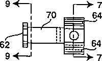
Fig. 6 is the end-view of the part of adapter assembly shown in Figure 5;
Fig. 7 is generally along 7-7 sectional view that line is done among Fig. 6;
Fig. 8 is the end-view of adapter assembly shown in Figure 5;
Fig. 9 is generally along 9-9 sectional view that line is done among Fig. 6;
Figure 10 is the secure component of adapter assembly of the present invention and the plane of bolt;
Figure 11 is the installation circuit diagram of this thermostat in the application of low pressure fan coil pipe unit; And
Figure 12 a and 12b constitute the circuit diagram of thermostat of the present invention together.
Put it briefly, the thermostat that the present invention constitutes is specially adapted to control various heating and chiller, and is specially adapted to control fan coil heating and chiller, those that use in building government building, school, hotel.Although this thermostat is specially adapted to control the fan coil unit, but it is not limited to control the specific unit of this class certainly, but can be used to control any multiple heating and chiller, for them, thermostatic control is useful and wishes the mechanical terminal installation of control, the device that links to each other with a thermostat or controller as valve operation device, fan and air door etc.Thermostat of the present invention is flexible especially aspect its operating function, and it is designed to control its operating voltage at a terminal installation that changes in quite on a large scale.
In this respect, thermostat of the present invention has been adapted to 24 volts of alternating currents (VAC) control, also can directly control the device of 120VAC and 208-230 and 277VAC.This thermostat can be arranged for any of these operating voltages, and have that relay can switch the terminal installation with one of aforesaid operations voltage on the plate, and can control current loading up to several amperes, even when operating voltage also be like this during at 277VAC.This device is consistent with the UL873 specification, can install to the fan coil unit originally on one's body, also can install on the wall.This thermostat can provide automatic or manual control under heating or refrigeration mode of operation.This thermostat also can be worked under the on/off control mode, also can be used as fan speed on/off controller or temperature controller, they or work at automated manner or under mode of heating or refrigeration mode, and under on/off temperature controller mode, work.This thermostat has an index dial knob to be used to set the desired temperature in controlled space.Terminal installation can move under 24VAC, also can move under aforementioned high voltage.
When this thermostat will be used to control the 277VAC terminal installation; It can directly be controlled and valve and the fan motor of operation element in 277VAC.When this thermostat was installed on the wall of distant place, it can not directly control the 277VAC terminal installation, and in this configuration, thermostat provides 24 volts of output signals to be arranged in the relay of fan coil unit with control.If this thermostat is designed to supply voltage is not that thereby thermostat will enter off-position automatically and unpredictable operation can not take place when specifying voltage, and promptly thermostat is de-energized protection.
Get back to accompanying drawing, particularly Fig. 1 now, implement thermostat of the present invention for one and represent withlabel 20 that usually Fig. 1 is an exploded perspective illustration.Thermostat has a bottom (representing with 22 usually) and a cover part (representing with 24 usually), has the rotatable index dial knob 26 of a temperature set points and is used to be provided with nominal set-point temperature.Knob 26 is suitable for being connected cover part 24.Index dial knob 26 has turning handle 28, and it has an open end (split end) 30 (Fig. 4) to be suitable for mechanical connection to be contained inpotentiometer 32 on the printed circuit board (PCB) 34, and printed circuit board (PCB) is contained in the inside of cover part 24.With nipper plier open end is clipped together just and can take away index dial knob 26.Cover part has a semicircle opening 36, wherein can insert a protuberance (not drawing among the figure), it has limited one section predetermined circular arc of index dial knob, and this figure arc is printed on the temperature indication numbers in the above corresponding to the high and low temperature setting of thermostat.
When removing the index dial knob, the opening 38 of an amplification manifests the jumper of an exposure, and it can be by short circuit so that start a cycle tests, to determine whether operate as normal of this thermostat.In case should test jumper by short circuit, then cycle tests clockwise rotates fully to put in place to start from the set-point potentiometer and is not with the test that changes temperature test.It fully counter-clockwise direction rotate in place to start the test that band changes temperature test.This starting point is determined indoor or whether air themperature is higher than 60 °F and be lower than 80 °F.
Initial:
-05 timer=0
If-10 set-points are in maximum then forward 40 to
If-20 set-points are not in minimum of a value then change " failure "
If-30 turn to temperature>60 and<80 then change 40, otherwise change " failure "
If-40 is indoor or return air themperature>60 and<80 then change and go 50, otherwise change " failure "
If-50 normally closeds inputs=" short circuit " then change and go 60, otherwise change " failure "
If-60 timers=5 second then replenishoutput 1,output 2, air door, second heating period
-65 establish timer=0
-70 commentaries on classics go 10
" failure ":
-80 are provided withoutput 1,output 2, and air door, second heating period=relay is energized
-90 forward 5 to
-100 finish
Stop test,, thereby and index dial knob turning handle 28 pushed back its installation site recovery set-point index dial as long as remove jumper.
Thermostat also has a microprocessor 40 and a pair of slide switch 42 and 44, and they control fan and thermostat working method respectively.Microprocessor 40 (seeing Figure 11 b) is Motorola HC05 microprocessor preferably, and it realizes function as described herein after revising.
About speed controller for fan 42 (as shown in Figure 1, also with reference to figure 12a), it is one four position switch preferably, from left to right have " breaking ", " height ", " in ", " low " four positions, this makes fan earlier switch to " height " speed from " breaking " in being placed in or before the low speed.About switch 44, its leftward position is " breaking ", and other positions are " automatically ", " heating " and " refrigeration " working method.These switches can slide in notch 46, and these notches form in rectangle insert 48, and insert 48 preferably is securely fixed on thecover part 24; This insert 48 can have elongated degree notch 46 to be used to limit the sliding stroke of switch, if the configuration of specific thermostat defines the function of this thermostat.For example, about fan speed switch 42, some wish that fan is switched off never in using, and in this case, just can eliminate " breaking " state effectively by moving to " breaking " position left with short notch 46 pinning switches 42.Cover part 24 also has a plurality of openings 50 around thermostat, making provides air circulation to thermostat inside, and portion is placed with the temperature-sensitive thermistor within it.
According to an important aspect of the present invention, bottom 22 is easy to separate withcover part 24, and the bottom is suitable for being connected with the electric conductor that extends to controlled fan coil unit.Cover part and bottom all are with plastic, Cylolac ABS plastic preferably, and it has UL 94-5VA inflammability UL rated value.Two blank areas 52 and 54 are arranged atbottom 22, and each has 7 contacts to be used for outer lines is linked thermostat.
Each blank area 52 and 54 has 7single adapter assemblies 56, and their building block is shown in Fig. 5-9.There is anopening 58 to be used to make each adapter assembly to extend to pass completely through the bottom bottom 22.Opening 58 is suitable for making conductor on 22 outer surfaces of end fitting 60 usefulness bottoms or lead to be connected on the electric conductor or binding post on 22 inner surfaces of bottom.End fitting 60 has aterminal protuberance 62, and it extends by opening 58 and has anaperture 63 to meet the requirement of industrial standard spade protuberance near its outer end.Another kind of mode is,adapter assembly 56 is suitable for being connected to like this on a conductor and the lead: with end fitting 60 fall back on opening 58 than the left side one side, thereby conductor or lead can be inserted between perforated wall and theprotuberance 62,protuberance 62 is moved so that its clamped conductor that fixes the centre to sidewall.
Each end fitting 60 also has a pair of fixed arm 64, and they are applicable to the binding post joint of accepting to be contained on the printed circuit board (PCB) 34 66, and printed circuit board (PCB) 34 is fixed on the cover part 24.End fitting 60 also has a connecting portion 68 and neck 70.Although end fitting 60 contiguous fasteners 72 shown in Figure 5, in the adapter assembly that combines, square and have the secure component 72 (shown in Figure 10) of middle opening 73 to be suitable for making terminal protuberance 62 to pass it, thereby when secure component is moved to the left, terminal protuberance 62 closely is pressed on the sidewall of contiguous surface or chassis split shed 58, as shown in Figure 2.Fastener 72 is fastening by screw 74, and this screw is applicable to and abuts against one of respective annular surface (see figure 1) that constitutes in blank area 52 and 54.Terminal protuberance 62 has the mechanical damping means, and as the sawtooth 78 that forms on the protuberance 62, its engagement lead also maintains lead, thereby lead is not easy to be drawn out next when thermoregulator is mounted.In this respect, this is that high voltage lead considered here connects that to bear the pulling force that UL486E requires necessary.For the lead of 14AWG, it connects must be with 11.5 pounds pulling force, and the sawtooth on terminal protuberance 62 makes adapter assembly can pass through this test.
Each blank area 52 and 54 has a joint outer cover 80 to sting on bottom 22 and by bottom 22 to hold on, this is covered with many openings 82 and is used to acceptbinding post 66, also has many lateral openings 84 to be used to acceptbolt 74 outer lead is linked the thermoregulator joint.An openr mid portion 86 is arranged at the bottom, for the element that installation volume is bigger on the printed circuit board (PCB) that is positioned atcover part 24 inside provides the space.
More particularly, with reference to figure 4, thermostat can comprise relay 88 and 90 and transformer 92.Space 86 is also with blank area 52 with opened in 54 minutes, and according to an important aspect of the present invention, one of blank area 52 links to each other with low-voltage circuit, and blank area 54 links to each other with the high voltage circuit joint.The special meaning of this point is that this thermostat is suitable for being contained in 4 * 4 inches common square boxes (shown in Figure 3) and installs to be used for wall.If it is the terminal installation of one of 110VAC, 208-230VAC or 277VAC that thermostat 20 is used for controlling those operating voltages of fan coil unit, just so as long as shown in the shim 95 of packing in 4 inches square boxes can make thermostat be applicable to these devices of control.Utilize this shim just can defer to Underwriter laboratory (UL) specification.Installation may be wished additional common stickup ring 96 on thermoregulator, can be fixed on common screw on the stickup ring 96 and scabble plate 98.Can provide decoration wallboard and preferred design to become can receive bottom 22, it fixes with two bolts 102, and cover part 24 can be fixed on the bottom.Although it is with a friction engagement system and confining force is provided that keeping arm 64 is accepted binding post 66, cover part 24 also has many fit (not drawing among the figure) on the surface within it, projection 104 is wherein arranged, thus when cover part be forced into the bottom above the time cover part 24 just bite bottom 22.
As previously mentioned, implement thermostat of the present invention and be applicable to low voltage devices and 120 volts of other three above-mentioned operating voltages, 208-230 volt and 277 volts.This thermostat also is applicable to fan coil two-tube or four pipe units.Two-tube low pressure is installed and is shown in Figure 11, and this figure represents the type of used terminal device and circuit prevailingly and has nothing to do with voltage levvl.In the schematic diagram of Figure 11, shown inthermostat 20 be connected on theterminal strip 110 in the binding box in the fan coil unit, and the circuit of fan coil unit comprisesfan motor relay 116 power supplies, and relay 116 conforms to and is added to three control signals on the lead 118, in these signal enabling relays suitable one with provide high, in or low fan speed.Power supply on thelead 120, and fuse 122 is arranged at input.Electric contact 124 is used to control the use of electrical auxiliary heater (usually withlabel 126 indications), and the operation of these contacts is by line 128 controls.
Shown in the fan coil unit have anair door 130 andvalve 132 to be used to control fluid flow by fancoil.Air door 130 is by relay plug-inunit 134 control, and relay plug-inunit 134 is byline 136 controls fromthermoregulator 20, and valve is by also beingline 138 controls from thermoregulator 20.A shut-off circuit that is provided byline 140 can be provided thermostat, and it can be linked condensate and cross on flow sensor or the icing protection sensor.If one of these situations take place, may wish to turn offthermostat.Line 142 is linked (temperature) transformative transducer, and it is a temperature sensor, and it provides temperature about the supply pipe inner fluid of fan coil to thermostat.
Forward the operation of thermostat now to.When switch 44 is placed the appropriate location so that thermostat when being in automatic operation, switch 42 control fan and fan speed conversion.Switch 44 control heating and refrigerating functions, thereby " HEAT (heating) " position is corresponding to manual heating.When being in the manual heating mode, will refrigeration can not take place." COOL (refrigeration) " is provided with corresponding to manual refrigeration, will can not heat on this position." AUTO (automatically) " promptly is provided with representative with mapping mode heating and refrigeration automatically automatically by switch 44, controls this conversion by being installed in sensor at a distance in two-pipe system.In four guard systems, microprocessor 40 determines whether conversion heating or refrigeration automatically." OFF (breaking) " position of switch 44 is turned off fan coil and thermostat.All terminal installations such as valve, air door etc. all enter not power supply state on that position.Under the situation that two way valve is opened usually in fan coil, " breaking " is corresponding to valve is opened fully.When switch 44 is defined to just " lead to " and " breaking " switch, thermostat will be determined to heat or refrigeration automatically, so do not have manual heating or refrigerating function.Yet even switch 44 is in " breaking " state, fan may work on.
In two-pipe system, only use a valve, the auxiliary electrical heating can be used in two-tube control.Use two valves in four guard systems are installed, a valve is used for refrigeration control forward (direct) action, and second valve is used for heating and is reverse action.Thermostat microprocessor 40 will determine it will will be any mode of operation via the conversion input.If be connected into a sensor, then use two-tube control.If do not connect sensor, then microprocessor will be operated in four management and control system modes.In four pipes, do not use the electrical heating operation, but work at the second heater stages heater.Operation extraneous air valve function in four tube side formulas.
Transformative transducer should be any state to thermostat indication current operation status, makes the heating valve event when the heating operation state, but the refrigeration valve is failure to actuate.Conversely, make the akinesia of heating valve at refrigeration condition, but the refrigeration valve can be moved.Transformative transducer causes a conversion to refrigeration when temperature preferably surpasses 85 left and right sides, and the conversion to heating preferably takes place when temperature is lower than 55 left and right sides.When powering up, if the temperature of perception between about 55 °F and 85 °F the time predetermined state of conversion preferably heat.
Electrical heating is undertaken, i.e. the compole and the second level by two steps.The operating temperature of auxiliary heating operation deducts instrument dead zone (dead band) temperature (being approximately 3.6 ° or about 10 ° as required) by set-point dial plate temperature and determines.Second level heating operation when temperature is in set-point dial plate temperature and deducts instrument dead zone temperature and deduct extra about 1.8 again.
About temperature control, when dut temperature raises and surpass about 0.9 of set point temperatures, thermostat starting refrigeration sequence.Thermostat maintenance refrigeration condition is reduced to until dut temperature and is lower than about 0.9 of set point temperatures.Thermostat finishes refrigeration condition and enters instrument dead zone state then.The operation of heating function is similar to refrigerating function, but depends on the pipe-line system of fan coil.In two-pipe system, have only when transformative transducer to microprocessor indicate have hot water after thermostat just can enter heating function.In case perception the existence of hot water, then heating function resembles and operates the refrigerating function, just valve is by reverse motion action.When dut temperature is lower than when adding about 0.9 of temperature set-point (heating set-point be that the refrigeration set-point deducts instrument dead zone temperature), to valve energize (with the same valve of refrigeration, but with reverse action).Thermostat keeps heated condition, until dut temperature rise to heating be provided with on till about 0.9 °F.
In four manage-styles fan coil pipe controller, do not utilize transformative transducer.Thermostat uses dut temperature and set point to subtract the two official post second valve of dead zone temperature and can work to heat.Hot-air also must be lower than about 0.9 of hot spot temperature.Heating valve keeps being powered state and rises to heating setpoint until temperature and put till above about 0.9 °F.Dut temperature will be from thesensor 32 that is contained on the printed circuit board (PCB).Be connected into long-rangely when returning air borne sensor when the microprocessor 40 of thermostat detects, it will use distance sensor automatically and not consider to be contained insensor 32 on the PC plate.These two temperature preferably by microprocessor with per at least 5 seconds frequency samples once.
About the air door of extraneous air, it all works in all thermostat configurations.In all fan coil, may connect also and may not connect air door.The air door output is a two condition output.Air door is minimum to be preferably in machinery setting on the air door driver with maximum.Air door control has two kinds of modes of operation, and they are " IAQ " (inlet air quality) and " maintenance ".The IAQ mode forces microprocessor and always open air door in the fan work process.
Thermostat has circuit to realize above-mentioned functions, and this circuit is shown in Figure 12 a and Figure 12 b.Circuit arrangement is on printed circuit board (PCB) 34.Terminal 1 to 14 is shown in Fig. 2, and when coverpart 24 when mode is connected as described above with bottom 22, these terminals link to each other with binding post shown in Figure 4 respectively.They are also shown in left side among Figure 12 a asterminals P 1 and P14, and have indicated function separately on the terminal marking next door.
Terminal block is just like lower terminal and the function followed:
The pin denotational description connects wire type
The high or low voltage AC of 1~line power
The high or low voltage AC of 2 circuit common ports
The high or low voltage AC of 3 H fan high speeds
The high or low voltage AC of 4 M fan middling speeds
The high or low voltage AC of 5 L fan low speed
6 01 outputs, 1 high or low voltage AC
7 02 outputs, 2 high or low voltage AC
8 D air door output LOW voltage DC
9 S close the low electric DC of input usually
10 G low-voltage common port low voltage DC
11 R return the air borne sensor low voltage DC
12 C transformative transducer low voltage DC
13 H2, second heater stages is hanged down electric DC
14 24V 24VAC power supply low-voltage AC
The lead that links to each other with terminal represents with the T mark as shown in the figure, and these leads also show among Figure 12 b and in order to expression electric continuity or connectivity.Similarly continuity by lead BO to B21 and REF ,-expressions such as RESET, VCC, V24, GND, RELAY and RLY COM lead, these are well-known for the people that are proficient in this technology.
The working method of thermostat is decided by its testing circuit condition, as the existence of remote thermal photosensitive elements and used jumper quantity etc.With reference to figure 12a, jumper 150 and 152 has determined the operating voltage of the terminal installation of the fan coil unit that thermostat will be controlled.When in circuit jumper 150 being arranged, the relay common wire voltage on online 154 (the RLY COM) is 24 volts.When jumper 150 in circuit and jumper 152 not in circuit or when being taken away, an open-circuit then is provided.If terminal installation is 120VAC, 208VAC or 277VAC, jumper 152 is in circuit and jumper 150 is taken away so.
If thermostat is wanted by-pass valve control, then jumper 156 is in circuit.If wish to remove to control fan by microprocessor 40 during automatic mode, then jumper 158 if fan will manually be controlled and do not controlled by microprocessor 40 by switch, then removes jumper 156 and 158 in circuit.For manual control fan speed, switch 42 has switched to contact 160,162 and 164, and they are according to the position of the switch and closure, in order to the height of selecting fan, in or low service speed.
When having jumper 166 in circuit, it provides switches the auxiliary long-range relay of exporting to.This jumper is used for being used for by-pass valve control, air door and auxiliary electrical heating and another thermostat is installed in the situation of the fan coil unit of setting fan speed when the wall thermostat.Usually can this thing happens when the fan coil unit is installed on the ceiling in a space or room.When jumper 168 was in circuit, jumper 168 forced valve to be closed when fan is turned off to prevent to produce moisture.The remainder of circuit comprises shown in Figure 12 a: reduce voltage detector (usually by 170 expressions), it provides a voltage to the line of linking on operational amplifier 174 1 ends 172, and it provides a reset output signal when detected voltage is lower than about 18 volts.
The circuit of Figure 12 b comprises microprocessor 40 and relay 88 and 90.Upper left is some jumpers among the figure, comprises that jumper 176 and 178 is used to select by-pass valve control to close as normally open valve door or normally close valve.The jumper 180 that is provided makes when in circuit thermostat control heating by by-pass valve control and refrigeration is operated.When serviceability temperature automatic regulator control fan speed is controlled heating and/or refrigeration, then remove jumper 180.When thermostat was worked in such a way, thermostat switch 42 must place AUTO " automatically " position just.Fan will always begin to run up and continue about 0.5 second in this mode of operation, switch to suitable speed state then.
Provide one group of contact 182 to be used to finish automatic sense cycle, its way is to make these contact short circuits after aforementioned index dial knob 26 is removed.The jumper 184 that is provided is used for being arranged on the extraneous air amount that operating process will receive.If in the IAQ mode, this jumper is on the throne, then the air that uses about 90% be extraneous air.If in " maintenance " mode, jumper 184 is removed, so about 60% air is an extraneous air.Last jumper 186 is determined instrument dead zones, when it is 3.6 °F in circuit the time, is about 10 °F after removing.This back instrument dead zone value can be used for the public area, for example access road or hall, and the there is because be temporary transient space of using, its temperature range is particular importance not.
Comprise in the circuit that a mould one number converter 188 is used for the converting analogue amount, signal on the line 190 of Tathagata transformation into itself's sensor thermistor, signal from ambient temperature sensor thermistor on the line 192, from the signal by index dial knob 26 control of set-point potentiometer 32 on the line 194, and on the line 196 from the signal that is contained in the TEMP thermistor 198 on the printed circuit board (PCB) 34.Transistor and multiplexer of resistance formation of being positioned at piece 200 are used to select to be added to one of signal on mould one number converter 188.When because brownout or off-position when causing reset line 202 for low level, microprocessor is reset.
Shown and described a kind of improved thermostat, the attribute that it has many people to wish by above-mentioned can noticing.Designed thermostat is flexible especially, shows that it can be used for multiple application, and particularly polytype fan coil unit all can be by this thermostat control.This thermostat is designed to be controlled at that terminal device type that exists in most of fan coil unit, and they can be 120,208-230 or 277VAC device.Thermostat of the present invention can easily be installed on 4 * 4 inches common square boxes, adds a simple easy-on shim, and still defers to underwriter laboratory (UL) specification.
Although showed and described various embodiment of the present invention, should be appreciated that, can use various substituting and equivalents.The present invention should only be subjected to the restriction of the equivalence explanation of its claim and claim.
Various feature of the present invention has been proposed in following claims.
Claims (28)
Translated fromChineseApplications Claiming Priority (3)
| Application Number | Priority Date | Filing Date | Title |
|---|---|---|---|
| US08/233,917US5592989A (en) | 1994-04-28 | 1994-04-28 | Electronic thermostat having high and low voltage control capability |
| US233917 | 1994-04-28 | ||
| US233,917 | 1994-04-28 |
Publications (2)
| Publication Number | Publication Date |
|---|---|
| CN1118426A CN1118426A (en) | 1996-03-13 |
| CN1103901Ctrue CN1103901C (en) | 2003-03-26 |
Family
ID=22879177
Family Applications (1)
| Application Number | Title | Priority Date | Filing Date |
|---|---|---|---|
| CN95104732AExpired - LifetimeCN1103901C (en) | 1994-04-28 | 1995-04-27 | Electronic thermostat having high and low voltage control capability |
Country Status (8)
| Country | Link |
|---|---|
| US (2) | US5592989A (en) |
| JP (1) | JP2934645B2 (en) |
| CN (1) | CN1103901C (en) |
| AU (1) | AU687990B2 (en) |
| BR (1) | BR9501782A (en) |
| CA (1) | CA2145944C (en) |
| NZ (1) | NZ270994A (en) |
| TW (1) | TW362230B (en) |
Families Citing this family (94)
| Publication number | Priority date | Publication date | Assignee | Title |
|---|---|---|---|---|
| EP0924588A1 (en)* | 1997-10-16 | 1999-06-23 | Varma, Dhruv | Electronic thermostat control unit and its use in multipoint temperature controller for refrigeration and heating systems |
| US6032867A (en)* | 1998-04-21 | 2000-03-07 | Dushane; Steve | Flat plate thermostat and wall mounting method |
| US6134134A (en)* | 1998-04-21 | 2000-10-17 | Dushane; Steve | Thermostat voltage adapter |
| US6204623B1 (en)* | 1998-12-17 | 2001-03-20 | The Holmes Group, Inc. | Heater, humidifier or fan including a circuit for controlling the output thereof |
| CA2288288A1 (en)* | 1999-07-26 | 2001-01-26 | Veris Industries, Inc. | Combination current sensor and relay |
| US6237855B1 (en) | 1999-08-26 | 2001-05-29 | Bristol L. Stickney | Direct current electrical controls for heating systems |
| US6563237B1 (en)* | 2000-07-12 | 2003-05-13 | Grasslin Controls Corporation | Multi-voltage electromechanical time switch |
| US6691923B2 (en) | 2001-05-31 | 2004-02-17 | Goodrich Corporation | Low noise solid-state thermostat |
| US6708083B2 (en) | 2001-06-20 | 2004-03-16 | Frederick L. Orthlieb | Low-power home heating or cooling system |
| US6681848B2 (en)* | 2001-09-21 | 2004-01-27 | Robert Louis Breeden | Method and apparatus for operating a thermostat to provide an automatic changeover |
| TW553425U (en)* | 2002-10-09 | 2003-09-11 | Rung-Yi Chen | Computer peripheral device having temperature control and wind speed adjusting function |
| US6764020B1 (en) | 2003-02-28 | 2004-07-20 | Standard-Thomson Corporation | Thermostat apparatus for use with temperature control system |
| US6742716B1 (en) | 2003-02-28 | 2004-06-01 | Standard-Thomson Corporation | Thermostat |
| US20070176685A1 (en)* | 2003-07-02 | 2007-08-02 | Arlen Barksdale | Extremely low noise V-band amplifier |
| USD502652S1 (en)* | 2003-10-09 | 2005-03-08 | All-Line Inc. | Temperature control switch |
| USD496594S1 (en) | 2003-10-09 | 2004-09-28 | All-Line Inc. | Temperature control switch |
| US7104462B2 (en)* | 2004-01-09 | 2006-09-12 | Goodrich Corporation | Low noise solid-state thermostat with microprocessor controlled fault detection and reporting, and programmable set points |
| US7261242B2 (en)* | 2004-02-02 | 2007-08-28 | Honeywell International Inc. | Sound insulation for electric relay |
| ITVI20040119A1 (en) | 2004-05-18 | 2004-08-18 | Lacroix Electronique Srl | THERMOSTAT FOR RADIANT ELEMENTS, EQUIPPED WITH PERFECTED CONTROL MEANS |
| US8033479B2 (en) | 2004-10-06 | 2011-10-11 | Lawrence Kates | Electronically-controlled register vent for zone heating and cooling |
| DE102004051331A1 (en)* | 2004-10-21 | 2006-05-11 | Hydac Electronic Gmbh | actuator |
| US7131490B1 (en)* | 2005-04-15 | 2006-11-07 | T.K.M. Contracting And Metal Industry Ltd. | Fan coil controller |
| US9182141B2 (en) | 2007-08-03 | 2015-11-10 | Honeywell International Inc. | Fan coil thermostat with activity sensing |
| US20090032236A1 (en) | 2007-08-03 | 2009-02-05 | Honeywell International Inc. | Fan coil thermostat with automatic fan reset |
| US9074784B2 (en)* | 2007-08-03 | 2015-07-07 | Honeywell International Inc. | Fan coil thermostat with fan ramping |
| CA2609611A1 (en)* | 2007-09-10 | 2009-03-10 | Veris Industries, Llc | Split core status indicator |
| CA2609619A1 (en) | 2007-09-10 | 2009-03-10 | Veris Industries, Llc | Status indicator |
| CA2609629A1 (en)* | 2007-09-10 | 2009-03-10 | Veris Industries, Llc | Current switch with automatic calibration |
| US8212548B2 (en) | 2008-06-02 | 2012-07-03 | Veris Industries, Llc | Branch meter with configurable sensor strip arrangement |
| ES2695598T3 (en)* | 2008-08-21 | 2019-01-09 | Siemens Industry Inc | Input / output module for a building automation system with mounting plate |
| US8421639B2 (en) | 2008-11-21 | 2013-04-16 | Veris Industries, Llc | Branch current monitor with an alarm |
| US8421443B2 (en) | 2008-11-21 | 2013-04-16 | Veris Industries, Llc | Branch current monitor with calibration |
| US9335352B2 (en)* | 2009-03-13 | 2016-05-10 | Veris Industries, Llc | Branch circuit monitor power measurement |
| US9797606B2 (en) | 2010-03-26 | 2017-10-24 | Valentin Borovinov | Systems and methods for preventing freeze damage to heating system pipes |
| US8918219B2 (en) | 2010-11-19 | 2014-12-23 | Google Inc. | User friendly interface for control unit |
| US9104211B2 (en) | 2010-11-19 | 2015-08-11 | Google Inc. | Temperature controller with model-based time to target calculation and display |
| US8727611B2 (en) | 2010-11-19 | 2014-05-20 | Nest Labs, Inc. | System and method for integrating sensors in thermostats |
| US9448567B2 (en) | 2010-11-19 | 2016-09-20 | Google Inc. | Power management in single circuit HVAC systems and in multiple circuit HVAC systems |
| US9092039B2 (en) | 2010-11-19 | 2015-07-28 | Google Inc. | HVAC controller with user-friendly installation features with wire insertion detection |
| US9459018B2 (en) | 2010-11-19 | 2016-10-04 | Google Inc. | Systems and methods for energy-efficient control of an energy-consuming system |
| US9046898B2 (en) | 2011-02-24 | 2015-06-02 | Google Inc. | Power-preserving communications architecture with long-polling persistent cloud channel for wireless network-connected thermostat |
| US9003816B2 (en) | 2010-11-19 | 2015-04-14 | Google Inc. | HVAC controller with user-friendly installation features facilitating both do-it-yourself and professional installation scenarios |
| US8944338B2 (en) | 2011-02-24 | 2015-02-03 | Google Inc. | Thermostat with self-configuring connections to facilitate do-it-yourself installation |
| US10006948B2 (en) | 2011-02-25 | 2018-06-26 | Veris Industries, Llc | Current meter with voltage awareness |
| US9146264B2 (en) | 2011-02-25 | 2015-09-29 | Veris Industries, Llc | Current meter with on board memory |
| US9329996B2 (en) | 2011-04-27 | 2016-05-03 | Veris Industries, Llc | Branch circuit monitor with paging register |
| US9250308B2 (en) | 2011-06-03 | 2016-02-02 | Veris Industries, Llc | Simplified energy meter configuration |
| US9410552B2 (en) | 2011-10-05 | 2016-08-09 | Veris Industries, Llc | Current switch with automatic calibration |
| CA3044757C (en) | 2011-10-21 | 2021-11-09 | Google Llc | User-friendly, network connected learning thermostat and related systems and methods |
| US9046899B2 (en) | 2011-11-01 | 2015-06-02 | Goodrich Corporation | Aircraft heating system |
| US8708242B2 (en) | 2012-09-21 | 2014-04-29 | Nest Labs, Inc. | Thermostat system with software-repurposable wiring terminals adaptable for HVAC systems of different ranges of complexity |
| US9520252B2 (en) | 2012-09-21 | 2016-12-13 | Google Inc. | Adaptable hazard detector mounting plate |
| US9208676B2 (en) | 2013-03-14 | 2015-12-08 | Google Inc. | Devices, methods, and associated information processing for security in a smart-sensored home |
| US8594850B1 (en) | 2012-09-30 | 2013-11-26 | Nest Labs, Inc. | Updating control software on a network-connected HVAC controller |
| WO2014078838A2 (en) | 2012-11-19 | 2014-05-22 | Heat Assured Systems, Llc | System and methods for controlling a supply of electric energy |
| US20140262481A1 (en) | 2013-03-15 | 2014-09-18 | Honeywell International Inc. | Self-aligning back plate for an electronic device |
| US9196977B2 (en)* | 2013-07-30 | 2015-11-24 | Consert Inc. | Apparatus for use in wiring a multi-configurable electrical device during installation thereof at a point of operation |
| US9410713B2 (en)* | 2013-08-30 | 2016-08-09 | James Lau | HVAC fan controller |
| US9791839B2 (en) | 2014-03-28 | 2017-10-17 | Google Inc. | User-relocatable self-learning environmental control device capable of adapting previous learnings to current location in controlled environment |
| US9581342B2 (en) | 2014-03-28 | 2017-02-28 | Google Inc. | Mounting stand for multi-sensing environmental control device |
| US9568201B2 (en) | 2014-03-28 | 2017-02-14 | Google Inc. | Environmental control system retrofittable with multiple types of boiler-based heating systems |
| US9748708B2 (en)* | 2014-10-14 | 2017-08-29 | Honeywell International Inc. | Poke-in electrical connector |
| US10371730B2 (en) | 2015-12-28 | 2019-08-06 | Veris Industries, Llc | Branch current monitor with client level access |
| US10274572B2 (en) | 2015-12-28 | 2019-04-30 | Veris Industries, Llc | Calibration system for a power meter |
| US10408911B2 (en) | 2015-12-28 | 2019-09-10 | Veris Industries, Llc | Network configurable system for a power meter |
| US10371721B2 (en) | 2015-12-28 | 2019-08-06 | Veris Industries, Llc | Configuration system for a power meter |
| US10359790B2 (en) | 2016-02-12 | 2019-07-23 | Ademco Inc. | Multi piece HVAC controller housing with latches and guiding features |
| USD792789S1 (en) | 2016-02-12 | 2017-07-25 | Honeywell International Inc. | Thermostat housing |
| US10054326B2 (en) | 2016-02-12 | 2018-08-21 | Honeywell International Inc. | Wall mountable connector for an HVAC controller |
| USD794478S1 (en) | 2016-02-12 | 2017-08-15 | Honeywell International Inc. | Wall mountable connector |
| US9774158B2 (en) | 2016-02-12 | 2017-09-26 | Honeywell International Inc. | Wall mountable connector with built in jumper functionality |
| US9735482B1 (en) | 2016-02-12 | 2017-08-15 | Honeywell International Inc. | Wall mountable connector with commonly used field wire terminals spaced from one another |
| US9897339B2 (en) | 2016-02-12 | 2018-02-20 | Honeywell International Inc. | HVAC wall mountable connector with memory |
| US9960581B2 (en) | 2016-02-12 | 2018-05-01 | Honeywell International Inc. | Adapter plate with mounting features for a wall mountable connector |
| US9735518B1 (en) | 2016-02-12 | 2017-08-15 | Honeywell International Inc. | Wall mountable connector terminal configuration |
| US9989273B2 (en) | 2016-02-12 | 2018-06-05 | Honeywell International Inc. | Wall covering plate for use with an HVAC controller |
| US9768564B2 (en) | 2016-02-12 | 2017-09-19 | Honeywell International Inc. | HVAC wall mountable connector with mounting features |
| US10208972B2 (en) | 2016-02-12 | 2019-02-19 | Ademco Inc. | Automatic detection of jumper switch position of a wall mount connector |
| US9667009B1 (en) | 2016-02-12 | 2017-05-30 | Honeywell International Inc. | HVAC wall mountable connector with movable door |
| US9941183B2 (en)* | 2016-02-12 | 2018-04-10 | Honeywell International Inc. | Wall mountable connector with wall covering plate |
| US9686880B1 (en) | 2016-02-12 | 2017-06-20 | Honeywell International Inc. | Thermostat housing with pc board locating apertures |
| US10895883B2 (en) | 2016-08-26 | 2021-01-19 | Ademco Inc. | HVAC controller with a temperature sensor mounted on a flex circuit |
| US11215650B2 (en) | 2017-02-28 | 2022-01-04 | Veris Industries, Llc | Phase aligned branch energy meter |
| US11193958B2 (en) | 2017-03-03 | 2021-12-07 | Veris Industries, Llc | Non-contact voltage sensor |
| US10705126B2 (en) | 2017-05-19 | 2020-07-07 | Veris Industries, Llc | Energy metering with temperature monitoring |
| USD842713S1 (en) | 2017-07-10 | 2019-03-12 | Honeywell International Inc. | Thermostat |
| US10024568B1 (en) | 2017-09-14 | 2018-07-17 | Honeywell International Inc. | Lock box for a building controller |
| US10935284B2 (en)* | 2018-01-19 | 2021-03-02 | Arctic Cool Chillers Limited | Apparatuses and methods for modular heating and cooling system |
| JP7137334B2 (en)* | 2018-03-29 | 2022-09-14 | 三菱重工サーマルシステムズ株式会社 | Refrigerator unit for cold storage vehicle |
| US10992175B2 (en) | 2018-06-15 | 2021-04-27 | Google Llc | Communication circuit for 2-wire protocols between HVAC systems and smart-home devices |
| US11293660B2 (en) | 2019-05-08 | 2022-04-05 | ChiSupply Co. | Universal control board operatively controlling both low voltage and line voltage loading |
| CN111981666B (en)* | 2020-08-28 | 2024-03-26 | 厦门环寂高科有限公司 | Air conditioning unit based on particle damping and installation method thereof |
| US20230013801A1 (en)* | 2021-07-16 | 2023-01-19 | Jeffery Baron Lesperance | Thermostat escutcheon |
| USD1027677S1 (en)* | 2022-10-21 | 2024-05-21 | Cielo WiGle Inc. | Thermostat device |
Family Cites Families (24)
| Publication number | Priority date | Publication date | Assignee | Title |
|---|---|---|---|---|
| US2602104A (en)* | 1946-08-13 | 1952-07-01 | Hubbell Inc Harvey | Wire connector for electrical receptacles |
| US2727106A (en)* | 1948-05-11 | 1955-12-13 | Detroit Controls Corp | Control device |
| US3616846A (en)* | 1969-11-17 | 1971-11-02 | Borg Warner | Control system for heating and/or cooling system |
| US3918636A (en)* | 1974-07-23 | 1975-11-11 | Us Environment | Dual temperature controller |
| US4352349A (en)* | 1979-11-14 | 1982-10-05 | Yoho Robert W | Control circuit for air conditioning systems |
| DE3031410C2 (en)* | 1980-08-20 | 1985-01-03 | Webasto-Werk W. Baier GmbH & Co, 8035 Gauting | Control device for heating devices |
| US4433718A (en)* | 1982-06-21 | 1984-02-28 | Elias H. Bresin | Thermostatically-regulated arrangement for and method of switching power to a heating/cooling system, and methods of installing and retrofitting the arrangement at an electrical outlet box |
| US4506827A (en)* | 1983-10-17 | 1985-03-26 | Johnson Service Company | Battery powered thermostat |
| US4632304A (en)* | 1984-02-28 | 1986-12-30 | A. T. Newell Co. Inc | Electronic thermostat |
| US4661914A (en)* | 1984-06-07 | 1987-04-28 | Magnavox Government And Industrial Electronics Company | Energy management control apparatus |
| US4659290A (en)* | 1985-03-25 | 1987-04-21 | Control Resources, Inc. | Fan speed controller |
| JPS61172302U (en)* | 1985-04-15 | 1986-10-25 | ||
| US4694890A (en)* | 1985-04-15 | 1987-09-22 | Dianalog Systems, Inc. | Analog computer variable duty modulator |
| US4860231A (en)* | 1985-12-16 | 1989-08-22 | Carrier Corporation | Calibration technique for variable speed motors |
| US4811897A (en)* | 1986-02-20 | 1989-03-14 | Mitsubishi Denki Kabushiki Kaisha | Duct type air conditioning system |
| US4688547A (en)* | 1986-07-25 | 1987-08-25 | Carrier Corporation | Method for providing variable output gas-fired furnace with a constant temperature rise and efficiency |
| US4830095A (en)* | 1988-03-18 | 1989-05-16 | Friend Dennis M | Temperature control system for air conditioning system |
| US4978896A (en)* | 1989-07-26 | 1990-12-18 | General Electric Company | Method and apparatus for controlling a blower motor in an air handling system |
| US4948044A (en)* | 1989-08-21 | 1990-08-14 | Harper-Wyman Company | Electronic digital thermostat having an improved power supply |
| US5107918A (en)* | 1991-03-01 | 1992-04-28 | Lennox Industries Inc. | Electronic thermostat |
| FR2675954B1 (en)* | 1991-04-26 | 1993-07-02 | Entrelec Sa | ELECTRICAL CONNECTION AND ELECTRICAL APPLIANCE HOUSING HAVING SUCH A CONNECTION. |
| DE9112548U1 (en)* | 1991-10-09 | 1991-12-19 | RIA electronic Albert Metz, 7712 Blumberg | Terminal |
| US5261483A (en)* | 1992-01-15 | 1993-11-16 | Kabushiki Kaisha Toyo Techno Corp. | Control system for a fan coil of an air-conditioner |
| US5485954A (en)* | 1994-06-10 | 1996-01-23 | American Standard Inc. | Reduced profile thermostat |
- 1994
- 1994-04-28USUS08/233,917patent/US5592989A/ennot_activeExpired - Lifetime
- 1995
- 1995-03-30CACA002145944Apatent/CA2145944C/ennot_activeExpired - Fee Related
- 1995-04-20AUAU16554/95Apatent/AU687990B2/ennot_activeCeased
- 1995-04-24JPJP7098866Apatent/JP2934645B2/ennot_activeExpired - Fee Related
- 1995-04-25BRBR9501782Apatent/BR9501782A/ennot_activeIP Right Cessation
- 1995-04-26NZNZ270994Apatent/NZ270994A/enunknown
- 1995-04-27CNCN95104732Apatent/CN1103901C/ennot_activeExpired - Lifetime
- 1995-05-06TWTW084104515Apatent/TW362230B/enactive
- 1997
- 1997-09-10USUS08/926,884patent/US6102749A/ennot_activeExpired - Lifetime
Also Published As
| Publication number | Publication date |
|---|---|
| CA2145944A1 (en) | 1995-10-29 |
| US6102749A (en) | 2000-08-15 |
| AU1655495A (en) | 1995-11-09 |
| TW362230B (en) | 1999-06-21 |
| JP2934645B2 (en) | 1999-08-16 |
| CA2145944C (en) | 1999-08-31 |
| CN1118426A (en) | 1996-03-13 |
| US5592989A (en) | 1997-01-14 |
| AU687990B2 (en) | 1998-03-05 |
| JPH0842904A (en) | 1996-02-16 |
| NZ270994A (en) | 1997-04-24 |
| BR9501782A (en) | 1996-04-02 |
Similar Documents
| Publication | Publication Date | Title |
|---|---|---|
| CN1103901C (en) | Electronic thermostat having high and low voltage control capability | |
| US6244820B1 (en) | Method and apparatus for multifunctional fan | |
| US10408504B2 (en) | Variable refrigerant package | |
| CA2479232C (en) | Apparatus adapted to be releasably connectable to the sub base of a thermostat | |
| EP1049965B1 (en) | Hvac fan-powered terminal unit having preset fan cfm | |
| US20090243535A1 (en) | Multi-Input Relay Board | |
| US9410713B2 (en) | HVAC fan controller | |
| US10119719B2 (en) | Energy saving controller | |
| CN1065619C (en) | Control apparatus for air conditioner | |
| US10465919B2 (en) | Modular track wiring assembly for a hydronic system | |
| DE69210776T2 (en) | Control of the heating of a compressor crankcase | |
| US20100314458A1 (en) | System and method for heat pump oriented zone control | |
| US4641013A (en) | Dual stage thermostat and electric space heating system | |
| US12264842B2 (en) | Integrated zone control system | |
| US9178447B2 (en) | Control circuits for motors and related methods | |
| US3664414A (en) | Furnace having multiple speed motor and accessory control system | |
| KR100297996B1 (en) | Controller of air conditioner | |
| CN104534613A (en) | A controlling system and a controlling method of a two-pipe air conditioner specially used for a clean operation room | |
| US3544003A (en) | Furnace having control module with plug-in relay means for control of differing voltage accessory | |
| BE1015433A3 (en) | Heater comprising heat exchanger and fan, has control device designed to switch on fan once fluid entering heat exchanger is warm enough | |
| GB2174510A (en) | Heating system controller | |
| KR102017489B1 (en) | An electrical hot air blower with electric outlet | |
| CN110940741A (en) | Heating assembly and process gas chromatograph | |
| KR0128927Y1 (en) | Electronical parts box in outdoor machine of airconditioner | |
| JPH0124493Y2 (en) |
Legal Events
| Date | Code | Title | Description |
|---|---|---|---|
| C06 | Publication | ||
| PB01 | Publication | ||
| C10 | Entry into substantive examination | ||
| SE01 | Entry into force of request for substantive examination | ||
| C53 | Correction of patent for invention or patent application | ||
| COR | Change of bibliographic data | Free format text:CORRECT: APPLICANT; FROM: GAIL LANDIS AND POWER CO., LTD. TO: LANDIS AND COLCHESTER DEVELOPMENTS CO., LTD. | |
| CP03 | Change of name, title or address | Address after:Illinois State Applicant after:Landis & Co., Ltd. Applicant before:Landis & Gail electric | |
| C14 | Grant of patent or utility model | ||
| GR01 | Patent grant | ||
| ASS | Succession or assignment of patent right | Owner name:SIEMENS BUILDING TECH AG Free format text:FORMER OWNER: SIEMENS BUILDING TECHNOLOGIES AG Effective date:20100727 | |
| C41 | Transfer of patent application or patent right or utility model | ||
| COR | Change of bibliographic data | Free format text:CORRECT: ADDRESS; FROM: ILLINOIS STATE,THE USA TO: GEORGIA STATE, THE USA | |
| TR01 | Transfer of patent right | Effective date of registration:20100727 Address after:American Georgia Patentee after:Siemens Building Tech AG Address before:Illinois State Patentee before:Siemens Building Technologies AG | |
| C17 | Cessation of patent right | ||
| CX01 | Expiry of patent term | Expiration termination date:20150427 Granted publication date:20030326 |