CN110366390B - Adjunct release for surgical stapler - Google Patents
Adjunct release for surgical staplerDownload PDFInfo
- Publication number
- CN110366390B CN110366390BCN201880012695.1ACN201880012695ACN110366390BCN 110366390 BCN110366390 BCN 110366390BCN 201880012695 ACN201880012695 ACN 201880012695ACN 110366390 BCN110366390 BCN 110366390B
- Authority
- CN
- China
- Prior art keywords
- tissue
- staple
- appendage
- cartridge
- end effector
- Prior art date
- Legal status (The legal status is an assumption and is not a legal conclusion. Google has not performed a legal analysis and makes no representation as to the accuracy of the status listed.)
- Active
Links
Images


Classifications
- A—HUMAN NECESSITIES
- A61—MEDICAL OR VETERINARY SCIENCE; HYGIENE
- A61B—DIAGNOSIS; SURGERY; IDENTIFICATION
- A61B17/00—Surgical instruments, devices or methods
- A61B17/068—Surgical staplers, e.g. containing multiple staples or clamps
- A61B17/072—Surgical staplers, e.g. containing multiple staples or clamps for applying a row of staples in a single action, e.g. the staples being applied simultaneously
- A61B17/07207—Surgical staplers, e.g. containing multiple staples or clamps for applying a row of staples in a single action, e.g. the staples being applied simultaneously the staples being applied sequentially
- A—HUMAN NECESSITIES
- A61—MEDICAL OR VETERINARY SCIENCE; HYGIENE
- A61B—DIAGNOSIS; SURGERY; IDENTIFICATION
- A61B17/00—Surgical instruments, devices or methods
- A61B17/068—Surgical staplers, e.g. containing multiple staples or clamps
- A61B17/072—Surgical staplers, e.g. containing multiple staples or clamps for applying a row of staples in a single action, e.g. the staples being applied simultaneously
- A61B17/07292—Reinforcements for staple line, e.g. pledgets
- A—HUMAN NECESSITIES
- A61—MEDICAL OR VETERINARY SCIENCE; HYGIENE
- A61B—DIAGNOSIS; SURGERY; IDENTIFICATION
- A61B17/00—Surgical instruments, devices or methods
- A61B17/068—Surgical staplers, e.g. containing multiple staples or clamps
- A61B17/072—Surgical staplers, e.g. containing multiple staples or clamps for applying a row of staples in a single action, e.g. the staples being applied simultaneously
- A61B2017/07214—Stapler heads
- A61B2017/07257—Stapler heads characterised by its anvil
- A—HUMAN NECESSITIES
- A61—MEDICAL OR VETERINARY SCIENCE; HYGIENE
- A61B—DIAGNOSIS; SURGERY; IDENTIFICATION
- A61B17/00—Surgical instruments, devices or methods
- A61B17/068—Surgical staplers, e.g. containing multiple staples or clamps
- A61B17/072—Surgical staplers, e.g. containing multiple staples or clamps for applying a row of staples in a single action, e.g. the staples being applied simultaneously
- A61B2017/07214—Stapler heads
- A61B2017/07271—Stapler heads characterised by its cartridge
- A—HUMAN NECESSITIES
- A61—MEDICAL OR VETERINARY SCIENCE; HYGIENE
- A61B—DIAGNOSIS; SURGERY; IDENTIFICATION
- A61B17/00—Surgical instruments, devices or methods
- A61B17/068—Surgical staplers, e.g. containing multiple staples or clamps
- A61B17/072—Surgical staplers, e.g. containing multiple staples or clamps for applying a row of staples in a single action, e.g. the staples being applied simultaneously
- A61B2017/07214—Stapler heads
- A61B2017/07278—Stapler heads characterised by its sled or its staple holder
Landscapes
- Health & Medical Sciences (AREA)
- Life Sciences & Earth Sciences (AREA)
- Surgery (AREA)
- Heart & Thoracic Surgery (AREA)
- Engineering & Computer Science (AREA)
- Biomedical Technology (AREA)
- Nuclear Medicine, Radiotherapy & Molecular Imaging (AREA)
- Medical Informatics (AREA)
- Molecular Biology (AREA)
- Animal Behavior & Ethology (AREA)
- General Health & Medical Sciences (AREA)
- Public Health (AREA)
- Veterinary Medicine (AREA)
- Surgical Instruments (AREA)
Abstract
Description
Translated fromChinese技术领域technical field
本发明提供了用于从外科装置的端部执行器锚固和释放附属物的方法、装置和系统。The present invention provides methods, devices and systems for anchoring and releasing appendages from end effectors of surgical devices.
背景技术Background technique
外科缝合器用于外科手术中,以闭合在特定手术中所涉及的组织、血管、导管、分流管、或者其他对象或身体部分中的开口。这些开口可为天然存在的,诸如血管或类似于胃的内部器官中的通路,或者它们可为在外科手术期间由外科医生形成的,诸如通过穿刺组织或血管以形成旁路或吻合部或通过在缝合手术期间切割组织。Surgical staplers are used in surgery to close openings in tissue, blood vessels, catheters, shunts, or other objects or body parts involved in a particular procedure. These openings may be naturally occurring, such as passages in blood vessels or internal organs like the stomach, or they may be formed by the surgeon during surgery, such as by puncturing tissue or blood vessels to create bypasses or anastomoses or by Cutting the tissue during the suturing procedure.
大多数缝合器具有柄部,该柄部具有细长轴,该细长轴具有形成于其端部上的一对可动的相对的钳口,以用于在钳口之间保持钉并且使钉成形。钉通常容纳在钉仓中,该钉仓可容纳多排钉并且通常设置在两个钳口中的一者中以用于将钉射出到手术位点。在使用期间,钳口被定位成使得待缝合的对象被设置在钳口之间,以及在钳口闭合并装置致动时使钉射出并成形。一些缝合器包括刀,该刀被构造成能够在钉仓中的钉排之间行进,以纵向地切割并且/或者打开钉排之间的已缝合组织。Most staplers have a handle with an elongated shaft with a pair of movable opposing jaws formed on the end thereof for holding the staple between the jaws and for Nail forming. The staples are typically housed in a staple cartridge that can hold rows of staples and is typically disposed in one of the two jaws for ejecting the staples to the surgical site. During use, the jaws are positioned such that an object to be sutured is positioned between the jaws, and the staples are fired and shaped when the jaws are closed and the device is actuated. Some staplers include a knife configured to travel between rows of staples in a staple cartridge to longitudinally cut and/or open stapled tissue between the rows of staples.
虽然外科缝合器多年来已经有所改善,但仍存在各种问题。例如,当钉穿透组织或其中设置钉的其他对象时可因钉形成孔而产生渗漏。血液、空气、胃肠液、和其他流体可通过由钉形成的开口而渗出,甚至是在钉完全成形之后。经处理的组织也可因由缝合引起的创伤而发炎。虽然这些问题可通过将各种附属物施用到组织来解决,但将这些溶液递送到组织部位并确保正确放置可以是挑战性的。可有利的是,在定位期间使材料牢固地附接到外科缝合器,并且在使用期间具有与外科缝合器完全分离的材料。使材料既牢固地附接到外科缝合器又易于与外科缝合器分离也可存在问题。因此,仍然需要用于将附属物附接到各种外科装置诸如外科缝合器和从其释放附属物的改进的装置、系统和方法。Although surgical staplers have improved over the years, various problems remain. For example, leaks may result from holes formed by the staples as they penetrate tissue or other objects in which the staples are disposed. Blood, air, gastrointestinal fluids, and other fluids can seep through the openings formed by the staples, even after the staples are fully formed. Treated tissue may also become inflamed from trauma caused by sutures. While these issues can be addressed by applying various appendages to the tissue, delivering these solutions to the tissue site and ensuring proper placement can be challenging. It may be advantageous to have the material securely attached to the surgical stapler during positioning, and to have the material completely separate from the surgical stapler during use. It can also be problematic to have the material both securely attached to the surgical stapler and easily detachable from the surgical stapler. Accordingly, there remains a need for improved devices, systems, and methods for attaching and releasing appendages to various surgical devices, such as surgical staplers.
发明内容Contents of the invention
本发明提供了用于从外科装置的端部执行器锚固和释放附属物的各种方法、装置和系统。The present invention provides various methods, devices and systems for anchoring and releasing appendages from end effectors of surgical devices.
在一个实施方案中,提供了与外科缝合器一起使用的钉仓组件,该外科缝合器包括仓体,该仓体在其面向组织表面上具有多个钉腔。每个钉腔具有设置在该每个钉腔中、被构造成被部署到组织中的钉,并且仓体在面向组织表面上具有多个连接腔。附属物,该附属物设置在仓体的面向组织表面上。多个驱动器,该多个驱动器设置在仓体内。每个驱动器具有位于该每个驱动器上的至少一个附属物释放机构,使得当多个驱动器被推进到钉腔钉中以部署钉时,多个驱动器被构造成使附属物与仓体分离。In one embodiment, a staple cartridge assembly for use with a surgical stapler is provided that includes a cartridge body having a plurality of staple cavities on a tissue-facing surface thereof. Each staple cavity has a staple disposed therein configured to be deployed into tissue, and the cartridge body has a plurality of connecting lumens on the tissue-facing surface. An appendage disposed on the tissue-facing surface of the cartridge body. A plurality of drivers, the plurality of drivers are arranged in the housing body. Each driver has at least one appendage release mechanism on each driver such that the plurality of drivers is configured to separate the appendage from the cartridge body when the plurality of drivers is advanced into the staple cavity to deploy the staple.
该组件可以多种方式变化。例如,每个连接腔可被构造成在该每个连接腔中接收附属物的一部分。附属物可具有突起,该突起被构造成被接收在多个连接腔中的一个或多个中并且被构造成将附属物附接到仓体。又如,至少一个附属物释放机构可包括柱,该柱被构造成延伸到多个连接腔中的一个连接腔中。又如,柱可被构造成延伸超过仓体的面向组织表面,以使附属物与仓体分离。可用粘合剂将附属物可释放地附接到仓体的面向组织表面。在一些实施方案中,粘合剂可以是氰基丙烯酸酯。This component can be varied in many ways. For example, each connection cavity may be configured to receive a portion of an appendage therein. The appendage may have a protrusion configured to be received in one or more of the plurality of connection cavities and configured to attach the appendage to the cartridge body. As another example, at least one appendage release mechanism may include a post configured to extend into one of the plurality of connecting lumens. As another example, the post can be configured to extend beyond the tissue-facing surface of the cartridge body to separate the appendage from the cartridge body. The appendage may be releasably attached to the tissue-facing surface of the cartridge body with an adhesive. In some embodiments, the adhesive may be cyanoacrylate.
在另一方面,提供了与外科缝合器械一起使用的端部执行器,该端部执行器包括具有钉仓的第一钳口和被构造成在其中接收钉的多个钉腔。附属物附接到仓的面向组织表面并且覆盖多个钉腔。第二钳口具有砧座,该砧座具有形成在其面向组织表面上的多个钉成形腔,并且第一钳口和第二钳口被构造成将组织夹紧在第一钳口和第二钳口之间。多个驱动器设置在仓内并且被构造成将多个钉部署成穿过钉腔,穿过附属物,并且进入接合在第一钳口和第二钳口之间的组织中,并且同时使附属物与仓分离。In another aspect, an end effector for use with a surgical stapling instrument is provided, the end effector including a first jaw having a staple cartridge and a plurality of staple cavities configured to receive staples therein. Appendages are attached to the tissue-facing surface of the cartridge and cover the plurality of staple cavities. The second jaw has an anvil with a plurality of staple-forming cavities formed on its tissue-facing surface, and the first and second jaws are configured to clamp tissue between the first and second jaws. between the two jaws. A plurality of drivers are disposed within the cartridge and are configured to deploy the plurality of staples through the staple cavity, through the appendage, and into tissue engaged between the first jaw and the second jaw, and simultaneously engage the appendage. The object is separated from the warehouse.
端部执行器可具有多个变型形式。例如,附属物可通过粘合剂附接到仓的面向组织表面。仓可具有形成在其面向组织表面上的至少一个连接腔,并且附属物可具有形成在该附属物上的至少一个突起,所述至少一个突起延伸到至少一个连接腔中,用于将附属物附接到仓。在一些示例中,至少一个连接腔中的每一个连接腔可被构造成在该每一个连接腔中接收多个驱动器中的一个的一部分。多个驱动器中的每一个可具有柱,该柱被构造成延伸超过仓的面向组织表面,以使附属物与仓分离。End effectors are available in a number of variations. For example, the appendage may be attached to the tissue-facing surface of the cartridge by adhesive. The cartridge may have at least one attachment lumen formed on its tissue-facing surface, and the appendage may have at least one protrusion formed thereon, the at least one protrusion extending into the at least one attachment lumen for attaching the appendage attached to the bin. In some examples, each of the at least one connection cavity may be configured to receive a portion of one of the plurality of drivers therein. Each of the plurality of drivers may have a post configured to extend beyond the tissue-facing surface of the cartridge to detach the appendage from the cartridge.
在另一方面,可提供包括将外科缝合器推进到患者的身体中的外科方法。外科缝合器具有在其远侧端部处具有第一钳口和第二钳口的端部执行器,以及附接到端部执行器的第一钳口的附属物。该方法包括将组织接合在端部执行器的第一钳口和第二钳口之间。该方法还包括致动外科缝合器以使多个驱动器从第一钳口击发钉,穿过附属物并进入组织,并且使多个驱动器将附属物与第一钳口分离。In another aspect, a surgical method comprising advancing a surgical stapler into the body of a patient may be provided. A surgical stapler has an end effector having a first jaw and a second jaw at a distal end thereof, and an appendage attached to the first jaw of the end effector. The method includes engaging tissue between first and second jaws of an end effector. The method also includes actuating the surgical stapler to cause the plurality of drivers to fire the staples from the first jaw, through the appendage and into the tissue, and causing the plurality of drivers to separate the appendage from the first jaw.
该方法可具有多个变型形式。例如,致动外科缝合器可使得多个驱动器中的每一个上的释放构件进入第一钳口的面向组织表面中的连接腔。在另一个示例中,致动外科缝合器使得释放构件将保持在连接腔中的附属物的一部分推出连接腔,以将附属物与第一钳口分离。致动所述外科缝合器还可使释放构件接合附属物,从而破坏附属物和第一钳口之间的粘合剂粘结以将附属物与第一钳口分离。This method can have a number of variants. For example, actuating the surgical stapler may cause a release member on each of the plurality of drivers to enter a connection lumen in the tissue-facing surface of the first jaw. In another example, actuating the surgical stapler causes the release member to push a portion of the appendage retained in the attachment lumen out of the attachment lumen to detach the appendage from the first jaw. Actuating the surgical stapler may also cause the release member to engage the appendage, thereby breaking the adhesive bond between the appendage and the first jaw to separate the appendage from the first jaw.
附图说明Description of drawings
通过以下结合附图所作的详细描述,将更充分地理解本发明,在附图中:The present invention will be more fully understood through the following detailed description in conjunction with the accompanying drawings, in which:
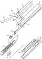
图1为外科缝合器的一个实施方案的透视图;Figure 1 is a perspective view of one embodiment of a surgical stapler;
图2为图1的外科缝合器的远侧部分的分解图;Figure 2 is an exploded view of the distal portion of the surgical stapler of Figure 1;
图3为图1的外科缝合器的击发杆的透视图;Figure 3 is a perspective view of the firing rod of the surgical stapler of Figure 1;
图4为外科缝合器的另一个实施方案的透视图;Figure 4 is a perspective view of another embodiment of a surgical stapler;
图5为外科缝合器的下钳口构件的顶视图,其示出了设置在其上的附属物的一部分;5 is a top view of a lower jaw member of a surgical stapler showing a portion of an appendage disposed thereon;
图6为具有附属物释放机构的单个钉驱动器的透视图;Figure 6 is a perspective view of a single staple driver with an appendage release mechanism;
图7为具有附属物释放机构的双钉驱动器的透视图;并且Figure 7 is a perspective view of a dual staple driver with an appendage release mechanism; and
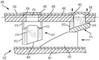
图8为具有附属物释放机构的外科缝合器的下钳口构件的一部分的另一个实施方案的横截面侧视图。8 is a cross-sectional side view of another embodiment of a portion of a lower jaw member of a surgical stapler having an appendage release mechanism.
具体实施方式Detailed ways
现在将描述某些示例性实施方案,以提供对本文所公开的装置和方法的结构、功能、制造和用途的原理全面理解。这些实施方案的一个或多个示例在附图中示出。本领域的技术人员将会理解,在本文中具体描述的和在附图中示出的装置、系统和方法是非限制性的示例性实施方案,并且本发明的范围仅由权利要求书限定。结合一个示例性实施方案示出或描述的特征部可与其它实施方案的特征部进行组合。此类修改和变型旨在包括在本发明的范围之内。Certain exemplary embodiments will now be described to provide a general understanding of the principles of the structure, function, manufacture and use of the devices and methods disclosed herein. One or more examples of these implementations are illustrated in the accompanying drawings. Those skilled in the art will appreciate that the devices, systems and methods specifically described herein and illustrated in the accompanying drawings are non-limiting exemplary embodiments and that the scope of the present invention is defined only by the claims. Features shown or described in connection with one exemplary embodiment may be combined with features of other embodiments. Such modifications and variations are intended to be included within the scope of the present invention.
此外,在本公开中,各实施方案中名称相似的部件通常具有类似的特征部,因此在具体实施方案中,不一定完整地阐述每个名称相似的部件的每个特征部。另外,在所公开的系统、装置和方法的描述中使用线性或圆形尺寸的程度上,此类尺寸并非旨在限制可结合此类系统、装置和方法使用的形状的类型。本领域中技术人员将认识到,针对任何几何形状可容易地确定此类线性和圆形尺寸的等效尺寸。系统和装置及其部件的大小和形状可至少取决于系统和装置将用于其中的受治疗者的解剖结构、系统和装置将与其一起使用的部件的大小和形状、以及系统和装置将用于其中的方法和规程。Furthermore, in the present disclosure, like-named components generally have similar features in various embodiments, and thus not necessarily every feature of each like-named component is fully set forth in a particular embodiment. Additionally, to the extent linear or circular dimensions are used in the description of the disclosed systems, devices and methods, such dimensions are not intended to limit the types of shapes that may be used in connection with such systems, devices and methods. Those skilled in the art will recognize that equivalents to such linear and circular dimensions can be readily determined for any geometry. The size and shape of the systems and devices and their components may depend at least on the anatomy of the subject in which the systems and devices will be used, the size and shape of the components with which the systems and devices will be used, and the methods and procedures therein.
应当理解,本文相对于抓握器械柄部的用户诸如临床医生来使用术语“近侧”和“远侧”。诸如“前”和“后”的其他空间术语分别类似地对应于远侧和近侧。还应当理解,为便利和清楚起见,本文结图示使用空间用语诸如“竖直”和“水平”。然而,外科器械在许多取向和位置上使用,并且这些空间术语并非限制性和绝对的。It should be understood that the terms "proximal" and "distal" are used herein with respect to a user, such as a clinician, grasping the handle of the instrument. Other spatial terms such as "anterior" and "posterior" similarly correspond to distal and proximal, respectively. It should also be understood that spatial terms such as "vertical" and "horizontal" are used in this context for convenience and clarity. However, surgical instruments are used in many orientations and positions, and these spatial terms are not limiting and absolute.
在一些实施方案中,本文所述的装置和方法被设置成用于开放式外科手术,并且在其他实施方案中,该装置和方法设置用于腹腔镜式、内窥镜式和其他微创外科手术。这些装置可由人类用户直接击发或在机器人或类似操纵工具的直接控制下远程击发。然而,本领域的技术人员将理解,本文所公开的各种方法和装置可用于许多外科手术和应用中。本领域的技术人员将进一步理解,本文所公开的各种器械可以任何方式插入到身体中,诸如通过自然孔口、通过在组织中形成的切口或穿孔、或通过进入装置(诸如套管针插管)。例如,该器械的工作部分或端部执行器部分可直接插入到患者的身体中或者可通过进入装置插入,该进入装置具有外科器械的端部执行器和细长轴可推进穿过的工作通道。In some embodiments, the devices and methods described herein are configured for use in open surgical procedures, and in other embodiments, the devices and methods are configured for use in laparoscopic, endoscopic, and other minimally invasive surgeries Operation. These devices may be fired directly by a human user or remotely under the direct control of a robot or similar manipulator. However, those skilled in the art will appreciate that the various methods and devices disclosed herein can be used in many surgical procedures and applications. Those skilled in the art will further appreciate that the various instruments disclosed herein may be inserted into the body in any manner, such as through a natural orifice, through an incision or perforation made in tissue, or through an access device such as a trocar Tube). For example, the working or end effector portion of the instrument may be inserted directly into the patient's body or may be inserted through an access device having a working channel through which the end effector of the surgical instrument and the elongated shaft may be advanced .
本文描述了用于将附属物可释放地保持在外科器械的端部执行器上的各种示例性装置、系统和方法。在一些具体实施中,附属物可以减小或防止附属物过早从钳口滑脱的方式可释放地保持在端部执行器的钳口上。以这种方式,当外科医生在外科手术期间操纵端部执行器时,附属物可牢固地联接到端部执行器。附属物可以多种方式联接到端部执行器,例如通过将附属物的部分插入到钳口的面向组织表面上的连接腔中。在一些实施方案中,附属物可具有标签或突起,其从面向外的表面延伸,使得标签可被构造成接收在钳口的面向组织表面上的腔中。在其他具体实施中,可使用粘合剂将附属物联接到钳口的面向组织表面。附属物可保持联接到端部执行器,直到其与端部执行器分离并转移到患者的身体中的治疗部位,例如通过包括被构造成用于将附属物可释放地附接到其上的特征结构和/或部件的释放机构。可使用多种释放机构,诸如使附属物与端部执行器分离的钉部署构件和/或切割元件。因此,释放机构可允许用户将附属物牢固地附接到端部执行器并且允许用户在需要时快速地部署附属物。Various exemplary devices, systems, and methods for releasably retaining an appendage on an end effector of a surgical instrument are described herein. In some implementations, the appendage can be releasably retained on the jaws of the end effector in a manner that reduces or prevents premature slippage of the appendage from the jaws. In this manner, the appendage can be securely coupled to the end effector as the surgeon manipulates the end effector during a surgical procedure. The appendage can be coupled to the end effector in a variety of ways, such as by inserting portions of the appendage into connection lumens on the tissue-facing surface of the jaws. In some embodiments, the appendage can have a tab or protrusion extending from the outwardly facing surface such that the tab can be configured to be received in a cavity on the tissue facing surface of the jaws. In other implementations, an adhesive can be used to couple the appendage to the tissue-facing surface of the jaws. The appendage can remain coupled to the end effector until it is detached from the end effector and transferred to the treatment site in the patient's body, for example by including a device configured to releasably attach the appendage thereto. Release mechanism for features and/or components. Various release mechanisms may be used, such as staple deployment members and/or cutting elements that separate the appendage from the end effector. Thus, the release mechanism may allow the user to securely attach the appendage to the end effector and allow the user to quickly deploy the appendage if desired.
本文所公开的附属物附接和释放技术可与多种外科器械诸如外科缝合器结合使用。可使用各种外科缝合器,例如线性外科缝合器和圆形缝合器。通常,线性缝合器可被构造成能够产生纵向钉线并且可包括细长钳口,该细长钳口具有联接到其的容纳纵向钉排的仓。缝合器可包括击发杆,该击发杆被构造成将钉驱动到接合在钳口之间的组织中。击发杆可包括能够沿保持在钳口内的组织在钉排之间产生切口的刀或其他切割元件。缝合器可在多种组织上使用,例如在胸腔外科手术或胃外科手术中。The appendage attachment and release techniques disclosed herein can be used in conjunction with a variety of surgical instruments, such as surgical staplers. Various surgical staplers are available, such as linear surgical staplers and circular staplers. In general, linear staplers may be configured to produce a longitudinal staple line and may include an elongated jaw having a cartridge coupled thereto to receive a row of longitudinal staples. The stapler may include a firing bar configured to drive staples into engaged tissue between the jaws. The firing bar may include a knife or other cutting element capable of making an incision between the rows of staples along tissue held within the jaws. The stapler can be used on a variety of tissues, for example in thoracic surgery or gastric surgery.
图1示出了线性外科缝合器10的一个示例。缝合器10通常包括柄部组件12、从柄部组件12的远侧端部12d朝远侧延伸的轴14,以及位于轴14的远侧端部14d处的端部执行器30。端部执行器30具有相对的下钳口32和上钳口34,但其他类型的端部执行器可与轴14、柄部组件12、以及与其相关联的部件一起使用。如图2所示,下钳口32具有被构造成能够支撑钉仓40的钉通道56(参见图2),并且上钳口34具有面向下钳口32并被构造成能够作为砧座操作以帮助部署钉仓40的钉的砧座表面33(钉在图1和图2中被遮挡)。该相对的下钳口32和上钳口34中的至少一者能够相对于下钳口32和上钳口34中的另一者运动以夹紧设置在其间的组织和/或其他对象。在一些具体实施中,该相对的下钳口32和上钳口34中的至少一者可以是固定的或以其他方式不可动的。在一些具体实施中,该相对的下钳口32和上钳口34两者可以是可动的。击发系统的部件可被构造成能够穿过端部执行器30的至少一部分以将钉射出到被夹紧的组织中。在各种具体实施中,刀片36(参见图3)或其他切割元件可与击发系统相关联以在缝合手术期间切割组织。切割元件可被构造成与被射出的钉至少部分地同时切割组织。在一些情况下,如果在钉已被射出并且组织被固定之后切割组织,则可以是有利的。因此,如果外科手术要求切断被捕获在钳口之间的组织,则推进刀片36以切断在钉已从钉仓40射出之后抓持在钳口之间的组织。One example of a linear
端部执行器30的操作可开始于用户(例如,临床医生、外科医生等)在柄部组件12处的输入。柄部组件12可具有被设计成操纵和操作与其相关联的端部执行器30的许多不同的构造。在所示示例中,柄部组件12具有手枪抓握型外壳18,该手枪抓握型外壳具有设置在其中的各种机械和/或电子部件以操作器械10的各种特征结构。例如,柄部组件12可包括与其远侧端部12d相邻安装的旋钮26,该旋钮可有利于轴14和/或端部执行器30围绕轴14的纵向轴线L相对于柄部组件12的旋转。柄部组件12还可包括作为由夹紧触发器22致动的夹紧系统的一部分的夹紧部件和作为由击发触发器24致动的击发系统的一部分的击发部件。夹紧触发器22和击发触发器24可例如由扭力弹簧偏压到相对于固定柄部20的打开位置。夹紧触发器22朝向固定柄部20的运动可致动夹紧系统,如下文所述,其可使钳口32、34朝向彼此塌缩并由此将组织夹紧在它们之间。击发触发器24的运动可致动击发系统,如下所述,其可使钉从其所设置于其中的钉仓40射出和/或使刀片36推进以切断捕获在钳口32、34之间的组织。本领域的技术人员将认识到,可使用用于击发系统的各种构造(机械、液压、气动、机电、机器人或其他)的部件来射出钉和/或切割组织。Operation of
如图2所示,所示具体实施的端部执行器30具有用作仓组件或携载件的下钳口32和用作砧座的相对的上钳口34。在其中具有多个钉的钉仓40支撑在钉托盘37中,该钉托盘继而支撑在下钳口32的仓通道内。上钳口34具有多个钉成形凹坑(未示出),该钉成形凹坑中的每个定位在来自接收在钉仓40内的多个钉的对应钉的上面。尽管在所示具体实施中,上钳口34仅在其与轴14的接合的远侧具有近侧枢转端部34p,该近侧枢转端部可枢转地接收在钉通道56的近侧端部56p内,但上钳口34可以各种方式连接到下钳口32。当上钳口34向下枢转时,上钳口34使砧面33移动,并且形成在其上的钉成形凹坑朝向相对的钉仓40移动。As shown in FIG. 2, the
各种夹紧部件可用于实现钳口32、34的打开和闭合,以选择性地将组织夹紧在钳口32、34之间。如图所示,上钳口34的枢转端部34p在其与钉通道56的枢转附接部的远侧包括闭合特征结构34c。因此,响应于夹紧触发器22,闭合管46选择性地在闭合管46朝近侧纵向运动期间赋予上钳口34打开动作并且在闭合管朝远侧纵向运动期间赋予上钳口34闭合动作,该闭合管的远侧端部包括接合闭合特征结构34c的马蹄形孔46a。如上所述,在各种具体实施中,端部执行器30的打开和闭合可通过下钳口32相对于上钳口34的相对动作、上钳口34相对于下钳口32的相对动作或通过钳口32,34两者相对于彼此的动作来实现。Various gripping components may be used to effect opening and closing of the
所示具体实施的击发部件包括如图3所示的在其远侧端部上具有电子束38的击发杆35。击发杆35包含在轴14内,例如,在轴14的纵向击发杆槽14s中,并且由来自柄部12的击发动作引导。击发触发器24的致动可影响电子束38穿过端部执行器30的至少一部分的远侧动作,以借此引起容纳在钉仓40内的钉的击发。如图所示,从电子束38的远侧端部突出的引导件39可接合如图2所示的楔形滑动件47,这继而可将钉驱动器48向上推动穿过形成在钉仓40中的钉腔41。钉驱动器48的向上移动对仓40内的多个钉中的每个施加向上的力,从而抵靠上钳口34的砧面33向上推动钉,并且产生成形钉。The firing member of the embodiment shown includes a firing
除了使得钉击发以外,电子束38还被构造成能够有利于钳口32、34的闭合,上钳口34相对于钉仓40的隔开,和/或捕获在钳口32、34之间的组织的切断。具体地讲,一对顶销和一对底销可接合上钳口和下钳口32、34中的一者或两者,以在击发杆35推进穿过端部执行器30时将钳口32、34朝向彼此压缩。同时,在顶销和底销之间延伸的刀36被构造成能够切断被捕获在钳口32、34之间的组织。In addition to causing the staples to fire, the
在使用时,外科缝合器10可设置在插管或口中并设置在手术部位处。待切割和缝合的组织可放置在外科缝合器10的钳口32、34之间。缝合器10的特征结构可由用户根据需要来操纵以实现钳口32、34在手术部位处以及组织相对于钳口32、34的期望位置。在已实现适当定位之后,可将夹紧触发器22朝向固定柄部20拉动以致动夹紧系统。夹紧触发器22可使夹紧系统的部件工作,使得闭合管46朝远侧推进穿过轴14的至少一部分以引起钳口32、34中的至少一者朝另一者塌缩以夹紧设置在他们之间的组织。然后,可将夹紧触发器24朝固定柄部20拉动以使击发系统的部件操作,使得击发杆35和/或电子束38朝远侧被推进穿过端部执行器30的至少一部分以实现钉的击发并任选地切断捕获在钳口32、34之间的组织。In use,
线性外科缝合器50形式的外科器械的另一个示例如图4所示。缝合器50通常可与图1的缝合器10类似地构造和使用。类似于图1的外科器械10,外科器械50包括柄部组件52以及轴54,该轴从柄部组件朝远侧延伸并在轴的远侧端部上具有用于治疗组织的端部执行器60。端部执行器60的上钳口64和下钳口62被构造成能够将组织捕获在它们之间,通过从设置在下钳口62中的仓66击发钉来缝合组织并且/或者在组织中产生切口。在该具体实施中,轴54的近侧端部上的附接部分67被构造成能够允许轴54和端部执行器60可移除地附接到柄部组件52。具体地讲,附接部分67的配合特征结构68可与柄部组件52的互补配合特征结构71配合。配合特征结构68、71可被构造成能够经由例如卡扣式联接、卡口式联接等联接在一起,但可使用任何数量的互补配合特征结构和任何类型的联接来将轴54可移除地联接到柄部组件52。虽然所示具体实施的整个轴54被构造成能够从柄部组件52拆下,但在一些具体实施中,附接部分67被构造成能够允许轴54的仅远侧部分拆下。轴54和/或端部执行器60的可拆卸联接可允许针对特定手术选择性地附接期望的端部执行器60,和/或针对多个不同的手术再利用柄部组件52。Another example of a surgical instrument in the form of a linear
柄部组件52可具有位于其上的用于操纵和操作端部执行器60的一个或多个特征结构。作为非限制性示例,安装在柄部组件52的远侧端部上的旋钮72可有利于轴54和/或端部执行器60相对于柄部组件52的旋转。柄部组件52可包括作为由可动触发器74致动的夹紧系统的一部分的夹紧部件和作为也可由触发器74致动的击发系统的一部分的击发部件。因此,在一些具体实施中,触发器74朝固定柄部70运动穿过第一动作范围可致动夹紧部件,使得相对的钳口62、64彼此靠近以达到闭合位置。在一些具体实施中,相对的钳口62、24中的仅一个可移动以将钳口62、64移动到闭合位置。触发器74朝固定柄部70进一步运动穿过第二动作范围可致动击发部件,使得钉从钉仓66中射出和/或使刀或其他切割元件(未示出)的推进切断捕获在钳口62、64之间的组织。Handle assembly 52 may have one or more features thereon for steering and operating
外科缝合器械10、50的所示示例仅提供了可与本文提供的公开内容结合使用的许多不同构造和相关使用方法的几个示例。尽管所示出的示例都被构造成用于微创手术,但是应当理解,被构造成用于开放式外科手术的器械(如2007年2月28日提交的标题为“Surgical Stapling Devices That Produce Formed Staples Having DifferentLengths”的美国专利8,317,070中所述的开放式线性缝合器)可与本文提供的公开内容结合使用。所示示例以及外科缝合器、其部件及其相关使用方法的附加示例的更多细节在以下公布中提供:2014年3月26日提交的标题为“Systems And Methods For Controlling ASegmented Circuit”的美国专利公布2015/0277471;2013年2月8日提交的标题为“LayerComprising Deployable Attachment Members”的美国专利8,393,514;2010年9月30日提交的标题为“Selectively Orientable Implantable Fastener Cartridge”的美国专利8,393,514;2007年2月28日提交的标题为“Surgical Stapling Devices That ProduceFormed Staples Having Different Lengths”的美国专利8,317,070;2005年6月21日提交的标题为“Surgical Instrument Incorporating EAP Blocking Lockout Mechanism”的美国专利7,143,925;2013年11月8日提交的标题为“Sealing Materials For Use InSurgical Stapling”的美国专利公布2015/0134077;2013年11月8日提交的标题为“Sealing Materials for Use in Surgical Procedures”;2013年11月8日提交的标题为“Hybrid Adjunct Materials for Use in Surgical Stapling”的美国专利公布2015/0134076;2013年11月8日提交的标题为“Positively Charged Implantable Materialsand Method of Forming the Same”的美国专利公布2015/0133996;2013年11月8日提交的标题为“Tissue Ingrowth Materials and Method of Using the Same”的美国专利公布2015/0129634;2013年11月8日提交的标题为“Hybrid Adjunct Materials for Use inSurgical Stapling”的美国专利公布2015/0133995;2014年3月26日提交的标题为“Surgical Instrument Comprising a Sensor System”的美国专利公布2015/0272575;以及2010年6月4日提交的标题为“Adjunct Materials and Methods of Using Same inSurgical Methods for Tissue Sealing”的美国专利公布2015/0351758,这些专利全文据此以引用方式并入本文。The illustrated examples of
多种不同的附属物可与本文所公开的外科器械一起使用。“附属物”在本文中也被称为“附属材料”或“支撑物”。可能需要结合外科器械使用一种或多种生物材料和/或合成材料(在本文中统称为“附属物”)来帮助改善外科手术。虽然各种不同的外科端部执行器可受益于附属物的使用,但在一些示例性实施方案中,端部执行器可以是外科缝合器。当结合外科缝合器使用时,该一种或多种附属物可设置在缝合器的钳口之间和/或其上、结合到设置在钳口中的钉仓中或以其他方式邻近钉放置。当部署钉时,该一种或多种附属物可与钉一起保持在治疗部位,继而提供许多益处。例如,该一种或多种附属物可增强治疗部位处的组织,防止在治疗部位处被钉撕开或扯裂。如果组织患病、从另一种治疗诸如照射治疗、药剂治疗诸如化学疗法或其他组织性质改变状况愈合,则可能需要组织增强以防止钉撕开组织。在一些情况下,该一种或多种附属物可使钉穿孔部位中和周围的组织运动(例如,肺膨胀、胃肠道扩张等)最小化,这种组织运动可因缝合之后发生的组织变形而发生。本领域的技术人员将认识到,钉穿孔部位可用作应力集中部,并且当其周围的组织处于张力下时,由钉形成的孔的大小将增大。限制这些穿孔部位周围的组织运动可以使孔在张力下可增大至的大小最小化。在一些情况下,该一种或多种附属物可被构造成能够芯吸或吸收进一步促进愈合的有益流体,例如密封剂、血液、粘着剂,并且在一些情况下,该一种或多种附属物被构造成能够降解以形成进一步促进愈合的凝胶,例如密封剂。在一些情况下,该一种或多种附属物可用于帮助密封在钉被植入组织、血管和各种其他对象或身体部分中时由钉形成的孔。该一种或多种附属物也可通过与该一种或多种附属物相关联的任何纤维或股线的间隔、定位和/或取向来影响组织生长。A variety of different appendages can be used with the surgical instruments disclosed herein. "Appendages" are also referred to herein as "appendage materials" or "supports." It may be desirable to use one or more biomaterials and/or synthetic materials (collectively referred to herein as "appendages") in conjunction with surgical instruments to help improve surgical procedures. While a variety of different surgical end effectors may benefit from the use of appendages, in some exemplary embodiments, the end effector may be a surgical stapler. When used in conjunction with a surgical stapler, the one or more appendages may be disposed between and/or on the jaws of the stapler, incorporated into a staple cartridge disposed in the jaws, or otherwise placed adjacent to the staples. The one or more appendages can remain with the staple at the treatment site when the staple is deployed, which in turn provides a number of benefits. For example, the one or more appendages can reinforce tissue at the treatment site, preventing ripping or tearing at the treatment site by staples. If the tissue is diseased, healing from another treatment such as radiation treatment, drug treatment such as chemotherapy, or other tissue property altering conditions, tissue augmentation may be required to prevent the staples from tearing the tissue. In some cases, the one or more appendages can minimize tissue movement (e.g., lung inflation, gastrointestinal tract distension, etc.) in and around the staple puncture site, which can be caused by tissue movement following suture deformation occurs. Those skilled in the art will recognize that the staple puncture site can act as a stress concentrator and that the hole formed by the staple will increase in size when the surrounding tissue is placed under tension. Restricting tissue movement around these perforation sites can minimize the size to which the holes can grow under tension. In some cases, the one or more appendages can be configured to wick or absorb beneficial fluids that further promote healing, such as sealants, blood, adhesives, and in some cases, the one or more The appendages are configured to degrade to form a gel, such as a sealant, that further promotes healing. In some cases, the one or more appendages can be used to help seal holes formed by the staples as they are implanted in tissue, blood vessels, and various other objects or body parts. The one or more appendages may also affect tissue growth through the spacing, positioning and/or orientation of any fibers or strands associated with the one or more appendages.
如上文所指出的那样,提供了用于与外科缝合器械结合使用的各种可植入附属物。该附属物可具有多种构造并且可由多种材料形成。通常,附属物可由膜、泡沫、注塑热塑性塑料、真空热成型材料、纤维结构及其混合物中的一者或多者形成。该附属物还可包括一种或多种生物衍生材料和一种或多种药物。这些材料中的每一者在下文中有更详细地讨论。As noted above, various implantable appendages are provided for use in conjunction with surgical stapling instruments. The appendage can have a variety of configurations and can be formed from a variety of materials. In general, appendages may be formed from one or more of films, foams, injection molded thermoplastics, vacuum thermoformed materials, fibrous structures, and mixtures thereof. The appendages may also include one or more biologically derived materials and one or more drugs. Each of these materials is discussed in more detail below.
附属物可由泡沫形成,诸如闭孔泡沫、开孔泡沫或海绵。可如何制造此类附属物的示例是来自动物衍生的胶原(诸如猪肌腱),其可随后被加工并冻干成泡沫结构。明胶也可被使用并加工成泡沫。各种泡沫附属物的示例在先前提到的2010年9月30日提交的名称为“Selectively Orientable Implantable Fastener Cartridge”的美国专利8,393,514中有进一步描述。The appendages may be formed from foam, such as closed cell foam, open cell foam or sponge. An example of how such appendages can be made is from animal derived collagen such as porcine tendon, which can then be processed and lyophilized into a foam structure. Gelatin can also be used and processed into foam. Examples of various foam appendages are further described in previously mentioned US Patent 8,393,514, filed September 30, 2010, entitled "Selectively Orientable Implantable Fastener Cartridge."
附属物也可由下文讨论的任何合适的材料或其组合形成的膜形成。该膜可包括一个或多个层,每个层可具有不同的降解速率。此外,膜可具有形成在其中的各种区域,例如,能够可释放地保持一种或多种不同形式的药剂的贮存器。可使用一个或多个不同的包衣来密封其中设置有至少一种药剂的贮存器,该包衣可包括可吸收或不可吸收的聚合物。膜可以各种方式形成。例如,其可为挤出的或压缩模制的膜。药剂还可通过非共价相互作用诸如氢键吸附到膜上或结合到膜。Appendages may also be formed from films formed of any suitable material or combination thereof discussed below. The film may comprise one or more layers, each layer may have a different degradation rate. In addition, the membrane may have various regions formed therein, eg, reservoirs capable of releasably retaining one or more different forms of medicament. The reservoir in which the at least one medicament is disposed may be sealed using one or more different coatings, which coatings may comprise absorbable or non-absorbable polymers. Films can be formed in various ways. For example, it may be an extruded or compression molded film. Agents can also adsorb to or bind to membranes through non-covalent interactions such as hydrogen bonding.
附属物也可由注塑热塑性材料或真空热成型材料形成。2013年2月8日提交的名称为“Fastener Cartridge Comprising A Releasably Attached Tissue ThicknessCompensator”的美国专利公布2013/0221065中中进一步描述了各种各种模制附属物的示例,该专利全文以引用方式并入本文。附属物也可以是基于纤维的格,其可以是织造物、针织物或非织造物,诸如熔喷、针刺或热构建的松散织造物。附属物可具有可由相同类型的格或不同类型的格形成的多个区域,这些格可以多种不同的方式一起形成附属物。例如,纤维可织造、编织、针织或以其他方式相互连接以便形成规则或不规则的结构。纤维可相互连接,使得所得的附属物相对松散。另选地,附属物可包括紧密互连的纤维。附属物可以是片材、管材、螺旋或任何其他可包括柔性部分和/或更刚性的增强部分的结构的形式。附属物可被构造成能够使得其某些区域可具有更致密的纤维,而其他区域具有较低密度的纤维。基于附属物的预期应用,纤维密度可沿附属物的一个或多个维度在不同方向上变化。此外,在某些情况下,附属物可用于分配由钉施加的压力,从而减少钉穿过组织(可能易碎)并且不能按预期紧固组织(所谓的“乳酪布线”)的可能性。另外,附属物可至少部分地可拉伸,并且因此可允许组织的至少部分的自然运动(例如,呼吸期间肺组织的扩张和收缩)。在一些实施方案中,钉线可以是柔性的,如例如2014年9月26日提交的标题为“Method forCreating a Flexible Staple Line”的美国专利公布2016/0089142中所述,该公布据此全文以引用方式并入本文。附属物可由织造的、针织的或以其他方式互连的纤维形成,这允许附属物拉伸。例如,附属物可被构造成在沿其纵向轴线的方向上和/或在垂直于纵向轴线的侧向方向上拉伸。虽然在至少两个尺寸(例如,X方向和Y方向)上可拉伸,但是附属物可沿其厚度(例如,在Z方向上)提供加强,使得其拉伸但抵抗钉撕裂和拉扯。被构造成被植入而使得他们可与组织拉伸的附属物的非限制性实例描述于2016年9月24日提交的标题为“Method for Creating a Flexible Staple Line”的上述美国专利公布2016/0089142,该公布据此全文以引用方式并入本文。The appendages may also be formed from injection molded thermoplastic or vacuum thermoformed material. Examples of various molded appendages are further described in U.S. Patent Publication 2013/0221065, entitled "Fastener Cartridge Comprising A Releasably Attached Tissue Thickness Compensator," filed February 8, 2013, which is incorporated by reference in its entirety. into this article. The appurtenance may also be a fiber-based lattice, which may be a woven, knitted or nonwoven, such as melt blown, needle punched or thermally constructed loose weave. Appendices may have multiple regions that may be formed from the same type of cells or different types of cells, which together may form appendages in a number of different ways. For example, fibers may be woven, braided, knitted, or otherwise interconnected to form regular or irregular structures. The fibers can be interconnected so that the resulting appendage is relatively loose. Alternatively, appendages may comprise tightly interconnected fibers. Appendages may be in the form of sheets, tubes, spirals or any other structure which may include flexible portions and/or more rigid reinforcing portions. Appendages may be configured such that certain regions thereof may have denser fibers while other regions have lower density fibers. Fiber density may vary in different directions along one or more dimensions of the appendage based on the intended application of the appendage. Additionally, in some cases, appendages can be used to distribute the pressure exerted by the staples, thereby reducing the likelihood that the staples will pass through tissue (which may be fragile) and fail to fasten tissue as intended (so-called "cheese wiring"). Additionally, the appendages can be at least partially stretchable, and thus can allow at least some natural movement of the tissue (eg, expansion and contraction of lung tissue during breathing). In some embodiments, the staple line can be flexible, as described, for example, in U.S. Patent Publication 2016/0089142, filed September 26, 2014, entitled "Method for Creating a Flexible Staple Line," which publication is hereby incorporated herein by reference in its entirety. Incorporated herein by reference. Appendages may be formed from woven, knitted or otherwise interconnected fibers which allow the appendages to stretch. For example, an appendage may be configured to stretch in a direction along its longitudinal axis and/or in a lateral direction perpendicular to the longitudinal axis. While stretchable in at least two dimensions (e.g., X and Y directions), the appendage can provide reinforcement along its thickness (e.g., in the Z direction) such that it stretches but resists staple tear and pull. Non-limiting examples of appendages configured to be implanted such that they can stretch with tissue are described in the aforementioned U.S. Patent Publication 2016/ 0089142, which publication is hereby incorporated by reference in its entirety.
附属物也可以是混合构建物,诸如层压复合物或熔融互锁纤维。多种混合构造附属物的示例还描述于2013年2月8日提交的标题为“Adhesive Film Laminate”的美国专利9,282,962以及2007年9月12日提交的标题为“Minimally Invasive Medical Implant AndInsertion Device And Method For Using The Same”的美国专利7,601,118,其全文据此以引用方式并入本文。Appendages may also be hybrid constructions such as laminated composites or fused interlocked fibers. Examples of various hybrid construction adjuncts are also described in U.S. Patent 9,282,962, filed February 8, 2013, entitled "Adhesive Film Laminate," and in September 12, 2007, entitled "Minimally Invasive Medical Implant And Insertion Device And Method US Patent 7,601,118 for Using The Same", which is hereby incorporated by reference in its entirety.
根据所述技术的附属物可由各种材料形成。这些材料可用于各种实施方案中以用于不同目的。这些材料可根据待递送至组织的期望治疗来选择以便便于组织的向内生长。这些材料可包括可生物吸收的聚合物和生物相容性聚合物,包括均聚物和共聚物。可生物吸收的聚合物可以是吸收性的、可吸收的、生物可吸收的或可生物降解的聚合物。附属物还可包括活性剂,诸如活性细胞培养物(例如,切块的自体组织、用于干细胞疗法的试剂(例如,Biosutures和Cellerix SL)、止血剂和组织愈合剂)。Appendices according to the described techniques may be formed from a variety of materials. These materials can be used in various embodiments for different purposes. These materials can be selected in order to facilitate tissue ingrowth according to the desired treatment to be delivered to the tissue. These materials can include bioabsorbable polymers and biocompatible polymers, including homopolymers and copolymers. A bioabsorbable polymer can be an absorbent, absorbable, bioabsorbable or biodegradable polymer. Adjuncts may also include active agents such as active cell cultures (eg, excised autologous tissue, reagents for stem cell therapy (eg, Biosutures and Cellerix SL), hemostatic agents, and tissue healing agents).
附属物能够可释放地保持至少一种可选自大量不同药剂的药剂。药剂包括但不限于包含在附属物内或与附属物相关的具有期望功能的药物或其他剂。药剂包括但不限于例如抗微生物剂(诸如抗菌剂和抗生素)、抗真菌剂、抗病毒剂、抗炎剂、生长因子、止痛药、麻醉剂、组织基质退化抑制剂、抗癌剂、止血剂和引发生物反应的其他剂。附属物也可由增强成像期间的可见度的试剂制成或者包括该试剂,诸如例如抗病毒材料或无线不透明材料。The appendage is capable of releasably holding at least one agent that may be selected from a number of different agents. Agents include, but are not limited to, drugs or other agents that have a desired function contained within or associated with an appendage. Agents include, but are not limited to, for example, antimicrobials (such as antibacterials and antibiotics), antifungals, antivirals, anti-inflammatory agents, growth factors, pain relievers, anesthetics, inhibitors of tissue matrix degradation, anticancer agents, hemostatic agents, and Other agents that elicit a biological response. Appendages may also be made of or include agents that enhance visibility during imaging, such as, for example, antiviral materials or wireless opaque materials.
用于从附属物释放药剂的各种附属物和各种技术的示例还描述于2015年8月31日提交的标题为“Medicant Eluting Adjuncts and Methods of Using Medicant ElutingAdjuncts”的美国专利申请14/840,613,该申请全文据此以引用方式并入本文。Examples of various appendages and various techniques for releasing agents from appendages are also described in
如上所述,使用具有各种外科装置诸如外科缝合器的支撑物、附属物和/或药剂可需要从端部执行器的至少一个组织接触表面附接和释放附属物。通过多种技术可实现将附属物附接到端部执行器以及从端部执行器释放附属物。图5-7示出了具有附属物释放机构的端部执行器100的一个实施方案。图5示出了端部执行器100的下钳口101的一部分,其可设置在外科器械诸如上面讨论的外科缝合器10、50的远侧端部上。下钳口101可具有设置在其上的类似于钉仓40的仓102,仓102具有面向组织表面106,其上设置有附属物104(仅示出了附属物104的一部分),诸如上面讨论的支撑物、附属物和/或药剂中的一个或多个。As noted above, use of supports, appendages, and/or agents with various surgical devices, such as surgical staplers, may require attaching and releasing the appendage from at least one tissue-contacting surface of the end effector. Attaching the appendage to the end effector and releasing the appendage from the end effector can be accomplished by a variety of techniques. 5-7 illustrate one embodiment of an
仓102可具有设置在钉腔108中的钉,钉腔108形成在面向组织表面106中。面向组织表面106还可具有通道112,该通道被构造成在其朝远侧移动穿过时接收类似于刀片36的切割元件。一个或多个连接腔110可在钉腔108之间延伸并连接钉腔108,以将附属物连接到仓102。连接腔110可以是凹陷部或孔的形式,并且可具有各种构造和形状。例如,连接腔110可以是大致椭圆形的并且小于钉腔108。在其他实施方案中,腔可以是圆形、正方形、矩形、三维形状等,并且他们的尺寸或尺寸组合可相对于钉腔108较大或相等。腔110可设置在钉腔108的行之间。然而,连接腔110可具有任何数量的构造,诸如每个钉腔108具有与其相邻的连接腔110。虽然连接腔110邻近面向组织表面106上的钉腔108形成,但是他们可在别处形成。例如,腔可形成在仓和类似于托盘37的托盘的界面处,使得腔的内表面的一些部分是仓的表面,而另一部分是托盘的表面。此外,用于附接和分离附属物的连接腔不必限于仓的面向组织表面。例如,连接腔可沿仓的面向组织表面的边缘形成,使得当组装端部执行器时,连接腔的一部分将由类似于钉盘37的钉盘形成。另选地,不是连接腔,而是通道可在仓的面向组织表面和托盘之间形成。附属物的部分可塞入通道中,或者在制造期间或使用前的任何时间粘附到通道的近侧的位置处的面向组织表面。在此类实施方案中,靠近仓的面向组织表面的最外边缘的驱动器可具有附属物释放机构,使得附属物的部分被推出通道,并且/或者在击发期间沿附属物和仓之间的通道破坏粘合剂粘结。
附属物104可被构造成可释放地保持在面向组织表面106上。附属物104可具有设置在与面向组织表面106接触的表面上的突起或突片,并且突起可被构造成延伸到连接腔110中并与连接腔110接合。附属物104可被构造成通过各种方式接合面向组织表面106。例如,附属物上的突起可被接收在连接腔中并且由于摩擦配合附接而牢固地附接。在此类示例中,可通过挤出膜使得其在预定位置具有突起来产生附属物,所述预定位置对应于仓的面向组织表面上的连接腔的位置。在其他实施方案中,辅附属物可由

仓102可具有可移动地设置在其中的类似于钉驱动器48的一个或多个钉驱动器200、300。钉驱动器200、300可被构造成向上移动穿过钉腔108,以对仓102内的多个钉中的每一个施加向上的力。图6中示出的钉驱动器200可具有钉部分202,该钉部分可具有形成在其上端上的钉通道208,并且可被构造成使钉坐置在其中,类似于钉驱动器48。驱动器200还可具有附接到钉部分202的侧面并且具有大致L形的构造的附属物释放机构203。附属物释放机构203可具有将钉部分202连接到附属物释放机构203的连接元件204。柱206可附接到连接元件204,并且其可在与钉部分202的钉通道208相同的方向上向上延伸。连接元件204可具有向上倾斜的底部205,其被构造成接触类似于楔形滑动件47的楔形滑动件,以允许驱动器200的向上移动和钉的击发。柱206可具有各种形状,诸如图6中所示的矩形形状、圆柱形、正方形等。在示例性实施方案中,柱206具有与连接腔110的形状对应的形状,使得柱206可被接收在连接腔110中。
图7示出了钉驱动器300的另一个实施方案,其可被构造成类似于钉驱动器200。然而,钉驱动器300可具有类似于钉部分202的第一钉部分302和第二钉部分303,其中钉通道308、310分别设置在钉部分302、303的上端上。每个钉通道308、310可被构造成使钉坐置在其中,并且钉驱动器300可被构造成同时击发两个钉。第一钉部分302和第二钉部分303可具有联接在两者之间的附属物释放机构304。附属物释放机构304可包括连接元件305和柱306。连接元件305在两个钉部分302、303之间延伸并连接两个钉部分302、303,并且其具有向上倾斜的底部309,其被构造成接触类似于楔形滑动件47的楔形滑动件,以允许驱动器300向上移动和击发钉。柱306附接到连接元件305并且在与钉通道308、310相同的方向上向上延伸。柱306可具有各种形状,诸如图6中所示的矩形形状、圆柱形、正方形等。在示例性实施方案中,柱306具有与连接腔110的形状对应的形状,使得柱306可被接收在连接腔110中。FIG. 7 illustrates another embodiment of a
虽然所示的钉驱动器200、300在钉部分和附属物释放机构之间具有连接元件,但是可使用各种连接来连接多个钉驱动器。例如,两个连接元件可用于连接三个钉驱动器。本领域技术人员将会知道,连接元件可包括多个附属物释放机构,多个连接元件可并联或串联使用以连接多个钉驱动器,并且附属物释放机构可具有任何数量的几何形状。例如,附属物释放机构可以是弯曲的,或者可具有方形,圆形,三角形等的横截面。另外,可能并非所有的附属物释放机构都是均匀的。附属物释放机构也可具有尖锐的特征结构。例如,可使分离特征结构变尖锐,使得他们可切除附属物的一小部分以将其余部分与仓的面向组织表面分离。While the
在使用中,钉驱动器200和/或300可设置在仓102中并与钉腔108和连接腔110对齐,使得钉通道208、308、310与钉腔108对齐,并且柱206、306与连接腔110对齐。仓102可装载有钉。附属物104可通过例如摩擦配合在连接腔110内的多个突起而保持在面向组织表面106上。附属物104可在使用之前的任何时间施加到面向组织表面106,诸如在制造期间或在准备使用期间,并且可通过各种技术诸如通过使用施加器施加。In use,
外科医生可将外科缝合器操纵到适当位置并将组织夹紧在端部执行器100的钳口之间。然后外科医生可击发外科缝合器,使得类似于楔形滑动件47的滑动件朝远侧移动穿过端部执行器100的仓102。滑动件可将钉驱动器200、300中的一个或多个向上推动穿过仓102中的钉腔108。钉驱动器200、300的向上移动对仓102内的多个钉中的每一个施加向上的力,从而将钉向上推动穿过附属物104和组织并抵靠端部执行器100的上钳口的砧面以形成钉。钉驱动器200、300的向上移动也使柱206、306向上移动。柱206、306在附属物104的突起上施加向上的力,从而在柱206、306的远侧端部进入腔110时迫使突起离开连接腔110。迫使来自腔110的突起从面向组织表面106释放附属物104,并且附属物可通过钉固定到由端部执行器100抓持的组织。在其他实施方案中,柱206、306可被构造成仅部分地迫使突起部分离开连接腔110,这可足以使附属物104从面向组织表面106充分松开,使得钉将在击发时完全移除附属物104。在各种实施方案中,击发外科缝合器还可使得切割元件沿通道112平移穿过仓102到达组织,同时钉被击发并且附属物104被释放。The surgeon can maneuver the surgical stapler into position and clamp tissue between the jaws of the
虽然附属物104可通过突起附接到仓102,但如上所述,附属物可通过各种方式附接到外科缝合器的仓。例如,图8示出了端部执行器400,其具有仓402和通过粘合剂固定到其上的附属物404。端部执行器400通常可起作用并包括与端部执行器100类似的部件。例如,端部执行器400可包括具有砧座(未示出)的上钳口和具有接合在其上的仓402的下钳口401。While the
仓402可具有设置在多个钉腔408中的钉416以及形成在面向组织表面406中的多个连接腔410。连接腔410可具有各种构造和形状。例如,连接腔410可以是大致椭圆形的并且小于钉腔408。在其他实施方案中,连接腔410可以是圆形、方形、矩形等,并且他们的尺寸或尺寸组合可相对于钉腔108较大或相等。连接腔410可设置在钉腔408的行之间。然而,连接腔410可具有任何数量的构造。
附属物404可被构造成可释放地保持在面向组织表面406上,并且附属物404可以是本文所讨论的附属物中的任一个。附属物404可具有设置在与面向组织表面406接触的表面上的粘合剂。例如,在附属物404和面向组织表面406之间可在连接腔410的外边缘周围存在粘合点405,其可被构造成将附属物404保持在仓402上。然而,粘合点405的各种不同放置是可能的,诸如以网格图案。另外,粘合剂可均匀地散布在面向组织表面406上。可使用各种粘合剂,诸如氰基丙烯酸酯。
当附属物用粘合剂附接到仓时,在各种实施方案中可能希望防止粘合剂溢出到仓中,例如进入切割元件通道或进入钉腔。各种附属物可被构造成包括在附接过程期间防止或抑制粘合剂溢出到仓中和/或特别是仓的切割元件通道的特征结构。作为示例,粘合点405可通过在附属物404的表面上包括小圆形模制特征结构而形成,该表面接触仓404的面向组织表面406。圆形模制特征结构可用作贮存器以形成粘合剂液滴附接点,从而确保粘合剂诸如氰基丙烯酸酯在附接期间不会进入仓402和/或切割元件通道。在其他实施方案中,粘合剂可容纳在附属物本身内,或者用于粘合剂的贮存器可以是用于将附属物施加到仓的施加器的一部分。例如,贮存器可作为夹紧或拉动施加器上的致动杆的一部分而被破坏。When the appendage is attached to the cartridge with adhesive, in various embodiments it may be desirable to prevent the adhesive from spilling into the cartridge, for example into the cutting element channel or into the staple cavities. Various appendages can be configured to include features that prevent or inhibit adhesive spillage into the cartridge and/or particularly the cutting element channel of the cartridge during the attachment process. As an example,
仓402可具有可移动地设置在其中的类似于钉驱动器200、300的一个或多个钉驱动器411,其可被构造成向上移动穿过钉腔408以对钉仓402内的多个钉416中的每一个施加向上的力。每个钉驱动器411可具有钉部分412,该钉部分412可具有形成在其上端上的钉通道413,该钉通道413被构造成使钉416坐置在其中。驱动器411还可具有附属物释放机构,该附属物释放机构附接到钉部分412的侧面并且具有柱414,该柱414附接到钉部分412并且在与钉部分412的钉通道413相同的方向上向上延伸。钉驱动器411可具有向上倾斜的底部409,其被构造成接收类似于楔形滑动件47的楔形滑动件420,以允许驱动器200的向上移动和钉的击发。柱414可具有各种形状,诸如矩形、圆柱形、方形等,并且柱406可被构造成被接收在连接腔410中。
在使用中,仓402可具有设置在其中并装载有钉416的多个钉驱动器411。附属物404可通过例如在附属物404和面向组织表面406之间围绕连接腔410的外边缘具有多个粘合点405而保持在面向组织表面406上。附属物404可在使用之前的任何时间施加到面向组织表面406,诸如在制造期间或在准备使用期间,并且可通过各种技术诸如通过使用施加器施加。外科医生可将外科缝合器操纵到适当位置并将组织夹紧在端部执行器400的钳口之间。然后外科医生可击发外科缝合器,使得滑动件420朝远侧移动穿过端部执行器400的仓402。滑动件420可向上推动钉驱动器411中的一个或多个穿过钉仓402中的钉腔408。钉驱动器411的向上移动对仓402内的多个钉416中的每一个施加向上的力,从而将钉向上推动穿过附属物404和组织并抵靠端部执行器400的上钳口的砧面以形成钉。钉驱动器411的向上移动还使柱414向上移动。柱414可在附属物404上施加向上的力,从而一旦柱414充分移动穿过连接腔411,就迫使附属物404向上移动并且破坏粘合点405。例如,粘合点405可保持牢固,直到柱414的最远侧端部穿过面向组织表面406的平面。粘合点405从附属物404和面向组织表面406之间破坏、破裂或分离将附属物404从面向组织表面406释放,并且附属物404可通过钉416固定到由端部执行器400抓持的组织。尽管柱414的最远侧端部可穿过面向组织表面406的平面,但是柱414可被构造成使得他们仅在面向组织表面406处或下方延伸。在一些实施方案中,击发外科缝合器还可使切割元件平移穿过钉仓402,从而在钉416被击发并且释放附属物404时切割组织。In use, the
虽然可如上文所示将附属物附接到下钳口,但是附属物也可附接到上钳口的部件诸如砧座。上钳口可类似于图1-2中所示的上钳口,但是可包括用于附接和分离附属物的特征结构和/或部件。例如,上钳口可被构造成包括由E梁驱动的连接腔和驱动器,以使附属物与钳口分离。在各种实施方案中,当开始缝合时,下钳口的部件可用于驱动钉穿过组织和附属物,而上钳口中的驱动器可用于将附属物与砧座分离。While the appendage can be attached to the lower jaw as shown above, the appendage can also be attached to a component of the upper jaw, such as the anvil. The upper jaw may be similar to the upper jaw shown in FIGS. 1-2, but may include features and/or components for attaching and detaching appendages. For example, the upper jaw may be configured to include a coupling chamber and driver actuated by an E-beam to detach the appendage from the jaw. In various embodiments, when suturing is initiated, components of the lower jaw can be used to drive the staples through the tissue and appendage, while drivers in the upper jaw can be used to separate the appendage from the anvil.
本文所公开的装置可被设计成在单次使用后废弃,或者其可被设计成多次使用。然而无论是哪种情况,该装置都可在至少使用一次后经过修整再行使用。修整可包括拆卸装置、之后清洁或替换特定零件以及后续重新组装步骤的任意组合。具体地,所述装置可拆卸,而且可以任意组合选择性地替换或移除所述装置的任意数目的特定零件或部件。在清洁和/或替换特定部件后,可对所述装置进行重新组装,以便随后在修整设施处使用或就在外科手术之前由手术团队使用。本领域的技术人员将会理解,修整装置可利用各种技术来进行拆卸、清洁/替换和重新组装。此类技术的使用以及所得的修复装置均在本申请的范围内。The devices disclosed herein can be designed to be discarded after a single use, or they can be designed to be used multiple times. In either case, however, the device can be reconditioned for reuse after at least one use. Reconditioning may include any combination of disassembly of the device, subsequent cleaning or replacement of specific parts, and subsequent reassembly steps. In particular, the device is detachable and any number of specific parts or components of the device can be selectively replaced or removed in any combination. After cleaning and/or replacement of certain components, the device can be reassembled for subsequent use at a reconditioning facility or by a surgical team just prior to a surgical procedure. Those skilled in the art will appreciate that the conditioning device can be disassembled, cleaned/replaced and reassembled using various techniques. The use of such techniques, as well as the resulting prosthetic devices, are within the scope of this application.
根据上述实施方案,本领域中技术人员将会认识到本发明的另外的特征和优点。因此,本发明不应受到已具体示出和描述内容的限制,除非所附权利要求有所指示。本文引用的所有出版物和参考文献全文明确地以引用方式并入本文中。From the above-described embodiments, those skilled in the art will recognize additional features and advantages of the present invention. Accordingly, the invention is not to be limited by what has been particularly shown and described, except as indicated by the appended claims. All publications and references cited herein are expressly incorporated by reference in their entirety.
Claims (5)
Applications Claiming Priority (3)
| Application Number | Priority Date | Filing Date | Title |
|---|---|---|---|
| US15/436,070US10478183B2 (en) | 2017-02-17 | 2017-02-17 | Adjunct release for surgical staplers |
| US15/436,070 | 2017-02-17 | ||
| PCT/US2018/017972WO2018152096A1 (en) | 2017-02-17 | 2018-02-13 | Adjunct release for surgical staplers |
Publications (2)
| Publication Number | Publication Date |
|---|---|
| CN110366390A CN110366390A (en) | 2019-10-22 |
| CN110366390Btrue CN110366390B (en) | 2023-01-20 |
Family
ID=61231117
Family Applications (1)
| Application Number | Title | Priority Date | Filing Date |
|---|---|---|---|
| CN201880012695.1AActiveCN110366390B (en) | 2017-02-17 | 2018-02-13 | Adjunct release for surgical stapler |
Country Status (5)
| Country | Link |
|---|---|
| US (1) | US10478183B2 (en) |
| EP (2) | EP3363373B1 (en) |
| JP (1) | JP7046964B2 (en) |
| CN (1) | CN110366390B (en) |
| WO (1) | WO2018152096A1 (en) |
Families Citing this family (56)
| Publication number | Priority date | Publication date | Assignee | Title |
|---|---|---|---|---|
| US10716564B2 (en) | 2017-02-17 | 2020-07-21 | Ethicon Llc | Stapling adjunct attachment |
| CA3090020A1 (en) | 2018-03-02 | 2019-09-06 | Covidien Lp | Surgical stapling instrument |
| US11707274B2 (en) | 2019-12-06 | 2023-07-25 | Covidien Lp | Articulating mechanism for surgical instrument |
| US11452524B2 (en) | 2020-01-31 | 2022-09-27 | Covidien Lp | Surgical stapling device with lockout |
| US12156651B2 (en) | 2020-02-03 | 2024-12-03 | Covidien Lp | Surgical stapling device |
| CN115103642A (en) | 2020-02-14 | 2022-09-23 | 柯惠有限合伙公司 | surgical stapler |
| JP2023523507A (en) | 2020-02-14 | 2023-06-06 | コヴィディエン リミテッド パートナーシップ | A cartridge holder for surgical staples and having ridges on the peripheral wall for gripping tissue |
| US11406383B2 (en) | 2020-03-17 | 2022-08-09 | Covidien Lp | Fire assisted powered EGIA handle |
| US12108953B2 (en) | 2020-03-24 | 2024-10-08 | Covidien Lp | Surgical stapling device with replaceable staple cartridge |
| US11937794B2 (en) | 2020-05-11 | 2024-03-26 | Covidien Lp | Powered handle assembly for surgical devices |
| US12349902B2 (en) | 2020-07-09 | 2025-07-08 | Covidien Lp | Powered handle assembly for surgical devices |
| EP4185215A4 (en) | 2020-07-21 | 2024-04-03 | Covidien LP | Shipping cover for staple cartridge |
| US11602342B2 (en) | 2020-08-27 | 2023-03-14 | Covidien Lp | Surgical stapling device with laser probe |
| US11678878B2 (en) | 2020-09-16 | 2023-06-20 | Covidien Lp | Articulation mechanism for surgical stapling device |
| US11660092B2 (en) | 2020-09-29 | 2023-05-30 | Covidien Lp | Adapter for securing loading units to handle assemblies of surgical stapling instruments |
| US11406384B2 (en) | 2020-10-05 | 2022-08-09 | Covidien Lp | Stapling device with drive assembly stop member |
| US11576674B2 (en) | 2020-10-06 | 2023-02-14 | Covidien Lp | Surgical stapling device with articulation lock assembly |
| US11890007B2 (en) | 2020-11-18 | 2024-02-06 | Covidien Lp | Stapling device with flex cable and tensioning mechanism |
| US11737774B2 (en) | 2020-12-04 | 2023-08-29 | Covidien Lp | Surgical instrument with articulation assembly |
| US11819200B2 (en) | 2020-12-15 | 2023-11-21 | Covidien Lp | Surgical instrument with articulation assembly |
| US11553914B2 (en) | 2020-12-22 | 2023-01-17 | Covidien Lp | Surgical stapling device with parallel jaw closure |
| WO2022140080A1 (en) | 2020-12-23 | 2022-06-30 | Covidien Lp | Surgical instrument including a decoupling mechanism |
| US11759206B2 (en) | 2021-01-05 | 2023-09-19 | Covidien Lp | Surgical stapling device with firing lockout mechanism |
| US11744582B2 (en) | 2021-01-05 | 2023-09-05 | Covidien Lp | Surgical stapling device with firing lockout mechanism |
| US11517313B2 (en) | 2021-01-27 | 2022-12-06 | Covidien Lp | Surgical stapling device with laminated drive member |
| US11759207B2 (en) | 2021-01-27 | 2023-09-19 | Covidien Lp | Surgical stapling apparatus with adjustable height clamping member |
| US11717300B2 (en) | 2021-03-11 | 2023-08-08 | Covidien Lp | Surgical stapling apparatus with integrated visualization |
| US11974750B2 (en) | 2021-03-26 | 2024-05-07 | Covidien Lp | Surgical staple cartridge |
| US11497495B2 (en) | 2021-03-31 | 2022-11-15 | Covidien Lp | Continuous stapler strip for use with a surgical stapling device |
| US11666330B2 (en) | 2021-04-05 | 2023-06-06 | Covidien Lp | Surgical stapling device with lockout mechanism |
| US20220346781A1 (en)* | 2021-04-30 | 2022-11-03 | Cilag Gmbh International | Staple cartridge comprising staple drivers and stability supports |
| US11576670B2 (en) | 2021-05-06 | 2023-02-14 | Covidien Lp | Surgical stapling device with optimized drive assembly |
| US11812956B2 (en) | 2021-05-18 | 2023-11-14 | Covidien Lp | Dual firing radial stapling device |
| US11696755B2 (en) | 2021-05-19 | 2023-07-11 | Covidien Lp | Surgical stapling device with reload assembly removal lockout |
| CN117337154A (en) | 2021-05-21 | 2024-01-02 | 柯惠有限合伙公司 | Articulated assemblies for surgical devices |
| US11771423B2 (en) | 2021-05-25 | 2023-10-03 | Covidien Lp | Powered stapling device with manual retraction |
| US11510673B1 (en) | 2021-05-25 | 2022-11-29 | Covidien Lp | Powered stapling device with manual retraction |
| US11701119B2 (en) | 2021-05-26 | 2023-07-18 | Covidien Lp | Powered stapling device with rack release |
| US11576675B2 (en) | 2021-06-07 | 2023-02-14 | Covidien Lp | Staple cartridge with knife |
| US11707275B2 (en) | 2021-06-29 | 2023-07-25 | Covidien Lp | Asymmetrical surgical stapling device |
| US11617579B2 (en) | 2021-06-29 | 2023-04-04 | Covidien Lp | Ultra low profile surgical stapling instrument for tissue resections |
| US11602344B2 (en) | 2021-06-30 | 2023-03-14 | Covidien Lp | Surgical stapling apparatus with firing lockout assembly |
| US11540831B1 (en) | 2021-08-12 | 2023-01-03 | Covidien Lp | Staple cartridge with actuation sled detection |
| US11779334B2 (en) | 2021-08-19 | 2023-10-10 | Covidien Lp | Surgical stapling device including a manual retraction assembly |
| US12023028B2 (en) | 2021-08-20 | 2024-07-02 | Covidien Lp | Articulating surgical stapling apparatus with pivotable knife bar guide assembly |
| US11707277B2 (en) | 2021-08-20 | 2023-07-25 | Covidien Lp | Articulating surgical stapling apparatus with pivotable knife bar guide assembly |
| US11576671B1 (en) | 2021-08-20 | 2023-02-14 | Covidien Lp | Small diameter linear surgical stapling apparatus |
| US11864761B2 (en) | 2021-09-14 | 2024-01-09 | Covidien Lp | Surgical instrument with illumination mechanism |
| US11660094B2 (en) | 2021-09-29 | 2023-05-30 | Covidien Lp | Surgical fastening instrument with two-part surgical fasteners |
| US11653922B2 (en) | 2021-09-29 | 2023-05-23 | Covidien Lp | Surgical stapling device with firing lockout mechanism |
| US11849949B2 (en) | 2021-09-30 | 2023-12-26 | Covidien Lp | Surgical stapling device with firing lockout member |
| US12035909B2 (en) | 2021-10-13 | 2024-07-16 | Covidien Lp | Surgical stapling device with firing lockout mechanism |
| US12268389B2 (en) | 2021-11-12 | 2025-04-08 | Covidien Lp | Surgical stapling device with firing lockout |
| CN217118490U (en) | 2021-12-17 | 2022-08-05 | 天臣国际医疗科技股份有限公司 | staple cartridge assembly and medical stapler |
| US12137905B2 (en) | 2022-05-16 | 2024-11-12 | Covidien Lp | Gas-powered continuous feed surgical fastening device |
| US12193666B2 (en) | 2022-05-27 | 2025-01-14 | Covidien Lp | Replaceable staple cartridge with retractable knife |
Citations (3)
| Publication number | Priority date | Publication date | Assignee | Title |
|---|---|---|---|---|
| CN102319093A (en)* | 2007-06-22 | 2012-01-18 | Tyco医疗健康集团 | The separable buttress material retention systems that is used for surgical stapling apparatus |
| CN103841902A (en)* | 2011-10-03 | 2014-06-04 | 伊西康内外科公司 | Attachment of surgical staple buttress to cartridge |
| JP2014518682A (en)* | 2011-04-29 | 2014-08-07 | エシコン・エンド−サージェリィ・インコーポレイテッド | Staple cartridge mounting assembly |
Family Cites Families (22)
| Publication number | Priority date | Publication date | Assignee | Title |
|---|---|---|---|---|
| AU2005269338B2 (en) | 2004-07-28 | 2012-02-02 | Ethicon, Inc. | Minimally invasive medical implant and insertion device and method for using the same |
| US7143925B2 (en) | 2004-07-28 | 2006-12-05 | Ethicon Endo-Surgery, Inc. | Surgical instrument incorporating EAP blocking lockout mechanism |
| US7673781B2 (en) | 2005-08-31 | 2010-03-09 | Ethicon Endo-Surgery, Inc. | Surgical stapling device with staple driver that supports multiple wire diameter staples |
| US7506791B2 (en)* | 2006-09-29 | 2009-03-24 | Ethicon Endo-Surgery, Inc. | Surgical stapling instrument with mechanical mechanism for limiting maximum tissue compression |
| US9585657B2 (en) | 2008-02-15 | 2017-03-07 | Ethicon Endo-Surgery, Llc | Actuator for releasing a layer of material from a surgical end effector |
| US20090206141A1 (en)* | 2008-02-15 | 2009-08-20 | Ethicon Endo-Surgery, Inc. | Buttress material having an activatable adhesive |
| US9113862B2 (en) | 2010-09-30 | 2015-08-25 | Ethicon Endo-Surgery, Inc. | Surgical stapling instrument with a variable staple forming system |
| US9788834B2 (en) | 2010-09-30 | 2017-10-17 | Ethicon Llc | Layer comprising deployable attachment members |
| US9999408B2 (en) | 2011-09-14 | 2018-06-19 | Ethicon Endo-Surgery, Inc. | Surgical instrument with fluid fillable buttress |
| US20140048580A1 (en) | 2012-08-20 | 2014-02-20 | Covidien Lp | Buttress attachment features for surgical stapling apparatus |
| US9192384B2 (en) | 2012-11-09 | 2015-11-24 | Covidien Lp | Recessed groove for better suture retention |
| US9936950B2 (en) | 2013-11-08 | 2018-04-10 | Ethicon Llc | Hybrid adjunct materials for use in surgical stapling |
| US20150134076A1 (en) | 2013-11-08 | 2015-05-14 | Ethicon Endo-Surgery, Inc. | Hybrid adjunct materials for use in surgical stapling |
| US10456129B2 (en) | 2013-11-08 | 2019-10-29 | Ethicon Llc | Positively charged implantable materials and method of forming the same |
| US20150134077A1 (en) | 2013-11-08 | 2015-05-14 | Ethicon Endo-Surgery, Inc. | Sealing materials for use in surgical stapling |
| US9700311B2 (en) | 2013-11-08 | 2017-07-11 | Ethicon Llc | Tissue ingrowth materials and method of using the same |
| US10013049B2 (en) | 2014-03-26 | 2018-07-03 | Ethicon Llc | Power management through sleep options of segmented circuit and wake up control |
| US9913642B2 (en) | 2014-03-26 | 2018-03-13 | Ethicon Llc | Surgical instrument comprising a sensor system |
| US10327764B2 (en) | 2014-09-26 | 2019-06-25 | Ethicon Llc | Method for creating a flexible staple line |
| US9936954B2 (en) | 2014-06-10 | 2018-04-10 | Ethicon Llc | Devices and methods for sealing staples in tissue |
| US10172611B2 (en) | 2014-06-10 | 2019-01-08 | Ethicon Llc | Adjunct materials and methods of using same in surgical methods for tissue sealing |
| US10569071B2 (en) | 2015-08-31 | 2020-02-25 | Ethicon Llc | Medicant eluting adjuncts and methods of using medicant eluting adjuncts |
- 2017
- 2017-02-17USUS15/436,070patent/US10478183B2/enactiveActive
- 2018
- 2018-02-13CNCN201880012695.1Apatent/CN110366390B/enactiveActive
- 2018-02-13JPJP2019544628Apatent/JP7046964B2/enactiveActive
- 2018-02-13WOPCT/US2018/017972patent/WO2018152096A1/ennot_activeCeased
- 2018-02-16EPEP18157118.3Apatent/EP3363373B1/enactiveActive
- 2018-02-16EPEP21203540.6Apatent/EP3981340B1/enactiveActive
Patent Citations (3)
| Publication number | Priority date | Publication date | Assignee | Title |
|---|---|---|---|---|
| CN102319093A (en)* | 2007-06-22 | 2012-01-18 | Tyco医疗健康集团 | The separable buttress material retention systems that is used for surgical stapling apparatus |
| JP2014518682A (en)* | 2011-04-29 | 2014-08-07 | エシコン・エンド−サージェリィ・インコーポレイテッド | Staple cartridge mounting assembly |
| CN103841902A (en)* | 2011-10-03 | 2014-06-04 | 伊西康内外科公司 | Attachment of surgical staple buttress to cartridge |
Also Published As
| Publication number | Publication date |
|---|---|
| US10478183B2 (en) | 2019-11-19 |
| EP3363373B1 (en) | 2021-10-20 |
| JP7046964B2 (en) | 2022-04-04 |
| US20180235614A1 (en) | 2018-08-23 |
| EP3363373A1 (en) | 2018-08-22 |
| WO2018152096A1 (en) | 2018-08-23 |
| JP2020508111A (en) | 2020-03-19 |
| EP3981340A1 (en) | 2022-04-13 |
| EP3981340C0 (en) | 2025-07-02 |
| BR112019016987A2 (en) | 2020-04-07 |
| CN110366390A (en) | 2019-10-22 |
| EP3981340B1 (en) | 2025-07-02 |
Similar Documents
| Publication | Publication Date | Title |
|---|---|---|
| CN110366390B (en) | Adjunct release for surgical stapler | |
| CN110402112B (en) | Suction attachment of an adjunct to a surgical instrument | |
| CN110545737B (en) | Buttress loader for a surgical stapler | |
| EP3363386B1 (en) | Adjunct material with mating features | |
| CN110461251B (en) | Systems and methods for coupling an adjunct to an end effector | |
| CN110520066B (en) | Surgical Appendage Retention Mechanism | |
| CN110461250B (en) | End effector with extension features for mating with appendages | |
| JP7155131B2 (en) | Surgical end effector support fixture | |
| CN110312480B (en) | Surgical end effector accessory attachment | |
| JP7114616B2 (en) | Hybrid Mechanism for Attaching Auxiliary Materials to Surgical Instruments | |
| CN110300552B (en) | Method and apparatus for delivering and securing adjunct materials to treatment sites | |
| CN110520064B (en) | System for release of adjunct in surgical stapling device |
Legal Events
| Date | Code | Title | Description |
|---|---|---|---|
| PB01 | Publication | ||
| PB01 | Publication | ||
| SE01 | Entry into force of request for substantive examination | ||
| SE01 | Entry into force of request for substantive examination | ||
| GR01 | Patent grant | ||
| GR01 | Patent grant |