CN110362156B - Mobile terminal - Google Patents
Mobile terminalDownload PDFInfo
- Publication number
- CN110362156B CN110362156BCN201910593318.8ACN201910593318ACN110362156BCN 110362156 BCN110362156 BCN 110362156BCN 201910593318 ACN201910593318 ACN 201910593318ACN 110362156 BCN110362156 BCN 110362156B
- Authority
- CN
- China
- Prior art keywords
- fingerprint identification
- mobile terminal
- flexible display
- display screen
- identification module
- Prior art date
- Legal status (The legal status is an assumption and is not a legal conclusion. Google has not performed a legal analysis and makes no representation as to the accuracy of the status listed.)
- Expired - Fee Related
Links
Images


Classifications
- G—PHYSICS
- G06—COMPUTING OR CALCULATING; COUNTING
- G06F—ELECTRIC DIGITAL DATA PROCESSING
- G06F1/00—Details not covered by groups G06F3/00 - G06F13/00 and G06F21/00
- G06F1/16—Constructional details or arrangements
- G06F1/1613—Constructional details or arrangements for portable computers
- G06F1/1626—Constructional details or arrangements for portable computers with a single-body enclosure integrating a flat display, e.g. Personal Digital Assistants [PDAs]
- G—PHYSICS
- G06—COMPUTING OR CALCULATING; COUNTING
- G06F—ELECTRIC DIGITAL DATA PROCESSING
- G06F1/00—Details not covered by groups G06F3/00 - G06F13/00 and G06F21/00
- G06F1/16—Constructional details or arrangements
- G06F1/1613—Constructional details or arrangements for portable computers
- G06F1/1633—Constructional details or arrangements of portable computers not specific to the type of enclosures covered by groups G06F1/1615 - G06F1/1626
- G06F1/1637—Details related to the display arrangement, including those related to the mounting of the display in the housing
- G06F1/1643—Details related to the display arrangement, including those related to the mounting of the display in the housing the display being associated to a digitizer, e.g. laptops that can be used as penpads
- G—PHYSICS
- G06—COMPUTING OR CALCULATING; COUNTING
- G06F—ELECTRIC DIGITAL DATA PROCESSING
- G06F1/00—Details not covered by groups G06F3/00 - G06F13/00 and G06F21/00
- G06F1/16—Constructional details or arrangements
- G06F1/1613—Constructional details or arrangements for portable computers
- G06F1/1633—Constructional details or arrangements of portable computers not specific to the type of enclosures covered by groups G06F1/1615 - G06F1/1626
- G06F1/1637—Details related to the display arrangement, including those related to the mounting of the display in the housing
- G06F1/1652—Details related to the display arrangement, including those related to the mounting of the display in the housing the display being flexible, e.g. mimicking a sheet of paper, or rollable
- G—PHYSICS
- G06—COMPUTING OR CALCULATING; COUNTING
- G06F—ELECTRIC DIGITAL DATA PROCESSING
- G06F1/00—Details not covered by groups G06F3/00 - G06F13/00 and G06F21/00
- G06F1/16—Constructional details or arrangements
- G06F1/1613—Constructional details or arrangements for portable computers
- G06F1/1633—Constructional details or arrangements of portable computers not specific to the type of enclosures covered by groups G06F1/1615 - G06F1/1626
- G06F1/1684—Constructional details or arrangements related to integrated I/O peripherals not covered by groups G06F1/1635 - G06F1/1675
- H—ELECTRICITY
- H04—ELECTRIC COMMUNICATION TECHNIQUE
- H04M—TELEPHONIC COMMUNICATION
- H04M1/00—Substation equipment, e.g. for use by subscribers
- H04M1/02—Constructional features of telephone sets
- H04M1/0202—Portable telephone sets, e.g. cordless phones, mobile phones or bar type handsets
- H04M1/026—Details of the structure or mounting of specific components
- H04M1/0266—Details of the structure or mounting of specific components for a display module assembly
- H04M1/0268—Details of the structure or mounting of specific components for a display module assembly including a flexible display panel
- G—PHYSICS
- G06—COMPUTING OR CALCULATING; COUNTING
- G06F—ELECTRIC DIGITAL DATA PROCESSING
- G06F2203/00—Indexing scheme relating to G06F3/00 - G06F3/048
- G06F2203/041—Indexing scheme relating to G06F3/041 - G06F3/045
- G06F2203/04102—Flexible digitiser, i.e. constructional details for allowing the whole digitising part of a device to be flexed or rolled like a sheet of paper
- G—PHYSICS
- G06—COMPUTING OR CALCULATING; COUNTING
- G06F—ELECTRIC DIGITAL DATA PROCESSING
- G06F3/00—Input arrangements for transferring data to be processed into a form capable of being handled by the computer; Output arrangements for transferring data from processing unit to output unit, e.g. interface arrangements
- G06F3/01—Input arrangements or combined input and output arrangements for interaction between user and computer
- G06F3/03—Arrangements for converting the position or the displacement of a member into a coded form
- G06F3/041—Digitisers, e.g. for touch screens or touch pads, characterised by the transducing means
- G06F3/0412—Digitisers structurally integrated in a display
- H—ELECTRICITY
- H04—ELECTRIC COMMUNICATION TECHNIQUE
- H04M—TELEPHONIC COMMUNICATION
- H04M1/00—Substation equipment, e.g. for use by subscribers
- H04M1/02—Constructional features of telephone sets
- H04M1/0202—Portable telephone sets, e.g. cordless phones, mobile phones or bar type handsets
- H04M1/026—Details of the structure or mounting of specific components
- H—ELECTRICITY
- H04—ELECTRIC COMMUNICATION TECHNIQUE
- H04M—TELEPHONIC COMMUNICATION
- H04M1/00—Substation equipment, e.g. for use by subscribers
- H04M1/66—Substation equipment, e.g. for use by subscribers with means for preventing unauthorised or fraudulent calling
- H04M1/667—Preventing unauthorised calls from a telephone set
- H04M1/67—Preventing unauthorised calls from a telephone set by electronic means
Landscapes
- Engineering & Computer Science (AREA)
- Theoretical Computer Science (AREA)
- Computer Hardware Design (AREA)
- Human Computer Interaction (AREA)
- Physics & Mathematics (AREA)
- General Engineering & Computer Science (AREA)
- General Physics & Mathematics (AREA)
- Signal Processing (AREA)
- Telephone Set Structure (AREA)
- Image Input (AREA)
- Casings For Electric Apparatus (AREA)
Abstract
Description
Translated fromChinese技术领域technical field
本发明涉及通讯设备技术领域,尤其涉及一种移动终端。The present invention relates to the technical field of communication equipment, in particular to a mobile terminal.
背景技术Background technique
目前,指纹识别的技术应用非常广泛,不仅在门禁、考勤系统中可以看到指纹识别技术的身影,市场上有了更多指纹识别的应用:如笔记本电脑、手机、汽车、银行支付等。At present, the application of fingerprint recognition technology is very extensive. Not only can fingerprint recognition technology be seen in access control and attendance systems, but there are more applications of fingerprint recognition on the market: such as laptops, mobile phones, cars, bank payments, etc.
以手机为例,将指纹识别模组与显示屏叠层设计,有利于增加手机显示区的屏占比。同时,柔性显示屏可增大移动终端的图像显示区域,进而实现大屏化显示。然而,在将指纹识别模组与柔性显示屏层叠安装过程中,通常柔性显示屏固定于壳体的承载面和指纹识别模组顶面上,但是指纹识别模组顶面难以与壳体的承载面达到精准齐平,也难以与支撑件的承载面无缝结合,这样导致柔性显示屏的安装平整度差,影响显示效果。Taking a mobile phone as an example, the fingerprint recognition module and the display screen are laminated to increase the screen-to-body ratio of the mobile phone display area. At the same time, the flexible display screen can increase the image display area of the mobile terminal, thereby realizing large-screen display. However, in the process of stacking and installing the fingerprint identification module and the flexible display screen, the flexible display screen is usually fixed on the bearing surface of the housing and the top surface of the fingerprint identification module, but it is difficult for the top surface of the fingerprint identification module to be in contact with the bearing surface of the housing. It is also difficult to seamlessly combine with the bearing surface of the support, which leads to poor installation flatness of the flexible display and affects the display effect.
发明内容Contents of the invention
本发明所要解决的技术问题在于提供一种移动终端,提高柔性显示屏的安装平整度。The technical problem to be solved by the present invention is to provide a mobile terminal to improve the installation flatness of the flexible display screen.
为了实现上述目的,本发明实施例提供一种移动终端,包括柔性显示屏、指纹识别模组及壳体,所述壳体具有相连接的顶面和侧面,所述侧面设有安装槽,所述安装槽用于收容所述指纹识别模组,所述柔性显示屏包括相连接的固定部和活动部,所述固定部贴合于所述顶面,所述活动部伸出所述顶面,所述活动部相对于所述固定部弯折时,所述活动部覆盖于所述侧面,所述指纹识别模组透过所述柔性显示屏进行指纹识别,所述活动部相对于所述固定部展平时,所述指纹识别模组暴露于所述柔性显示屏外,以便于手指贴合于所述侧面进行指纹识别。In order to achieve the above object, an embodiment of the present invention provides a mobile terminal, including a flexible display screen, a fingerprint recognition module, and a housing, the housing has a connected top surface and side surfaces, and the side surfaces are provided with installation grooves. The installation groove is used to accommodate the fingerprint recognition module, the flexible display screen includes a fixed part and a movable part connected, the fixed part is attached to the top surface, and the movable part protrudes from the top surface , when the movable part is bent relative to the fixed part, the movable part covers the side surface, the fingerprint recognition module performs fingerprint recognition through the flexible display screen, and the movable part is relatively When the fixing part is flattened, the fingerprint identification module is exposed outside the flexible display screen, so that fingers can be attached to the side surface for fingerprint identification.
相较于现有技术,本发明具有以下有益效果:Compared with the prior art, the present invention has the following beneficial effects:
由于指纹识别模组设于所述壳体的顶面之外,在所述移动终端的组装过程中,所述柔性显示屏直接贴合于所述壳体的顶面,那么所述指纹识别模组不会妨碍所述柔性显示屏与所述壳体之间的固定,进而提高所述柔性显示屏的安装平整性;此外,柔性显示屏在折叠状态时,所述指纹识别模组与所述柔性显示屏层叠设置,提高了所述移动终端的屏占比;柔性显示屏在折叠状态时,用户透过所述柔性显示屏进行指纹识别,所述柔性显示屏呈展开状态时,用户将手指直接放在所述壳体上进行指纹识别,本发明实施例实现了柔性显示屏在展开和折叠状态下呈现不同的指纹识别方式,增加趣味性,提高了用户体验。Since the fingerprint identification module is arranged outside the top surface of the housing, during the assembly process of the mobile terminal, the flexible display screen is directly attached to the top surface of the housing, so the fingerprint identification module The assembly will not hinder the fixing between the flexible display screen and the housing, thereby improving the installation flatness of the flexible display screen; in addition, when the flexible display screen is in the folded state, the fingerprint recognition module and the The stacked arrangement of flexible display screens improves the screen-to-body ratio of the mobile terminal; when the flexible display screen is in the folded state, the user performs fingerprint identification through the flexible display screen; Putting it directly on the housing for fingerprint identification, the embodiment of the present invention realizes that the flexible display screen presents different fingerprint identification modes in unfolded and folded states, which increases interest and improves user experience.
附图说明Description of drawings
为了更清楚地说明本发明的技术方案,下面将对实施方式中所需要使用的附图作简单地介绍,显而易见地,下面描述中的附图仅仅是本发明的一些实施方式,对于本领域普通技术人员来讲,在不付出创造性劳动的前提下,还可以如这些附图获得其他的附图。In order to illustrate the technical solution of the present invention more clearly, the accompanying drawings used in the implementation will be briefly introduced below. Obviously, the accompanying drawings in the following description are only some implementations of the present invention. As far as technical personnel are concerned, other drawings can also be obtained like these drawings without paying creative work.
图1是本发明实施例提供的一种移动终端的结构示意图。FIG. 1 is a schematic structural diagram of a mobile terminal provided by an embodiment of the present invention.
图2是本发明实施例提供的移动终端在柔性显示屏折叠状态时沿AA`截面图。Fig. 2 is a cross-sectional view along AA' of the mobile terminal provided by the embodiment of the present invention when the flexible display screen is in a folded state.
图3是本发明实施例提供的移动终端在柔性显示屏展开状态时沿AA`截面图。Fig. 3 is a cross-sectional view along AA' of the mobile terminal provided by the embodiment of the present invention when the flexible display screen is unfolded.
图4是本发明一种实施例提供的移动终端的局部放大图。Fig. 4 is a partially enlarged view of a mobile terminal provided by an embodiment of the present invention.
图5是本发明另一种实施例提供的移动终端的局部放大图。Fig. 5 is a partially enlarged view of a mobile terminal provided by another embodiment of the present invention.
图6是图5的局部放大图。FIG. 6 is a partially enlarged view of FIG. 5 .
具体实施方式Detailed ways
下面结合附图,对本申请的实施例进行描述。Embodiments of the present application are described below in conjunction with the accompanying drawings.
请一并参阅图1至图3,本发明实施例提供一种移动终端100。移动终端100可以为便携式具有柔性显示屏10的电子装置或者通信装置,例如,智能手机、个人数字助理(Personal Digital Assistant,简称PDA)、平板电脑、笔记本、可穿戴设备等,不限于此。Please refer to FIG. 1 to FIG. 3 together. The embodiment of the present invention provides a
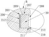
所述移动终端100包括柔性显示屏10、指纹识别模组30及壳体20。所述壳体20具有相连接的顶面201和侧面202,所述顶面201朝向用户设置,用于承载所述柔性显示屏10。所述侧面202设有安装槽203,所述安装槽203的开口208朝向所述壳体20外,所述安装槽203用于收容所述指纹识别模组30。所述柔性显示屏10包括相连接的固定部101和活动部102,所述固定部101贴合于所述顶面201,所述活动部102伸出所述顶面201。所述活动部102相对于所述固定部101弯折时,所述活动部102覆盖于所述侧面202上,所述指纹识别模组30透过所述柔性显示屏10进行指纹识别。所述活动部102相对于所述固定部101展平时,所述指纹识别模组30暴露于所述柔性显示屏10外,以便于手指贴合于所述侧面202进行指纹识别。本实施例中,所述活动部102覆盖于所述侧面202上是指活动部102接触于侧面202,但是活动部102与侧面202之间的贴合作用和固定部101与顶面201之间的贴合作用不同,前者是活动贴合,面面之间相接触,后者是固定贴合,面面之间相固定。The
在本实施例中,组装所述移动终端100时,可先将所述指纹识别模组30装入所述壳体20侧面202上的所述安装槽203内,然后将所述柔性显示屏10的固定部101贴合于所述壳体20的顶面201上,使所述壳体20顶面201成为柔性显示屏10的承载面。所述柔性显示屏10的活动部102自由弯折,使所述柔性显示屏10展开以呈现大显示屏,或使所述柔性显示屏10折叠以便于收纳和携带。当所述活动部102相对于所述固定部101弯折时,所述活动部102覆盖所述侧面202,以使所述指纹识别模组30设于所述柔性显示屏10与所述壳体20之间。此时,当用户将手指放置于所述柔性显示屏10上对应于所述指纹识别模组30的区域,所述指纹识别模组30透过所述柔性显示屏10发射光信号,该光信号经过手指指纹反射后,透过所述柔性显示屏10,被所述指纹识别模组30接收,进而实现用户的指纹采集和识别。当所述活动部102相对于所述固定部101展平时,此时所述柔性显示屏10铺展于所述顶面201所在的平面上,使得所述指纹识别模组30暴露于所述柔性显示屏10外,用户可以直接将手指放置于指纹识别模组30上方,以实现指纹识别。In this embodiment, when assembling the
由于指纹识别模组30设于所述壳体20的顶面201之外,在所述移动终端100的组装过程中,所述柔性显示屏10直接贴合于所述壳体20的顶面201,那么所述指纹识别模组30不会妨碍所述柔性显示屏10与所述壳体20之间的固定,进而提高所述柔性显示屏10的安装平整性;此外,柔性显示屏10在折叠状态时,所述指纹识别模组30与所述柔性显示屏10层叠设置,提高了所述移动终端100的屏占比;柔性显示屏10在折叠状态时,用户透过所述柔性显示屏10进行指纹识别,所述柔性显示屏10呈展开状态时,用户将手指直接放在所述壳体20上进行指纹识别,实现了柔性显示屏10在展开和折叠状态下呈现不同的指纹识别方式,增加趣味性,提高了用户体验。Since the
本实施例中,所述指纹识别模组30为光学式指纹识别模组30,通过光信号识别指纹图像。所述指纹识别模组30所识别的光信号可由其自身发出,穿过所述柔性显示屏10后被用户手指反射,或者由柔性显示屏10发出后被用户手指反射,反射光线穿过所述柔性显示屏10后进入所述指纹识别模组30。当然,在其他的实施方式中,所述指纹识别模组30还可以是电容式指纹识别模组30及超声波指纹识别模组30等。In this embodiment, the
可选的,所述柔性显示屏10为可弯折的显示面板。所述柔性显示屏10可为触控屏,以同时实现显示和触控功能。所述柔性显示屏10可为OLED(Organic Light-EmittingDiode,有机激光显示)显示面板。Optionally, the
本实施例中,请参阅图2,所述侧面202包括底面204和周面205,所述底面204与所述顶面201相对设置,所述周面205连接于所述顶面201与所述底面204之间。可选的,安装槽203可以设于所述侧面202或设于底面204。所述安装槽203的数量可以为多个。所述多个安装槽203可以设于所述侧面202或/和设于底面204。多个指纹识别模组30设于所述多个安装槽203中。In this embodiment, please refer to FIG. 2 , the
请参阅图3,在一种具体的实施方式中,所述安装槽203设于所述壳体20的周面205。所述柔性显示屏10呈展开状态时,所述柔性显示屏10在所述顶面201所在平面内铺展,由于所述周面205与顶面201相交,那么所述柔性显示屏10不会遮盖于所述周面205,所以所述指纹识别模组30暴露于柔性显示屏10外。Please refer to FIG. 3 , in a specific implementation manner, the
所述柔性显示屏10呈折叠状态时,所述活动部102相对于所述固定部101朝向所述周面205弯曲,并覆盖于所述周面205,此时,所述固定部101可以贴合于所述周面205,从而使所述指纹识别模组30设于所述壳体20与所述柔性显示屏10之间,所述指纹识别模组30通过所述柔性显示屏10进行指纹采集。When the
可以理解的,本实施中的所述柔性显示屏10具有透光区103,所述活动部102覆盖所述侧面202时,所述透光区103正对于所述安装槽203,以便于所述指纹识别模组30通过所述透光区103发送和采集光信号。It can be understood that the
作为一种可选的实施例,请参阅图4,所述安装槽203具有朝向壳体20外的开口208,还包括底壁206及侧壁207,所述底壁206与所述开口208相对,所述侧壁207连接于所述底壁206与所述开口208,所述指纹识别模组30贴合于所述底壁206设置。所述指纹识别模组30可粘接所述槽底壁206。可以理解的,本申请对于所述安装槽203的形状和尺寸不做限定。As an optional embodiment, please refer to FIG. 4 , the
可选的,所述侧壁207设有抵持部209,所述抵持部209抵持于所述指纹识别模组30的周侧,以提高所述指纹识别模组30在所述安装槽203中的安装稳定性,进而增加所述指纹识别模组30的识别效率。Optionally, the
在一种具体的实施方式中,所述柔性显示屏10覆盖于所述侧面202时,所述柔性显示屏10大致平行于所述侧面202。所述指纹识别模组30的信号采集面与所述指纹识别模组30的贴合于所述底壁206的表面之间形成一定的相对位置关系,例如平行或形成预定夹角等。优选地,所述指纹识别模组30的信号采集面与所述指纹识别模组30的贴合于所述槽底壁206的表面相平行。那么,设置所述底壁206与所述侧面202相平行,可使得所述指纹识别模组30的信号采集面平行于所述柔性显示屏10,这样所述指纹识别模组30能够更好地采集透过所述柔性显示屏10的光信号,因此,所述指纹识别模组30具有更高的识别准确度。In a specific implementation manner, when the
可选的,所述安装槽203的深度可以大于所述指纹识别模组30的厚度。此时,所述指纹识别模组30不仅能够完全收容于所述安装槽203,并且所述指纹识别模组30与所述侧面202之间形成间隙,降低了装配难度,并预留空间给予其他装配零件。Optionally, the depth of the
作为一种可选的实施例,在上述实施例的基础上,请参阅图4,所述壳体20还包括限位块210,所述限位块210凸设于所述安装槽203的侧壁207上,所述限位块210具有第一限位面211,所述第一限位面211朝向所述底壁206,所述指纹识别模组30远离所述底壁206的表面抵持至所述第一限位面211。As an optional embodiment, on the basis of the above embodiment, please refer to FIG. 4 , the
在本实施例中,所述第一限位面211用于对所述指纹识别模组30在朝向所述安装槽203开口208方向上的位置进行限制,通过对所述第一限位面211的设置,提高所述指纹识别模组30在所述安装槽203轴向的安装稳定性,进而增加所述指纹识别模组30的识别效率。In this embodiment, the first limiting
在本实施例中,所述限位块210在外力作用下具有一定的形变能力,通过外力使所述限位块210发生变形,将所述指纹识别模组30装入所述安装槽203后,撤去所述外力,则所述限位块210恢复原状。所述限位块210的设置有利于降低所述指纹识别模组30的组装难度。In this embodiment, the limiting
可选的,所述安装槽203的底壁206上设有压紧件212。所述压紧件212在外力作用下发生形变。所述压紧件212用于将所述指纹识别模组30压紧在所述第一限位面211上。此时,所述底壁206、所述压紧件212以及所述第一限位面211之间相互配合,能够更好地对所述指纹识别模组30进行限位。同时,所述压紧件212可吸收一部分的工艺公差,从而降低所述指纹识别模组30的组装难度。Optionally, a pressing
具体而言,所述压紧件212为弹性件,例如弹簧、泡棉、橡胶等。当然,在其他实施方式中,所述压紧件212也可为柔性件,所述压紧件212能够配合压紧所述指纹识别模组30即可。Specifically, the pressing
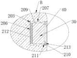
作为一种可选的实施例,在上述实施例的基础上,请参阅图5,所述移动终端100还包括透光盖板40,所述透光盖板40遮盖于所述安装槽203的开口208。所述透光盖板40设于所述安装槽203的开口208处,具体可以设于所述安装槽203开口208内或所述安装槽203开口208外。所述透光盖板40,在透过指纹识别的光信号的同时,还起到了遮挡灰尘、水渍、保护安装槽203内的指纹识别模组30免于损伤等的作用。本实施例可以单独实施或结合以上的实施例进行实施。As an optional embodiment, on the basis of the above embodiments, please refer to FIG. 5 , the
进一步地,所述透光盖板40的颜色与所述侧面202的颜色相同或相近,也就是说,用户用肉眼难以分辨出所述透光盖板40与所述侧面202的颜色差异,不会在视觉上产生色差,从而隐藏所述安装槽203,提高移动终端100整体的视觉效果。Further, the color of the
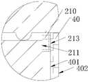
进一步地,请参阅图6,所述限位块210在所述安装槽203的侧壁207上形成第二限位面213,所述第二限位面213朝向所述安装槽203的开口208。所述透光盖板40具有第一表面401,所述第一表面401朝向所述底壁206,所述第一表面401抵持于所述第二限位面213。所述第二限位面213用于对所述透光盖板40朝向所述底壁206方向上的位置进行限制,通过对所述第二限位面213的设置,提高所述透光盖板40在所述安装槽203轴向的安装稳定性。Further, please refer to FIG. 6 , the limiting
可选的,所述透光盖板40可以贴合于所述安装槽203的开口208外,或者位于所诉安装槽203中。当所述透光盖板40安装于所述安装槽203中时,所述透光盖板40的尺寸可以与所述安装槽203开口208的尺寸大致相同,使得所述透光盖板40刚好安装于所述安装槽203中。在此情况下,可以将所述透光盖板40的周侧粘接于所述安装槽203的侧壁207,以将所述透光盖板40固定于所述安装槽203中。Optionally, the light-transmitting
进一步地,所述透光盖板40还具有与所述第一表面401相对设置的第二表面402,所述第二表面402与所述侧面202齐平。所述第一表面401平行于所述第二表面402。指纹识别模组30的信号采集面与所述侧面202平行,那么指纹识别模组30的信号采集面也平行于所述第一表面401和所述第二表面402,这样指纹识别模组30发射和采集的光信号可以直接透射过所述透光盖板40,不会被第一表面401和第二表面402折射掉,从而减少了光信号损耗,提高指纹识别的准确率和识别效率。Further, the light-transmitting
当指纹识别模组30暴露于柔性显示屏10外时,手指可以直接放置于所述第二表面402上,以进行指纹识别,所述第二表面402与所述侧面202齐平的设置,可以增加手指放置于第二表面402时的舒适感。When the
所述活动部102相对于所述固定部101弯折时,所述柔性显示屏10贴合于所述第二表面402和所述侧面202。这样使得所述柔性显示屏10平行于所述第二表面402,减少了光信号损耗。所述第二表面402与所述侧面202齐平的设置,可以增加所述柔性显示屏10的贴合平整度,提高指纹识别准确率。When the
本申请实施例提供的一种移动终端100,壳体20中还包括主板、电源等部件(未图示),所述指纹识别模组30电连接于所述主板,所述主板电连接于所述电源,所述主板、所述电源与所述指纹识别模组30相配合以实现移动终端100的指纹识别功能,这些部件的具体结构、位置关系、连接关系和控制关系可以有多种实现方式,在此不做限定。In the
以上对本发明实施例进行了详细介绍,本文中应用了具体个例对本发明的原理及实施方式进行了阐述,以上实施例的说明只是用于帮助理解本发明的方法及其核心思想;同时,对于本领域的一般技术人员,依据本发明的思想,在具体实施方式及应用范围上均会有改变之处,综上所述,本说明书内容不应理解为对本发明的限制。The embodiments of the present invention have been described in detail above, and specific examples have been used in this paper to illustrate the principles and implementation methods of the present invention. The descriptions of the above embodiments are only used to help understand the method and core idea of the present invention; at the same time, for Those skilled in the art will have changes in the specific implementation and scope of application according to the idea of the present invention. In summary, the contents of this specification should not be construed as limiting the present invention.
Claims (10)
Priority Applications (1)
| Application Number | Priority Date | Filing Date | Title |
|---|---|---|---|
| CN201910593318.8ACN110362156B (en) | 2017-05-22 | 2017-05-22 | Mobile terminal |
Applications Claiming Priority (2)
| Application Number | Priority Date | Filing Date | Title |
|---|---|---|---|
| CN201710366590.3ACN107257396B (en) | 2017-05-22 | 2017-05-22 | mobile terminal |
| CN201910593318.8ACN110362156B (en) | 2017-05-22 | 2017-05-22 | Mobile terminal |
Related Parent Applications (1)
| Application Number | Title | Priority Date | Filing Date |
|---|---|---|---|
| CN201710366590.3ADivisionCN107257396B (en) | 2017-05-22 | 2017-05-22 | mobile terminal |
Publications (2)
| Publication Number | Publication Date |
|---|---|
| CN110362156A CN110362156A (en) | 2019-10-22 |
| CN110362156Btrue CN110362156B (en) | 2023-02-14 |
Family
ID=60027627
Family Applications (2)
| Application Number | Title | Priority Date | Filing Date |
|---|---|---|---|
| CN201910593318.8AExpired - Fee RelatedCN110362156B (en) | 2017-05-22 | 2017-05-22 | Mobile terminal |
| CN201710366590.3AExpired - Fee RelatedCN107257396B (en) | 2017-05-22 | 2017-05-22 | mobile terminal |
Family Applications After (1)
| Application Number | Title | Priority Date | Filing Date |
|---|---|---|---|
| CN201710366590.3AExpired - Fee RelatedCN107257396B (en) | 2017-05-22 | 2017-05-22 | mobile terminal |
Country Status (8)
| Country | Link |
|---|---|
| US (1) | US10430630B2 (en) |
| EP (1) | EP3407579B1 (en) |
| JP (1) | JP6768962B2 (en) |
| CN (2) | CN110362156B (en) |
| AU (1) | AU2018274298B2 (en) |
| ES (1) | ES2745063T3 (en) |
| TW (1) | TWI659365B (en) |
| WO (1) | WO2018214621A1 (en) |
Families Citing this family (19)
| Publication number | Priority date | Publication date | Assignee | Title |
|---|---|---|---|---|
| CN106993072A (en) | 2017-05-12 | 2017-07-28 | 广东欧珀移动通信有限公司 | Shell and mobile terminal |
| CN110362156B (en)* | 2017-05-22 | 2023-02-14 | Oppo广东移动通信有限公司 | Mobile terminal |
| US11275920B1 (en)* | 2017-09-27 | 2022-03-15 | Apple Inc. | Elongated fingerprint sensor |
| CN110502068A (en)* | 2018-05-18 | 2019-11-26 | 上海和辉光电有限公司 | A kind of display device |
| WO2020215187A1 (en)* | 2019-04-22 | 2020-10-29 | 深圳市汇顶科技股份有限公司 | Device for fingerprint recognition and electronic device |
| CN110320973B (en)* | 2019-06-20 | 2021-07-16 | 维沃移动通信有限公司 | Terminal Equipment |
| CN110321831A (en)* | 2019-06-28 | 2019-10-11 | 维沃移动通信有限公司 | Fingerprint module and mobile terminal |
| TWI724807B (en)* | 2019-07-24 | 2021-04-11 | 友達光電股份有限公司 | Flexible apparatus |
| CN112395899A (en)* | 2019-08-01 | 2021-02-23 | Oppo(重庆)智能科技有限公司 | Electronic device, control method and device thereof, and computer-readable storage medium |
| CN112860008A (en)* | 2019-11-28 | 2021-05-28 | 北京小米移动软件有限公司 | Display screen module, terminal equipment and fingerprint identification method |
| CN111459226A (en)* | 2020-03-31 | 2020-07-28 | 联想(北京)有限公司 | Electronic device and method for mounting electronic device |
| US11189248B1 (en) | 2020-05-06 | 2021-11-30 | Apple Inc. | Systems and methods for switching vision correction graphical outputs on a display of an electronic device |
| US12093359B2 (en) | 2020-09-25 | 2024-09-17 | Apple Inc. | Electronic device having a sealed biometric input system |
| CN112272248B (en)* | 2020-10-26 | 2022-05-20 | Oppo广东移动通信有限公司 | electronic device |
| US11783629B2 (en) | 2021-03-02 | 2023-10-10 | Apple Inc. | Handheld electronic device |
| CN113066371B (en)* | 2021-03-19 | 2022-09-27 | 武汉华星光电半导体显示技术有限公司 | Display device and manufacturing method thereof |
| CN113542467B (en)* | 2021-07-13 | 2023-06-30 | 深圳市光千合新材料科技有限公司 | Waterproof fingerprint identification device for mobile phone |
| KR20230050047A (en) | 2021-10-07 | 2023-04-14 | 삼성전자주식회사 | Electronic device including fingerprint sensor |
| CN115661874B (en)* | 2022-10-26 | 2025-09-26 | 维沃移动通信有限公司 | Foldable electronic devices |
Citations (10)
| Publication number | Priority date | Publication date | Assignee | Title |
|---|---|---|---|---|
| CN104158926A (en)* | 2014-07-16 | 2014-11-19 | 惠州Tcl移动通信有限公司 | Intelligent mobile terminal |
| CN104951233A (en)* | 2015-06-18 | 2015-09-30 | 广东欧珀移动通信有限公司 | Mobile terminal |
| CN105068605A (en)* | 2015-07-31 | 2015-11-18 | 信利光电股份有限公司 | Cover plate and electronic device |
| CN105278902A (en)* | 2014-07-25 | 2016-01-27 | Lg电子株式会社 | Mobile terminal and control method thereof |
| WO2016106519A1 (en)* | 2014-12-29 | 2016-07-07 | 深圳市柔宇科技有限公司 | Portable terminal |
| CN105872137A (en)* | 2016-03-25 | 2016-08-17 | 广东欧珀移动通信有限公司 | Display screen component and mobile terminal having same |
| CN106293236A (en)* | 2016-08-12 | 2017-01-04 | 京东方科技集团股份有限公司 | A kind of display floater and display device |
| CN106603773A (en)* | 2017-01-26 | 2017-04-26 | 广东欧珀移动通信有限公司 | Display device and mobile terminal |
| CN106662900A (en)* | 2016-09-29 | 2017-05-10 | 深圳市汇顶科技股份有限公司 | Screen component and electronic equipment with fingerprint module |
| CN107257396A (en)* | 2017-05-22 | 2017-10-17 | 广东欧珀移动通信有限公司 | Mobile terminal |
Family Cites Families (21)
| Publication number | Priority date | Publication date | Assignee | Title |
|---|---|---|---|---|
| JP2004287809A (en)* | 2003-03-20 | 2004-10-14 | Olympus Corp | Information terminal device |
| JP2006287982A (en)* | 2005-07-13 | 2006-10-19 | Columbus No Tamagotachi:Kk | Portable communication terminal with flexible display |
| JP2010122015A (en)* | 2008-11-18 | 2010-06-03 | Fujitsu Ltd | Sensor unit and method for manufacturing electronic apparatus |
| TWI424307B (en)* | 2009-04-29 | 2014-01-21 | E Ink Holdings Inc | Electronic apparatus having movable input device(s) |
| TWI490789B (en)* | 2011-05-03 | 2015-07-01 | Synaptics Inc | Fingerprint sensor and integratable electronic display |
| KR102086715B1 (en)* | 2012-11-01 | 2020-03-09 | 삼성전자주식회사 | Control Method for outputting a display screen based on a flexible display unit and electronic device |
| US9155367B2 (en)* | 2013-03-14 | 2015-10-13 | Incipio Technologies, Inc. | Biometric and proximity sensor compatible protective case for mobile device |
| EP2866165B1 (en)* | 2013-10-28 | 2018-12-05 | LG Electronics Inc. -1- | Mobile terminal and controlling method thereof |
| KR20150063780A (en)* | 2013-12-02 | 2015-06-10 | 엘지전자 주식회사 | Mobile terminal |
| KR102228857B1 (en)* | 2014-09-05 | 2021-03-17 | 엘지전자 주식회사 | Protable electronic device |
| CN105578811B (en)* | 2014-10-17 | 2018-09-04 | 小米科技有限责任公司 | Electronic equipment and electronic equipment application method |
| KR102161694B1 (en)* | 2014-10-20 | 2020-10-05 | 삼성전자주식회사 | Display apparatus and display method thereof |
| US10254863B2 (en)* | 2014-12-19 | 2019-04-09 | Lg Electronics Inc. | Mobile terminal |
| CN105511661B (en)* | 2015-02-03 | 2017-08-29 | 宸鸿科技(厦门)有限公司 | Contactor control device |
| CN104866223A (en)* | 2015-05-13 | 2015-08-26 | 努比亚技术有限公司 | Touch operation method and apparatus |
| CN205384625U (en)* | 2015-06-05 | 2016-07-13 | 旭硝子株式会社 | Glass substrate , protection glass and key fob |
| CN105138074B (en)* | 2015-07-23 | 2017-06-23 | 广东欧珀移动通信有限公司 | Terminal |
| CN105068685B (en)* | 2015-07-30 | 2018-01-19 | 广东欧珀移动通信有限公司 | Terminal |
| US9710689B2 (en)* | 2015-10-30 | 2017-07-18 | Essential Products, Inc. | Fingerprint sensors for mobile devices |
| CN105872138B (en)* | 2016-03-29 | 2019-04-26 | 联想(北京)有限公司 | A kind of electronic equipment |
| CN107291155B (en)* | 2017-05-22 | 2019-05-17 | Oppo广东移动通信有限公司 | Mobile terminal |
- 2017
- 2017-05-22CNCN201910593318.8Apatent/CN110362156B/ennot_activeExpired - Fee Related
- 2017-05-22CNCN201710366590.3Apatent/CN107257396B/ennot_activeExpired - Fee Related
- 2018
- 2018-01-26TWTW107102877Apatent/TWI659365B/ennot_activeIP Right Cessation
- 2018-03-09EPEP18161010.6Apatent/EP3407579B1/enactiveActive
- 2018-03-09ESES18161010Tpatent/ES2745063T3/enactiveActive
- 2018-03-15JPJP2019534729Apatent/JP6768962B2/ennot_activeExpired - Fee Related
- 2018-03-15WOPCT/CN2018/079192patent/WO2018214621A1/ennot_activeCeased
- 2018-03-15AUAU2018274298Apatent/AU2018274298B2/ennot_activeCeased
- 2018-03-22USUS15/928,694patent/US10430630B2/enactiveActive
Patent Citations (10)
| Publication number | Priority date | Publication date | Assignee | Title |
|---|---|---|---|---|
| CN104158926A (en)* | 2014-07-16 | 2014-11-19 | 惠州Tcl移动通信有限公司 | Intelligent mobile terminal |
| CN105278902A (en)* | 2014-07-25 | 2016-01-27 | Lg电子株式会社 | Mobile terminal and control method thereof |
| WO2016106519A1 (en)* | 2014-12-29 | 2016-07-07 | 深圳市柔宇科技有限公司 | Portable terminal |
| CN104951233A (en)* | 2015-06-18 | 2015-09-30 | 广东欧珀移动通信有限公司 | Mobile terminal |
| CN105068605A (en)* | 2015-07-31 | 2015-11-18 | 信利光电股份有限公司 | Cover plate and electronic device |
| CN105872137A (en)* | 2016-03-25 | 2016-08-17 | 广东欧珀移动通信有限公司 | Display screen component and mobile terminal having same |
| CN106293236A (en)* | 2016-08-12 | 2017-01-04 | 京东方科技集团股份有限公司 | A kind of display floater and display device |
| CN106662900A (en)* | 2016-09-29 | 2017-05-10 | 深圳市汇顶科技股份有限公司 | Screen component and electronic equipment with fingerprint module |
| CN106603773A (en)* | 2017-01-26 | 2017-04-26 | 广东欧珀移动通信有限公司 | Display device and mobile terminal |
| CN107257396A (en)* | 2017-05-22 | 2017-10-17 | 广东欧珀移动通信有限公司 | Mobile terminal |
Also Published As
| Publication number | Publication date |
|---|---|
| CN107257396B (en) | 2019-07-26 |
| CN110362156A (en) | 2019-10-22 |
| AU2018274298A1 (en) | 2019-07-11 |
| CN107257396A (en) | 2017-10-17 |
| EP3407579B1 (en) | 2019-08-28 |
| JP6768962B2 (en) | 2020-10-14 |
| US10430630B2 (en) | 2019-10-01 |
| AU2018274298B2 (en) | 2020-09-17 |
| TW201901522A (en) | 2019-01-01 |
| EP3407579A1 (en) | 2018-11-28 |
| US20180336391A1 (en) | 2018-11-22 |
| ES2745063T3 (en) | 2020-02-27 |
| TWI659365B (en) | 2019-05-11 |
| WO2018214621A1 (en) | 2018-11-29 |
| JP2020504381A (en) | 2020-02-06 |
Similar Documents
| Publication | Publication Date | Title |
|---|---|---|
| CN110362156B (en) | Mobile terminal | |
| KR102661598B1 (en) | Foldable electronic device including protection member | |
| CN107241468B (en) | Display device and mobile terminal | |
| CN109885131B (en) | mobile terminal | |
| CN111433708B (en) | Electronic device with light absorbing member between display panel and ultrasonic sensor | |
| CN108885694B (en) | Fingerprint Identification Components and Terminals | |
| EP3321847A1 (en) | Screen assembly having fingerprint module, and electronic device | |
| CN105072221B (en) | Display screen assembling structure and its mobile terminal device | |
| CN211928482U (en) | Electronic device | |
| CN107180599A (en) | Display screen, display device and mobile terminal | |
| WO2019052332A1 (en) | Display screen assembly and mobile terminal | |
| CN104599593A (en) | Display device | |
| CN106993072A (en) | Shell and mobile terminal | |
| CN114303114A (en) | Electronic device comprising a flexible display | |
| CN112887542B (en) | Electronic device | |
| CN117063460A (en) | Electronic device comprising a sweeper | |
| CN204925914U (en) | Electronic equipment with fingerprint identification function | |
| CN113037894A (en) | Electronic equipment | |
| CN217217080U (en) | Electronic components and electronic equipment | |
| CN110502071A (en) | Screen components and terminal equipment | |
| EP3992843A1 (en) | Optical module and mobile terminal | |
| HK1242085B (en) | Mobile terminal | |
| HK1242085A1 (en) | Mobile terminal | |
| HK1242085A (en) | Mobile terminal | |
| CN204946032U (en) | A kind of fingerprint sensor module and electronic equipment |
Legal Events
| Date | Code | Title | Description |
|---|---|---|---|
| PB01 | Publication | ||
| PB01 | Publication | ||
| SE01 | Entry into force of request for substantive examination | ||
| SE01 | Entry into force of request for substantive examination | ||
| GR01 | Patent grant | ||
| GR01 | Patent grant | ||
| CF01 | Termination of patent right due to non-payment of annual fee | ||
| CF01 | Termination of patent right due to non-payment of annual fee | Granted publication date:20230214 |